


1. Introduction
Supernova remnants (SNRs) play an essential role in the structure of galaxies, enriching the Interstellar Medium (ISM) as well as having a significant impact on the structure and physical properties of the ISM. The study of SNRs in our own Galaxy is not ideal because of difficulties of making accurate distance measurements. Instead, we study SNRs in nearby, small, dwarf galaxies, including the Large Magellanic Cloud (LMC) located at a distance of 50 kpc (Macri et al., Reference Macri, Stanek, Bersier, Greenhill and Reid2006; Pietrzyński et al., Reference Pietrzyński, Graczyk and Gallenne2019). Because all objects within this galaxy are located at approximately the same distance, physical measurements, including the physical size, are more reliable. The almost face-on orientation of the LMC (inclination angle of $\sim$
35
$\sim$
35 $^{\circ}$
, van der Marel & Cioni, Reference van der Marel and Cioni2001) allows deep, high-resolution (spatial and spectral) multi-frequency observations (Maggi et al., Reference Maggi, Haberl and Kavanagh2016; Bozzetto et al., Reference Bozzetto, Filipović and Vukotić2017). Moreover, the LMC contains active star-forming regions, and is located away from the Galactic plane where absorption by gas and dust is reasonably low.
$^{\circ}$
, van der Marel & Cioni, Reference van der Marel and Cioni2001) allows deep, high-resolution (spatial and spectral) multi-frequency observations (Maggi et al., Reference Maggi, Haberl and Kavanagh2016; Bozzetto et al., Reference Bozzetto, Filipović and Vukotić2017). Moreover, the LMC contains active star-forming regions, and is located away from the Galactic plane where absorption by gas and dust is reasonably low.
To date, numerous studies have investigated SNRs within the LMC. Maggi et al. (Reference Maggi, Haberl and Kavanagh2016) reported 59 SNRs as X-ray emitters, and the radio-continuum studies of Bozzetto et al. (Reference Bozzetto, Filipović and Vukotić2017) have added 15 candidates to that list. Leahy (Reference Leahy2017) studied the most energetic and brightest LMC SNRs using an analysis of the Maggi et al. (Reference Maggi, Haberl and Kavanagh2016) SNR sample. Maitra et al. (Reference Maitra, Haberl and Filipović2019, Reference Maitra, Haberl and Maggi2021) promoted two additional objects as bona fide SNRs; Yew et al. (Reference Yew, Filipović and Stupar2021) discovered two new optical SNRs and 14 candidates. Most recently, Kavanagh et al. (Reference Kavanagh, Sasaki and Filipović2022); Bozzetto et al. (Reference Bozzetto, Filipović and Sano2023); Filipović et al. (Reference Filipović, Payne and Alsaberi2022); Zangrandi et al. (Reference Zangrandi, Jurk and Sasaki2024) confirmed eight new LMC SNRs and suggested an additional 15 as ‘good’ candidates. This currently gives us a total of 71 confirmed LMC SNRs and an additional 20 candidates. Thirteen SNRs are confirmed and two candidates are possible Type Ia remnants (Bozzetto et al., Reference Bozzetto, Filipović and Vukotić2017).
MC SNR J0519–6902 (also known as LHG 26) was initially discovered using the Einstein observatory (Long et al., Reference Long, Helfand and Grabelsky1981). Tuohy et al. (Reference Tuohy, Dopita, Mathewson, Long and Helfand1982) confirmed the SNR is Balmer-dominated with a broad H $\alpha$
component. They reported an X-ray angular size of
$\alpha$
component. They reported an X-ray angular size of $\sim$
30” and an optical angular size of 28” with a forward shock velocity of
$\sim$
30” and an optical angular size of 28” with a forward shock velocity of $2\,900\pm400$
km s
$2\,900\pm400$
km s $^{-1}$
. They suggest the remnant is expanding into a low-density region composed of neutral hydrogen, inferring a Type Ia Type Ia Supernova (SN) with an estimated progenitor mass of between 1.2 and 4.0 M
$^{-1}$
. They suggest the remnant is expanding into a low-density region composed of neutral hydrogen, inferring a Type Ia Type Ia Supernova (SN) with an estimated progenitor mass of between 1.2 and 4.0 M $_{\odot}$
. Kosenko et al. (Reference Kosenko, Helder and Vink2010) used Chandra and XMM-Newton observations to estimate the velocity for the forward shock of
$_{\odot}$
. Kosenko et al. (Reference Kosenko, Helder and Vink2010) used Chandra and XMM-Newton observations to estimate the velocity for the forward shock of $2\,770\pm500$
km s
$2\,770\pm500$
km s $^{-1}$
with no strong non-thermal X-ray continuum emission. Hovey et al. (Reference Hovey, Hughes, McCully, Pandya and Eriksen2018) used optical data to report a forward shock velocity of 2 650 km s
$^{-1}$
with no strong non-thermal X-ray continuum emission. Hovey et al. (Reference Hovey, Hughes, McCully, Pandya and Eriksen2018) used optical data to report a forward shock velocity of 2 650 km s $^{-1}$
.
$^{-1}$
.
Chu & Kennicutt (Reference Chu and Kennicutt1988) associated MC SNR J0519–6902 with the nearby (200 pc) population II OB association – LH41. Desai et al. (Reference Desai, Chu and Gruendl2010) found no young stellar object associated with this SNR, while Edwards et al. (Reference Edwards, Pagnotta and Schaefer2012) reported that this SNR could have only been a Type Ia SN event resulting from a supersoft X-ray source or a double degenerate system.
Mathewson et al. (Reference Mathewson, Ford and Dopita1983) estimated a radio spectral index Footnote a for MC SNR J0519–6902 of $\alpha$
=–0.6, while Mills et al. (Reference Mills, Turtle, Little and Durdin1984) reported an index of –0.65. Bozzetto et al. (Reference Bozzetto, Filipović, Urosevic and Crawford2012) listed a spectral index of
$\alpha$
=–0.6, while Mills et al. (Reference Mills, Turtle, Little and Durdin1984) reported an index of –0.65. Bozzetto et al. (Reference Bozzetto, Filipović, Urosevic and Crawford2012) listed a spectral index of $-0.53\pm0.07$
, which still suggested predominantly synchrotron emission (e.g. Filipović & Tothill, Reference Filipović and Tothill2021) from a typical young SNR (Reynolds et al., Reference Reynolds, Gaensler and Bocchino2012; Galvin & Filipovic, Reference Galvin and Filipovic2014; Bozzetto et al., Reference Bozzetto, Filipović and Vukotić2017; Maggi et al., Reference Maggi, Filipović and Vukotić2019).
$-0.53\pm0.07$
, which still suggested predominantly synchrotron emission (e.g. Filipović & Tothill, Reference Filipović and Tothill2021) from a typical young SNR (Reynolds et al., Reference Reynolds, Gaensler and Bocchino2012; Galvin & Filipovic, Reference Galvin and Filipovic2014; Bozzetto et al., Reference Bozzetto, Filipović and Vukotić2017; Maggi et al., Reference Maggi, Filipović and Vukotić2019).
Tuohy et al. (Reference Tuohy, Dopita, Mathewson, Long and Helfand1982) inferred an age for MC SNR J0519–6902 of $\sim$
500 yrs while Smith et al. (Reference Smith, Kirshner, Blair and Winkler1991) reported an age between 500 and 1 500 yrs. Rest et al. (Reference Rest, Suntzeff and Olsen2005) used a light echo method to estimate an age of
$\sim$
500 yrs while Smith et al. (Reference Smith, Kirshner, Blair and Winkler1991) reported an age between 500 and 1 500 yrs. Rest et al. (Reference Rest, Suntzeff and Olsen2005) used a light echo method to estimate an age of $600\pm200$
yrs. Based on Chandra and XMM-Newton observations, Kosenko et al. (Reference Kosenko, Helder and Vink2010) suggested an age of
$600\pm200$
yrs. Based on Chandra and XMM-Newton observations, Kosenko et al. (Reference Kosenko, Helder and Vink2010) suggested an age of $450\pm200$
yrs. Leahy (Reference Leahy2017) used X-ray emission and temperature to derive an age of
$450\pm200$
yrs. Leahy (Reference Leahy2017) used X-ray emission and temperature to derive an age of $\sim$
2 700 yrs, assuming a shock radius of 4.1 pc expanding in a uniform ISM.
$\sim$
2 700 yrs, assuming a shock radius of 4.1 pc expanding in a uniform ISM.
Dickel & Milne (Reference Dickel and Milne1995) observed this remnant with the Australia Telescope Compact Array (ATCA) at 1 472 and 2 368 MHz. They estimated an average fractional polarisation across the remnant of $1.5\pm0.6$
% and
$1.5\pm0.6$
% and $4.1\pm0.6$
%, respectively. Bozzetto et al. (Reference Bozzetto, Filipović, Urosevic and Crawford2012), who estimated the diameter of this SNR at
$4.1\pm0.6$
%, respectively. Bozzetto et al. (Reference Bozzetto, Filipović, Urosevic and Crawford2012), who estimated the diameter of this SNR at $\sim$
8 pc, found average fractional polarisation values of
$\sim$
8 pc, found average fractional polarisation values of $\sim$
2.2% and
$\sim$
2.2% and $\sim$
3.2% at 5 500 and 9 000 MHz, respectively. They also calculated a calculated a rotation measure (RM) for the entire remnant of
$\sim$
3.2% at 5 500 and 9 000 MHz, respectively. They also calculated a calculated a rotation measure (RM) for the entire remnant of $\sim$
10 rad m
$\sim$
10 rad m $^{-2}$
.
$^{-2}$
.
Vukotic et al. (Reference Vukotic, Arbutina and Urosevic2007) estimated the magnetic field of this SNR, using both a classic and revised equipartition formula to obtain results of 186 and 270 $\mu$
G, respectively. Bozzetto et al. (Reference Bozzetto, Filipović, Urosevic and Crawford2012) used the modified equipartition model from Arbutina et al. (Reference Arbutina, Urošević, Andjelić, Pavlović and Vukotić2012) to estimate the magnetic field to be
$\mu$
G, respectively. Bozzetto et al. (Reference Bozzetto, Filipović, Urosevic and Crawford2012) used the modified equipartition model from Arbutina et al. (Reference Arbutina, Urošević, Andjelić, Pavlović and Vukotić2012) to estimate the magnetic field to be $\sim$
171
$\sim$
171 $\mu$
G with a minimum energy of E
$\mu$
G with a minimum energy of E $_\textrm{min}$
= 1.8
$_\textrm{min}$
= 1.8 $\times10^{49}$
erg.
$\times10^{49}$
erg.
Kosenko et al. (Reference Kosenko, Hillebrandt and Kromer2015) reported a method based on state-of-the-art 3D simulations of thermonuclear SN explosions, coupled with hydrodynamic calculations of SNR evolution, while making use of the most up-to-date atomic data to suggest MC SNR J0519–6902 originated from an oxygen-rich merger. Seitenzahl et al. (Reference Seitenzahl, Ghavamian, Laming and Vogt2019) discovered optical ([Fe XIV] 5303 Å) emission associated with this SNR. Li et al. (Reference Li, Kerzendorf and Chu2019) searched for a surviving companion of MC SNR J0519–6902 and found a candidate run-away companion star moving at a radial velocity of 182 km s $^{-1}$
.
$^{-1}$
.
In this paper, we present new high-resolution ATCA radio continuum images of MC SNR J0519–6902 at 5 500 and 9 000 MHz. In Section 2 we describe our observations and data analyses. Our new findings and discussion are listed in Section 3. Finally, our conclusions are outlined in Section 4.
2. Observation and data analysis
2.1 Radio continuum observations
We observed MC SNR J0519–6902 with ATCA (project codes: CX454 and CX310). ATCA archivalFootnote b data (project code: C634) were also used to produce the high-resolution and sensitive images (see Table 1). All observations were carried out in “snap-shot” mode, with 1-hour of integration over a 12-hour minimum using the Compact Array Broadband Backend (CABB) (2048 MHz bandwidth) at wavelengths of 3/6 cm ( $\nu$
= 4 500–6 500 and 8 000–10 000 MHz centred at 5 500 and 9 000 MHz) totalling
$\nu$
= 4 500–6 500 and 8 000–10 000 MHz centred at 5 500 and 9 000 MHz) totalling $\sim$
580 minutes integration. The primary (flux density) calibrator, PKS B1934–638, with a flux density of 4.96 Jy for 5 500 MHz and 2.70 Jy for 9 000 MHz, and the secondary (phase) calibrator, PKS B0530–727, with a flux density of 0.77 Jy for 5 500 MHz and 0.82 Jy for 9 000 MHz were used for all three observing days.
$\sim$
580 minutes integration. The primary (flux density) calibrator, PKS B1934–638, with a flux density of 4.96 Jy for 5 500 MHz and 2.70 Jy for 9 000 MHz, and the secondary (phase) calibrator, PKS B0530–727, with a flux density of 0.77 Jy for 5 500 MHz and 0.82 Jy for 9 000 MHz were used for all three observing days.
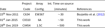
ATCA observations of MC SNR J0519–6902.
miriad
Footnote c (Sault et al., Reference Sault, Teuben, Wright, Shaw, Payne and Hayes1995) and karma
Footnote d (Gooch, Reference Gooch, Shaw, Payne and Hayes1995) software packages were used for data reduction and analysis. Imaging was completed using the multi-frequency synthesis invert task with natural Briggs weighting (robust = 0 for both 5 500 and 9 000 MHz). Beam sizes included $2.3''\times1.7''$
and
$2.3''\times1.7''$
and $1.4''\times1.0''$
for 5 500 and 9 000 MHz images, respectively. mfclean and restor algorithms allowed the images to be deconvolved, with primary beam correction applied using linmos. We followed the same process for stokes Q and U images using a smoothed resolution of
$1.4''\times1.0''$
for 5 500 and 9 000 MHz images, respectively. mfclean and restor algorithms allowed the images to be deconvolved, with primary beam correction applied using linmos. We followed the same process for stokes Q and U images using a smoothed resolution of $5''\times5''$
(see Section 3.2).
$5''\times5''$
(see Section 3.2).
2.2 H i observations
Archival H i data (Kim et al., Reference Kim, Staveley-Smith and Dopita2003) were obtained using the ATCA and Parkes 64-m telescope. The angular resolution of the data is 60′′, corresponding to a spatial resolution of $\sim$
15 pc at the distance of the LMC. The typical noise level is
$\sim$
15 pc at the distance of the LMC. The typical noise level is $\sim$
2.4 K at a velocity resolution of 1.689 km s
$\sim$
2.4 K at a velocity resolution of 1.689 km s $^{-1}$
.
$^{-1}$
.
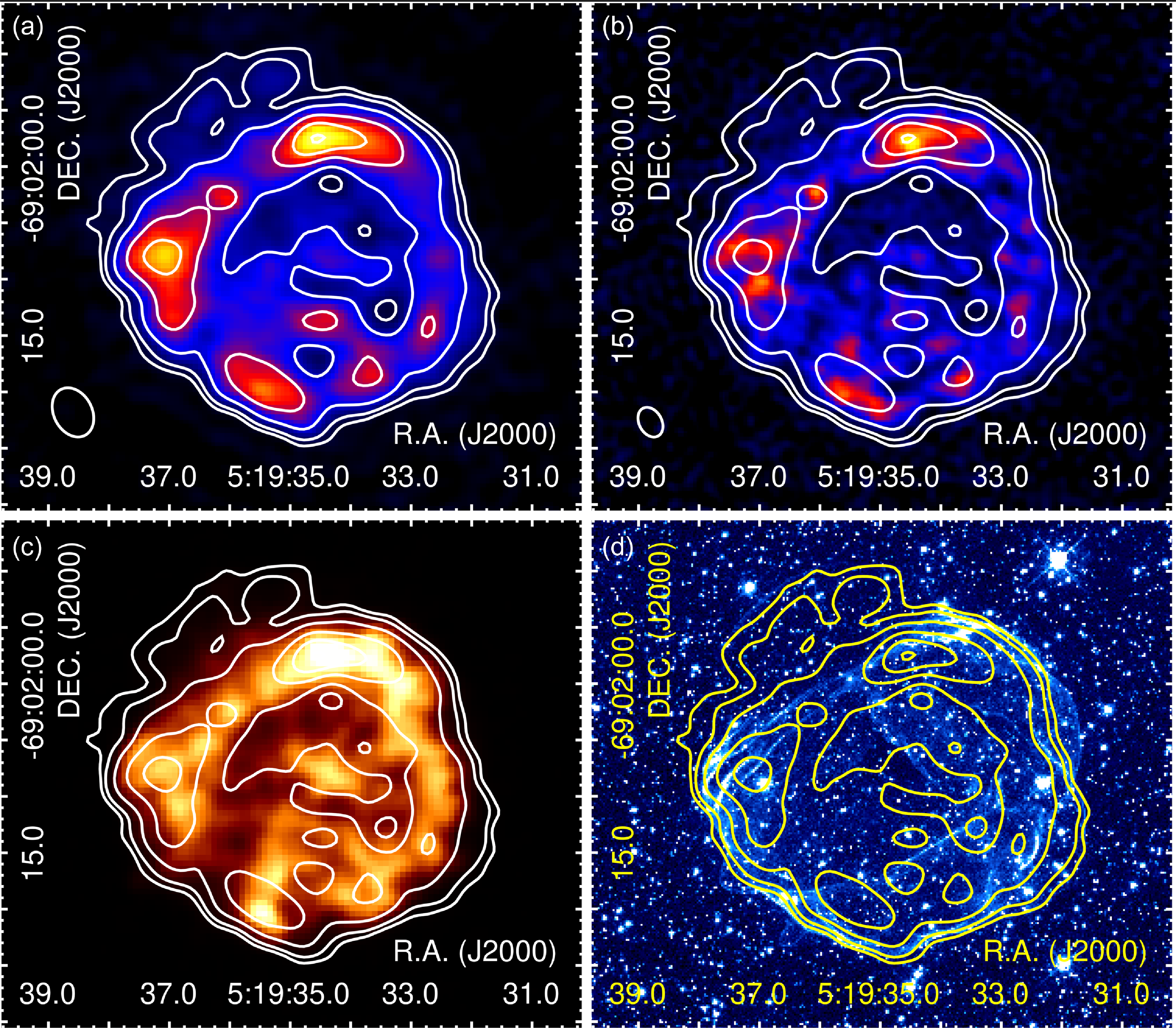
(a) ATCA image at 5 500 MHz of MC SNR J0519–6902. The ellipse in the lower left corner represents a synthesised beam of $2.3''\times1.7''$
with a p.a. of 62
$2.3''\times1.7''$
with a p.a. of 62 $^\circ$
. (b) ATCA image at 9 000 MHz. The ellipse in the lower left corner represents a synthesised beam of
$^\circ$
. (b) ATCA image at 9 000 MHz. The ellipse in the lower left corner represents a synthesised beam of $1.4''\times1.0''$
with a p.a. of 61
$1.4''\times1.0''$
with a p.a. of 61 $^\circ$
. The rms noise of the 5 500 and 9 000 MHz images is 20
$^\circ$
. The rms noise of the 5 500 and 9 000 MHz images is 20 $\mu$
Jy beam
$\mu$
Jy beam $^{-1}$
and 17
$^{-1}$
and 17 $\mu$
Jy beam
$\mu$
Jy beam $^{-1}$
, respectively. (c) Chandra broadband image. (d) HST image (combination of the V-band and H
$^{-1}$
, respectively. (c) Chandra broadband image. (d) HST image (combination of the V-band and H ${\alpha}$
images, Edwards et al., Reference Edwards, Pagnotta and Schaefer2012). 5 500 MHz contour lines overlaid on each image are 0.05, 0.09, 0.2, 0.4, 0.6, and 0.8 mJy beam
${\alpha}$
images, Edwards et al., Reference Edwards, Pagnotta and Schaefer2012). 5 500 MHz contour lines overlaid on each image are 0.05, 0.09, 0.2, 0.4, 0.6, and 0.8 mJy beam $^{-1}$
.
$^{-1}$
.
2.3 Chandra observations
We used archival X-ray data obtained using Chandra for which the observation IDs (Obs IDs) are 118 (PI: S. Holt), 11 241, 12 062, and 12 063 (PI: J. P. Hughes); the data have been published by several authors (e.g., Kosenko et al., Reference Kosenko, Helder and Vink2010; Edwards et al., Reference Edwards, Pagnotta and Schaefer2012; Schenck et al., Reference Schenck, Park and Post2016). All datasets were taken using the Advanced CCD Imaging Spectrometer S-array (ACIS-S3) in June 2000 (Obs ID 118), December 2009 (Obs IDs 11241 and 12062), and in February 2010 (Obs ID 12063). We utilised Chandra Interactive Analysis of Observations (CIAO, Fruscione et al., Reference Fruscione, McDowell, Allen, Silva and Doxsey2006) version 4.12 with CALDB 4.9.1 for data reprocessing and imaging. “Chandra_repro” and “merge_obs” scripts created an exposure-corrected, energy-filtered image at 0.5–7.0 keV (hereafter referred to as “broadband”) with a total effective exposure of $\sim$
91 ks. Lastly, we smoothed the image with a Gaussian kernel of 1′′, Full Width at Half-Maximum (FWHM).
$\sim$
91 ks. Lastly, we smoothed the image with a Gaussian kernel of 1′′, Full Width at Half-Maximum (FWHM).
2.4 Optical HST observations
The Hubble Space Telescope (HST) image of MC SNR J0519–6902 was downloaded from the Mikulski Archive for Space TelescopesFootnote e portal. All details regarding these HST observations and their data reduction are described in Edwards et al. (Reference Edwards, Pagnotta and Schaefer2012).
3. Results and discussion
3.1 Radio morphology
MC SNR J0519–6902 has a ring-like morphology with three bright regions towards the north, east, and south (Bozzetto et al., Reference Bozzetto, Filipović, Urosevic and Crawford2012). In Figure 1, the new ATCA images at 5 500 and 9 000 MHz are compared with the Chandra and HST images. Root Mean Squared (rms) noise for these high resolution ATCA images at 5 500 and 9 000 MHz are $\sim$
20 and
$\sim$
20 and $\sim$
17
$\sim$
17 $\mu$
Jy beam
$\mu$
Jy beam $^{-1}$
, respectively; one order of magnitude better than that obtained by Bozzetto et al. (Reference Bozzetto, Filipović, Urosevic and Crawford2012).
$^{-1}$
, respectively; one order of magnitude better than that obtained by Bozzetto et al. (Reference Bozzetto, Filipović, Urosevic and Crawford2012).
The figure clearly shows a radio emission coincident with X-ray emission suggesting relativistic electrons are associated with the shock-heated gas. Interestingly, the optical emission is outside both the radio continuum and X-ray emission (Figure 1), indicating the optical emission is located at the forward shock. The radio morphology of this SNR is asymmetric in terms of variation in brightness. As noted by Bozzetto et al. (Reference Bozzetto, Filipović, Urosevic and Crawford2012), it features three bright regions located in the north, east, and south (Figure 1), resembling the structure of LMC SNR N 103B (Alsaberi et al., Reference Alsaberi, Barnes and Filipović2019) and Kepler in the Milky Way (MW) (DeLaney et al., Reference DeLaney, Koralesky, Rudnick and Dickel2002). Moreover, our new images show a faint structure on the north-east side of MC SNR J0519–6902 which was not present in previous images (see Figure 1). Although not statistically significant ( ${\lt3\sigma}$
), this feature suggests that the SNR extends further in the north-east direction compared to the other sides (see text for details).
${\lt3\sigma}$
), this feature suggests that the SNR extends further in the north-east direction compared to the other sides (see text for details).
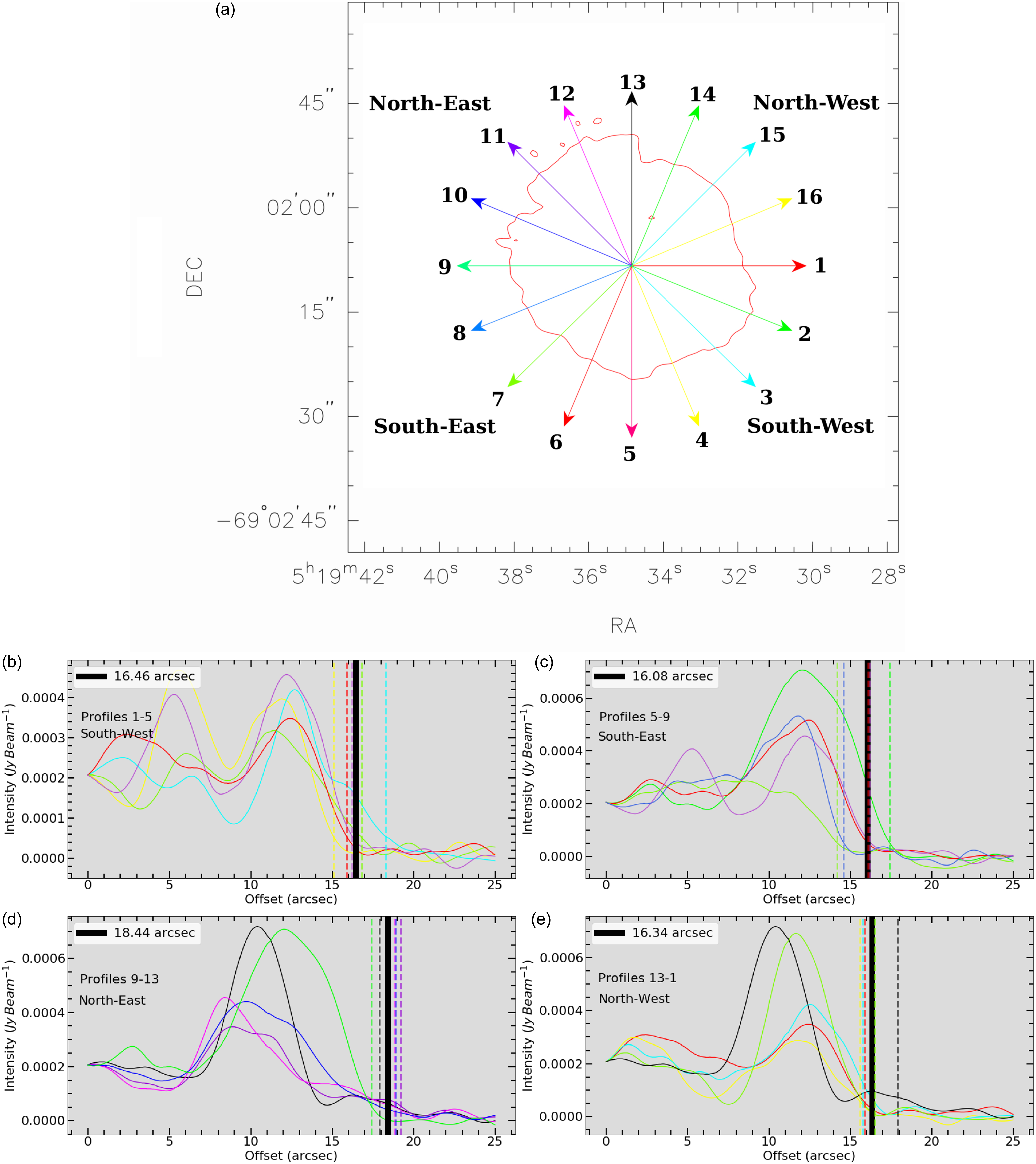
We used the Minkowski tensor analysis tool BANANAFootnote f (Collischon et al., Reference Collischon, Sasaki, Mecke, Points and Klatt2021) to determine the centre of expansion. This tool searches for filaments and calculates normal lines and line density maps. For a perfect shell, all lines should meet at the centre position inside the SNR, where the expansion must have started (see Collischon et al., Reference Collischon, Sasaki, Mecke, Points and Klatt2021, for more details). Since real sources deviate from this ideal picture, we circumvented this problem by smoothing the line density map using a circle with a diameter of 40 pixels. We then took the centre position of the pixel where the line density was the highest. Using the same method, we performed the tensor analysis separately for the 5 500 MHz, 9 000 MHz, and Chandra broad-band images. From this, we calculated the mean centre position and the $1\sigma$
uncertainty of the mean.
$1\sigma$
uncertainty of the mean.
The resulting calculated centre is RA (J2000) = 05 $^{h}$
19
$^{h}$
19 $^{m}$
34.85
$^{m}$
34.85 $^{s}$
, Dec (J2000) =
$^{s}$
, Dec (J2000) = $-$
69
$-$
69 $^\circ$
02’08.22” with an uncertainty of
$^\circ$
02’08.22” with an uncertainty of $\sim$
0.1 arcsec. This is
$\sim$
0.1 arcsec. This is $\sim$
0.32′′ (
$\sim$
0.32′′ ( $\sim$
0.07 pc at the distance of 50 kpc) south-west from the previous estimation by Bozzetto et al. (Reference Bozzetto, Filipović, Urosevic and Crawford2012) (RA(J2000) = 05
$\sim$
0.07 pc at the distance of 50 kpc) south-west from the previous estimation by Bozzetto et al. (Reference Bozzetto, Filipović, Urosevic and Crawford2012) (RA(J2000) = 05 $^{h}$
19
$^{h}$
19 $^{m}$
34.9
$^{m}$
34.9 $^{s}$
, Dec (J2000) = –69
$^{s}$
, Dec (J2000) = –69 $^\circ$
02’07.9”). To calculate the radio continuum radius of this SNR, we used the miriad task cgslice to plot 16 equispaced radial profiles in 22.5
$^\circ$
02’07.9”). To calculate the radio continuum radius of this SNR, we used the miriad task cgslice to plot 16 equispaced radial profiles in 22.5 $^\circ$
segments around the remnant at 5 500 MHz. Each profile is 25” in length (Figure 2). We divide the remnant into four equal regions: south-west (profiles 1–5), south-east (profiles 5–9), north-east (profiles 9–13), and north-west (profiles 13–1) (Figure 2a). We identify the cutoff as the point where each profile intersects the outer contour line (
$^\circ$
segments around the remnant at 5 500 MHz. Each profile is 25” in length (Figure 2). We divide the remnant into four equal regions: south-west (profiles 1–5), south-east (profiles 5–9), north-east (profiles 9–13), and north-west (profiles 13–1) (Figure 2a). We identify the cutoff as the point where each profile intersects the outer contour line ( $3\sigma$
ATCA image contour or 60
$3\sigma$
ATCA image contour or 60 $\mu$
Jy beam
$\mu$
Jy beam $^{-1}$
at 5 500 MHz). These cutoffs are represented as dashed vertical lines (see Figure 2b, c, d, and e). The thick black vertical lines represent the average of the cutoffs in each region. The resulting radii vary from
$^{-1}$
at 5 500 MHz). These cutoffs are represented as dashed vertical lines (see Figure 2b, c, d, and e). The thick black vertical lines represent the average of the cutoffs in each region. The resulting radii vary from $16.46\pm1.19''$
(
$16.46\pm1.19''$
( $3.99\pm0.28$
pc) towards the south-west (Figure 1b) to
$3.99\pm0.28$
pc) towards the south-west (Figure 1b) to $16.08\pm1.14''$
towards the south-east (
$16.08\pm1.14''$
towards the south-east ( $3.89\pm0.27$
pc; Figure 2c) and
$3.89\pm0.27$
pc; Figure 2c) and $18.44\pm0.75''$
(
$18.44\pm0.75''$
( $4.47\pm0.18$
pc) towards the north-east (Figure 2d) to
$4.47\pm0.18$
pc) towards the north-east (Figure 2d) to $16.34\pm0.93''$
(
$16.34\pm0.93''$
( $3.96\pm0.22$
pc) towards the north-west (Figure 2e) with an average of
$3.96\pm0.22$
pc) towards the north-west (Figure 2e) with an average of $16.83\pm1.08''$
(
$16.83\pm1.08''$
( $4.08\pm0.26$
pc) for the entire SNR. This is consistent with a previous estimation by Bozzetto et al. (Reference Bozzetto, Filipović, Urosevic and Crawford2012). The size of this SNR is close to SNRs of similar age, J0509–673 (Bozzetto et al., Reference Bozzetto, Filipović, Urošević, Kothes and Crawford2014) in the LMC and Kepler (Patnaude et al., Reference Patnaude, Badenes, Park and Laming2012) in the MW.
$4.08\pm0.26$
pc) for the entire SNR. This is consistent with a previous estimation by Bozzetto et al. (Reference Bozzetto, Filipović, Urosevic and Crawford2012). The size of this SNR is close to SNRs of similar age, J0509–673 (Bozzetto et al., Reference Bozzetto, Filipović, Urošević, Kothes and Crawford2014) in the LMC and Kepler (Patnaude et al., Reference Patnaude, Badenes, Park and Laming2012) in the MW.
Estimate of the radio continuum radius of MC SNR J0519–6902 at 5 500 MHz. a: Radial profiles around the remnant from the centre (see Section 3.1) overlaid on the $3\sigma$
ATCA image contour (60
$3\sigma$
ATCA image contour (60 $\mu$
Jy beam
$\mu$
Jy beam $^{-1}$
) at 5 500 MHz. The central position of the remnant is RA (J2000) = 05
$^{-1}$
) at 5 500 MHz. The central position of the remnant is RA (J2000) = 05 $^{h}$
19
$^{h}$
19 $^{m}$
34.85
$^{m}$
34.85 $^{s}$
, Dec (J2000) =
$^{s}$
, Dec (J2000) = $-$
69
$-$
69 $^\circ$
02’08.22”. b, c, d, and e: Radial profiles. The dashed vertical lines represent profile cut-offs and the thick black vertical lines represent the average of the cutoffs (in arcsec) for different parts of the shell; south-west, south-east, and north-east, and north-west, respectively.
$^\circ$
02’08.22”. b, c, d, and e: Radial profiles. The dashed vertical lines represent profile cut-offs and the thick black vertical lines represent the average of the cutoffs (in arcsec) for different parts of the shell; south-west, south-east, and north-east, and north-west, respectively.
3.2 Polarisation
The fractional polarisation for MC SNR J0519–6902 was calculated using the Equation:
 \begin{equation}P=\frac{\sqrt{S^2_Q+S^2_U}}{S_I},\end{equation}
where P is the average fractional polarisation, and $S_{Q}$
,
$S_{Q}$
, $S_{U}$
, and
$S_{U}$
, and $S_{I}$
are integrated intensities for the Q, U, and I stokes parameters, respectively.
$S_{I}$
are integrated intensities for the Q, U, and I stokes parameters, respectively.
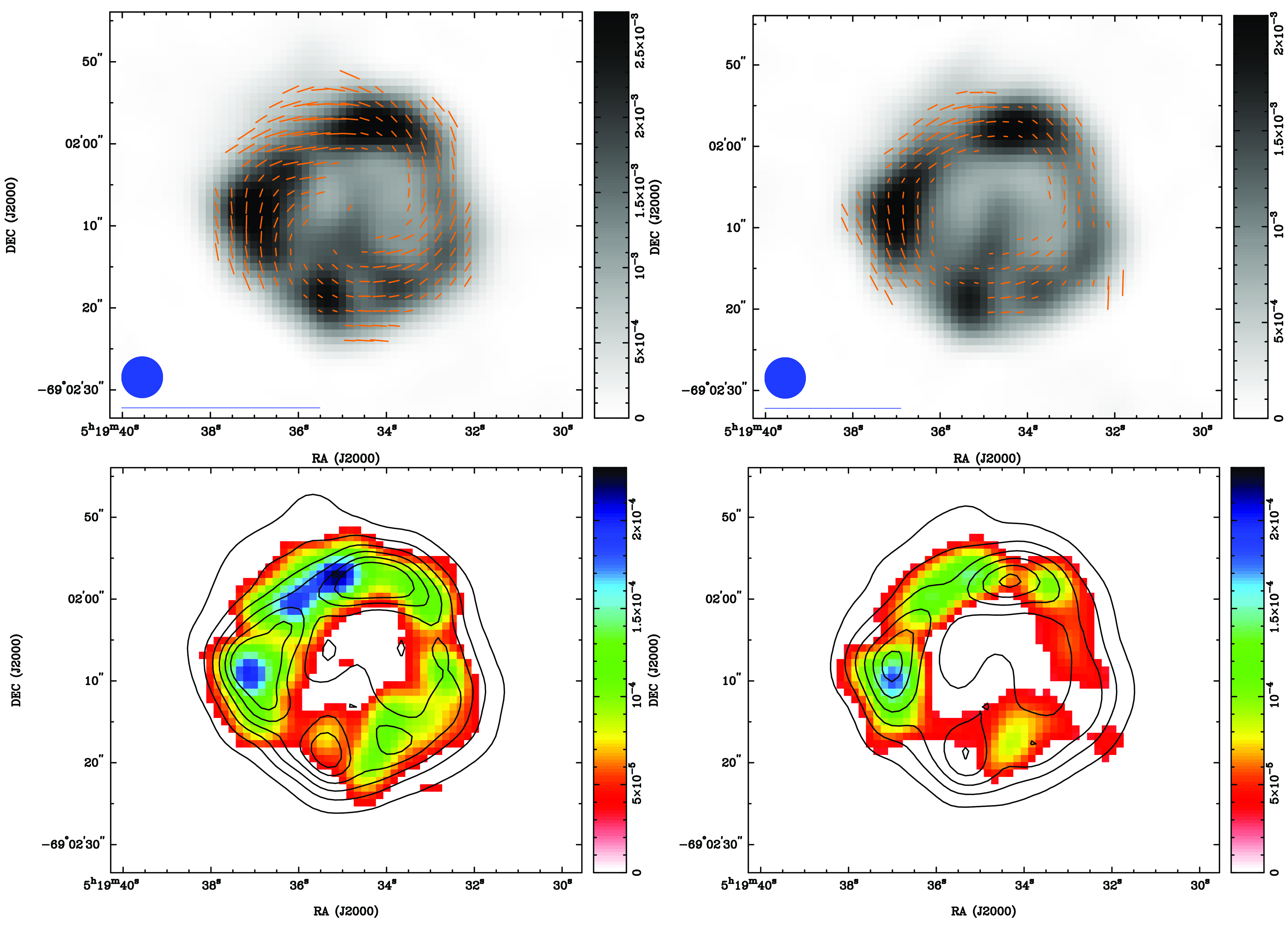
MC SNR J0519–6902 fractional polarisation vectors appear prominent in 5 500 and 9 000 MHz maps (see Figure 3), we also present polarisation intensity maps in the same figure. The average fractional polarisation values are $5\pm1$
% and
$5\pm1$
% and $6\pm1$
% for 5 500 and 9 000 MHz, respectively. These are fractionally lower than the values reported by Bozzetto et al. (Reference Bozzetto, Filipović, Urosevic and Crawford2012) but consistent within the errors, and higher than the values of low frequencies (1 472 and 2 368 MHz) reported by Dickel & Milne (Reference Dickel and Milne1995). They are similar to the values of N 103B of
$6\pm1$
% for 5 500 and 9 000 MHz, respectively. These are fractionally lower than the values reported by Bozzetto et al. (Reference Bozzetto, Filipović, Urosevic and Crawford2012) but consistent within the errors, and higher than the values of low frequencies (1 472 and 2 368 MHz) reported by Dickel & Milne (Reference Dickel and Milne1995). They are similar to the values of N 103B of $\sim$
8% at 5 500 MHz (Alsaberi et al., Reference Alsaberi, Barnes and Filipović2019) in the LMC, Kepler of
$\sim$
8% at 5 500 MHz (Alsaberi et al., Reference Alsaberi, Barnes and Filipović2019) in the LMC, Kepler of $\sim6$
% at 4 835 MHz (DeLaney et al., Reference DeLaney, Koralesky, Rudnick and Dickel2002), and G1.9+0.3 of 6% at 5 500 MHz (De Horta et al., Reference De Horta, Filipovic and Crawford2014) in the MW.
$\sim6$
% at 4 835 MHz (DeLaney et al., Reference DeLaney, Koralesky, Rudnick and Dickel2002), and G1.9+0.3 of 6% at 5 500 MHz (De Horta et al., Reference De Horta, Filipovic and Crawford2014) in the MW.
Fractional Polarisation vectors of MC SNR J0519–6902 overlaid on the intensity ATCA images at 5 500 MHz (upper left) and at 9 000 MHz (upper right). The blue circle in the lower left corner represent a synthesised beam of $5''\times5''$
and the blue line below the circle represents 100% polarisation. The bar on the right side represents the greyscale of the intensity images in Jy beam
$5''\times5''$
and the blue line below the circle represents 100% polarisation. The bar on the right side represents the greyscale of the intensity images in Jy beam $^{-1}$
. Polarisation intensity maps of MC SNR J0519–6902 at 5 500 MHz (bottom left) and at 9 000 MHz (bottom right) are shown at bottom with intensity image contour lines overlaid. Respective contour levels are 0.2, 0.6, 1, 1.4, 1.8, and 2.2 mJy beam
$^{-1}$
. Polarisation intensity maps of MC SNR J0519–6902 at 5 500 MHz (bottom left) and at 9 000 MHz (bottom right) are shown at bottom with intensity image contour lines overlaid. Respective contour levels are 0.2, 0.6, 1, 1.4, 1.8, and 2.2 mJy beam $^{-1}$
for both images. The colour bar represents gradients of polarisation intensity.
$^{-1}$
for both images. The colour bar represents gradients of polarisation intensity.
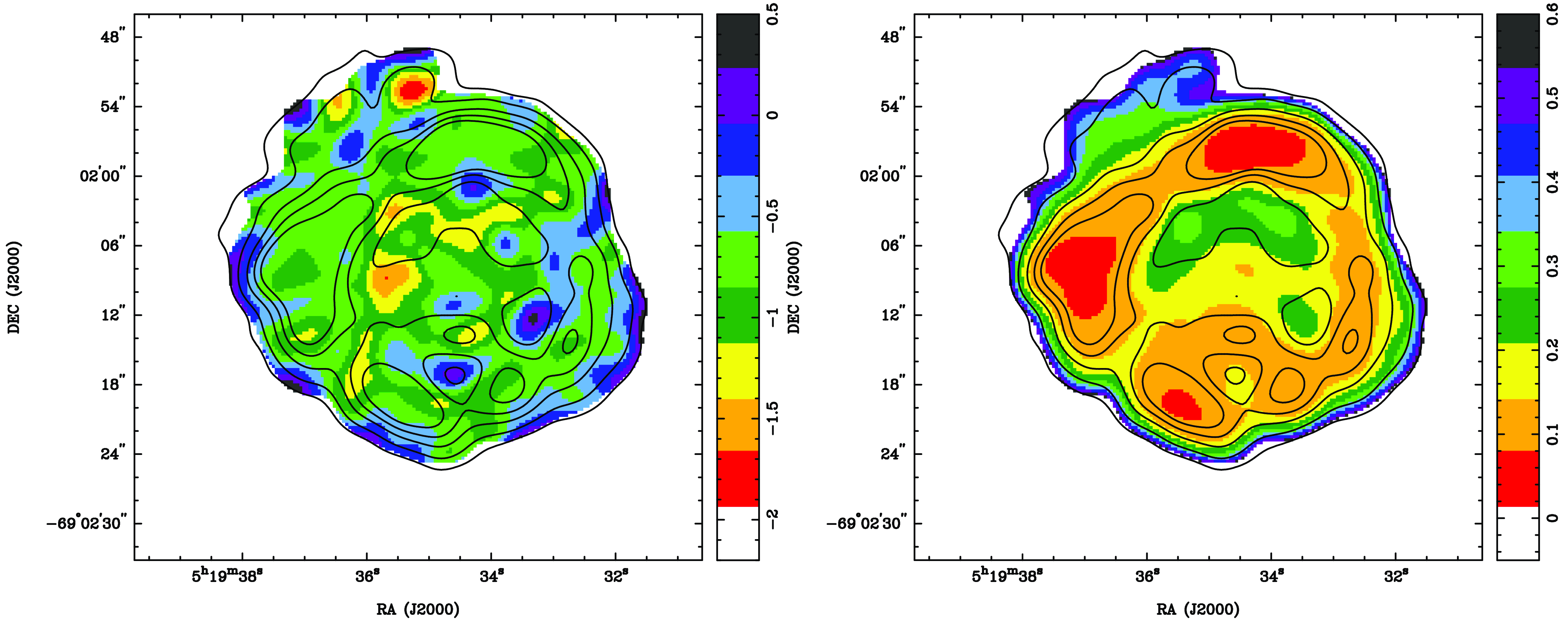
3.3 Spectral index
The radio spectra of MC SNR J0519–6902 can be described as a pure power-law of frequency.
We used the miriad (Sault et al., Reference Sault, Teuben, Wright, Shaw, Payne and Hayes1995) task imfit to extract a total integrated flux density from all available radio continuum observations of MC SNR J0519–6902 listed in Table 2. This includes observations from the Murchison Widefield Array (MWA) (For et al., Reference For, Staveley-Smith and Hurley-Walker2018), Molonglo Observatory Synthesis Telescope (MOST) (Clarke et al., Reference Clarke, Little and Mills1976; Mauch et al., Reference Mauch, Murphy and Buttery2003), Australian Square Kilometre Array Pathfinder (ASKAP) (Pennock et al., Reference Pennock, van Loon and Filipović2021), and ATCA. We measured the MWA flux density for each sub-band (76–227 MHz) and we also re-measured the ASKAP flux density at 888 MHz from Pennock et al. (Reference Pennock, van Loon and Filipović2021). All arrays are sensitive to angular scales much larger than the size of the SNR. Therefore, the sampling of the uv plane for different arrays and at different frequencies would not affect flux density measurements of extended structures. For cross-checking and consistency, we used aegean (Hancock et al., Reference Hancock, Trott and Hurley-Walker2018) and found no significant difference in integrated flux density estimates. Namely, we measured MC SNR J0519–6902 local background noise (1 $\sigma$
) and carefully selected the exact area of the SNR which also excludes all obvious unrelated point sources. We then estimated the sum of all brightnesses above 5
$\sigma$
) and carefully selected the exact area of the SNR which also excludes all obvious unrelated point sources. We then estimated the sum of all brightnesses above 5 $\sigma$
of each individual pixel within that area and converted it to SNR integrated flux density following (Findlay, Reference Findlay1966, Equation 24). We also estimate that the corresponding radio flux density errors are below 10% as examined in our previous work (Filipović et al., Reference Filipović, Payne and Alsaberi2022; Bozzetto et al., Reference Bozzetto, Filipović and Sano2023).
$\sigma$
of each individual pixel within that area and converted it to SNR integrated flux density following (Findlay, Reference Findlay1966, Equation 24). We also estimate that the corresponding radio flux density errors are below 10% as examined in our previous work (Filipović et al., Reference Filipović, Payne and Alsaberi2022; Bozzetto et al., Reference Bozzetto, Filipović and Sano2023).
In Figure 4, we present the flux density vs. frequency graph for MC SNR J0519–6902. The relative errors are used for the error bars on a logarithmic plot. The best power-law weighted least-squares fit is shown (thick red line), with the spatially integrated spectral index $\langle\alpha\rangle= {-0.62 \pm 0.02}$
; slightly steeper but within range when compared to Bozzetto et al. (Reference Bozzetto, Filipović, Urosevic and Crawford2012). This spectral index is consistent with values of similar aged SNRs such as Kepler (–0.64, Dickel et al., Reference Dickel, Sault, Arendt, Matsui and Korista1988) and SN 1006 (–0.6, Gardner & Milne, Reference Gardner and Milne1965) within the MW.
$\langle\alpha\rangle= {-0.62 \pm 0.02}$
; slightly steeper but within range when compared to Bozzetto et al. (Reference Bozzetto, Filipović, Urosevic and Crawford2012). This spectral index is consistent with values of similar aged SNRs such as Kepler (–0.64, Dickel et al., Reference Dickel, Sault, Arendt, Matsui and Korista1988) and SN 1006 (–0.6, Gardner & Milne, Reference Gardner and Milne1965) within the MW.
We also produced a spectral index map using 5 500 and 9 000 MHz images. To create this, all images were first re-gridded to the finest pixel size ( $0.26''\times0.26''$
) using the miriad task regrid. The images were then smoothed to a common resolution (
$0.26''\times0.26''$
) using the miriad task regrid. The images were then smoothed to a common resolution ( $3''\times3''$
) using convol. Finally, maths was applied to create the spectral index map and its corresponding error map as shown in Figure 5. The average spectral index value across the remnant was found to be
$3''\times3''$
) using convol. Finally, maths was applied to create the spectral index map and its corresponding error map as shown in Figure 5. The average spectral index value across the remnant was found to be ${-0.7\pm0.2}$
. We note that the uncertainty value is an order of magnitude higher than the estimate from Figure 4. This is because the error map of spectral index was generated using only two images (5 500 and 9 000 MHz).
${-0.7\pm0.2}$
. We note that the uncertainty value is an order of magnitude higher than the estimate from Figure 4. This is because the error map of spectral index was generated using only two images (5 500 and 9 000 MHz).
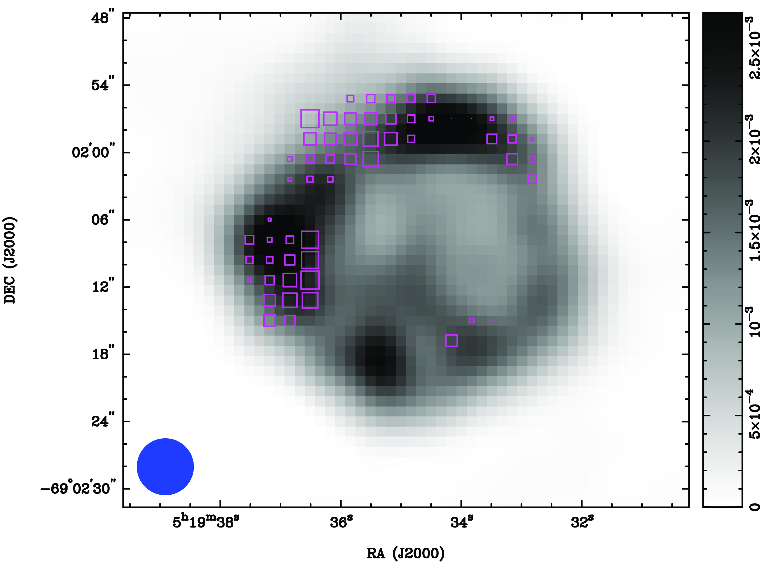
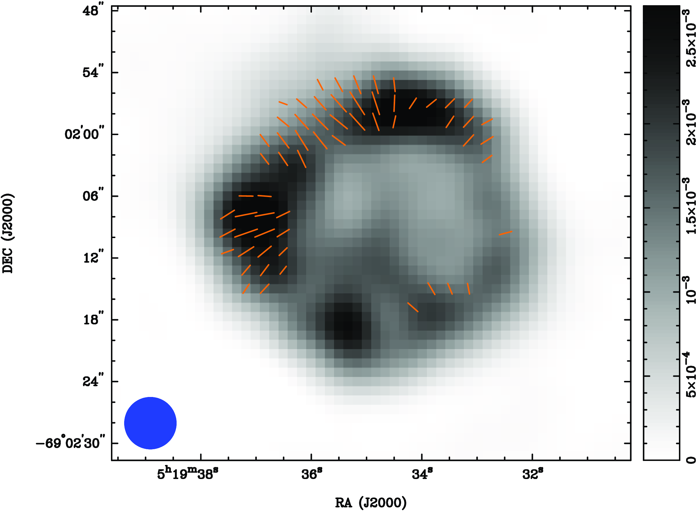
3.4 Rotation measure and magnetic field
To calculate the RM of MC SNR J0519–6902, the 2 048 MHz bandwidth at 5 500 MHz was split into four 512 MHz sub-bands (4 723, 5 244, 5 756, and 6 268 MHz). Using position angle measurements associated with fractional polarisation maps for these frequencies, the miriad task imrm was applied. RM values with an error $\geq$
120 rad m
$\geq$
120 rad m $^{-2}$
were flagged. The resulting RM map is shown in Figure 6. We note the RM values are mostly negative with some positive values towards the north and west of the remnant. Values of RM are concentrated in three areas of the remnant; north-east, north, and north-west (see Figure 6), with an average value of
$^{-2}$
were flagged. The resulting RM map is shown in Figure 6. We note the RM values are mostly negative with some positive values towards the north and west of the remnant. Values of RM are concentrated in three areas of the remnant; north-east, north, and north-west (see Figure 6), with an average value of ${-124\pm83}$
rad m
${-124\pm83}$
rad m $^{-2}$
, different than the value reported by Bozzetto et al. (Reference Bozzetto, Filipović, Urosevic and Crawford2012). Once the RM had been determined, the vectors were rotated back to their intrinsic (zero wavelength) values. In Figure 7 an additional 90
$^{-2}$
, different than the value reported by Bozzetto et al. (Reference Bozzetto, Filipović, Urosevic and Crawford2012). Once the RM had been determined, the vectors were rotated back to their intrinsic (zero wavelength) values. In Figure 7 an additional 90 $^\circ$
was added to the electric vectors so that the vectors represent the direction of magnetic-fields within the remnant. These vectors are oriented in a radial direction (see Figure 7), as expected from a young SNR.
$^\circ$
was added to the electric vectors so that the vectors represent the direction of magnetic-fields within the remnant. These vectors are oriented in a radial direction (see Figure 7), as expected from a young SNR.
To calculate the electron density ( $n_e$
) for MC SNR J0519–6902, we used Equation 2, where EM is the emission measure in cm
$n_e$
) for MC SNR J0519–6902, we used Equation 2, where EM is the emission measure in cm $^{-3}$
, D is the distance to the SNR;
$^{-3}$
, D is the distance to the SNR; $n_e$
and
$n_e$
and $n_p$
are electron and proton densities, respectively.
$n_p$
are electron and proton densities, respectively.
 \begin{equation} EM = \int n_e * n_p\;dV/(4\pi D^2) ,\end{equation}
By assuming $n_e = 1.2\,n_p$
, a volume filling factor = 1, an isotropic and spherical distribution of ionised gas, and using an
$n_e = 1.2\,n_p$
, a volume filling factor = 1, an isotropic and spherical distribution of ionised gas, and using an $EM\sim\! 22.5 \times 10^{58}$
cm
$EM\sim\! 22.5 \times 10^{58}$
cm $^{-3}$
(Maggi et al., Reference Maggi, Haberl and Kavanagh2016), we obtain
$^{-3}$
(Maggi et al., Reference Maggi, Haberl and Kavanagh2016), we obtain $n_e = 6.8\,cm^{-3}$
.
$n_e = 6.8\,cm^{-3}$
.
The magnetic field strength can be estimated using the Equation for Faraday depthFootnote g:
 \begin{equation} RM=811.9\int_{0}^{L}n_{e}B_{\parallel}dl ,\end{equation}
where RM is the rotation measure in rad m $^{-2}$
,
$^{-2}$
, $n_e$
is the electron density in cm
$n_e$
is the electron density in cm $^{-3}$
,
$^{-3}$
, $B_{\parallel}$
is the line of sight magnetic field strength in
$B_{\parallel}$
is the line of sight magnetic field strength in $\mu$
G, and L is the path length through the Faraday rotating medium in kpc (Clarke, Reference Clarke2004).
$\mu$
G, and L is the path length through the Faraday rotating medium in kpc (Clarke, Reference Clarke2004).
Using our average value of RM (–124 rad m $^{-2}$
), an SNR thickness (L) of the compressed shell of
$^{-2}$
), an SNR thickness (L) of the compressed shell of $\sim$
2 pc, and an
$\sim$
2 pc, and an $n_e$
value of 6.8 cm
$n_e$
value of 6.8 cm $^{-3}$
, we obtain an average magnetic field strength of 11.2
$^{-3}$
, we obtain an average magnetic field strength of 11.2 $\mu$
G.
$\mu$
G.
Flux density measurements of MC SNR J0519–6902. The asterisk ( $^{*}$
) indicates that we re-measured this flux density.
$^{*}$
) indicates that we re-measured this flux density.
Radio continuum spectrum of MC SNR J0519–6902. The blue dot indicates that we re-measured this flux density.
The equipartition modelFootnote h can also be used to estimate the magnetic field strength for MC SNR J0519–6902. This method uses modeling and simple parameters to estimate the intrinsic magnetic field strength and energy contained in the magnetic field and cosmic ray (CR) particles using radio synchrotron emission (Arbutina et al., Reference Arbutina, Urošević, Andjelić, Pavlović and Vukotić2012; Arbutina et al., Reference Arbutina, Urošević, Vučetić, Pavlović and Vukotić2013; Urošević et al., Reference Urošević, Pavlović and Arbutina2018).
This approach is purely analytical, described as a rough, only order of magnitude estimate because of assumptions used in analytical derivations and errors in the determination of distance, angular diameter, spectral index, a filling factor, and flux density, tailored especially for the magnetic field strength in SNRs. Arbutina et al. (Reference Arbutina, Urošević, Andjelić, Pavlović and Vukotić2012); Arbutina et al. (Reference Arbutina, Urošević, Vučetić, Pavlović and Vukotić2013); Urošević et al. (Reference Urošević, Pavlović and Arbutina2018) present two models; the difference is in the assumption whether there is equipartition, precisely constant partition with CRs or only CR electrons. Urošević et al. (Reference Urošević, Pavlović and Arbutina2018) showed the latter type of equipartition is a better assumption than the former.
Using the Urošević et al. (Reference Urošević, Pavlović and Arbutina2018) modelFootnote i, the mean equipartition field over the entire remnant is ${72\pm5}$ $\mu$
G with an estimated minimum energy of E
$\mu$
G with an estimated minimum energy of E $_\textrm{min}$
= 2.6
$_\textrm{min}$
= 2.6 $\times10^{48}$
erg. However, using the Arbutina et al. (Reference Arbutina, Urošević, Andjelić, Pavlović and Vukotić2012) earlier model, which assumes CRs composed of electrons, protons, and ions, the estimate is
$\times10^{48}$
erg. However, using the Arbutina et al. (Reference Arbutina, Urošević, Andjelić, Pavlović and Vukotić2012) earlier model, which assumes CRs composed of electrons, protons, and ions, the estimate is ${156\pm5}$ $\mu$
G, with a minimum explosion energy of E
$\mu$
G, with a minimum explosion energy of E $_\textrm{min}$
= 1.2
$_\textrm{min}$
= 1.2 $\times10^{49}$
erg. This is consistent with previous values reported by Bozzetto et al. (Reference Bozzetto, Filipović, Urosevic and Crawford2012).
$\times10^{49}$
erg. This is consistent with previous values reported by Bozzetto et al. (Reference Bozzetto, Filipović, Urosevic and Crawford2012).
Of course, we cannot suppose we know the remnant’s magnetic field to the significant figures implied above as the models do not have any such accuracy. We do feel it is reasonable to say MC SNR J0519–6902’s magnetic field can be estimated between 10 and $10^2$ $\mu$
G. This is consistent with other relatively young Type Ia SNRs including Tycho, Kepler, and SN 1006 (Reynolds & Ellison, Reference Reynolds and Ellison1992).
$\mu$
G. This is consistent with other relatively young Type Ia SNRs including Tycho, Kepler, and SN 1006 (Reynolds & Ellison, Reference Reynolds and Ellison1992).
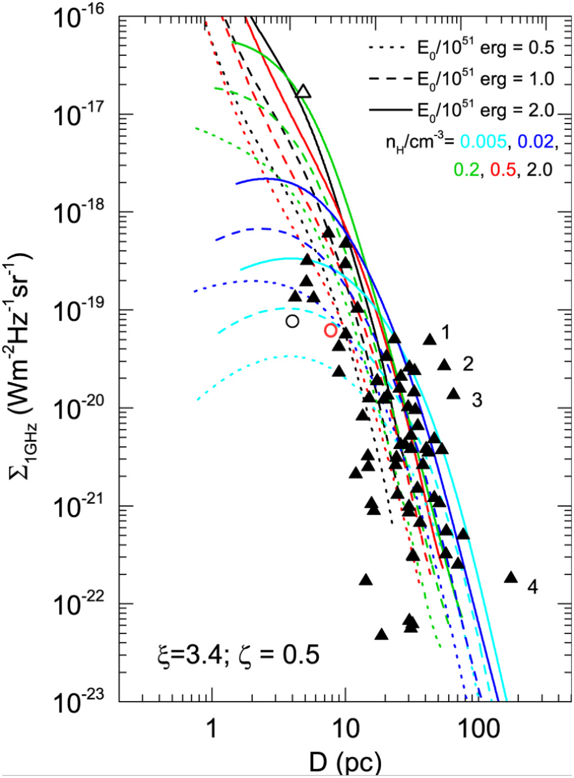
3.5 $\Sigma$
–D relation
$\Sigma$
–D relation

A previous $\Sigma$
–D diagram (Urošević Reference Urošević2022; Urošević, Reference Urošević2020; Pavlović et al., Reference Pavlović, Urošević and Arbutina2018, their Figure 3) was compared with our values, D
$\Sigma$
–D diagram (Urošević Reference Urošević2022; Urošević, Reference Urošević2020; Pavlović et al., Reference Pavlović, Urošević and Arbutina2018, their Figure 3) was compared with our values, D $\sim$
8 pc and
$\sim$
8 pc and $\Sigma_\textrm{1 GHz} =6\times10^{-20}$
W m
$\Sigma_\textrm{1 GHz} =6\times10^{-20}$
W m $^{-2}$
Hz
$^{-2}$
Hz $^{-1}$
sr
$^{-1}$
sr $^{-1}$
, for MC SNR J0519–6902. This comparison implies the MC SNR J0519–6902 is undergoing expansion within a surrounding environment characterised by a low-density of 0.005–0.02 cm
$^{-1}$
, for MC SNR J0519–6902. This comparison implies the MC SNR J0519–6902 is undergoing expansion within a surrounding environment characterised by a low-density of 0.005–0.02 cm $^{-3}$
with an initial energy of explosion of E
$^{-3}$
with an initial energy of explosion of E $_\textrm{ 0}$
=
$_\textrm{ 0}$
= $10^{51}$
erg (Figure 8). MC SNR J0519–6902 position at
$10^{51}$
erg (Figure 8). MC SNR J0519–6902 position at $\Sigma$
–D tracks can set it somewhere at the end of the free expansion phase, close to entering the early Sedov phase of evolution.
$\Sigma$
–D tracks can set it somewhere at the end of the free expansion phase, close to entering the early Sedov phase of evolution.
Left: Spectral index map of SNR MC SNR J0519–6902 created using 5 500 and 9 000 MHz images. Right: Error map of spectral index of SNR MC SNR J0519–6902. Contour lines are overlaid using our ATCA 5 500 MHz image (0.09, 0.2, 0.4, 0.6, and 0.8 mJy beam $^{-1}$
).
$^{-1}$
).
Of course, multiple tracks can correspond to a single SNR on the $\Sigma$
–D plane. Assuming this is a young SNR, it is unlikely that the black and red lines would apply. If the evolutionary tracks are black or red in this position on the
$\Sigma$
–D plane. Assuming this is a young SNR, it is unlikely that the black and red lines would apply. If the evolutionary tracks are black or red in this position on the $\Sigma$
–D diagram, then this SNR would need to be old, which does not fit. Pavlović et al. (Reference Pavlović, Urošević and Arbutina2018) gives an explanation for 1-4 outliers. Alternatively, application of the method from Urošević (Reference Urošević2022, Reference Urošević2020) to determine the evolutionary status of newly detected SNRs, the position on the
$\Sigma$
–D diagram, then this SNR would need to be old, which does not fit. Pavlović et al. (Reference Pavlović, Urošević and Arbutina2018) gives an explanation for 1-4 outliers. Alternatively, application of the method from Urošević (Reference Urošević2022, Reference Urošević2020) to determine the evolutionary status of newly detected SNRs, the position on the $\Sigma$
–D diagram (where a single SNR might align with multiple tracks) must relate to the equipartition magnetic field strength and spectral characteristics. According to the literature, MC SNR J0519–6902 is a young SNR, and its position on the
$\Sigma$
–D diagram (where a single SNR might align with multiple tracks) must relate to the equipartition magnetic field strength and spectral characteristics. According to the literature, MC SNR J0519–6902 is a young SNR, and its position on the $\Sigma$
–D diagram, equipartition strength, and steep spectrum (–0.62) support this classification. In this paper, the evolutionary phase using Urošević (Reference Urošević2022, Reference Urošević2020) is not estimated; instead, assuming it is a young SNR, environmental density is estimated based on the
$\Sigma$
–D diagram, equipartition strength, and steep spectrum (–0.62) support this classification. In this paper, the evolutionary phase using Urošević (Reference Urošević2022, Reference Urošević2020) is not estimated; instead, assuming it is a young SNR, environmental density is estimated based on the $\Sigma$
–D tracks.
$\Sigma$
–D tracks.
3.6 Distribution of H i clouds
The distribution of H i in the LMC velocity range towards MC SNR J0519–6902 is shown in Figure 9a where bright H i clouds lie to the south-east. At this radial velocity from $\sim$
220 to
$\sim$
220 to $\sim$
270 km s
$\sim$
270 km s $^{-1}$
alone, H i gas was predominantly present (see Appendix for details). However, we could not confirm an association because the angular resolution of the H i data is roughly twice the diameter of the SNR. The SNR shell H i integrated intensity is
$^{-1}$
alone, H i gas was predominantly present (see Appendix for details). However, we could not confirm an association because the angular resolution of the H i data is roughly twice the diameter of the SNR. The SNR shell H i integrated intensity is $\sim$
600 K km s
$\sim$
600 K km s $^{-1}$
, corresponding to a column density of
$^{-1}$
, corresponding to a column density of $\sim1 \times 10^{21}$
cm
$\sim1 \times 10^{21}$
cm $^{-2}$
under an optically thin assumption (e.g., Dickey & Lockman, Reference Dickey and Lockman1990).
$^{-2}$
under an optically thin assumption (e.g., Dickey & Lockman, Reference Dickey and Lockman1990).
Rotation measure boxes of MC SNR J0519–6902 (ATCA; 4 723, 5 244, 5 756, and 6 268 MHz) overlaid on the ATCA image at 5 500 MHz (greyscale). Most boxes are open (negative values), ranging from a minimum of –314 rad m $^{-2}$
to a maximum of 33 rad m
$^{-2}$
to a maximum of 33 rad m $^{-2}$
. The blue circle in the lower left corner represents a synthesised beam of
$^{-2}$
. The blue circle in the lower left corner represents a synthesised beam of $5''\times5''$
. The bar on the right side represents the greyscale of the 5 500 MHz ATCA image in Jy beam
$5''\times5''$
. The bar on the right side represents the greyscale of the 5 500 MHz ATCA image in Jy beam $^{-1}$
.
$^{-1}$
.
Magnetic field direction vectors of MC SNR J0519–6902 overlaid on the ATCA image at 5 500 MHz (greyscale). The blue circle in the lower left corner represents a synthesised beam of $5''\times5''$
. The bar on the right side represents the greyscale of the 5 500 MHz ATCA image in Jy beam
$5''\times5''$
. The bar on the right side represents the greyscale of the 5 500 MHz ATCA image in Jy beam $^{-1}$
.
$^{-1}$
.
Radio surface brightness–to–diameter diagram for SNRs at a frequency of 1 GHz (black triangles), obtained from numerical simulations (Pavlović et al., Reference Pavlović, Urošević and Arbutina2018, their Figure 3). MC SNR J0519–6902 is marked with an open red circle while the open triangle represents Cassiopeia A. The open black circle represents the youngest Galactic SNR, G1.9+0.3 (Luken et al., Reference Luken, Filipović and Maxted2020). Numbers represent the following SNRs: (1) CTB 37A, (2) Kes 97, (3) CTB 37B, and (4) G65.1+0.6.
(a) Integrated intensity map of H i towards MC SNR J0519–6902. The integrated velocity range is from 214.5 to 269.7 km s $^{-1}$
. The superposed contours are the same as shown in Figure 1a. (b) Position–velocity diagram of H i. The integrated Declination range is from
$^{-1}$
. The superposed contours are the same as shown in Figure 1a. (b) Position–velocity diagram of H i. The integrated Declination range is from $-$
69.04
$-$
69.04 $^{\circ}$
to
$^{\circ}$
to $-$
69.03
$-$
69.03 $^{\circ}$
. The dashed curve in the position–velocity diagram indicates the boundary of the H i cavity (see Section 3.6).
$^{\circ}$
. The dashed curve in the position–velocity diagram indicates the boundary of the H i cavity (see Section 3.6).
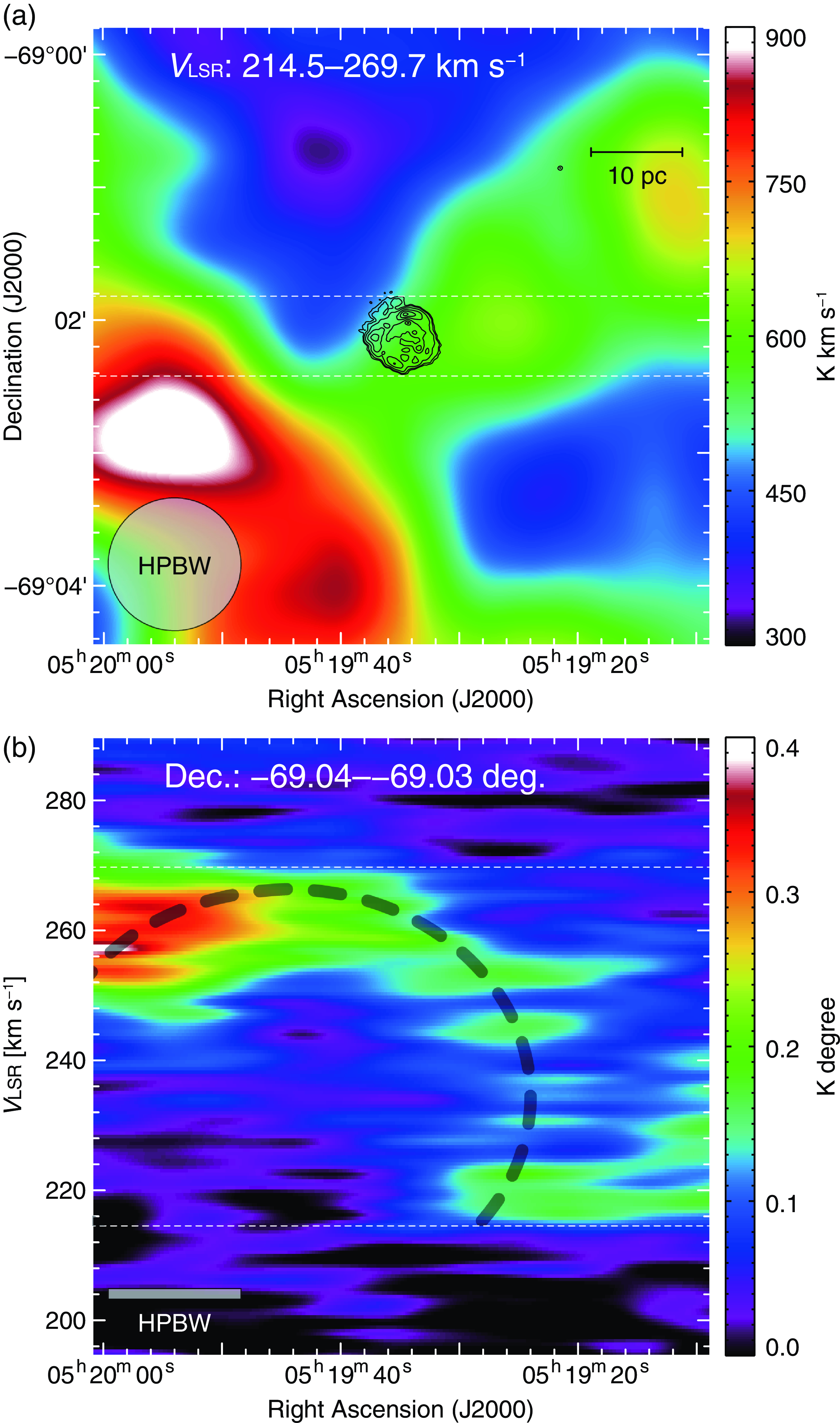
Figure 9b shows a position–velocity diagram centred near the SNR shell on the edge of an incomplete cavity-like structure of H i that spans a diameter of $\sim$
50 pc and a velocity of
$\sim$
50 pc and a velocity of $\sim$
30 km s
$\sim$
30 km s $^{-1}$
, respectively. MC SNR J0519–6902 possibly exploded at the edge of what may be a wind bubble that might have originated from a fast outflow driven from an accreting white dwarf (WD); similar to that proposed for Tycho (Zhou et al., Reference Zhou, Chen and Zhang2016; Tanaka et al., Reference Tanaka, Okuno and Uchida2021) and N 103B (Sano et al., Reference Sano, Yamane and Tokuda2018). Using a model from Leahy (Reference Leahy2017) having an updated radius of 3.6 pc in a wind environment, we find new ages with the same model between 250 and 1,100 yrs for various values of the ejecta density profile index (
$^{-1}$
, respectively. MC SNR J0519–6902 possibly exploded at the edge of what may be a wind bubble that might have originated from a fast outflow driven from an accreting white dwarf (WD); similar to that proposed for Tycho (Zhou et al., Reference Zhou, Chen and Zhang2016; Tanaka et al., Reference Tanaka, Okuno and Uchida2021) and N 103B (Sano et al., Reference Sano, Yamane and Tokuda2018). Using a model from Leahy (Reference Leahy2017) having an updated radius of 3.6 pc in a wind environment, we find new ages with the same model between 250 and 1,100 yrs for various values of the ejecta density profile index ( $r^{-n}$
with
$r^{-n}$
with $n=6$
to 14), compared to
$n=6$
to 14), compared to $\sim 2\,700$
yrs for a uniform circumstellar medium.
$\sim 2\,700$
yrs for a uniform circumstellar medium.
At the same time, the tentative bubble may not originate from the progenitor star(s). Those winds eject of order one solar mass of material at low velocities with low energy. The H i bubble has a size of 30 pc at the distance of the LMC. We use Kwok (Reference Kwok2007) to calculate the radius and mass of the swept-up H i shell. Using his Equation (16.62), we obtain the shell radius of 1.9 pc for a wind speed of 20 km s $^{-1}$
, ISM density of 1 cm
$^{-1}$
, ISM density of 1 cm $^{-3}$
and wind duration of 1 Myrs and 55 pc for a duration of 100 Myrs. The mass of the H i shell would be 0.8 M
$^{-3}$
and wind duration of 1 Myrs and 55 pc for a duration of 100 Myrs. The mass of the H i shell would be 0.8 M $_\odot$
and 2
$_\odot$
and 2 $\times 10^{4}$
M
$\times 10^{4}$
M $_\odot$
for duration of 1 and 100 Myrs, respectively. The mass of the partial shell feature that is visible in H i in Figure 9b is estimated by integrating the H i over velocity and over the area of the shell (with radius
$_\odot$
for duration of 1 and 100 Myrs, respectively. The mass of the partial shell feature that is visible in H i in Figure 9b is estimated by integrating the H i over velocity and over the area of the shell (with radius $\sim$
30 pc). The resulting mass in the feature is
$\sim$
30 pc). The resulting mass in the feature is $\sim$
2.5 M
$\sim$
2.5 M $_{\odot}$
, which is consistent with the theoretical estimate above if the duration of the wind is
$_{\odot}$
, which is consistent with the theoretical estimate above if the duration of the wind is $\sim$
3 million yrs. The radius of a shell expanding at 10 km s
$\sim$
3 million yrs. The radius of a shell expanding at 10 km s $^{-1}$
for 3 million yrs is 30 pc, consistent with a low-mass stellar wind origin of the shell. In any case, further H i studies with higher angular resolutions are needed to confirm this scenario for MC SNR J0519–6902.
$^{-1}$
for 3 million yrs is 30 pc, consistent with a low-mass stellar wind origin of the shell. In any case, further H i studies with higher angular resolutions are needed to confirm this scenario for MC SNR J0519–6902.
4. Conclusion
We have presented a new radio continuum study of LMC SNR MC SNR J0519–6902. We hypothesise the following:
-
• MC SNR J0519–6902’s polarisation is similar to younger remnants (order
$10^2$
years) N 103B in the LMC, and, Kepler and G1.9+0.3 in the MW Galaxy. Our remnant has an average fractional polarisation of
$5\pm1$
% and
$6\pm1$
% at 5 500 and 9 000 MHz, respectively. -
• MC SNR J0519–6902 has a spectral index of
${-0.62\pm0.02}$
, similar to those of other younger remnants including Kepler and SN 1006. -
• We find estimates of the magnetic field strength of this remnant based on our data to be on the order of between 10 and 100
$\mu$
G, again similar to younger remnants including Kepler and Tycho. -
• Based on MC SNR J0519–6902’s position on our
$\Sigma$
-D track and its age as a young remnant, we suggest it may be at the end of its free expansion phase, entering the Sedov phase of evolution. -
• The possible existence of a H i cloud towards the south-east of the remnant and a suspected wind-bubble cavity in this region.


Acknowledgment
The Australian Compact Array is part of the Australian Telescope which is funded by the Commonwealth of Australia for operation as National Facility managed by Australian Commonwealth Scientific and Industrial Research Organisation (CSIRO). This paper includes archived data obtained through the ATOA (http://atoa.atnf.csiro.au). We used the karma and miriad software packages developed by the ATNF. MDF and GR acknowledge ARC funding through grant DP200100784. D.U. acknowledges the Ministry of Education, Science and Technological Development of the Republic of Serbia through contract No. 451-03-68/2022-14/200104, and for the support through the joint project of the Serbian Academy of Sciences and Arts and Bulgarian Academy of Sciences on the detection of extragalactic SNRs and H ii regions. H.S. was also supported by JSPS KAKENHI grant Nos. 19K14758, 21H01136, and 24H00246.
Data Availability
We utilised archival data from the Australia Telescope Compact Array (ATCA), obtained via the online archives of the Australia Telescope National Facility (ATNF)Footnote j. The X-ray broadband image was derived from the Chandra Data Archive (CDA) dataFootnote k. Additionally, optical HST image was downloaded from the Mikulski Archive for Space Telescope (MAST)Footnote l.
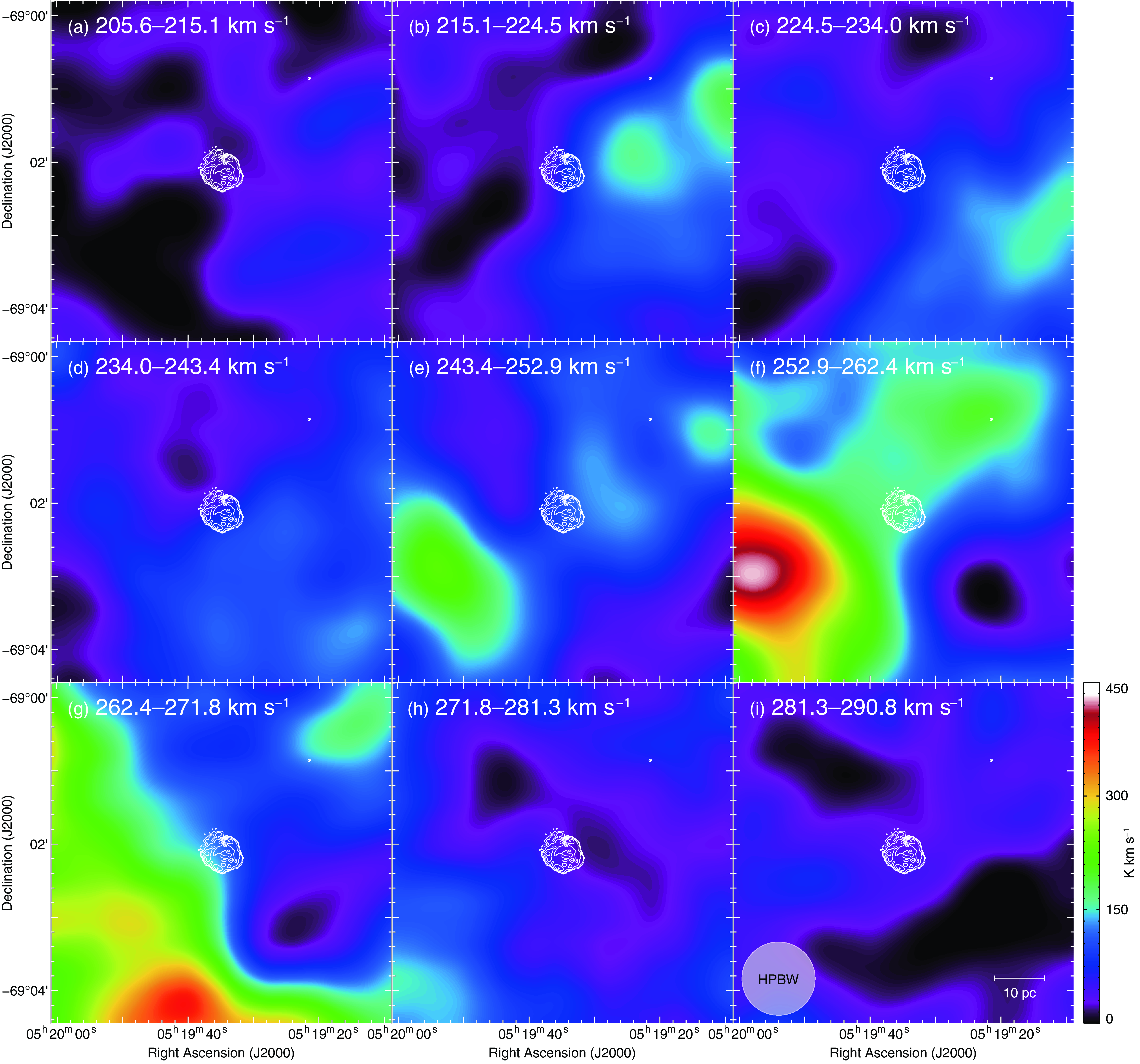
Appendix A. Velocity channel distributions of H i
Figure A1 shows the velocity channel distributions of H i toward MC SNR J0519–6902. We found H i emission only in the velocity range from $\sim$
220 to
$\sim$
220 to $\sim$
270 km s
$\sim$
270 km s $^{-1}$
. Although we could not confirm the cloud association with the SNR due to the modest angular resolution of the H i data, we can infer that the SNR exploded in a relatively low-density gas environment. Further H i observations with high-angular resolution are needed to investigate whether the H i clouds are physically associated with the SNR.
$^{-1}$
. Although we could not confirm the cloud association with the SNR due to the modest angular resolution of the H i data, we can infer that the SNR exploded in a relatively low-density gas environment. Further H i observations with high-angular resolution are needed to investigate whether the H i clouds are physically associated with the SNR.
Velocity channel distributions of H i toward MC SNR J0519–6902. The superposed contours are the same as those shown in Figure 1. Each panel shows H i distributions every 9.4 km s $^{-1}$
in a velocity range from 205.6 to 290.8 km s
$^{-1}$
in a velocity range from 205.6 to 290.8 km s $^{-1}$
.
$^{-1}$
.


 Open access