


1. Introduction and background
This paper explores the use of low-fidelity prototyping and wayfaring as design tools through a case study. The method is used to reduce uncertainty and iteratively shape requirements for a complex optical mechanism in NewSpace projects.
Recent years have seen an increase in the development and launch of space and satellite technology (Reference MathieuMathieu, 2024). Previously, this development was reserved for national space agencies. The introduction of modularity in space with the CubeSat platform in 1999, later technology development, lower launch cost, and the use of commercial off-the-shelf (COTS) components, have enabled new players, such as startups, universities, and small and medium enterprises, to utilize space (Reference Ferrara, Cicconi, Minotti, Trovato and CaputoFerrara et al., 2025). This new paradigm in space design is called NewSpace, and Reference Ferrara, Cicconi, Minotti, Trovato and CaputoFerrara et al. (2025) write in their NewSpace engineering design literature review, “There is a growing need for up-to-date metrics and tools that can guide system design from the early stages […], to define development plans and evaluate strategic directions”. This paper, therefore, explores design methods in the NewSpace era through a case study of the design of the in-orbit telescope focus and deployment mechanism for the next hyperspectral imaging satellite payload, following a case study research design (Reference EisenhardtEisenhardt, 1989). This single-case study is used to build theory and evaluate design tools through process tracing across iterations. The paper first describes the differences between “Old Space” and NewSpace, then presents a case study using 23 low-fidelity prototypes, and analyzes how changes in prototype fidelity relate to the emergence, refinement, and validation of requirements in a NewSpace context.
1.1. Traditional design methods and NewSpace
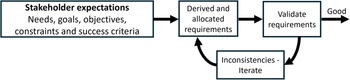
The traditional space industry, often called “Old Space”, is dominated by large, high-stakes missions led by national space agencies (Reference Ferrara, Cicconi, Minotti, Trovato and CaputoFerrara et al., 2025; Reference PaikowskyPaikowsky, 2017). These programs follow classical systems engineering: mission-criticality, long lifetimes, and multi-partner integration motivate stringent requirements and a phase-gated, requirements-driven development path (ECSS, 2022; NASA, 2019). In the NASA Systems Engineering Handbook, stakeholder expectations are turned into a “complete set of validated technical requirements” before they are decomposed and used as inputs to the Design Solution Definition Process. Requirements and architectures are then baselined and placed under configuration control as the system is refined, which is effective for stable concepts of operations but tends to increase design inertia and the cost of change over time (Reference Mavris, DeLaurentis, Bandte and HaleMavris et al., 1998). The requirement definition phase is shown in Figure 1 (NASA, 2019). The concept of operation can also be iterated if necessary.
The requirements definition phase of the System Design Processes from the NASA Systems Engineering Handbook (NASA, 2019)
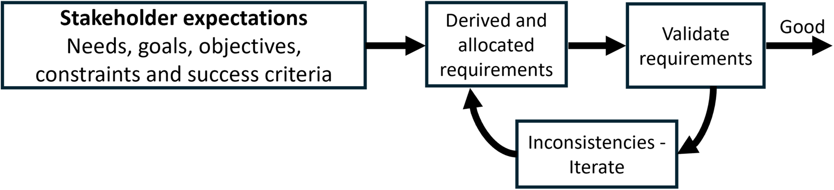
For projects with high early uncertainty, this front-loaded emphasis on requirements can slow physical learning and constrain design freedom, motivating alternative, prototype-driven approaches (Reference Kriesi, Blindheim, Bjelland and SteinertKriesi et al., 2016). In recent years, the development strategy in the space ecosystem has pivoted toward NewSpace, with design enablers such as rapid prototyping and COTS components to meet design drivers like cost reduction and short time-to-market (Reference Ferrara, Cicconi, Minotti, Trovato and CaputoFerrara et al., 2025). Previous studies have examined rapid prototyping and multidisciplinary design; however, this was done at a more mature stage of development (Reference Higdon and KlausHigdon & Klaus, 2012). Reference Ferrara, Cicconi, Minotti, Trovato and CaputoFerrara et al. (2025) characterize the design drivers and enablers at a conceptual level, explicitly aiming to provide a high-level baseline for early NewSpace system design rather than mechanism-level methods. At this level of abstraction, prototyping appears as one enabler among many, and the review offers little empirical detail on how physical prototypes are actually used to uncover unknowns in concrete projects. In fact, only a single study on rapid prototyping (Reference SiddiqueSiddique, 2024) is cited. Building on this high-level map, the present paper contributes a detailed design case, showing how low-fidelity prototypes and managed fidelity changes shape requirements and architecture for a CubeSat telescope focus mechanism. Specifically, this paper aims to address the following research question: How can low-fidelity, wayfaring-based prototyping be used to turn early uncertainty into validated requirements for a NewSpace telescope focus mechanism?
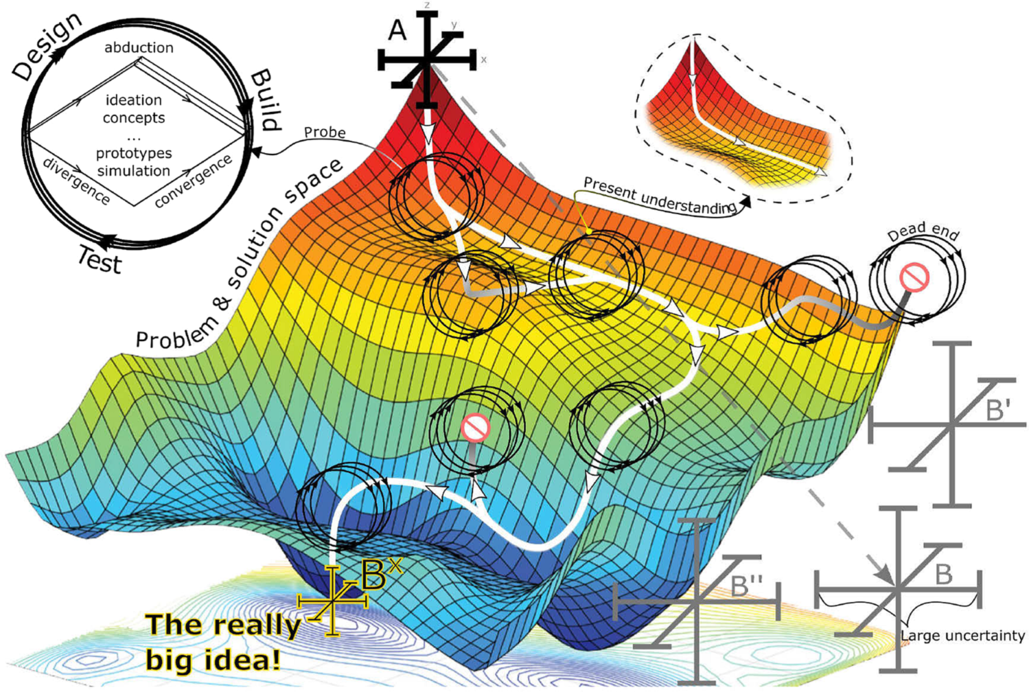
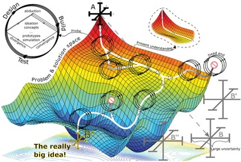
Early-stage product development often faces a “fuzzy front end” where product requirements and technologies are not yet well-defined (Reference Elverum, Welo and SteinertElverum et al., 2015). Prototyping can be effective for handling changing requirements (Reference Kriesi, Blindheim, Bjelland and SteinertKriesi et al., 2016), uncovering unknown unknowns (Reference Leifer and SteinertLeifer & Steinert, 2011), informing decision-making, easing interdisciplinary communication (Reference Buchenau and SuriBuchenau & Suri, 2000; Reference WangWang, 2024), and reducing the risk of unforeseen challenges during later development stages. Low-fidelity prototypes are simplified prototypes that demonstrate a product’s core functionality (Reference Houde and HillHoude & Hill, 1997; Reference WangWang, 2024). Prototype resolution is the “amount of detail” a prototype has (Reference Houde and HillHoude & Hill, 1997). An effective design method in the fuzzy front end is wayfaring, in which the design space is explored through iterative learning prototypes within a design-build-test cycle (Reference Steinert and LeiferSteinert & Leifer, 2012; Reference VestadVestad, 2022). An abstraction of the method (Reference KohtalaKohtala, 2023), modified from (Reference Steinert and LeiferSteinert & Leifer, 2012) based on machine learning convergence, is shown in Figure 2.
Wayfaring uses prototypes to reveal new information, turning unknown unknowns into known knowns, allowing requirements to solidify dynamically. Because the telescope focus mechanism case involved many unknowns, the design team adopted a wayfaring process in which simple, low-cost prototypes are used to surface unknowns, expose dominant constraints, and convert vague goals into concrete, testable requirements. Attempting to freeze a full requirement set at the outset would not have benefited the project at this stage, because time spent researching and defining requirements could be spent learning and solving the problem. This is done to avoid a common decision-making pitfall, paralysis by analysis, in which extended analysis and information gathering delay or prevent concrete prototyping and decision-making. Instead, the approach reduces the cost of being wrong, preserves momentum, and anchors decisions in prototypes rather than assumptions.
Adapted wayfaring methodology (Reference KohtalaKohtala, 2023), based on (Reference Steinert and LeiferSteinert & Leifer, 2012). The iterations aim to find a global minimum, i.e., the best solution, as in machine learning convergence
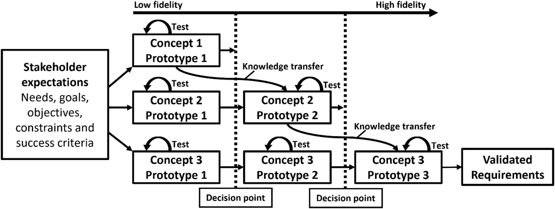
The method chosen for this design development starts with the same initial conditions as the process shown in Figure 1; however, different concepts were developed and subsequently iterated on in several prototypes. Stakeholder expectations were not requirements, but goals like “adjust focus reliably within the available satellite”, not detailed specifications. Multiple concepts are then pursued in parallel at low-fidelity, but at medium to high resolution (Reference Houde and HillHoude & Hill, 1997). Each lane starts with a quickly built Prototype 1 that answers a narrow feasibility question, such as actuator packaging or redundancy level. Prototypes are fabricated in hours using rapid tools such as 3D printing and laser cutting, and are tested immediately. Results determine whether a lane iterates or is stopped; weak lanes are terminated early, while promising ones advance. Knowledge, such as mounting and tolerances, is transferred from different concepts over to the subsequent prototypes with higher fidelity. This abstraction of a discrete parallel wayfaring is illustrated in Figure 3.
Parallel discrete wayfaring with decision points. Each concept lane is tested iteratively; outcomes are increased fidelity, iteration at similar fidelity, or termination. Learning transfers across lanes as relevant, thus converging design goals toward validated requirements
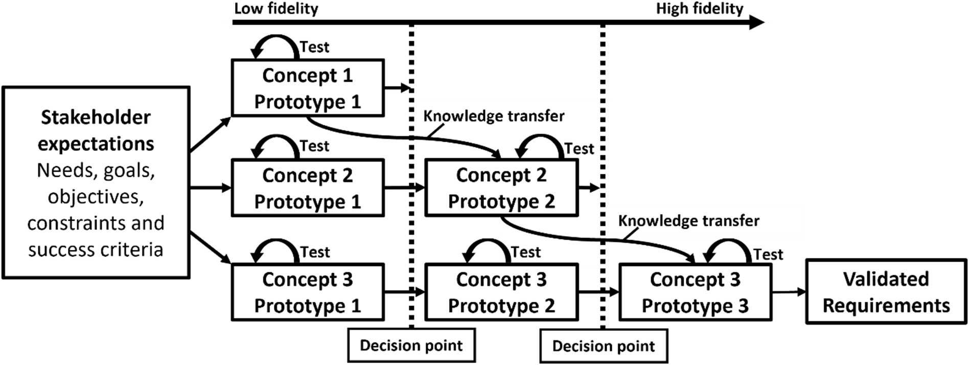
Figure 3 Long description
The flowchart illustrates the process of parallel discrete wayfaring with decision points in early-stage product development. It starts with stakeholder expectations, which include needs, goals, objectives, constraints, and success criteria. This leads to the creation of three initial prototypes: Concept 1 Prototype 1, Concept 2 Prototype 1, and Concept 3 Prototype 1. Each prototype is tested iteratively. Knowledge transfer occurs between Concept 2 Prototype 1 and Concept 2 Prototype 2, and between Concept 3 Prototype 1 and Concept 3 Prototype 2. Each concept lane can result in increased fidelity, iteration at similar fidelity, or termination. The process involves decision points where the outcomes are evaluated. Concept 3 Prototype 2 leads to Concept 3 Prototype 3, which eventually results in validated requirements.
Rapid prototyping requires a modular, platform-based design to create interchangeable modules and standard interfaces, enabling testing multiple ideas quickly without having to start from scratch each time (Reference SiddiqueSiddique, 2024). Additionally, leveraging additive manufacturing (AM), laser cutting, and other rapid-fabrication tools is key for low-fidelity prototyping (Reference WangWang, 2024).
2. Case study: CubeSat telescope focus mechanism challenges
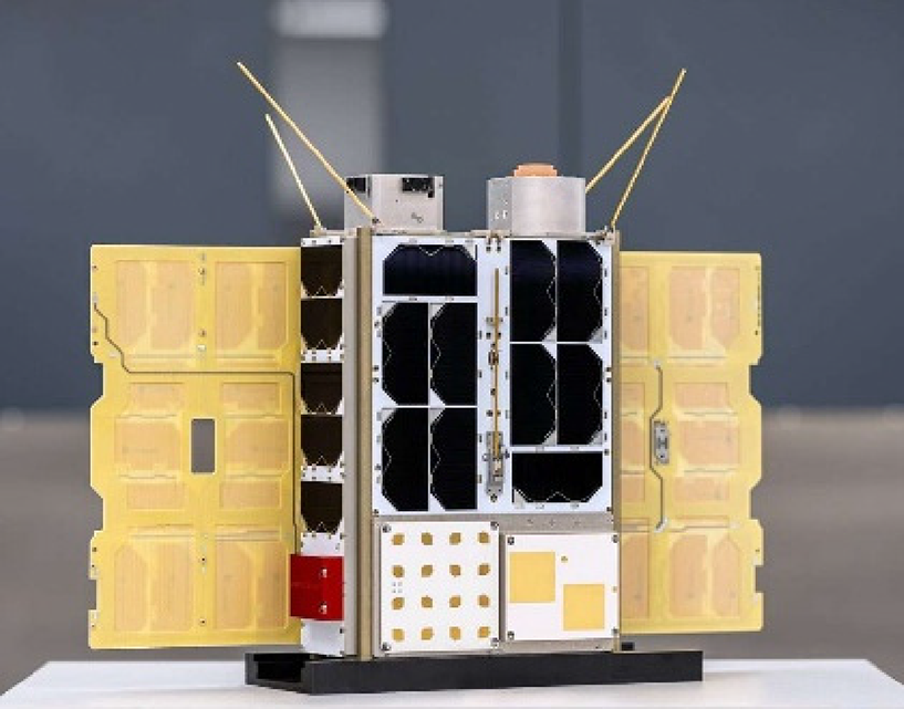
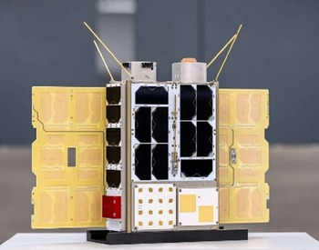
The successful launch and deployment of HYPSO (HYPerspectral Small satellite for ocean Observation) 1 and 2 demonstrate the feasibility of hyperspectral imaging (HSI) for Earth observation using COTS components (Reference Bakken, Henriksen, Birkeland, Langer, Oudijk, Berg, Pursley, Garrett, Gran-Jansen, Honoré-Livermore, Grøtte, Kristiansen, Orlandic, Gader, Sørensen, Sigernes, Johnsen and JohansenBakken et al., 2023). The HYPSO 2 satellite is shown in Figure 4. These satellites monitor water quality along the Norwegian coast with a ground sampling distance (GSD) of 150 m, meaning each pixel is 150 m. For the next HYPSO mission, imaging inland waters requires a GSD of around 10 m with a good signal-to-noise ratio. This probably necessitates a large-aperture front lens. Refractive front lenses are heavy and not readily available in the required size. Reflective telescopes are a good option for this, but lack the mechanical rigidity for space launch (Reference Sigernes, Øvrebø, Hole, Hauge, Steinert, Bakken, Garrett, Birkeland, Skauli and JohansenSigernes et al., 2025). In addition, such large structures occupy substantial volume, reduce the system’s natural frequencies, increase the risk of resonances, and are more prone to thermally induced defocusing, necessitating an adjustment mechanism.
The HYPSO 2 satellite launched in August 2024
This research, therefore, aims to enable the adoption of a COTS telescope for the next HYPSO payload. Despite a concrete problem space, a large solution space remains. To enable modification and testing, a COTS Celestron C6 telescope (Ø180×406 mm) was used for the optical elements in this study, as it likely has the best optical parameters for this problem (Reference Sigernes, Øvrebø, Hole, Hauge, Steinert, Bakken, Garrett, Birkeland, Skauli and JohansenSigernes et al., 2025). This system requires a secondary-mirror focus mechanism and is therefore used as the case study in this paper.
Because the payload was co-evolving with the bus, the front end was fuzzy: final packaging and interfaces (electronics, ADCS, antennas, baffles), the true focus/collimation shift through launch/thermal cycles, and the actuation stroke, step size, stiffness, and backlash limits were all uncertain. In addition, the team had little experience with focus adjustment mechanisms, which increased both the number of known unknowns and the likelihood of unknown unknowns.
At project start, the requirements were broadly defined. The mechanism needed to translate the secondary mirror along the optical axis (z-axis) to adjust focus (primary requirement) and, ideally, also allow small tilts about the x and y axes to correct collimation (secondary requirement). It had to fit within a CubeSat’s tight volume, preferably a 16U satellite, and withstand launch loads without misaligning. The team acknowledged uncertainty about how much adjustment range would be needed or what precision of movement would be required to achieve acceptable image focus. For example, if a 16U design is not achievable with the required front lens, a redesign would be necessary. Since the case study had unclear requirements, the build phase was conducted alongside the requirement definition, and prototyping was used to define and refine the requirements iteratively, as shown in Figure 3.
2.1. Evaluation criteria
This paper assessed each prototype on system and optical performance. System metrics included weight, size, redundancy, testability, and reliability. Backlash was tested by moving the mechanism forward and backward, comparing the theoretical and measured average movement difference with a micrometer.
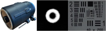
Complementing this, optical metrics tested optical focus and collimation. The USAF-1951 target is used to test focus by evaluating the smallest optical elements discernible. Collimation was checked with a defocused star test (“donut test”), where concentricity of the bright annulus indicates correct primary–secondary mirror alignment. These tests are shown in Figure 6. Any offset or asymmetry suggested tilt or decenter introduced by the mechanism or integration. Metrics were assessed primarily qualitatively in early low-fidelity iterations and increasingly quantitatively as fidelity and resolution increased.
3. Prototype development and key results
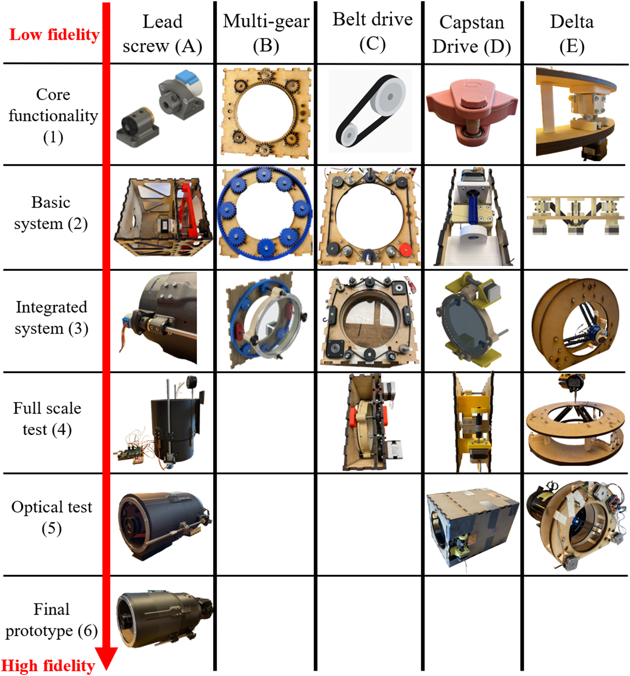
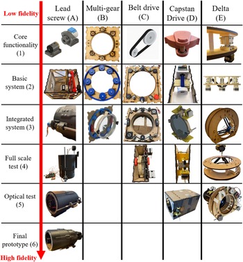
The following section describes the different concepts explored, key insights, and how the prototyping contributed to the final design. Figure 5 summarizes qualitative concept progression with the prototypes while the quantitative comparison criteria and units are reported in Table 1. This figure will be referenced for the rest of this section. Key findings (KF) are followed by an in-depth explanation.
Concept–fidelity matrix. The five concepts are arranged in columns, and successive prototypes with increasing fidelity are shown in rows from top (low) to bottom (high)
3.1 . Exploration of drive architectures (Prototypes 1–3)
The first prototyping phase explored alternative drive architectures for moving the secondary mirror: a corner-mounted lead screw, a redundant gear ring, shared belt drives, a capstan system, and a delta mechanism. All prototypes in this phase were built at low-fidelity (MDF and PLA), with a focus on motion quality, redundancy, and packaging rather than flight performance.
KF1: Single off-axis drive binds easily. The baseline concept (A1–A2) used a stepper motor to drive a lead screw, adjusting focus in an MDF box, with linear bearings guiding a moving plate. In practice, the one-sided drive lacked redundancy, and the side bearings were prone to binding. Relocating the rails towards the mid-edges reduced the lever arm but increased the footprint, showing that the core limitation was guidance stiffness rather than the screw itself.
KF2: Redundant gear rings are heavy and complex. This exploration turned a known unknown into a specified constraint, but did not provide adequate redundancy. A connected gear ring (B1–B3), coupled to multiple stepper motors via MDF spur gears in a single plane, was made. Under load, the MDF teeth broke and exhibited noticeable qualitative backlash, so 3D-printed helical/herringbone gears, along with an external support gear, were introduced. An unknown unknown was the high system friction of the prototypes, which necessitated high prototype resolution. Although this proved that multi-motor redundancy was feasible, an eventual metal implementation would have carried substantial weight, size, backlash, and part count, making the concept unattractive for a small satellite.
KF3: Shared belts are hypersensitive to tension and create single points of failure. Concurrently, a belt-drive system, inspired by commercial 3D printers, was conceptualized (C1) and prototyped with two (C2) and four motors (C3). Despite lower part count and mass than the gear ring, both layouts were highly sensitive to belt tension: over-tension starved the motors, while under-tension produced tooth skip that desynchronized the screws and increased friction. A single shared belt also introduced a new single point of failure. Metal pulleys or larger pitches could have improved the design, but at the cost of added complexity without eliminating the single-belt risk.
KF4: Capstan drives are smooth but still add integration complexity. To explore a simple mechanism with theoretically zero backlash and low part count, a capstan drive concept (D1) was developed and prototyped for familiarization (D2). The mechanism ran smoothly, and a fully integrated system was modelled in CAD with linear support rods (D3). Redundancy could be added by mounting multiple stepper motors on the same axis, but this also increases integration effort and routing complexity.
KF5: Architectural changes beat parameter tuning. Compared to these alternatives, the lead-screw concept remained structurally simpler. A revised version (A3) added two geared stepper motors on a single screw and four radially spaced linear bearings. This preserved the compact corner-actuator packaging while enabling straightforward motor-level redundancy on the same screw. Prototyping across families made it clear that architectural changes, such as switching from a gear ring to a belt or from a belt to a lead screw, had a greater impact than fine-tuning parameters within a weak architecture.
KF6: Delta mechanisms enable collimation, but at a packaging cost. None of the above concepts could adjust collimation because they had only one degree of freedom. A delta mechanism was therefore explored as a potential solution. An in-house delta mechanism using linear bearings and stepper motors (E1) informed a complete CAD prototype (E2), which was subsequently built from the same MDF/PLA materials (E3). These prototypes confirmed that the geometry was feasible, but left questions about footprint, optical obstruction, and in-orbit focusing complexity to be addressed in later tests.
3.2. Backlash evaluation (Prototype 4)
The next step was quantitatively comparing candidate mechanisms for backlash and step size. The capstan, lead-screw, and delta concepts were therefore scaled up to full test size (Prototype 4). The belt drive (C4) did not run smoothly enough to be a credible candidate and was discarded before measurement. Table 1 summarizes the backlash and step size for the remaining three mechanisms.
Backlash and step size performance of candidate mechanisms

The delta mechanism exhibited the least backlash (35 µm), while the lead screw had the smallest step size deviation (0.4 µm). The capstan performed worst on both metrics, surprising the design team and revealing an unknown unknown. KF7: Simple, stiff architectures outperformed intricate mechanisms . Although the delta’s kinematics yielded low backlash, the lead screw offered better controllability and a much simpler structural path, making it a stronger candidate for further refinement.
3.3. Optical integration and packaging trade-offs (Prototype 5)
To understand how the mechanisms interacted with the full optical path, the capstan (D4), lead screw (A4), and delta mechanism (E4) were each integrated into a black box with the telescope optics, yielding prototypes A5, D5, and E5. All three delivered comparable focus and artefact levels; a representative image is shown in Figure 6.
The capstan prototypes (D4–D5) produced adequate optical quality, but the setup was large, exhibited high backlash, required parallel drive to avoid locking, and only adjusted focus, not collimation or secondary-mirror extension. The concept was therefore ruled out. The delta mechanism (E5) matched the unmodified Celestron in optical quality, but in practice, finding the best focus with three coupled degrees of freedom was difficult even in the lab, revealing another unknown unknown. Extrapolated to orbit, this would imply a complex in-orbit focusing procedure with iteration steps on the order of the 90-minute revisit time. Combined with the delta’s larger footprint and slight optical obstruction from its holder arm, this led to the delta concept being discarded.
The linear-rail lead screw (A5) demonstrated equal optical quality, a smaller footprint, and a simpler focusing procedure. Backlash could be further reduced by using a ball screw, and the mechanism could meet the emerging 0.5 µm movement requirement using, e.g., a space-qualified 11:1 integrated gearbox stepper motor from LIN. Taken together, the combination of adequate resolution, low backlash, and simple focus control made A5 the preferred optical performer. At this stage, the platform was shown to support the design goals of fitting within a 20 × 20 cm 16U base, deploying beyond the satellite bus, and achieving high-quality focus and collimation; these were elevated from goals to explicit requirements.
3.4. Final architecture and high-fidelity prototype (Prototype 6)
The final prototype, A6 (Figure 6), consists of a two-part telescope body with inner and outer tubes, both additively manufactured in PA6-CF. The tubes are kinematically linked by four MGN12 linear rails spaced at 90° intervals, while the drive train uses two geared stepper motors, 3D-printed motor couplers, hardened steel lead screws, and two lead-nut brackets, each carrying a pair of lead nuts. At the front, an aluminum lens ring and two retaining rings secure the telescope optics. Focus and collimation tests for A6 are shown in Figure 6.
Final integrated design, defocused star collimation test, and USAF-1951 focus test
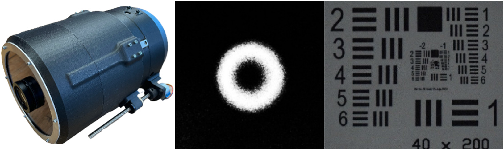
The images taken with A6 confirm that the final architecture delivers stable alignment and reproducible fine focus in a flight-like packaging. In practical terms, A6 combines the optical quality demonstrated in A5 with improved integration and test discipline. Since the work reported here, A6 has successfully passed launch validation, and environmental evaluation is underway. Preliminary tests indicate that adding a third lead screw would further stiffen the system, enabling post-launch collimation adjustments while providing delta-like robustness without the associated complexity.
3.5. Summary of key design insights
From this sequence of prototypes, five key design insights emerged:
-
• Redundancy vs complexity: multi-motor redundancy via gear rings or shared belts quickly increased part count, mass, and single points of failure; a single lead screw was more effective.
-
• Topology before tuning: switching mechanism families (gear ring → belt → lead screw → delta) yielded larger improvements than fine-tuning parameters within a weak architecture.
-
• Simple, stiff architectures are better: despite promising theory, intricate mechanisms (capstan, delta) underperformed the simpler lead-screw rail architecture once backlash, packaging, and controllability were considered.
-
• Optical integration changes decisions: several mechanisms seemed viable as bare rigs but became unattractive when integrated with the full optical path and packaging constraints.
-
• AM is powerful but not neutral: additive manufacturing enabled fast iteration and custom geometries. However, it introduced fragility and process-dependent tolerances, which must be considered when interpreting low-fidelity test results. Prototype materials and fidelity must match the prototype question.
4. Discussion
4.1. Fidelity choices and requirement emergence
In this case study, exploratory low-fidelity prototyping proved effective for achieving a robust design and well-supported decisions. The design team could choose the A1 design and optimize it; however, this would leave a large, unexplored design space. Within this case, analytical generalization indicates that exploratory low-fidelity prototyping enables rapid, flexible design-space exploration with modest time and resource demands, but at the cost of reduced structural robustness and limited flight readiness. The first prototypes used coarse MDF/PLA to quickly discard weak architectures; only once a concept had demonstrated promise were materials, fasteners, and interfaces upgraded. In this sense, fidelity followed insight, not the other way around. Treating fidelity as a risk-management lever lowered the cost of being wrong and enabled architectural pivots (belt → capstan → dual lead screw) instead of over-optimizing dead-end designs. This approach also enables optimizing the topology before fine-tuning the parameters. Large performance jumps came from switching mechanism families rather than from minor parameter tweaks within a weak architecture. This knowledge could be acquired without a high-fidelity test, which would traditionally be the test case. For other NewSpace systems, it is more effective to compare “families” of mechanisms than to prematurely tune a single one. This evaluates mechanisms using system-level metrics and multiple evaluations, not exact numbers. Still, it is important to mention the limitations. Low-fidelity prototypes are not always transferable to the final product, underscoring the importance of the right design choices so that the fidelity of the test matches the question being asked. This research shows that reducing the fidelity of a mechanism intended for space provides valuable insights and effectively locks the design in, with a low probability of redesign. With AM used as a prototyping method, this design could be combined with high-performance polymers, tested, and then flown (Reference Das, Chatham, Fallon, Zawaski, Gilmer, Williams and BortnerDas et al., 2020; Reference Ishfaq, Asad, Mahmood, Abdullah and PruncuIshfaq et al., 2022), necessitating the incorporation of technology readiness level design lifting methods for AM (Reference Borgue, Valjak, Panarotto and IsakssonBorgue et al., 2020).
Reusing a baseline optic mounting plate, telescope interface, and electronics across prototypes reduced redesign overhead and allowed multiple concepts to be compared under similar conditions. This platform approach is broadly applicable to other CubeSat mechanisms and payloads. Balancing ease of assembly and testing with ease of future system integration is important because if a complete system redesign is necessary to integrate the concept into the full payload, the platform on which it is mounted is not ideal. The approach in this study combines exploratory wayfaring with later-stage systems engineering: early exploration, optimization, and design for compliance, followed by launch validation and qualification testing. In incremental testing during requirements definition, one can follow the NASA fly-as-you-test and test-as-you-fly principles (NASA, 1998). Testing as a part of the system is done throughout the development process, making the design more robust. Finding the unknown unknowns through early testing makes redesign cheap. The case shows that wayfaring and rapid prototyping can be used up front to surface the right requirements, which can then be locked down and carried into a more traditional, gated convergence phase. For NewSpace missions, this hybrid model seems more effective than applying a purely linear, requirements-first process from day one.
4.2. Old Space and NewSpace
This case indicates a need for a complementary front end design framework beyond traditional Old Space systems engineering, to structure low-fidelity prototyping and wayfaring in the fuzzy front end. The governance and documentation load of traditional methods can sit uneasily with the need for rapid iteration in NewSpace. The method used in this paper mirrors aspects of concurrent engineering but works on different concepts concurrently to define requirements. Literature is already merging NewSpace practices with Industry 4.0 practices (Eugeni et al., 2022).
The strengths of traditional system engineering models are clearest in the convergence phase. Every requirement has an assigned verification method, configuration control is rigorous, and qualification testing becomes an optimization and proof activity rather than a discovery exercise. Early interface discipline reduces late integration surprises; documentation and review cadence create auditable evidence chains; and environmental campaigns are planned from the outset to demonstrate compliance. Reliability growth is systematic and predictable because failure modes, redundancy policies, and margins are allocated explicitly across subsystems. For large, safety-critical missions with many stakeholders, this governance contains risk and enables certification. New approaches like Model-Based System Engineering are effective methods for this (ESA, 2023).
This paper, therefore, treats the traditional approach as essential for back-end traceability, qualification, and documentation, while acknowledging its limitations at the front end. Because requirements are traditionally frozen early to enable decomposition and contracting, physical learning tends to occur after detailed design, when changes are expensive. Old Space limits can slow iteration when uncertainty is highest; unknowns are often covered by conservative margins, which drives mass, volume, and cost upward and can bias teams toward heritage solutions. When key performance drivers are poorly understood, such as achievable focus resolution or packaging size of alternative topologies, integration risk can be a concern. A defining feature of the development process in this paper is the transfer of knowledge across concepts. Assembly tricks, fixture ideas, and sub-mechanisms that prove effective in one concept are migrated sideways into others, allowing the surviving path to accumulate validated sub-solutions without re-discovering them. Fidelity is raised only as evidence accrues, meaning fasteners, materials, and interfaces are upgraded when they remove known limitations rather than in anticipation of hypothetical ones. Crucially, when tests revealed shortfalls, this paper preferred principled architectural changes (e.g., switching drive topology or kinematic structure) over local parameter tuning, avoiding over-optimization of dead ends.
The output of each cycle is not a finished design but a clearer, smaller set of validated requirements. Observed large focus steps translate into a quantitative step size requirement; measured slip or hysteresis becomes a low-backlash or closed-loop requirement; and packaging size becomes a bus requirement. Only after these needs were evidenced did this paper converge the lanes and commit to a higher-fidelity, flight-like mechanism. In this way, the process systematically transforms early ambiguity into a design space bounded by facts rather than forecasts. Using lower-fidelity prototypes could complement traditional Stage-gate systems to inform early design gate decisions.
It is a particularly dynamic time to explore the design space in the NewSpace era. Lower costs and shorter development cycles are enabling new missions and technology to fly in space. “The increasing specialization of New Space studies opens up opportunities for complex space missions, including debris removal, satellite repair and refueling, and autonomous operations.” (Reference Ferrara, Cicconi, Minotti, Trovato and CaputoFerrara et al., 2025). It is therefore important to build design knowledge around effective, practical design methods in the new paradigm. Companies such as SpaceX conduct many flight and ground tests, losing vehicles in the process, to accelerate learning, echoing the early Apollo era but contrasting the risk-averse Old Space paradigm.
5. Conclusion
This paper shows that low-fidelity wayfaring can be an effective strategy for clearing the fuzzy front end of NewSpace hardware projects. By using process tracing across 23 low-fidelity prototypes for a CubeSat telescope focus mechanism, this study provides evidence of how deliberate fidelity management can support the emergence, refinement, and validation of requirements for complex space mechanisms. The main contribution is to link concrete fidelity choices to specific learning outcomes: coarse prototypes to eliminate weak architectures and surface unknowns; intermediate prototypes to quantify critical metrics such as backlash and step size; and higher-fidelity prototypes to verify integration and optical performance. This moves rapid prototyping from a generic “enabler” in NewSpace to a structured, empirically grounded design approach. For practitioners, the case suggests that NewSpace teams can front-load learning by accepting many cheap, low-fidelity builds, especially when dealing with COTS-based payloads and co-evolving bus constraints. Rather than replacing traditional NASA/ECSS systems engineering, this approach complements it, as wayfaring is used to discover the right requirements, which can then be carried into a conventional verification and qualification flow. Future work should test this fidelity-aware wayfaring pattern across other mechanisms and missions to assess how widely it generalizes across the NewSpace domain.


 Open access

