

I. INTRODUCTION
The analysis of studies of approximately 400 000 high school students over five decades (Wai et al., Reference Wai, Lubinski and Benbow2009) showed that success in the Science, Technology, Engineering and Mathematics (STEM) domains is directly linked to a person's skill in visualizing spatial relations in two and three dimensions. The most direct form of three-dimensional (3D) visualization involves touching and manipulating objects directly with one's hands (Figure 1).
(Color online) 3D print of the caffeine molecule model [by the Color Jet Printing (CJP®) process].

With 3D printing (Berman, Reference Berman2012) entering the worlds of science (Jones, Reference Jones2012) and mainstream bio-chemistry/chemistry/crystallography (Herman et al., Reference Herman, Morris, Colton, Batiza, Patrick, Franzen and Goodsell2006; Olson et al., Reference Olson, Hu and Keinan2007; Chakraborty and Zuckermann, Reference Chakraborty and Zuckermann2013; Chen et al., Reference Chen, Lee, Flood and Miljanić2014; Halford, Reference Halford2014; Kitson et al., Reference Kitson, Macdonell, Tsuda, Zang, Long and Cronin2014; Moeck et al., Reference Moeck, Kaminsky and Snyder2014a, Reference Moeck, Stone-Sundberg, Snyder and Kaminskyb; Scalfani and Vaid, Reference Scalfani and Vaid2014), user-designed physical models for both education and research can potentially be produced cost-effectively. Here we report briefly on ongoing software developments to create 3D printed crystallographic models seamlessly from the structure report files created with X-ray, neutron, or electron radiation experiments on crystals of small molecules and proteins as well as on inorganic crystals (that do not consist of individual molecules). These reports are standardized in the Crystallographic Information Framework (CIF) format (see THE format details here: http://www.iucr.org/resources/cif/dictionaries, file extension *.cif) and available online from multiple databases. There are already several pathways to create 3D printed models from CIF files via existing software (Herman et al., Reference Herman, Morris, Colton, Batiza, Patrick, Franzen and Goodsell2006; Chen et al., Reference Chen, Lee, Flood and Miljanić2014; Kitson et al., Reference Kitson, Macdonell, Tsuda, Zang, Long and Cronin2014; Scalfani and Vaid, Reference Scalfani and Vaid2014; to quote only what is published in peer reviewed papers). These pathways typically involve transitions between different software packages and associated file formats. [A typical pathway may include: create a *.pdb file (the original file format of the worldwide Protein Databank (Berman et al., Reference Berman, Henrick, Nakamura and Markley2007) from a *.cif file with ORTEP3, http://www.iucr.org/resources/other-directories/software/ortep-3-for-windows or other software packages, import the *.pdb file into Meshlab, http://meshlab.sourceforge.net/, export as *.stl, import that *.stl file into Netfabb (a commercial package) http://www.netfabb.com/ to correct errors, and finally send the corrected *.stl file to the 3D printer.]
We aim at providing a straightforward pathway, which is reduced to loading the structure's *.cif file into a single Windows application, Cif2VRML, followed by saving the 3D printable file involving only one mouse “click”. The reason for our choice for selecting the Microsoft platform is based on the following:
-
(a) The 3D printer software, connected to the 3D Printers, predominantly utilize Microsoft Windows (CubeX, http://www.3dsystems.com/3d-printers/personal/cubex) and supporting software, MAGICS: http://software.materialise.com/, Solidview: http://www.solidview.com/);
-
(b) 91 % Microsoft market share of operating systems on Laptop/Desktop computers [source (2014): http://www.netmarketshare.com/operating-system-marketshare.aspx?qprid=8&qpcustomd=0]. These machines are the most likely to be used accessing *.cif data and preparing 3D print files;
-
(c) The program is written by one of us (W.K.) in the DELPHI language, which is available only on Windows;
-
(d) Cif2VRML requires the CORTONA VRML viewer (http://www.parallelgraphics.com/products/cortona3d/), which is incorporated into the software to enable high-quality and real-time motion presentation of structures on the screen. This browser add-on is also freely available, but only for Windows-based executables;
-
(e) If ported to a mobile device, additional steps are likely required to move *.wrl or *.stl data (the preferred two 3D print file formats) to a printer (e.g., emailing a computer or connecting a device to a computer).
There are multiple software choices to load CIF data and view them interactively on a computer screen; see Hanson (Reference Hanson2010) for a brief review. The finest of these programs, Jmol (Hanson, Reference Hanson2010, http://wiki.jmol.org/index.php/Main_Page), is free of charge and very popular because fully functioning applets can be integrated into web pages. The Jmol program allows for exports to *.wrl and *.obj formats, suitable for 3D color printing and there are plans to expand its functionality to include *.stl file exports. Jmol applets with these export functions will be ideal for inclusions into the websites of Internet based crystallographic and protein molecule databases (e.g., http://crystallography.net, Gražulis et al. Reference Gražulis, Chateigner, Downs, Yokochi, Quirós, Lutterotti, Manakova, Butkus, Moeck and Le Bail2009, Reference Gražulis, Daškevič, Merkys, Chateigner, Lutterotti, Quirós, Serebryanaya, Moeck, Downs and Le Bail2012; http://proteopedia.org/, Prilusky et al., Reference Prilusky, Hodis, Canner, Decatur, Oberholser, Martz, Berchanski, Harel and Sussman2011). Note that with the beta version of the Crystal Data Repository of the Royal Society of Chemistry (RSC, http://api.beta.rsc-us.org/Crystals/v1/cod/), a crystallographic database exists that features currently tens of thousands of downloadable *.stl and *.wrl files of small molecules and crystalline solids. (There are plans to host hundreds of thousands of freely downloadable 3D print files at this RSC database.)
A related task is the creation of 3D printed models of crystal morphologies. These can be created with WinXMorph (Kaminsky, Reference Kaminsky2005, Reference Kaminsky2007), which is able to read morphology data (if included) from *.cif files. An example of a 3D printed crystal model from a print file created with that software is shown in Figure 2. Both programs can be downloaded from the Internet for free: http://cad4.cpac.washington.edu/WinXMorphhome/WinXMorph.htm and http://cad4.cpac.washington.edu/Cif2VRMLHome/Cif2VRML.htm. The software presented here will only require a license from the University of Washington at Seattle if commercial usage is intended.
(Color online) Left: Screen-shot of a sugar (sucrose) morphology model with green lines representing the facet normal. Right: 3D printed model in nylon by the Selective Laser Sintering™ (SLS®) technique, where the STL file was created from data in a CIF file with the WinXMorph software (Kaminsky, Reference Kaminsky2005, Reference Kaminsky2007). This model has dimensions of a few centimeters.

In this report, we discuss requirements for color and monochrome 3D printing and how they are being met by Cif2VRML. Also we discuss the challenges of different CIF “dialects”. Finally, recommendations for 3D printing of crystallographic models are made based on the insights of a technical expert from industry (T. S.). An outlook on new print materials under development complements that section.
II. REQUIREMENTS FOR 3D PRINTING AND CIF2VRML SOFTWARE OPTIONS
The most obvious requirement for 3D printing is that the object to be printed does not consist of disconnected subsets; yet, crystals can contain ions or several individual moieties that need to have some physical connection to facilitate printing. However, one cannot just arbitrarily create connections between atoms, as this may be misunderstood as indicating a fictional chemical bond. It is therefore necessary to add to normal atomic bonds additional reasonable van der Waals (vdW) or hydrogen bond interactions, as those will serve in the model, as they do in the real crystal: holding it all together.
It is in the interest of any crystallographer to prepare her or his data, so that all parts of the structure are in close vicinity to represent the actual bond interactions. It may, however, be necessary to check the atom coordinates for possible shorter, symmetry-driven placements of otherwise disconnected moieties. Detecting and treating ionic interactions programmatically provides in this context the largest challenge, which may cause a 3D-printed structure to be separated into those charged moieties. While calculating all possible bonding interactions, the software could sort atoms into groups of connected entities and inform the user of any such problems.
A. H-Bond and vdW bond constraints
Bonds are typically visualized by rather thin cylinders, which creates another challenge as it introduces model instabilities if too thin and conversely esthetic problems if too broad. Possible vdW bonds involving hydrogen require calculating the distance between hydrogen and acceptor atoms (aa), as well as the donor-H-acceptor angle.
Donor atoms (da) include elements C, N, O, F, S; aa include: N, O, F, S, Cl, Br, I, where for N, F, and S the covalent radii are used for the distance search instead of the vdW radii. Carbon is not a da in a strict sense, but is included just the same. The maximum hydrogen-to-acceptor distance has to be within 0.5 Å of the sum of vdW radii of H and aa. The minimum allowed is the named sum – 1 Å, and the angle da-H-aa to be within 100°–180°. True hydrogen bonds are distinguished by excluding carbon as a da. The empirically found best suitable radius of oxygen, which may exhibit lone electron pairs, for establishing vdW bonds is 0.8 Å.
B. Further program options beyond a one-click process
Ideally, and in many cases for simple molecules such as caffeine (Figure 1), the software represents the model ready for printing. Many users, however, will appreciate a range of software choices.
The model size is preset to 10 cm across the largest extension, which a user may want to change to other values between 2.5 and 25 cm. This choice directly impacts printing costs.
-
(a) Disordered moieties, often distinguished by different “Part” numbers, can be selected or deselected.
-
(b) One may not want hydrogen atoms to be present.
-
(c) One may want to limit the model to true hydrogen bonds, excluding carbon as da, or with no vdW interactions at all.
-
(d) For protein structures, water molecules are by default suppressed, but can be re-selected.
-
(e) One may want to deselect the backbone rendering of amino acids and show them as individual atoms.
-
(f) Backbone rendering requires some additional non-bond representing bridges. The default “catch” radius can be changed to reduce or increase the occurrence of such stabilizing additions to the model.
-
(g) Symmetry extension of single molecules may be desired in order to represent whole crystal structures (to be implemented in a software upgrade in the near future).
-
(h) A more open molecule model may represent atoms at half their covalent radii, however, that could reduce the model's stability. One may then want to change to atoms printed with covalent radii. Highest stability is achieved by using the vdW radius to render atoms.
We believe that software options are important because the most effective models (Charbonneau, Reference Charbonneau2013) will enrich more traditional education and research tools. The goal of further developments should be: rather than to replace other representation forms, 3D printed models should complement them. In the words of one of a pioneer in 3D printing of inorganic cluster molecules (Leroy Cronin): “I don't want chemistry reduced to plastic trinkets, I want new science to occur as a result of use of ubiquitous 3-D printing and molecular design.” (Halford, Reference Halford2014).
III. COLOR AND MONOCHROME PRINTING
True-color 3D printing requires a different file standard than monochrome printing. The current file format for monochrome printing is guided by the Standard Tessellation Language (STL), file extension *.stl. This format was developed for monochrome printing and even the most inexpensive 3D printers can interpret it. If a 3D printer has multiple print heads, then each may be loaded with a differently colored polymer, and different *.stl files containing selective objects can be assigned to those print heads. The surface of an object has to be triangulated, and each triangle is represented by vectors (vertices) to its corners and a face normal vector indicating the directions to the model outside:
solid modelname STL
facet normal −0.755 −0.656 0.000
outer loop
vertex −12.11 −3.60 7.25
vertex −4.26 −12.63 0.98
vertex −7.38 −9.04 6.17
endloop
endfacet
…
endsolid modelname STL
A model can be printed in color from a *.wrl file (say “vormel file”). Here is a syntax example (from the caffeine molecule model in Figure 1):
#VRML V2.0 utf8
# styles
Transform {children [Shape {appearance DEF C Appearance {
material Material {diffuseColor 0.45 0.45 0.45
ambientIntensity 0.2 specularColor 0.1 0.1 0.1 shininess 0.1}}}]}
…
# Atoms
Transform {translation 0 −19.37 −10.67
children [Shape {appearance USE C geometry Sphere { radius 4.92000 }}]}
…
# bond style
Transform {children [Shape {appearance DEF bondstyle Appearance {
material Material {diffuseColor 0.7 0.7 0.7
ambientIntensity 0.2 specularColor 0.1 0.1 0.1 shininess 0.1}}}]}
Transform {translation 0.01 −1.19 −23.41
rotation 1 0 −0.001 1.797
scale 12.77 15.56 12.77
children [Shape {appearance USE bondstyle
geometry Cylinder { height 1 radius 0.13 }}]}
…
Note that this file format is not accepted by all VRML capable 3D print software packages, where some may require spheres and cylinders to be represented explicitly by adding the coordinates and connecting polygon data to the *.wrl file, similar to what is required for the *.stl file format. (See also: VRML standard descriptionhttp://xml.coverpages.org/vrml-X3D.html.)
Surface differences are implemented in Cif2VRML to provide tactile feedback for the difference between model atoms, as shown in Figure 3. We believe this feature will aid in the utility of 3D models to visually impaired people (Wedler et al., Reference Wedler, Cohen, Davis, Harrison, Siebert, Willenbring, Hamann, Shaw and Tantillo2012).
Rendering of 3D printed elements. (A) quasi-smooth sphere for carbon, hydrogen, and many other atoms. (B) Non-sphere representation of nitrogen, (C) non-sphere representation of oxygen.
The polygonal models in Figure 3(B) and (C) were designed and saved as *.stl files with WinXMorph (see, Figure 2) and a highly resolved STL cylinder of unit dimensions was created this way as well. While spheres representing atoms are simply scaled to the desired radius and then shifted from the origin to the atomic coordinates added to the reference sphere vertices, a cylinder for representing a bond requires calculation of an “axion” rotation vector (see the Appendix).
IV. CIF – DIALECTS
Not all *.cif files were created equally. There are differences between current versions and those saved before 1997; differences between small-molecule CIFs and protein CIFs and within those, atomic coordinates may be listed differently (Table I). A single CIF file may contain multiple structures, following a requirement for manuscript submission to several scientific journals. As a result, the Cif2VRML software attempts to be flexible enough to recognize the different “dialects”, load the data properly, and make a model that can be printed directly.
CIF-entry lines to load the x-coordinate of an atom _
V. EXAMPLES AND MODEL IMPROVEMENTS
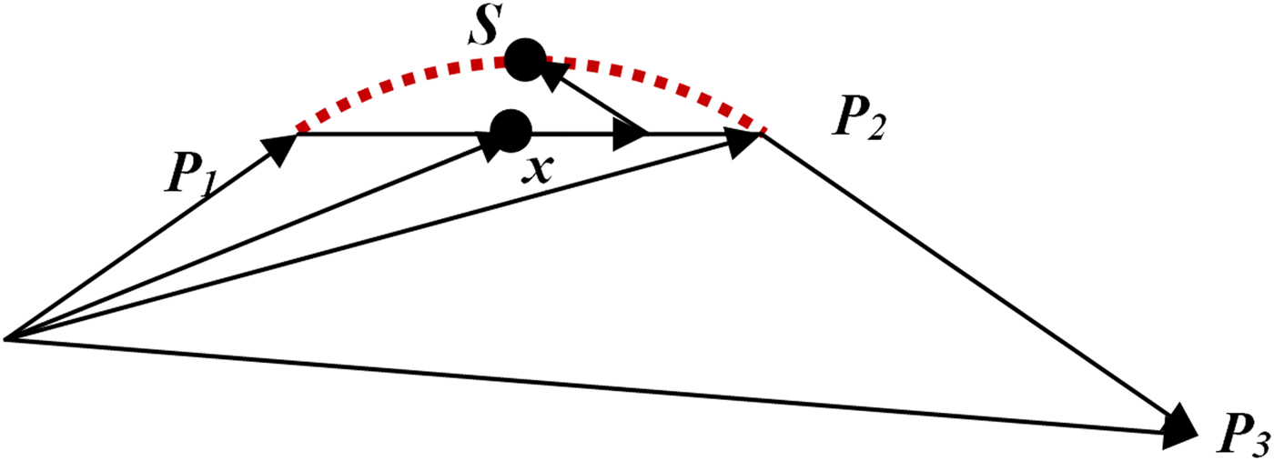
Below we give examples of screenshots and actual printed monochrome molecule models of caffeine and a chlorophyll protein. The amino acid sequence in that protein is rendered as “backbone”. Here, the geometrical averages of atom coordinates for each amino acid are connected in the order of the protein sequence with a “metallic blue” colored cord. A simple spline operation, adding one additional coordinate S in-between two amino acid centers P 1 and P 2, creates a smooth helical appearance (Scheme 1). Point x = ½( P 1 + P 2), S = x + r·( P 2 − P 3), and r is the spline parameter; r = 0 means no spline in which case S coincides with x . With r = 0.25 and repeating the algorithm with P 2 as a new starting point and so forth until the end of the sequence is reached, we found helices to be most intuitive.
(Color online) A very simple 3D-spline algorithm. Adding to point x the vector y = P 2 − P 3, scaled by spline parameter r leads to spline point S . One may also add an additional, small shift z = P 2 − P 1, scaled by the projection of r· y onto z , as shown. However, the improvement is small because the angle P 1 − P 2 − P 3 is around 90° for most helices.
Non-amino acid atoms are represented at their vdW radii. Additional small bridges are included where parts of the backbone come close within a specified distance to enhance model stability. These hardly recognizable connections are not actual bonds, but one could imagine that most of the times they go along amino acid interactions. To prevent bridges within a backbone, only every 15th amino acid is allowed to make one. The catch radius is set to about 4.25, and 0.75 Å more to establish a bridge between an amino acid and any non-sequence atom.
VI. MATERIALS RECOMMENDATIONS AND OUTLOOK
With multiple 3D manufacturing methods and material choices available, one should expect a wide variety of output forms and print methods involving different build physics. The specific additive manufacturing method as part of the design, model creation, and end use requirements have to be weighed against the needs (i.e., fidelity, color, toughness, cost, and availability). The numerous printing and materials technologies available include many different plastics such as acrylonitrile butadiene styrene (ABS), polylactic acid (PLA), nylon, ultraviolet light curable polymers, wax/resins, proprietary powders, numerous metals, and others classes of materials.
Of particular interest for the hobbyist are the numerous “home-made” extrusion deposition-type printers, which can be built or purchased for a few hundred to a few thousand dollars. Owing to the simplicity of the mechanical design and material availability these printers are very popular with the do-it-yourself community, also known as the “makers.” Home-made devices such as RepRap printers (http://reprap.org; Wittbrodt et al., Reference Wittbrodt, Glover, Laureto, Anzalone, Oppliger, Irwin and Pearce2013) can be used to make models from *.stl files in materials such as ABS, PLA, nylon, and high-density polyethylene. These kinds of devices utilize open-source hardware (Bowyer, Reference Bowyer2014) and are able to partially replicate themselves by printing many of their own parts. These 3D printers typically utilize only a single material and must use that material for both the model building and the support structures. Inherently, this results in limitations of a model's complexity and print quality. Owing to the reduced spatial resolution of these kinds of inexpensive printers, it is recommended to print at larger sizes to preserve surface characteristics as shown in Figure 3. (There are already too many hobbyist designs of 3D printers to list here.)
The 3D print files can be sent out to professional online print services (http://www.3dsystems.com/quickparts, http://www.sculpteo.com/en/, or http://www.shapeways.com/), when specific material choices and higher quality print outs are desired. For example, detailed museum-quality models with spatial print resolution down to 16 µm and striking fidelity can be made via the Multijet™ printing (MJP®) process, as used for the chlorophyll molecule model, shown in Figure 4(D). When printed with a clear material (such as the VisiJet Crystal material), the resulting models are translucent and have glass-like properties. Similar monochrome models can also be made in opaque colors such as white, navy, gray, and black.
(Color online) Top row: Screen renderings of molecules (A) caffeine and (B) chlorophyll. Bottom row: 3D printed models of (C) caffeine (fused deposition plastic) and (D) chlorophyll [Multijet™ printing (MJP®) process, printed on a 3D Systems Projet 3500 printer, material: VisiJet by 3D Systems Corporation]. Although the caffeine model in (C) is about 15 cm wide, the protein model in (D) has dimensions of a few centimeters. (A colored model of the caffeine molecule from colored and cemented gypsum powder is shown in Figure 1.)

Two color printers such as the 3D Systems' Cube and Cube Pro and Makerbot Replicator 2x have recently become available. These printers can be used to make single color models from a single standard *.stl file. Dual-color capability is enabled with the use of two interlocking *.stl files, or proprietary software that ships with the machines. These kinds of machines typically only print in ABS and PLA materials (although other material can be made to work by the hobbyist). Dual-color extrusion printers are rather inexpensive, but the accuracy and fidelity of the 3D printed models and their ability to reproduce many complex shapes are more limited compared with other technologies (at least for now).
Crystallographic models of molecules and solids with a range of different atoms require multiple colors and sufficient durability for the best end-use experience. The new Projet 4500 Multijet™ printer of 3D Systems Corporation is currently the only printer that produces 3D multiple color prints in durable VisiJet® C4 Spectrum plastics.
The other contemporary multiple color printers use the so-called “Z Corp” technology [currently known as ColorJet Printing® (CJP) from 3D Systems Corporation] and its derivatives. This method uses inkjet technology to deposit a liquid binder across a bed of powder. The powder is released and spread with a roller to form each new layer and result in print-outs consisting of colored gypsum (Figure 1) or sandstone-based plaster that were dipped into superglue to harden their surface and enhance their stability.
New processes and materials with strong stretch, bend, and twist tolerances, are being developed and introduced at regular intervals. Recently released new materials include the VisiJet CF-BX, which offers 300% elongation before breaking. It is expected that the products offered in the future from all manufactures will continue to enable extremely durable 3D color printed objects suitable for a wide variety of education and research applications.
VII. SOFTWARE IMPROVEMENTS
The Cif2VRML software is presented as a development in progress, with features being added over time. The scope though shall remain limited; keeping in mind that Cif2VRML is intended to quickly produce printable models and to remain usable by non-experts. However, we are open to suggestions by our users, who already requested adding import options from other file formats and providing a console version without graphical interface in order to enable batch processing.
Appendix
The steps used in Cif2VRML to create *.wrl and *.stl files follow the standard procedures, referenced here for those unfamiliar with this matter. Given two atoms at positions p 1 and p 2, and a cylinder along y = (0, 1 0) of length 1 and desired radius relative to unity, and then the cylinder translation t = ½(p 1 + p 2), represents the center between the bonded atoms. With bond vector s = p 2 – p 1, the first three co-ordinates of a rotation axion r are calculated from r = (s × y)/|s × y|; the fourth coordinate in radian, rotation angle r α , is calculated via arccos(y·s/|y||s|).
The new length of the cylinder is defined by scale |s|, the overall model scale is s m. The results are included in the *.wrl file syntax via: translation t rotation r r α scale sm sm|s| sm, with scale applied first, then rotation, followed by the translation.
The vertices of the reference spheres and cylinders for a *.stl file are similarly scaled and translated, but cylinder vertices are rotated by 3 × 3 matrices to be generated from the axions.
Let the matrix coordinates = m[i,j], axion = r[k], i,j: 0 .. 2; k: 0 .. 3. The following calculations create the rotation matrix m.
c: = cos(r[3]);w: = sin(r[3]);t: = 1 − c;
x: = r[0];y: = r[1];z: = r[2];
wx: = w•x;wy: = w•y;wz: = w•z;
xx: = x•x;xy: = x•y;xz: = x•z;
yy: = y•y;yz: = y•z;zz: = z•z;
m[0,0]: = t•xx + c; m[0,1]: = t•xy − wz; m[0,2]: = t•xz + wy;
m[1,0]: = t•xy + wz; m[1,1]: = t•yy + c; m[1,2]: = t•yz − wx;
m[2,0]: = t•xz − wy; m[2,1]: = t•yz + wx; m[2,2]: = t•zz + c;
ACKNOWLEDGEMENT
The US National Committee for Crystallography (http://sites.nationalacademies.org/pga/biso/IUCr/) supported the development of both the Cif2VRML program and the export *.stl function of the WinXMorph program.


