


Background
The Laboratory of Electromagnetic Theory (now Department of Electromagnetic Systems), Technical University of Denmark (DTU), started working with ice sounding in the mid-1960s. A few preliminary tests were carried out in spring 1968, and a small flexible 60 MHz radar for ice sounding was designed, built and tested in 1969 (Reference Christensen and GudmandsenChristensen, 1970; Reference Christensen, Gundestrup, Nilsson and GudmandsenChristensen and others, 1970; Reference Gudmandsen and WaitGudmandsen, 1971; Reference GoodmanGoodman, 1975). The radar was later flown on a U.S. Navy C-130 in Greenland. An improved and fully operational second-generation system was used by DTU and the Scott Polar Research Institute (SPRI), Cambridge, U.K., for mapping of the ice sheets of Greenland and Antarctica on aircraft operated by the U.S. Navy (Reference Gudmandsen, Nilsson, Pallisgaard, Skou and SondergaardGudmandsen and others, 1975; Reference Skou and PedersenSkou and Pedersen, 1976). The original 60 MHz radar has been used occasionally in connection with ice-core drilling projects in Greenland (Reference Overgaard, Gundestrup, Langway, Oeschger and DansgaardOvergaard and Gundestrup, 1985).
Several airborne ice-radar systems, including updated ones, exist and are operated by various research organizations. A comprehensive list is included in Reference Gogineni, Chuah, Allen, Jezek and MooreGogineni and others (1998) which also provides a survey of the development of ice-thickness sounding and a comprehensive bibliography of historical and recently published material. The technique of ice radar has developed from simple incoherent pulseradar systems with analogue data recording to modern radar systems exploiting coherent techniques (e.g. synthetic aperture), pulse compression, digital signal processing, etc. Under certain measurement conditions, however, the simple pulse radar can still produce satisfactory results.
The recent interest in the mass balance of the major ice sheets has led to intensified research regarding Greenland glaciers (e.g. Reference Thomsen, Olesen, Starzer, Boggild and ReehThomsen and others, 1997; Reference Reeh and MadsenReeh and Madsen, 1998; Reference AbdalatiAbdalati, 1999). Scanning laser altimeters have been used to map the surface of ice sheets and glaciers (Reference EchelmeyerEchelmeyer and others, 1996; Reference Favey, Geiger, Gudmundsson and WehrFavey and others, 1999; Reference KrabillKrabill and others, 1999). Satellite-based synthetic-aperture radar (SAR) systems have offered the technology to map wide areas with good accuracy, and projects for mapping the large ice sheets are in progress (S. N. Madsen and others, http://www.esa.int/fringe99). Space-borne SAR interferometry, especially using the tandem mode of the European Space Agency’s ERS-1/2 satellites, has enabled simultaneous mapping of the three dimensions and the surface velocity of glaciers (Reference Nielsen, Forsberg, Ekholm and MohrNielsen and others, 1997; Reference Mohr, Reeh and MadsenMohr and others, 1998). However, measurements of ice thickness, required by several methods for assessing the mass balance of ice sheets (Reference RignotRignot, 1996; Reference ReehReeh, 1999; Reference Reeh, Madsen and MohrReeh and others, 1999), are presently not available from satellite-based systems.
This is the general motivation for reviving the old ice radar from 1969 and integrating it with modern data acquisition, navigation and altimeter equipment. A specific motivation was the need for accurate glacier surface and ice-thickness maps in connection with the Nioghalvfjerdsfjorden glacier project presented in the final section of this paper as an illustration of the system’s performance.
Aircraft
The small Twin Otter aircraft was used for the system, mainly for logistic and economic reasons. The size of the aircraft limits the antenna to a dipole, which results in a wide radiation pattern (making the radar sensitive to surface echoes) and a narrow bandwidth, but in return the Twin Otter construction enables a very low-cost ice-radar installation to be made without any changes to the aircraft. This aircraft has the additional advantages that it can navigate very close to the ice surface in spite of the mountains at the edges and that it can land on the natural landing strips in the area. Greenlandair has two of these aircraft already in use for logistics and research flights for various applications in Greenland.
In order to fulfil the mission requirements, the aircraft also has to carry a laser altimeter and a kinematic global positioning system (GPS) with data-recording equipment. The Danish National Survey and Cadastre has this equipment available for easy installation on the Twin Otters as part of the hardware set-up for a new small-plane aerogravity operation over the continental-shelf regions around Greenland (Reference Forsberg, Olesen and KellerForsberg and others, 1999). A GPS reference station was established for the duration of the mission at a landing strip next to the glacier, with a back-up reference at station Nord.
Kinematic GPS and Laser-Altimeter Equipment
The equipment for the aircraft navigation is based on differential GPS receivers, augmented with a low-cost custom-made inertial measurement unit (IMU) and a laser altimeter. The equipment is designed for aerogravity applications, which demand high absolute and relative positioning accuracy (at the dm-level), especially in the vertical direction.
An Optech 401 SX infrared pulsed laser altimeter is used to measure the aircraft-ice-surface distance. The laser is operated at a 50 Hz sampling rate, and the data are logged along with IMU data. The accuracy of 1 s averaged laser ranges is typically at the 10–20 cm level, depending on the roughness of the surface. Over the ocean the laser may exhibit a relative (filtered) accuracy of < 10 cm (Reference Forsberg, Hehl, Bastos, Gidskehaug and MeyerForsberg and others, 1996).
Kinematic aircraft GPS solutions are computed using two Trimble 4000 SSI receivers, operating on separate antennas mounted on the aircraft. Reference GPS stations were located both relatively close to the operations area and at the airstrip of the mission base. GPS solutions are based on commercial software (“GPSurvey”), with reference coordinates tied into the global reference system (ITRF96) through ties to the IGS global GPS tracking network. Two GPS units were used to provide a redundancy in the accurate measurement of the aircraft elevations, with a goal of this position being at the 20–30 cm level. By combining the position information with the laser range measurement, the ice surface is positioned absolutely in height at the same level of accuracy.
The custom-made strapdown IMU consists of three Litef fibre-optics gyros and three Schaewitz accelerometers developed by Greenwood Engineering, Brøndby. The IMU is primarily used to give attitude angles, used for pointing the laser altimeter and for correcting the lever arms of the GPS antennas to compensate for aircraft roll, pitch and yaw. The IMU is also useful for a quality check of problems in the GPS solutions (e.g. cycle slips). When it is combined with GPS, roll-and-pitch accuracy of around 0.1–0.2° is typically obtained. The overall navigation system thus allows high-precision mapping of the ice-surface heights along a narrow profile immediately below the aircraft, and also provides an absolute height reference for the ice radar.
Reasons for Using the Old Radar
The old 60 MHz radar from 1969 (Reference Christensen, Gundestrup, Nilsson and GudmandsenChristensen and others, 1970) was available, and due to its low weight and power consumption (8 A from the aircraft unregulated 28 V d.c. power) it was an obvious choice for an ice-sounder system based on the small Twin Otter.
Some deficiencies of the old radar system are difficult to remedy. The receiver would have to be completely redesigned to achieve coherent operation and thus the benefits of coherent processing, i.e. high spatial resolution in the flight direction and the consequential suppression of surface echoes. Furthermore, the low frequency of operation would require a large and expensive antenna installation (and thus a large aircraft) to achieve a high bandwidth, which is needed for a good resolution in the thickness measurements, and a high directivity, which helps to produce a small and well-defined measurement area. However, the radar also offers benefits.
The data acquisition took place in the summer, when the top of the glacier is melting, i.e. a lot of meltwater pools are scattered over the surface, and the snow on the ice is wet. In order to penetrate the wet surface, a low operational frequency is preferred, i.e. around 60 MHz since lower frequencies would be disturbed by shortwave broadcast. Most modern airborne systems use higher frequencies (Reference Gogineni, Chuah, Allen, Jezek and MooreGogineni and others, 1998), e.g. 150 MHz; the authors do not know whether these would work equally well on the wet glacier.
The glacier has large areas with a very rough surface and small-to-medium ice thickness. Under these conditions it is important to use a system with a narrow pulse exhibiting a short decay time, and the lack of a pulse compression system is not a drawback since that would exhibit range side lobes extending over twice the duration of the uncompressed pulse.
Antenna Construction
The Twin Otter has a horizontal open-ended tube crossing the fuselage as part of the structure of the aircraft between the luggage department and the tail (intended as a lifting point). This tube makes it easy to install a large dipole. However, the design of an antenna for such an installation with a reasonable bandwidth is not a trivial matter since the tube is welded to the fuselage and both items are conductive (aluminium). It is not possible to cut a hole in the tube for the antenna cable if a major certification procedure is to be avoided, and the same holds for installing any parts beneath the fuselage at that location since it comes quite close to the runway during take-off and landing. The design is illustrated in Figure 1.
Schematic of the 60 MHz dipole. The arrow on the inserted schematic of a Twin Otter shows the location of the tube used for antenna mounting

The dipole consists of two aluminium tubes connected by a dielectric (isolating) tube which fits tightly within the tube in the aircraft fuselage. The antenna is connected to the radar by a coaxial cable running inside the antenna tube and a balancing transformer (balun) at the dipole centre gap. The coaxial cable runs along the aircraft fuselage, fixed by tape, to a point where it can be connected to the interior of the aircraft. One of the Twin Otters has a feed-through connector in the fuselage, while the other has sufficient space beneath one of the doors to allow the cable to pass through. The coaxial cable is led through a ferrite core at the exit from the antenna tube in order to prevent the antenna current from leaking along the transmission line formed by the outer conductor of the cable and the fuselage.
A removable dielectric ring on each side of the aircraft keeps the dipole in position. Installation is performed by simply removing one ring, pushing the antenna through the tube and reaffixing the ring to the antenna. After that, the cable is fixed by tape and guided inside the aircraft to the location of the sounder. The aircraft has not been modified, and when everything has been fitted the whole operation takes about 15 min.
The antenna return loss is −14 dB measured under airborne operational conditions by applying the actual transmitted pulsed signal (i.e. a wider bandwidth than utilized by the complete system) to the antenna through a directional coupler.
The Basic Radar System
An overview of the radar system is displayed in Figure 2, and the parameters are summarized in Table 1. The transmitter is a crystal-controlled oscillator followed by a pulse modulator, a sequence of class C transistor amplifiers and a vacuum-tube power amplifier. The power amplifier utilizes quadrature hybrid couplers to assure good impedance matching towards the antenna in order to minimize multiple reflections on the antenna cable. The pulse repetition frequency (PRF) is user-selectable up to 32 kHz, and the pulse width is likewise user-selectable in the range 60–1000 ns.
Ice-sounding radar system overview. The radar and the laser-altimeter record data independently, however, synchronized by GPS time.

Summary of parameters for the original and the present version of the radar and the settings actually applied for data acquisition with Twin Otter (velocity 70 ms−1)

Two modifications have been introduced since the original construction, namely, a new high-tension power supply for the tube power amplifier (improving the reliability but also lowering the peak output power to P t = 600 W for 250 ns pulses at a PRF of up to 13 kHz) and circuitry for external triggering of the transmitter pulse. Furthermore, an outdated module for analogue synchronization of the radar data with navigation data has been discarded.
The transmitter, the antenna cable and the receiver are connected via a diode transmitter/receiver (T/R) switch discriminating according to the signal levels, i.e. large signals are guided from the transmitter to the antenna, while smaller signals are guided from the antenna to the receiver.
The receiver consists of a pre-amplifier with a 10 log (F) = 2.5 dB noise figure, a filter amplifier with a user-selectable bandwidth, and a successive detection logarithmic amplifier with a dynamic range of around 70 dB acting as a limiter for signals above the logarithmic range. This has proved sufficient to cope with the signal variations from the noise level to the strongest surface reflections. When a B = 4 MHz bandwidth is used, the maximum round-trip attenuation for a received signal (single impulse) equal to the noise level is thus

where k is Boltzmann’s constant and T = 290 K.
The system performance (i.e. maximum free space attenuation and ice absorption, antenna gain excluded) is further improved by incoherent integration in the data-acquisition system. A digital low-pass filter (the azimuth filter) “averages” approximately 4600 range traces (see section “Data acquisition and pre-processing”), thus reducing the variance of the noise by 18.3 dB. Measurements, applying the attenuated transmitter signal to the receiver, confirm that a constant (i.e. speckle-free) signal is detectable with up to 180 dB attenuation.
The total system sensitivity is further increased by the antenna directivity and the additional focusing at the air/ice interface (Reference Gudmandsen and WaitGudmandsen, 1971). Galactic noise at 60 MHz may decrease the sensitivity a few dB, while man-made noise is believed to be negligible at the measurement site in northeast Greenland.
Systems-Design Considerations
Range resolution and swath width
The range resolution, i.e. the resolution in measuring the aircraft altitude and the ice thickness, is determined by the bandwidth of the complete system, and experiments have shown that with the actual antenna the resolution bandwidth is limited to around 4 MHz. This corresponds to a 3 dB range resolution of around 37.5 m for the surface and 21 m for the ice thickness (assuming the propagation velocity in ice is 168 m μs−1). Note, however, that the precision in altitude and thickness measurements can be significantly better than the 3 dB resolution when the signal-to-noise ratio is large, especially when compensation for the influence of the rise time and the actual magnitude of the echoes is performed.
The major part of the spectrum is below 5 MHz after the logarithmic detection. It was decided to use a rangesampling frequency of 10 MHz, realizing that this causes some aliasing limiting the accuracy of interpolation between samples. The distance between samples is thus 15 m for echoes from the surface and 8.45 m for echoes from the ice bottom. The data-acquisition system should store 512 samples to cover 4.3 km of ice.
Horizontal resolution
Due to the wide antenna pattern, echoes from a large area (both along-track and across-track) will be integrated in each range cell, and the horizontal resolution (diameter of the 3 dB footprint) on a flat surface will be determined by the range resolution. From geometric considerations and taking into account the air–ice refraction we obtain:

where h air and h ice are aircraft distance from surface and ice thickness, respectively, θ air and θ ice are the angle of incidence at the outer perimeter of the footprint on the surface and on the bottom of the ice, respectively, and cτ is the length of the radar pulse in air. Examples of resolution cell diameters vs aircraft altitude and ice thickness, determined by numeric solution of Equations (2), are given in Table 2.
Range-resolution-determined footprint (horizontal resolution cell) diameter as a function of aircraft altitude and ice thickness (all quantities in meters)
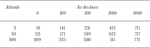
For the 4 MHz bandwidth of the present system, the best achievable across- and along-track (azimuth) resolution is 81 m. Since the aircraft velocity is around 70 m s−1, an azimuth sampling rate of about three samples per second is sufficient. A sampling interval of 320 ms has been selected.
A consequence of a large-resolution cell is the summation of echoes from a large area, which improves the sensitivity for weak echoes. For strong echoes, however, it is more significant that objects somewhat to the side of the flight track may be interpreted as being on the flight track (e.g. the closest object may not be exactly below the aircraft).
Surface reflections
A severe obstacle to thickness measurements of glaciers is the radar echo from the surface, especially when the surface is rough. Since the echoes from the surface are not subject to ice absorption, they will often be much stronger than those from the bottom of the glacier and they may completely mask the latter. This is especially problematic for a system without coherent signal-processing capability relying on a simple dipole antenna.
One countermeasure against surface echoes is to maintain a very low aircraft altitude during ice sounding since reflections (backscatter) from a surface are small at near 90° angle of incidence, especially when the roughness is small compared to the wavelength. The null in the antenna pattern along the dipole axis (i.e. perpendicular to the flight direction) also helps to suppress surface echoes at low aircraft altitudes.
The echo from a point target on the surface has a 3 dB extension of cr/2, i.e. 37.5 m in the present case. With an air-craft velocity of 70 m s−1 this corresponds to 0.5 s flight. Consequently, point targets straight ahead of the aircraft give echoes with 3 dB duration in azimuth of 0.5 s. Such echoes will be suppressed somewhat by the azimuth filter provided the filter bandwidth is ≤2 Hz. This effect will be reduced for point targets at angles of incidence of <90°; i.e. a low aircraft altitude is also preferred from this point of view.
In good weather conditions, aircraft altitudes down to 15 m are realistic over short distances, and 300 m is certainly safe except under foggy or cloudy conditions.
Radar mapping of the surface is requested when the laser altimeter is not operating, e.g. due to fog or low clouds. The transmitted pulse, including multiple reflections on the antenna feeder and the like, must decay to a level below the amplitude of the echoes before the echoes arrive. This gives a requirement for a minimum flight altitude. For the actual installation it proved necessary to fly 250 m above the surface to assure good detection of the echoes.
Data Acquisition and Pre-Processing
The data acquisition has been implemented using a ruggedized portable personal computer (PC), capable of using the aircraft unregulated d.c. power, with a single data-acquisition extension board having a 12-bit, 10 MHz, analogue/digital converter and a digital signal processor (DSP).
The data-acquisition board digitizes and stores each range trace in a 512-sample buffer. The DSP takes care of the azimuth filtering, buffering of the data as required, and forwarding of the data to the PC at a rate of 3.125 traces per second, each with 512 samples in 32-bit U.S. Institute of Electrical and Electronic Engineers standard floating-point format.
The azimuth filter (which is actually 512 filters in parallel, one per range cell) is implemented in two stages in order to keep the processing requirements within the capacity of the single DSP. The first stage is a simple integrate-and-dump filter which reduces the data rate from 10 000 to 50 lines per second, i.e. a factor of 200. In order to suppress aliased noise and surface clutter, the second stage is implemented as a multiphase FIR decimation filter, which reduces the bandwidth by a factor of 32 and the data rate by a factor of 16. The effective number of averaged traces in this filter is 23, i. e. in total 4600 effective averaged traces.
The resulting data rate is 3.125 range traces per second, each with 512 range cells of 4 bytes (32 bits). This amounts to a total of 23 M bytes per hour which can easily be accommodated by a standard PC hard disk even for several days of data acquisition.
Online Software Support
The PC fetches the range traces from the extension board, stores the acquired data on disk, and displays the data on the screen after further online processing. It also acquires and stores the time and position information as measured directly by the GPS. The time information from the GPS is used offline to synchronize the radar data with the laser-altimeter data and the outcome of the kinematic GPS processing.
The online radar-screen display is split into two parts, one of which is for control and system monitoring. Here the GPS time is displayed, and the approximate ice thickness and aircraft altitude are displayed provided the operator identifies the proper echoes with the cursor. The operator can select additional azimuth filtering, offset in range (panning), and zoom of the data display. The large dynamic range of the data makes it virtually impossible for the operator to find weak bottom echoes on the screen unless the data have been highpass filtered in range. First-order differentiation, which enhances the steepest part of the leading edges of the echoes, and second-order differentiation can be selected.
An example of the radar-screen data display is shown in Figure 3. The lower part displays the (logarithmic, 70 dB range) echo amplitude vs echo delay. This section permits the operator to verify proper operation of the radar system. The upper part is a continuously scrolling image showing the latest 2 min (i.e. about 8.4 km flight distance) of echoes. Each time a range trace is acquired by the PC, the trace is processed, the image is pushed down one line, and the amplitude of the latest line is written as the intensity in the top line, i.e. a white vertical line will be a strong echo at a constant distance from the aircraft. The lines start at the left border a little before the leading edge of the transmitted pulse. The example shows the signal, first-order differentiated in range, with a factor 3 zoom. The arrows indicate the location of the leading edge of the transmitter pulse, the surface echo and the bottom echo, respectively. In addition, a second-order reflection is clearly visible due to the strong reflection at the ice/water interface. The uppermost line is the same as that displayed in the amplitude display beneath.
Example of radar-screen display from a part of the glacier analyzed for display in Figure 5.

The data-processing software in the PC also enables the operator to replay the data after the acquisition flight and to trace and record the echoes of interest. The operator may thus, while still in the field, perform a tentative analysis of the data and generate flight-track maps, ice-thickness maps, etc., to verify that the desired information has been obtained.
Results from a Preliminary Data Processing
Nioghalvfjerdsfjorden glacier (79°30′ N, 21° W), a large outlet glacier from the northeast Greenland ice sheet, is about 80 km long and >20 km wide (Fig. 4). The outer 60 km of the glacier, which consists of solid ice, is afloat. Fieldwork on the glacier was carried out during the period 1996–98 by the Geological Survey of Denmark and Greenland (GEUS), the Danish Polar Center (DPC), the Alfred Wegener Institute for Polar and Marine Research (AWI) and the Danish Center for Remote Sensing (Reference Thomsen, Reeh, Olesen, Starzer and BøggildThomsen and others, 1999). The study, aiming at assessing the mass balance, dynamics and stability of the floating glacier, comprised observations of climate, surface mass balance and velocity, and measurements of the melting from the bottom of the glacier.
Map of Nioghalvfjerdsfjorden glacier showing radar profile, GPS reference site, location of tide gauge and glacier grounding zone. The arrow on the inserted map of Greenland shows the glacier location.

In July 1998, about 3000 km of high-quality surface and ice-thickness profiles were acquired on Nioghalvfjerdsfjorden glacier with the system. The aircraft altitude was in most cases 270–280 m above the glacier. The horizontal spacing between the flight tracks was about 5 km on the relatively uniform floating part of the glacier, but was decreased to about 2.5 km in the grounding zone.
An example of the result of a preliminary processing of the radar and laser-altimeter data is shown in Figure 5. GPS-measured altitudes in World Geodetic System 1984 coordinates are converted to altitudes above sea level by using a geoid height of 29.2 ± 0.1 m obtained by GPS measurement to the local mean sea level as determined from two 1 month long tidal records, for July/August 1997 and July/August 1998.
(a) Upper curve: Floating glacier surface altitude in meters above mean sea level measured by laser altimeter. Lower curve: Difference between laser-altimeter and radar surface altitude measurement. (b) Surface and bottom profiles. The ridge discussed in the text is situated near distance 2 km. (c) The ratio between surface altitude and ice thickness.

Figure 5a shows the surface-altitude profile in a cross-section of the floating part of Nioghalvfjerdsfjorden glacier as measured by laser altimeter (upper curve), and the difference between this profile and the corresponding profile measured by radar. The radar altitudes were reduced by 6.1 m, the mean difference between the two measured profiles. This corresponds to a radar-range time offset of approximately 40 ns caused by the limited rise time of the radar pulse in combination with the different amplitude of the transmitted pulse and the surface echo. With this adjustment, the two profiles are in excellent agreement on length scales of >500 m. The smooth discrepancies occurring at shorter spatial wavelengths can be explained by the much larger footprint of the radar measurement. The spikes can be ascribed to radar-echo amplitude fluctuations and off-the-flight-track surface variations combined with the 3.75 m (25 ns two-way propagation in air at zoom factor 4) quantization of the measured radar altitude, and could be removed by low-pass filtering in azimuth.
Figure 5a verifies that the radar correctly picks up the essential surface features with spatial wavelengths larger than about 500 m. This is important because it demonstrates that the airborne system will function also under cloudy/foggy weather conditions, prohibitive for laser measurements, without losing too much information about the surface.
Figure 5b shows surface and bottom profiles of the cross-section. The bottom profile is determined by subtracting ice thickness from the more accurate of the surface profiles, i.e. the profile obtained by laser-altimeter measurements. The profile illustrates the large ice-thickness variations (200–400 m) in the cross-profile. The figure also illustrates a clear correspondence between surface altitude and ice thickness, with thicker ice beneath the more elevated surface sections. This is further illustrated in Figure 5c, displaying the ratio d i between the laser-altimeter-determined surface altitude h and sounder-determined ice thickness H. Disregarding the high values at the start and end of the profile indicating grounded ice, the average value of d i is found to be 0.110. The value of d i, derived as the ratio between in situ measurements of h (determined by GPS measurement relative to sea level) and H (determined by direct measurement in a borehole drilled through the ice) is 0.108 ± 0.002 (Reference Olesen, Thomsen, Reeh, Bøggild, Dowdeswell, Dowdeswell and HagenOlesen and others, 1998), suggesting that the ratio d i = h/H as determined by our airborne system has an uncertainty on the order of 0.110 – 0.108 = 0.002, i.e. a relative uncertainty on the order of 0.02. Hence,

where σh and σH denote the uncertainties of h and H, respectively. As h ≈ 35 m and H ≈ 325 m, this expression shows that σh and σH can be estimated not to exceed 0.6 and 6 m, respectively.
The glaciological interpretation of the surface and bottom profiles will be discussed in detail elsewhere. An application of the results is shown by Reference Reeh, Mayer, Olesen, Christensen and ThomsenReeh and others (in press). Here we shall mention only that the pronounced spike in the laser surface profile (Fig. 5a near distance 2 km) images the crossing of a narrow ridge (approximately 30 m high) running roughly parallel with the glacier margin. The feature is also seen by the radar (Fig. 3 shows approximately the first third of the track in Fig. 5), but as a smaller spike due to the small extension and the larger radar footprint, and slightly delayed due to the azimuth filter. Figure 5b shows a similar narrow trough in the bottom surface, which is an artefact caused by surface elevation measured by the laser and the almost constant ice thickness measured by the radar. The local depressions of the surface on either side of the ridge (Fig. 5a) and the associated locally decreased values of the ratio d i (Fig. 5c) suggest that the weight of the ridge is not locally balanced by a keel but is distributed over a certain area of the glacier by bending action.
Inspection of the radar display (Fig. 3) reveals that the bottom echo vanishes just beneath the ridge, indicating a poorly defined bottom interface or excessive surface scattering due to the ridge. Between the ridge and the glacier margin (at the lowest part of the scrolled image) the bottom echo is weak and the second-order reflection is not visible, suggesting that the glacier is grounded all the way to the ridge although almost afloat according to the value of d i. These observations make it tempting to assume that the ridge is caused by the edge of a rock shelf in combination with the ice flow and/or the tidal movements.
Acknowledgements
The fieldwork was carried out under contract ENV4-CT095-0124 with the European Commission Fourth Framework Programme “Climate and Environment”. P Sørensen and B. Brændstrup are acknowledged for their contribution to the design and construction of the electronics synchronizing the radar with the data-acquisition unit. J. Dall assisted in preparing the flight plan. W. Starzer of GEUS contributed to the development of the semi-automatic offline processing software. The reviewers are acknowledged for their useful suggestions for improving the manuscript.



