
1.1 Space Exploration: The Unmanned Spacecraft That Ventured into Space
The dream of exploring the space surrounding the Earth has been around for many hundreds of years. Space exploration needed rockets to go to space, and engineers such as the Russian Konstantin Tsiolkovsky, the German Herman Oberth, and the American Robert H. Goddard were among many who successfully attempted to build rockets for space travel. The dream of space travel was fueled by such science fiction writers as Cyrano de Bergerac (1619–1655), Jules Verne, who published his novel From the Earth to the Moon in 1865, and H. G. Wells, whose novel First Men on the Moon was published in 1901, and these works inspired scientists such as Robert H. Goddard and Werner von Braun, who led the US effort to send an astronaut to the Moon. On the October 4, 1957 the Soviet Union launched the first autonomous artificial satellite, Sputnik 1, illustrated in Figure 1.1, which orbited the Earth in 96.2 minutes in an elliptic orbit at an inclination of 65 degrees.
Sputnik 1.
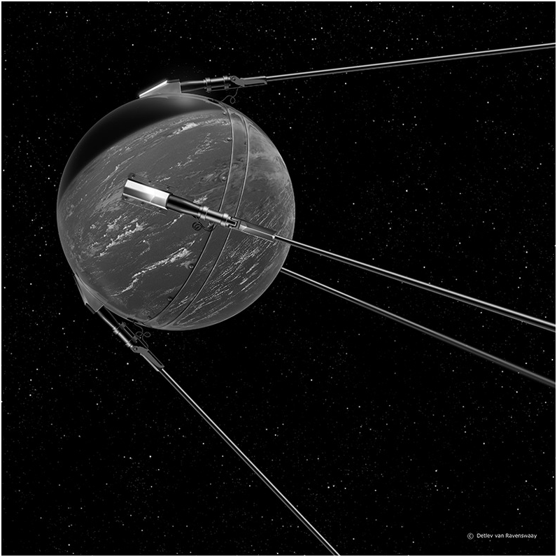
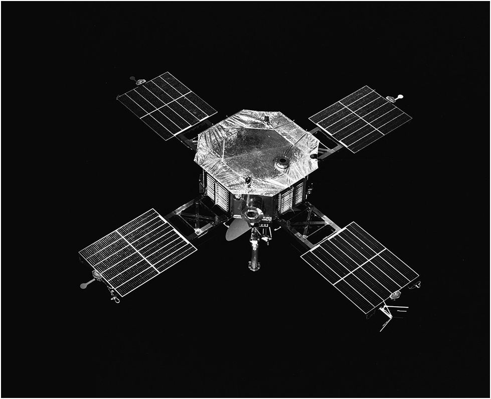
The satellite was 58 cm in diameter and orbited the Earth at the rate of 8,100 m/s for three weeks before its batteries ran out of power. It was launched on board a Soviet R7 rocket that was just over 29 m long and developed a thrust of 3.9 mega Newtons. It crashed back to Earth six months after its launch. Soon afterward, the Soviet Union launched Sputnik 2 with a dog on board. Unfortunately, the dog did not survive the flight, although it spent a week in Earth orbit. In 1958 the Explorer 1 satellite that was responsible for detecting the radiation belts around the Earth was launched by the United States. The first US communications satellite, Telstar 1, was launched in July 1962. Over 3,000 satellites have been launched since then for communication and navigation applications, weather observation, space and deep space research, and military applications. The first successful space probe was Luna 2, which crashed on the Moon in 1959. After this, several other Luna spacecraft visited the Moon, the Mariner series of spacecraft visited the planets Venus, Mars, and Mercury, while the Pioneer 10 and 11 spacecraft visited the planets Jupiter and Saturn, respectively. Early Pioneer spacecraft were used to launch probes that landed on the surface of Venus. Figure 1.2 illustrates Mariner 5, built as a back-up for Mariner 4, the first spacecraft to go to Mars, which eventually went on to probe the planet Venus.
The Mariner 5 spacecraft en route to the planet Venus.

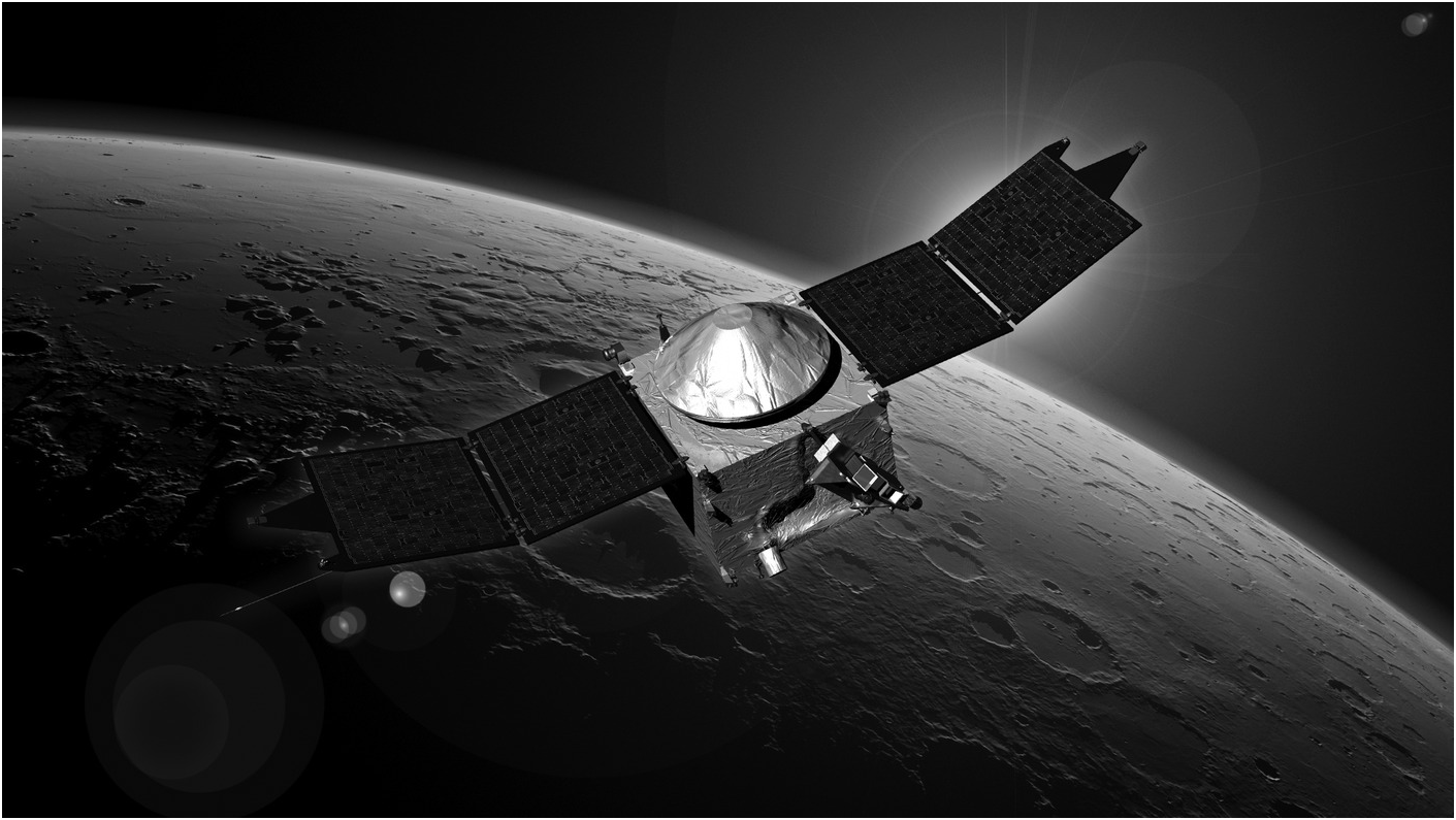
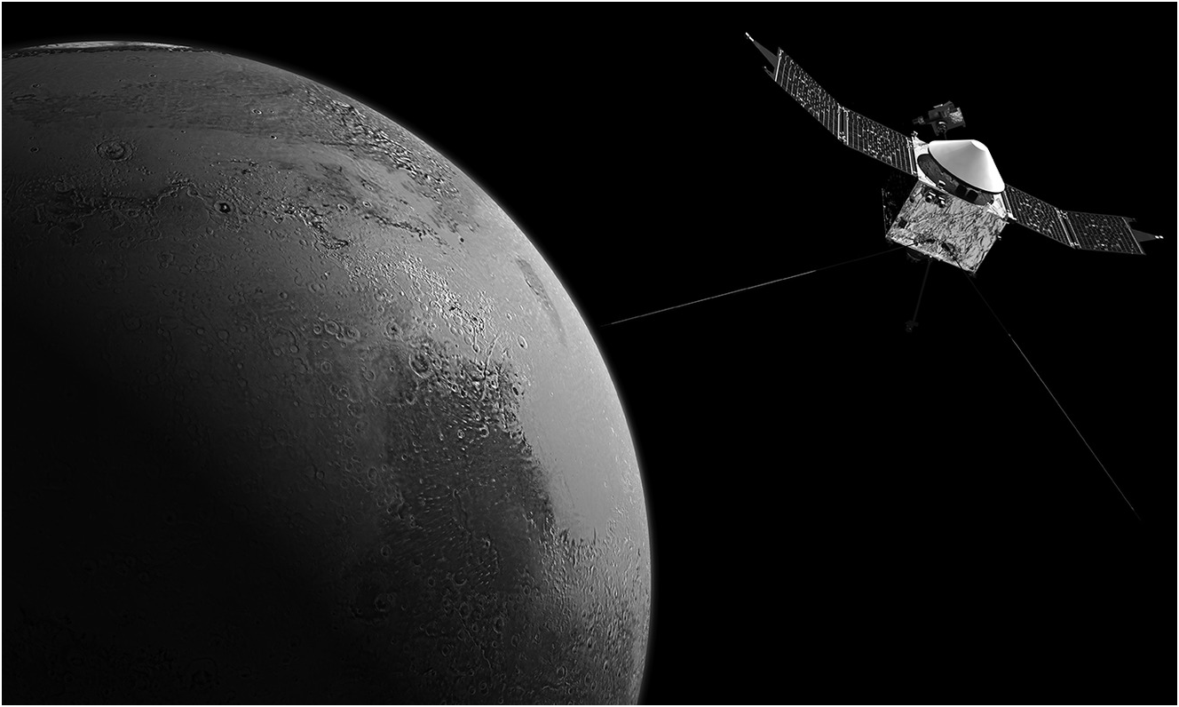
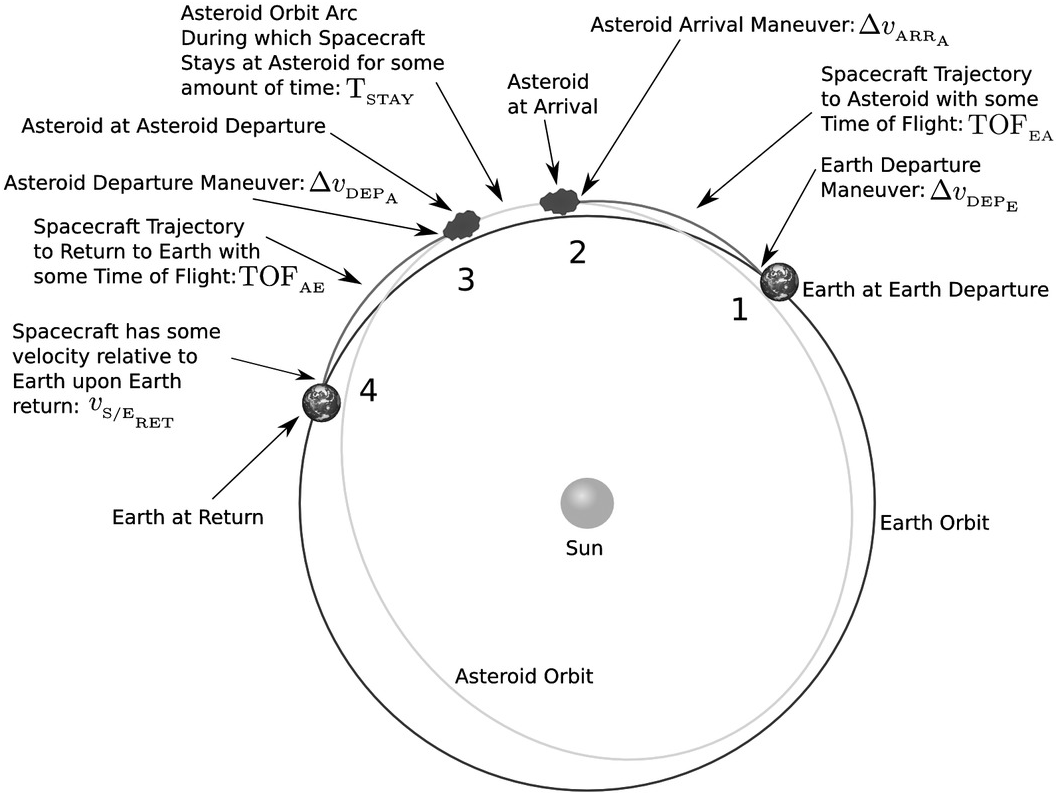
The outer planets Uranus and Neptune were visited by Voyager 2 in 1986 and 1989, respectively. The asteroid Gaspra was examined by the US spacecraft Galileo, while the European spacecraft Giotto surveyed Halley’s comet. Figure 1.3 illustrates NASA’s STARDUST spacecraft, which was launched in 1999, en route to the comet Tempel 1, following a NASA spacecraft’s successful fly-by of the comet Hartley 2. NASA’s Mars Atmosphere and Volatile Evolution (MAVEN) satellite, which began orbiting Mars in September 2014, was designed to fly-by the comet C/2013 A1 Siding Spring and is shown in Figure 1.4. The Near Earth Asteroid Rendezvous (NEAR) satellite mission profile and its journey to the Asteroid 433 EROS, which involved several Deep Space Maneuvers (DSM) that were executed shortly after the asteroid 253 Mathilde fly-by, on July 3, 1997, is shown in Figure 1.5.
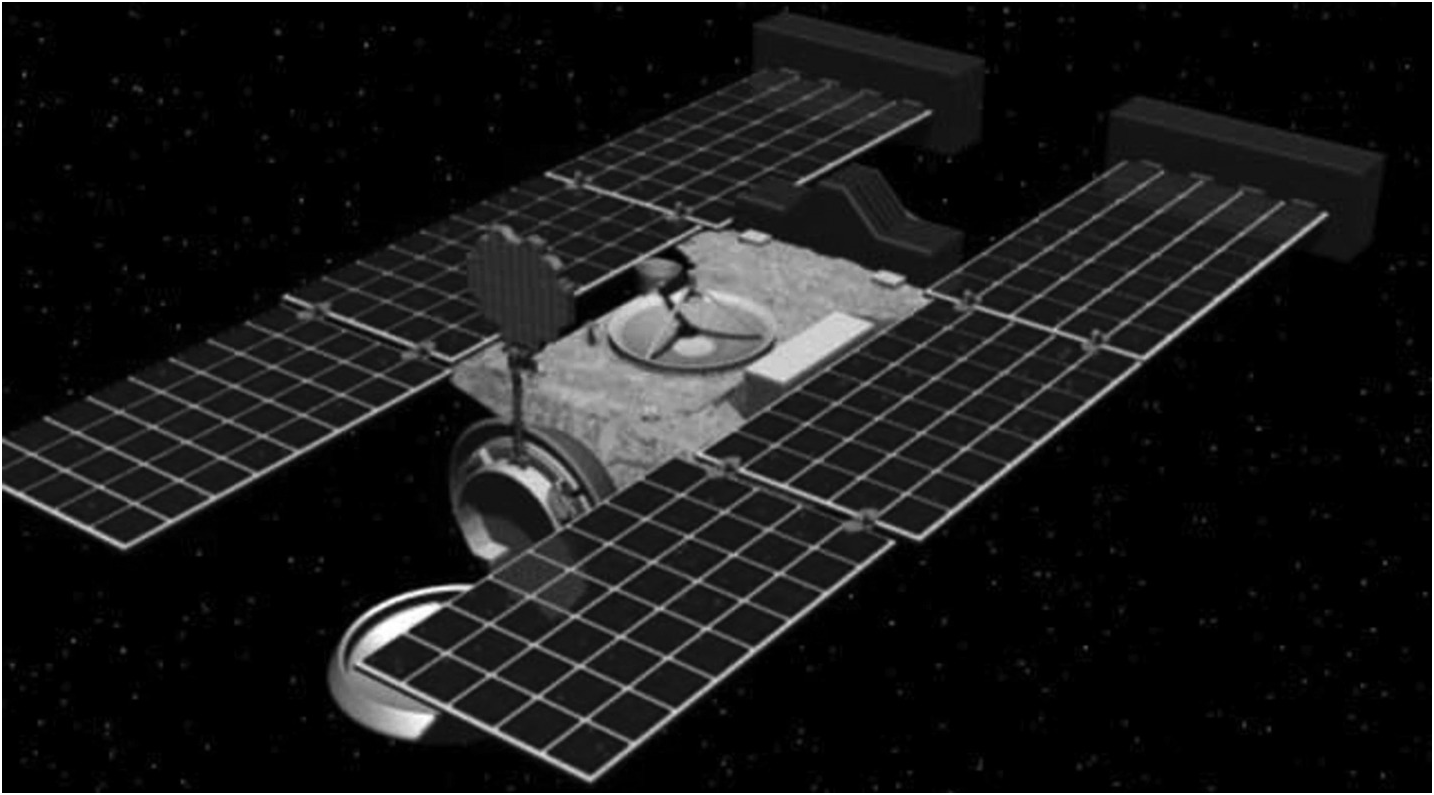
NASA’s Mars Atmosphere and Volatile Evolution (MAVEN) satellite orbiting Mars after a Comet fly-by.

The diagram illustrates the parts of a conceptual mission to the asteroid. The outer oval represents Earth’s orbit, the inner oval is the asteroid’s orbit, and the red arcs are the spacecraft’s trajectory to and from the asteroid.
Using a novel slingshot maneuver around the planet Jupiter, the Ulysses spacecraft was redirected to the Sun and it passed by the Sun’s North Pole in 1995. The first planetary rovers, known as Lunokhods and illustrated in Figure 1.6, were landed on the Moon by the Soviet Union between 1970 and 1973.
The Lunokhod Moon rover.
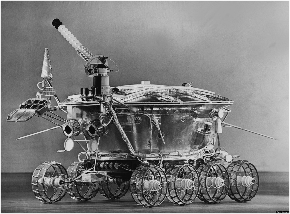
Figure 1.7 shows the space shuttle Endeavour docked with the International Space Station (ISS) [Reference Liedahl, Libby and Rubenchik1].
Space shuttle Endeavour docked with the International Space Station.
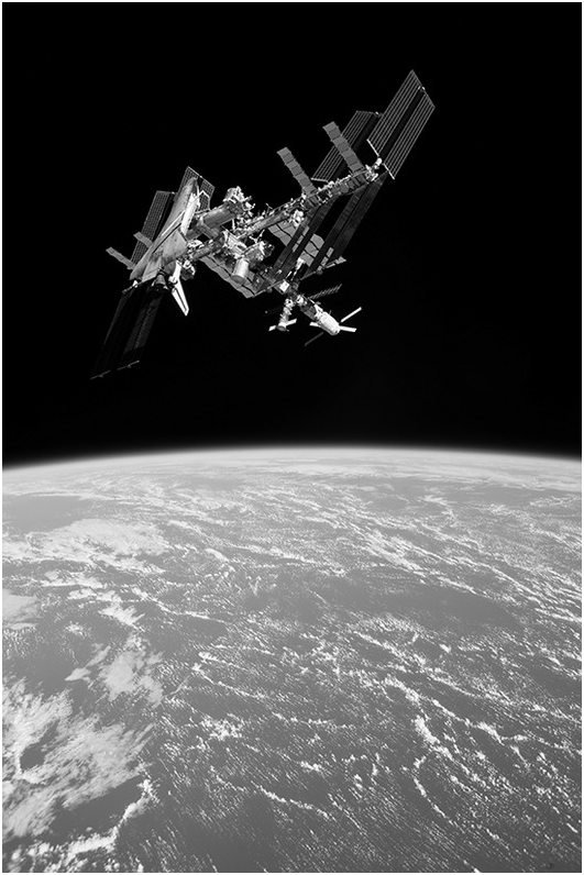
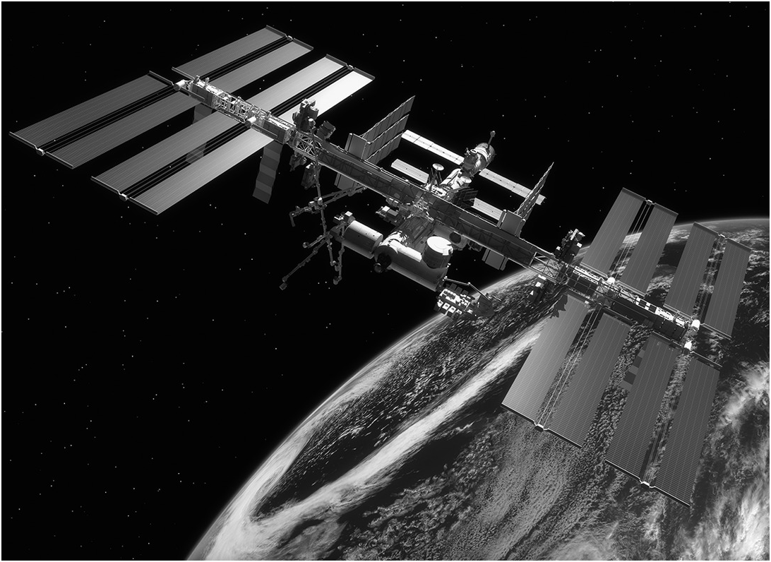
Although space exploration is extremely expensive, countries like China and India have also designed and launched low-cost missions to the Moon and Mars. Almost all of these spacecraft were autonomous. The ISS, led by the United States, involved the use of robotic manipulators in space to assemble several modules over several years to make the design and deployment of a permanent artificial orbiting outpost in space, about 400 km above the Earth and moving at the rate of 7.7 km/s, a reality. A space shuttle fitted with a robotic arm was used to shuttle modules from the Earth for assembly and deployment on the ISS. The ISS, illustrated in Figure 1.8, was assembled using several robotic manipulators and was truly an international effort. The ISS and the space shuttle successfully demonstrated the use of tele-operated and autonomous robots in space.

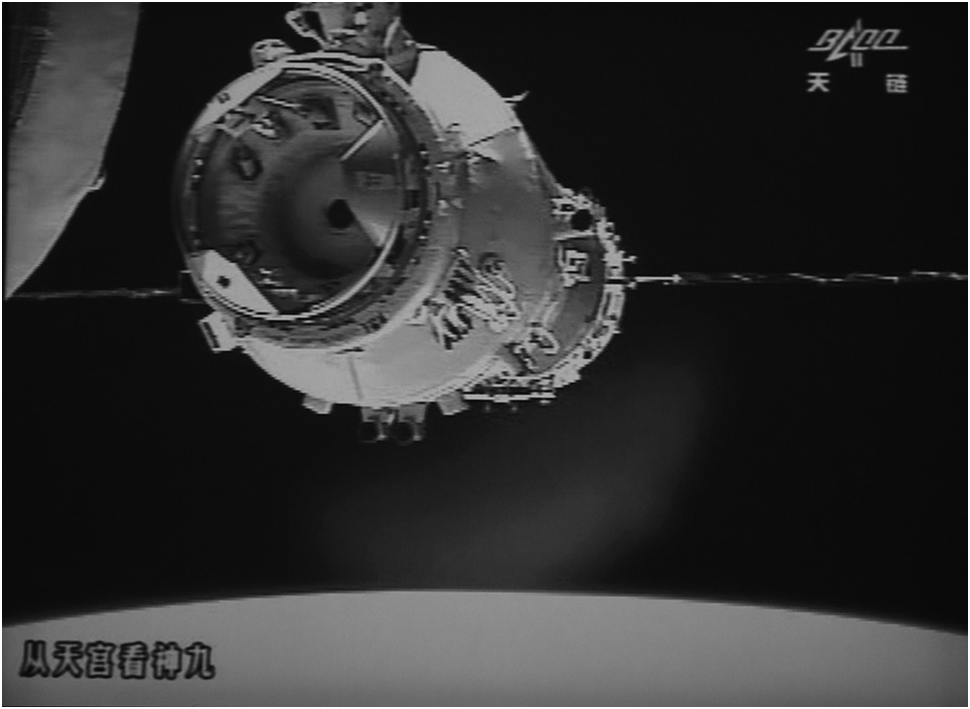
Apart from the US National Aeronautics and Space Administration (NASA), the Russian Federal Space Agency (ROSCOSMOS), and the European Space Agency (ESA), the Japan Aerospace Exploration Agency (JAXA), the China National Space Administration, and the Indian Space Research Organization (ISRO) have also been active in launching satellites. Figure 1.9 illustrates a Chinese satellite preparing to dock with a Chinese space station.
A Chinese satellite preparing to dock with a Chinese space station.

In another development, Arthur C. Clarke predicted in 1945 that satellites could be used for terrestrial communications in an article first published in Wireless World magazine in 1945. The first commercial communications satellite, Intelsat 1, was launched 20 years later in April 1965. Following the launch of the first communication satellite in 1962, proposals were made to develop radio navigation systems similar in principle to LORAN and DECCA but with satellite transmissions of precise radio navigation signals. This led to the development of the TRANSIT system, involving seven orbiting satellites, where the position of the user was determined from the Doppler shift in the received radio frequency signal. TRANSIT was made available in 1967 and soon after led to the development of the GPS system. After 10 years of development, proposals for establishing the GPS system were approved in the 1970s and the system was made available on a selective basis in the 1980s. Since the 1990s the GPS navigation system has been made available internationally for navigation applications worldwide.
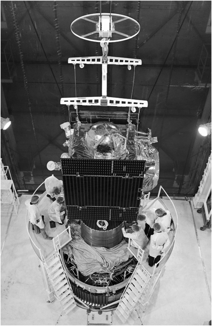
Besides the United States’ GPS (with 24 satellites in a constellation, orbiting the Earth at an altitude of 20,200 km), Russia’s GLONASS, and the European Union’s Galileo, the Indian Space Research Organization launched the Indian Regional Navigation Satellite System (IRNSS) satellites, a set of 7 dedicated satellites, in 2016, which form the NavIC (Navigation with Indian Constellation) system for navigation applications. Operating on dual frequency bands using the S and L bands, the NavIC system covers a limited region over the Indian subcontinent. Four of the satellites are geosynchronous, orbiting in pairs so the ground track looks like a figure of eight, north and south of the equator, while the remaining three are geostationary, all orbiting the Earth in a circular orbit at an altitude of 35,787 km above the equator. The Indian space research establishment crossed a major threshold when for the first time a factory owned by the private sector became involved in making a full multi-million dollar navigation satellite. In Figure 1.10, a typical IRNSS satellite is shown being assembled in a factory in Bangalore, India.
A typical IRNSS satellite is shown being assembled in a factory in Bangalore, India.
The use of the dual frequency band permits corrections to be easily made for transmission times due to atmospheric and tropospheric delays. The deployment of the system demonstrated the feasibility of developing and installing a system that can provide limited navigation coverage over any planet. The China National Space Administration is also in the process of building its own satellite navigation system known as the Beidou Navigation Satellite System.
1.2 Exploring Mars
Mars is one of the most enigmatic planets and a neighbor of our own planet. The manned Apollo 11 mission to the Moon landed on the lunar surface on July 20, 1969 almost 10 years after the first unmanned lunar landing by a Luna spacecraft. After the successful landing on the Moon, the attention of almost all space researchers turned back to Mars, which had evoked considerable interest from scientists in the early 1900s. It was believed, at that time, that Mars was inhabited and that there were large canals on the surface that were filled with water. This was later considered to be an illusion and probably caused by the reflection of the blood vessels in the human eye in a telescope’s eyepiece as astronomers viewed the surface of Mars. However, the more recent discovery of “ghost dunes” by the Mars Reconnaissance Orbiter seems to indicate the presence of extreme environmental conditions (winds and dust storms coupled with extreme temperatures), which seem to be responsible for creating special features on the surface of Mars.
Mars has an equatorial diameter of 6,759 km in comparison to the corresponding equatorial diameter of Earth of 12,756 km, which makes the Earth’s diameter almost 1.88 times the diameter of Mars. Mars’ orbital period is 687 days, making it also about 1.88 times the orbital period of the Earth (365.25 days). Mars’ mean orbital distance from the Sun is 227.94 million km, while the corresponding distance of the Earth is 149.59797 million km, making the distance of Mars about 1.52 times that of Earth or about 1.88 raised to the power of 2/3. The eccentricity of the Martian orbit is a lot greater (0.093) than that of the Earth (0.0167), which makes it 5.57 times that of the Earth. The inclination of Mars’ orbit is just less than 2 degrees that of the Earth, while the inclination of the Martian equator is slightly greater than the inclination of Earth’s equator to its orbit. Yet the mean density of Mars is only 71.3% of that of Earth, while acceleration due to gravity on the surface of the planet is 3.71 m/s2, which in comparison to the corresponding value on the surface of the Earth (9.81 m/s2) is less than 38%. Moreover, Mars has two moons, Phobos and Deimos, orbiting it at distances of 9,370 and 23,460 km, respectively, from its center. Another interesting feature of Mars as seen from Earth, due to its much larger orbital period, is that it appears to briefly move backward as it journeys from one end of the sky to the other.
Following the Mariner 9 spacecraft’s visit to Mars in 1971, two Viking spacecraft, Viking 1 and Viking 2, had landed on its surface in 1976 and transmitted pictures of the Martian surface. In 1996, NASA launched Mars Pathfinder and Mars Global Surveyor followed by Mars Odyssey in 2001. It was named in honor of Arthur C. Clarke’s novel entitled 2001: A Space Odyssey and reached Mars in just over six months. The spacecraft returned pictures of the surface of Mars in stunning detail and set the scene for the launch of spacecraft carrying the twin planetary exploration rovers and the planetary science laboratory in the years that followed.
Mars Express Orbiter, a cube-shaped satellite with two sets of solar panels on either side, was launched by the European Space Agency in June 2003 and arrived in the Martian environment in December 2003, after a six-month journey covering the 400 million km distance. Mars Express Orbiter is the second longest surviving, continually active spacecraft in orbit around a planet other than Earth. Although it was accompanied by Beagle 2, a Mars lander that failed to deploy properly after a successful landing, Mars Express Orbiter has now continuously surveyed the structure of the Martian surface for over a decade and in July 2018 it was reported that it had discovered a 12-mile-wide lake containing liquid water beneath the Martian surface, thus indicating the possibility of some life forms existing on the planet.
The Mars Reconnaissance Orbiter was launched in 2005, following the launch of the Mars exploration rovers, Spirit and Opportunity, and was fully focused on its mission almost 13 months later. The Mars Science Laboratory was launched in 2011, culminating in the landing of the Curiosity rover on the surface of Mars in 2012.
1.3 Robotic Spacecraft for Planetary Landing and Exploration
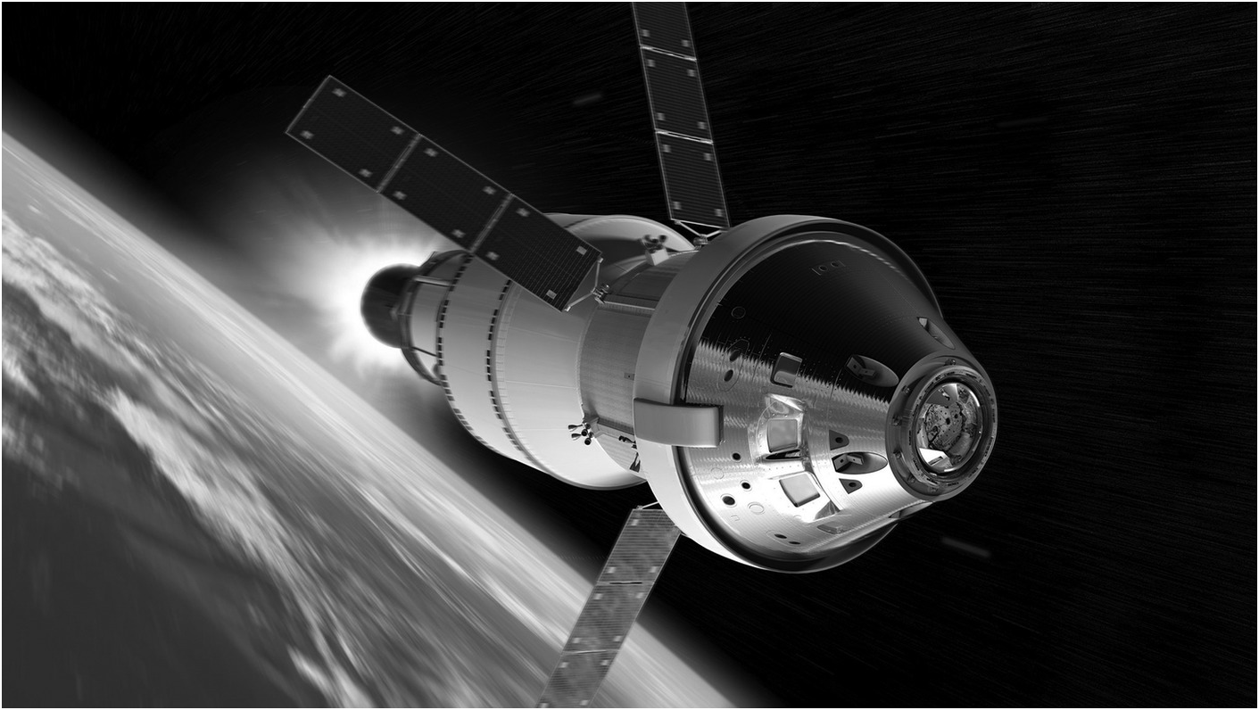
While NASA’s Mariner 2 was the first spacecraft to reach the planet Venus, it was the Soviet Union’s Venera 3 that made the first landing on the surface of that planet. The first manned spacecraft to land on the surface of the Moon was the Lunar module, which left its mother ship, Apollo 11, while it was in a lunar orbit and landed on the lunar surface. NASA plans a return to the lunar surface in the years to come. To realize this project, NASA is launching a satellite, Orion, which will fly approximately 100 km above the surface of the Moon, and then use the Moon’s gravitational force to move itself into a new deep space orbit. The Orion mission is the first of a series of launches that are designed to explore deep space. Figure 1.11 is an illustration of the Orion spacecraft in lunar orbit.
The Orion spacecraft.
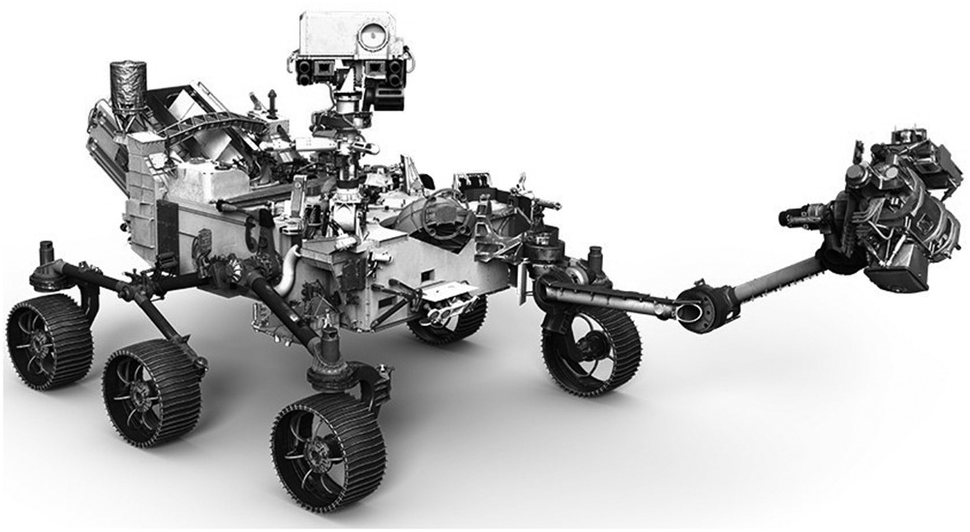
More than 30 missions worldwide have been launched by several countries to explore the Martian environment. Several of these missions have been responsible for taking Martian planetary landers and rovers, such as Pathfinder, Spirit, Opportunity, and Curiosity, and landing them safely on the Martian surface. The latest mission planned as part of the ExoMars program are an Orbiter plus an Entry, Descent, and Landing Demonstrator Module, which was launched in 2016. Figure 1.12 is an artist’s impression of a satellite approaching the planet Mars. Another launch, featuring a new rover, with a launch date in 2020, is also planned. Figure 1.13 is an illustration of the proposed new rover that is to be sent to bring back a rock from the surface of Mars.
A satellite approaching the planet Mars.

The proposed new Mars rover.

1.4 Exploring a Comet
NASA JPL’s Deep Space 1 mission in 1998, on its way to an asteroid and then to a comet, was the first satellite to be powered by an electric propulsion system, using an electrostatic ion thruster that generates thrust by accelerating charged particles or ions by creating electrostatic fields. The European Space Agency tested an electric propulsion system in space on NASA’s Artemis spacecraft in 2001. Japan’s Hayabusa spacecraft used ion electric propulsion in 2003 for an asteroid sample capture and return mission.
Ion electric propulsion is characterized by high specific impulse, which is the momentum added to the spacecraft per unit weight (on Earth) of the propellant (usually Argon, Xenon, or Krypton). Thus, although ion electric propulsion generates low thrust, its endurance is practically very high and can be used for very long periods of time, making it suitable for deep space missions. The variable specific impulse magneto-plasma rockets provide much higher thrusts and can bridge the gap between high thrust chemical propulsion and low thrust electrostatic ion propulsion.
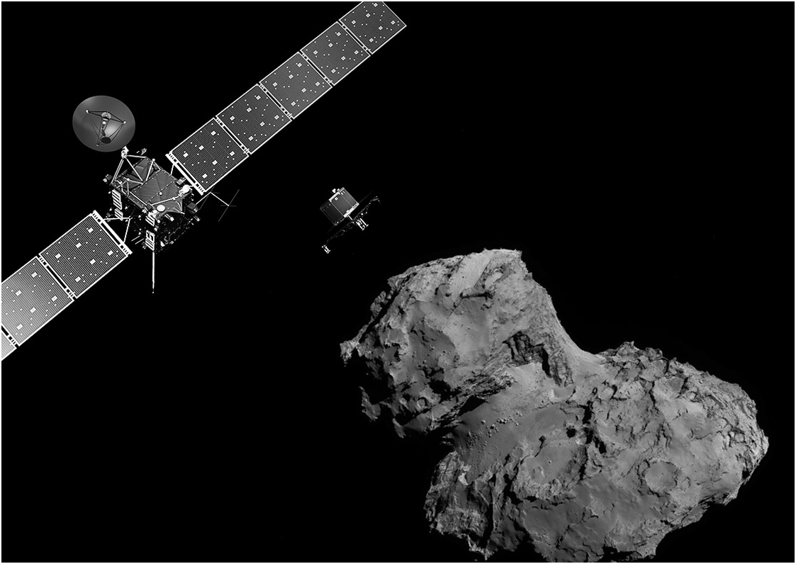
In 2014, history was made with the first ever landing of a lander on a comet. In November of that year the European Space Agency’s Rosetta spacecraft dispatched a lander named Philae to the surface of the comet 67P/Churyumov-Gerasimenko in 2014, after a 10-year journey of the spacecraft and lander to its vicinity.
The mission revealed in incredible detail the structure of the cometary surface landscape as well as the presence of rocks of relatively large size. Figure 1.14 is an artist’s impression of the Rosetta mission.
An artist’s impression of the Rosetta satellite and the Philae lander approaching the comet.
1.5 Grabbing an Asteroid
Three new missions will return samples of asteroids to Earth for future study. JAXA launched its Hayabusa-2 mission, which will robotically collect samples of asteroid 1999JU3 in 2018 and return them to Earth in 2020. The mission builds on the legacy of JAXA’s earlier Hayabusa mission, which explored asteroid Itokawa and returned samples to Earth in 2010.
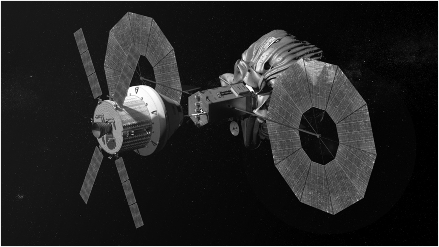
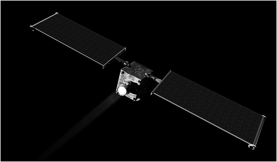
In 2016 NASA launched its robotic satellite mission, the Origins-Spectral Interpretation-Resource Identification-Security-Regolith Explorer (OSIRIS-Rex), to bring back a sample of an asteroid’s soil. The satellite is expected to rendezvous with asteroid 1999 RQ36, also known as “Bennu,” in 2019 and bring back samples to the Earth, arriving in 2023. The primary objectives for the mission include finding answers to basic questions about the composition of the very early solar system and the source of organic materials and water that made life possible on Earth. JAXA’s Hayabusa-2 and OSIRIS-Rex missions could help NASA to choose its target for the first-ever ambitious mission to capture and redirect an asteroid. NASA’s Asteroid Redirect Mission (ARM) in the 2020s will help NASA test new technologies needed for future human missions to Mars. For the ARM mission, NASA plans to launch a robotic spacecraft to first rendezvous with a near-Earth asteroid. The agency is weighing two concepts for what the spacecraft does next – one would fully capture a small asteroid about 5–10 m in size, using an inflatable mechanism, and the other would retrieve a boulder about 2–5 m (6–15 feet) in size from a much larger asteroid using a robotic arm. The spacecraft will then use the gentle thrust of its solar electric propulsion system and the gravity field of the Earth and Moon to redirect the asteroid into a stable orbit around the Moon, where astronauts will explore it in the mid-2020s, returning to Earth with samples much later. Figure 1.15 illustrates NASA’s Orion spacecraft approaching the robotic asteroid capture vehicle.
Satellite designed for Asteroid capture.

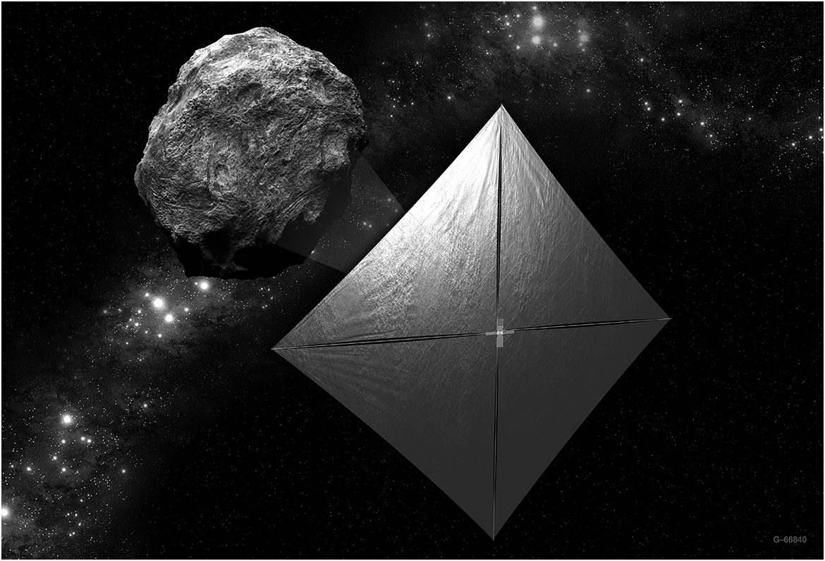
The Near Earth Asteroid Rendezvous – Shoemaker (NEAR Shoemaker), named after planetary scientist Eugene Shoemaker in 1996, was a robotic space probe designed by the Johns Hopkins University Applied Physics Laboratory for NASA to study near-Earth asteroids. The asteroid 253 Mathilde, which was discovered in 1885, is in the intermediate asteroid belt, and is approximately 50 km in diameter. The first image of asteroid 253 Mathilde was returned by the NEAR spacecraft in 1997. Figure 1.16 illustrates the NEA Scout CubeSat with its solar sail deployed as it maps a near-Earth asteroid.
NEA Scout CubeSat with its solar sail deployed as it maps a near-Earth asteroid.
1.6 Routing Space Debris
There is a growing concern about the amount of debris currently orbiting the Earth, which seems to be particularly concentrated around the geostationary circular orbit above the equator at particular locations along the orbit. According to the European Space Agency’s space debris office, there are more than 21,000 objects larger than 10 cm in orbit, while estimates of objects that are larger than 1 cm are in the region of 750,000. It has also been estimated that over 150 million smaller pieces of debris larger than 1 mm and 100 million pieces of debris less than 1 cm in size could be orbiting the Earth. Objects in low Earth orbit naturally decay due to the gradual loss of energy because of atmospheric drag, eventually falling to Earth. They usually get burnt up in the Earth’s atmosphere as they gain speed. This method of deorbiting is dependent upon several factors, including size, mass, material composition, and finally altitude. However, objects that are not in low Earth orbit could remain in orbit for as long as 2,000 years and pose a threat to future space missions. On March 13, 2009, when the ISS crew failed to anticipate space debris approaching the space station crew were forced into contingency operation. The ISS astronauts took cover in a Soyuz capsule to reduce the chance of penetration. The debris passed by the station at a safe distance and the crew was able to resume operations [Reference Bergin2]. Upon collision with objects in space, the production of debris is only increased and it can be seen that there is indeed a critical density of debris beyond which a serious threat to collision-free space travel is posed. Clearly, there is a need to look at the mitigation of the production of space debris, prediction of the rate at which it is generated, and control of the level of debris that actually exists in space at any given time.
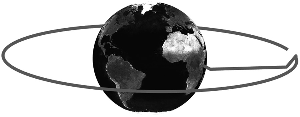
One approach to deorbit a piece of debris is to slow it down significantly so that, as a consequence of the loss of energy, the debris particle will lose altitude and eventually fall to the Earth. The danger of this approach is that an object in space may be mistakenly or deliberately construed as a piece of debris and destroyed, thus possibly sparking a war in space. Yet one method of slowing down an object in space is to fire a LASER in such a direction as to deorbit the object. Claude Phipps’s [Reference Phipps3, Reference Phipps4] early pioneering concept for space debris removal introduced in 1993 consists of a high-power pulsed, ground-based LASER system used to ablate a fraction of the debris in a specific orientation in order to slow it down. Essentially, this change of velocity would cause the debris to reenter the atmosphere and burn up. Space-based LASERS have also been considered, but a ground-based LASER system was expected to be more advantageous and simpler in operation and maintenance as well as lower on cost. Models have been constructed that allow one to simulate the trajectory of the debris before and after firing a LASER onto its surface. Such a simulation model would provide a useful tool for researchers in the field to investigate the application of LASERS to deorbiting space debris. Clearly, a basic requirement in order to do this is the availability of a catalogue of locations of space debris that is periodically updated. Levit and Marshall [Reference Levit and Marshall5] have catalogued and recorded the Two Line Element (TLE) orbital data for up to 3 million objects. Levit and Marshall [Reference Levit and Marshall5] suggest that a high-accuracy catalog based on the publicly available TLEs would be accurate enough to perform studies of changes in the orbital velocities below the cm/s range. Extending the work of Levit and Marshall [Reference Levit and Marshall5], Mason et al. [Reference Mason, Stupl, Marshall and Levit6] have catalogued data on debris objects to determine a reasonable area-mass ratio for debris. In Mason et al. [Reference Mason, Stupl, Marshall and Levit6] the importance of the area-mass ratio of debris objects that must be considered in modeling the orbiting object for LASER ablation is highlighted and a LASER ablation system based on available off-the-shelf LASER technology is proposed. Liedahl [Reference Liedahl, Rubenchik, Libby, Nikolaev and Phipps7] and Liedahl et al. [Reference Liedahl, Libby and Rubenchik1] have developed the area matrix approach for impulse transfer calculations for ablation of orbiting objects using LASERS and analyzed orbiting bodies of many shapes of space debris, which include cubic, cylindrical, and spherical bodies. While the momentum transfer would depend on the shape of the targeted debris, the analysis has been extended to arbitrarily shaped bodies. From the work of Campbell [Reference Campbell8] it is known that LASER interaction with a debris fragment will alter both the frequency and the orientation of the rotation vector. Wang, Zhang, and Wang [Reference Wang, Zhang and Wang9] have performed impulse calculations and characteristic analysis of space debris using pulsed LASER ablation. Based on this calculation, one can estimate the typical impulse requirements for deorbiting an irregular shaped object in orbit around the Earth. A typical simulated trajectory of such an object is shown in Figure 1.17.
Typical example of deorbiting a piece of debris orbiting the Earth.
1.7 Venturing into Deep Space: Spacecraft with Endurance
Voyager 1, which was launched on September 5, 1977, became the only spacecraft to have entered the space beyond the Solar system in 2012, after travelling some 13 billion miles away from the Earth. Voyager 2, launched on August 20, 1977, was the only spacecraft to have flown past all four outer planets of the Solar system – Jupiter, Saturn, Uranus, and Neptune – and also visited their moons; Io and Europa orbiting Jupiter, Saturn’s moon Titan, and Neptune’s moon Triton. It is clear that spacecraft will continue to explore far beyond the solar system in the years to come as several projects have been proposed to explore interstellar space.
The European Space Agency is expected to launch the JUpiter ICy moons Explorer or JUICE, as the mission has been named, which is intended to explore Jupiter and 3 of its estimated 79 moons. The first three of the four Galilean moons, Europa, Callisto, Ganymede, and Io, are expected to be surveyed by the JUICE mission. The orbital spacecraft, which will not be accompanied by a lander, is expected to be the first spacecraft to orbit Ganymede, almost eight years after its launch.
To facilitate deep space missions, NASA has been continuously testing the NASA Evolutionary Xenon Thruster (NEXT) ion engine for about six years – longer than any other space propulsion thruster tested by it. During this period it has consumed less than 10% of the fuel required by a chemically propelled thruster, thus demonstrating its long-term efficiency and its capacity to survive with low fuel consumption. Consequently, ion engines are expected to be the main work horses for future deep space missions.
1.8 Planetary Rovers and Robot Walkers, Hoppers, and Crawlers for Exploration
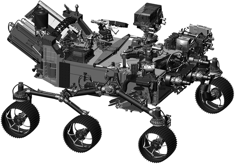
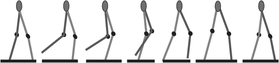
NASA scientists are testing the new six-wheeled solar-powered rover for future planetary missions, which will carry a host of instruments on board to carry out several missions on Mars. Figure 1.18 is an illustration of the new rover, intended to be a replacement for the rover Curiosity. There is also considerable interest in developing walking robot models that will accompany the planetary rovers. For the development of such walking robot models, simulators have been designed to test the swing and stance gait cycle in a remote planetary environment. Figure 1.19 illustrates a typical swing and stance gait cycle, based on Vepa [Reference Vepa, Tokhi and Virk10].
The new rover for future planetary missions.

Illustration of the swing and stance gait cycle implemented on a robot model.
1.9 Underwater Rovers and Aquanauts
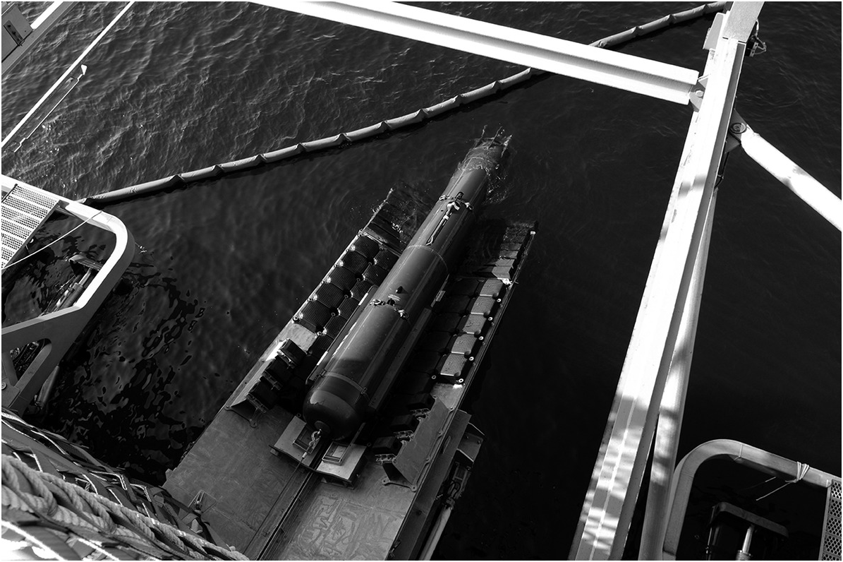
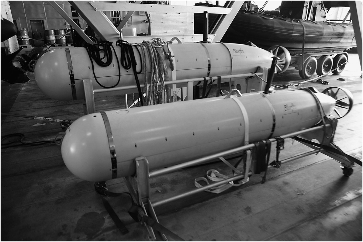
Remotely Operated Vehicles (ROVs) are essentially remote control submarines with cameras that enable one to navigate in the deep waters of the oceans. They can be used for a variety of applications such as off-shore construction, surveillance, underwater inspection, and a host of other applications. Figure 1.20 illustrates the Seahorse-class Autonomous Underwater Vehicle as it is moved into position for launch. In Figure 1.21 is an AUV, designed by Bluefin Robotics for the US Navy, being tested on July 12, 2004, to detect mines and other underwater hazards in waters off Hawaii.
The Seahorse-class Autonomous Underwater Vehicle is moved into position for launch.

AUV for underwater surveillance.
1.10 Humanoid Space Robots and Robonauts
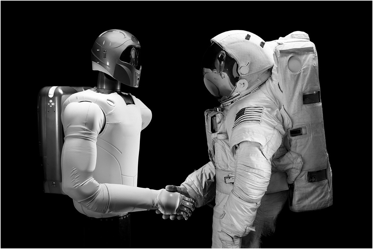
In order to work safely and reliably in the environment around a spacecraft while it is on a space mission, NASA has proposed to design and build a series of humanoid space robots or Robonauts. NASA’s Johnson Space Center, in Houston, Texas, produced the first Robonaut in 2000, which was only tested on Earth. Robonaut 2 was deployed on the ISS in February 2011. It was designed to work alongside the astronauts, to assist the crew with many of their time-consuming mechanical and repetitive chores, according to IEEE’s Spectrum. Robonaut 2 was first upgraded with a pair of legs in 2014 to provide it with additional mobility. In 2015 it developed several problems, and in February 2018, it was decided by NASA to bring it back to Earth for repairs. Figure 1.22 illustrates the Robonaut 2 performing its tasks on board the ISS.
Robonaut 2 meeting with an astronaut on board the International Space Station.

1.11 Robot Arms for Tele-Robotic Servicing
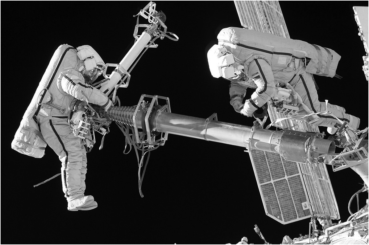
Generally, astronauts perform many chores outside a spacecraft while on a space mission. They could be assisted in this task by several robotic arms onboard the spacecraft. Figure 1.23 illustrates an astronaut anchored to the foot of Canadarm2, the robotic arm assisting the astronauts on the ISS. The ISS has several robotic arms on board to assist the astronauts. Canadarm2, also known as the Space Station Remote Manipulator System (SSRMS), was ferried to the ISS by the space shuttle Endeavour on April 19, 2001. It took about five days and a couple of spacewalks by the astronauts on board to install Canadarm2 on to the ISS. Since then, the arm has been used extensively outside of the space station, for transporting heavy payloads from one end of the space station to the other. Canadarm2 may be used to grab and dock approaching spacecraft, as and when they arrive at the space station. Flight controllers on the ground in Houston, Texas, can also operate Canadarm2 remotely, usually to assist and to relocate such pieces of equipment as a docking adapter to facilitate two or more spacewalks. The 18-m-long arm is one of three robotic components that now make up the space station’s Mobile Servicing System, along with a robotic dexterous “hand” known as Dextre. There is also a base platform known as the Mobile Remote Servicer Base System (MBS), which facilitates the motion of both Canadarm2 and Dextre in the environment in the vicinity of the space station’s spinal truss structure by sliding along a prismatic joint along the entire length of the space station.
An astronaut anchored to the foot of the Canadarm2 robotic arm.
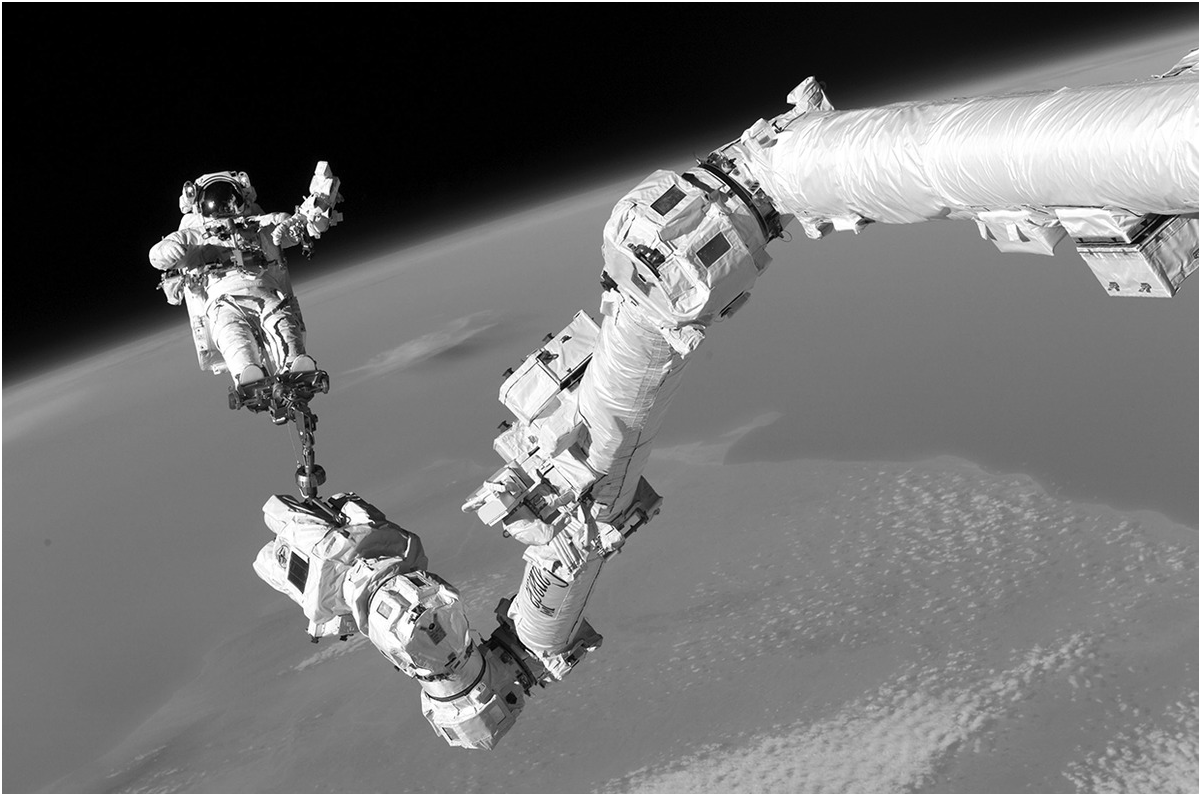
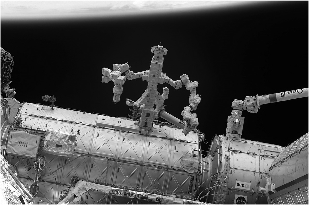
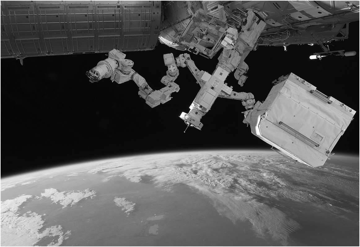
Figure 1.24 shows the Canadarm2 and Dextre in operation, performing their usual chores. Dextre is a remotely operated, dexterous special purpose manipulator weighing 1,500 kg that can be controlled either from inside the space station or from the ground station in Houston, Texas. The manipulator has seven joints in its arms, constituting shoulders, elbows, and wrists, which are configured for maximum reach. One arm holds on to the space station while the other is working. This ensures that the manipulator is balanced and stable and also ensures that there is no collision between the two arms. Its width across its shoulders is about 2.7 m; the length of one arm is 3.5 m and can handle payloads weighing up to 600 kg. The hand is endowed with a force-moment touch sensor so it can grasp an object with the correct controlled force. Dextre is capable of installing or removing small payloads such as batteries. Dextre is shown in Figure 1.25. NASA’s Double Asteroid Redirection Test (DART) spacecraft, which uses the NASA Evolutionary Xenon Thruster – Commercial (NEXT-C) solar electric propulsion system as its primary in-space propulsion system and is expected to be launched in late 2020 or in early 2021, is designed to demonstrate the kinetic impactor technique – a methodology to deliver an impact to the binary near-Earth asteroid (65803) Didymos to shift its orbit and to avoid a potential future collision with it. It is illustrated in Figure 1.26.
Canadarm2 and Dextre.
The Dextre special purpose dexterous manipulator.

NASA’s Double Asteroid Redirection Test (DART) spacecraft.

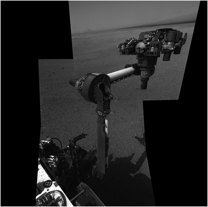
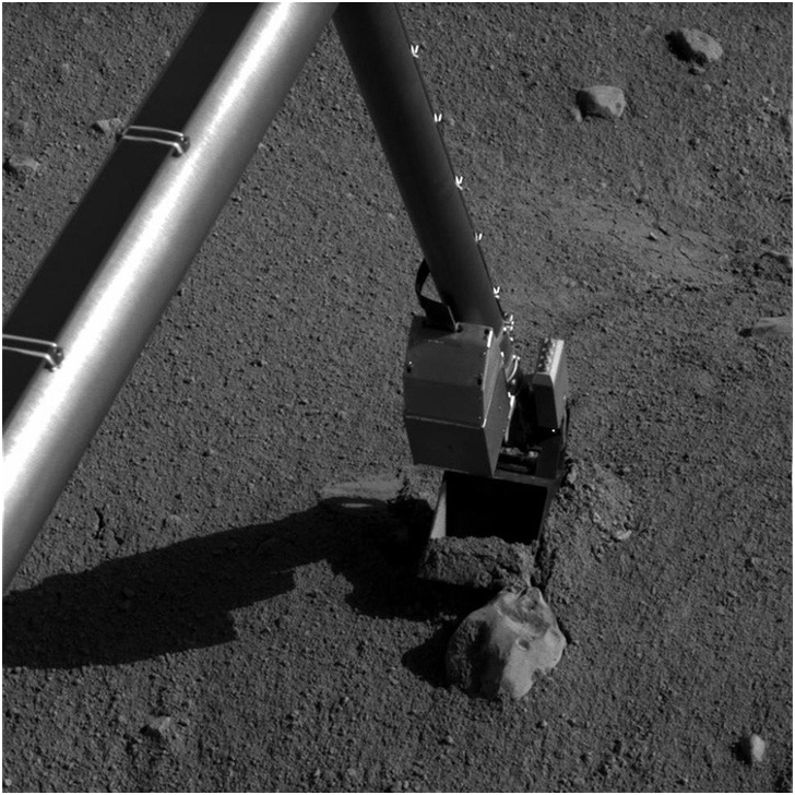
Also available on the space station are the European Space Agency’s 11-m-long, two-limb European Robotic Arm, which is designed to be used with the Russian segment of the space station. A third arm that is fixed on the Japanese Experiment Module, the Remote Manipulator System (JEM-RMS), uses a similar grapple fixture to Canadarm2. Figure 1.27 shows the extended 2.1-m-long robotic arm of NASA’s Mars rover Curiosity. Figure 1.28 shows the Phoenix robotic arm at work. The Phoenix manipulator is a 2.35-m-long arm, with an elbow joint in the middle, allowing the arm to dig about half a meter into the Martian surface and look for water or ice below the planet’s surface.
The extended 2.1-m-long robotic arm of NASA’s Mars rover Curiosity.
Also available on the space station is the Russian-built Strela robotic crane, used to lift and transport payloads in its vicinity. The Strela crane is shown in Figure 1.29 with two astronauts moving it into position.
The Strela crane being moved by two astronauts.

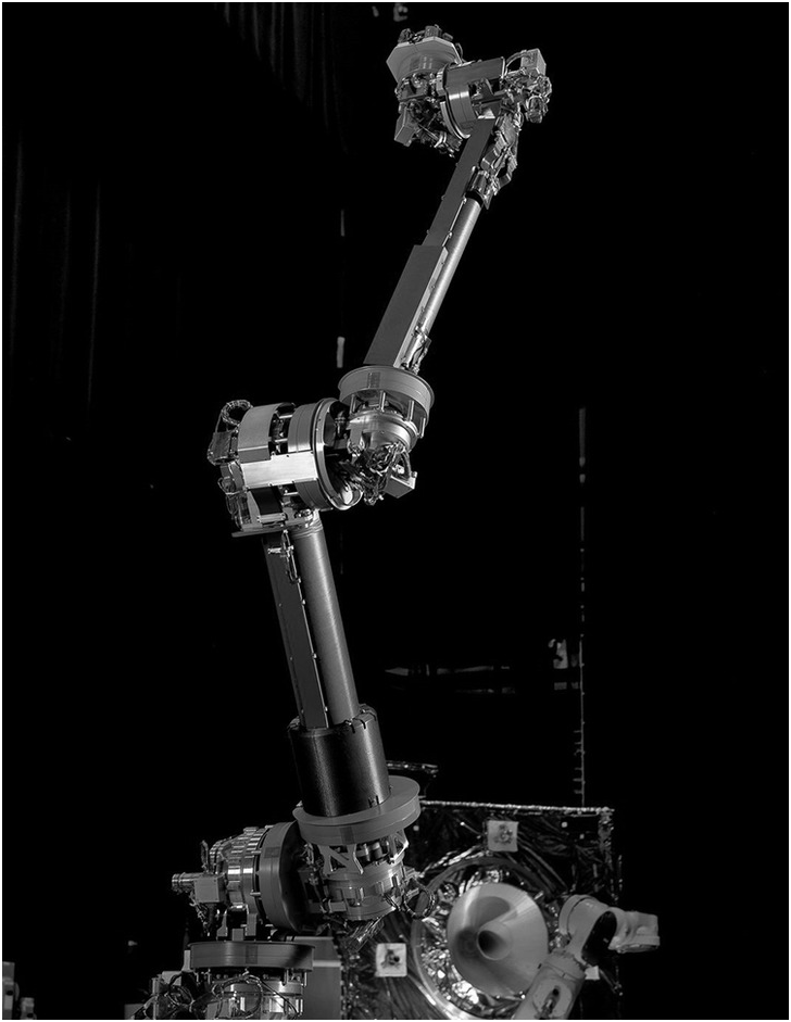
NASA’s robotic servicing arm, which, like a human arm, has seven degrees of freedom, a three-axis shoulder, a pitch actuator at the elbow, and a three-axis spherical wrist as well as a six-axis force torque sensor in the gripper, is shown in Figure 1.30.
NASA’s robotic servicing arm.

1.12 Tumbling Cubes
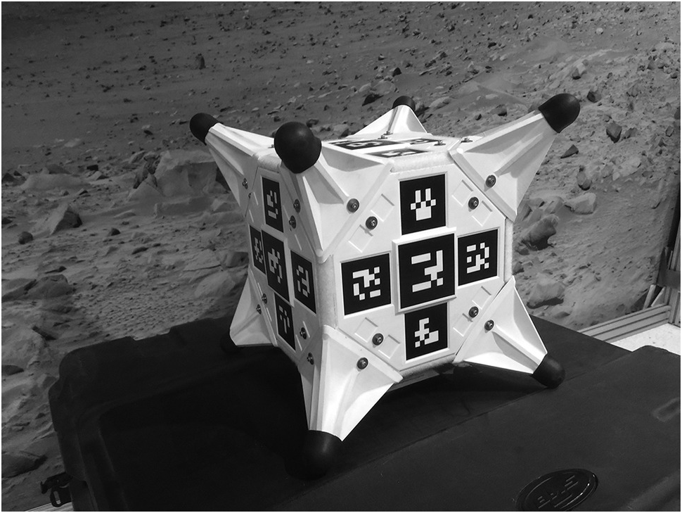
As part of its plan to grab an asteroid, NASA is also funding the Tumbling Cubes project, which involves the design, build, and test of robotic tumbling cubes that can move by themselves in a low-gravity environment that may exist on the surface of an asteroid. These cubical objects, known as “Hedgehog” robots, can move essentially by bouncing off the asteroid, which involves jumping up, balancing, and “walking.” The cubes contain a set of three flywheels rotating at high speed about three mutually perpendicular axes. The flywheels are used to generate moments acting on the cubes that facilitate the tumbling motion. An artist’s impression of the “Hedgehog” robot is shown in Figure 1.31.
The “Hedgehog” robot, which gets around by spinning and stopping three internal flywheels using motors and brakes.
1.13 Collaborative Robotic Systems
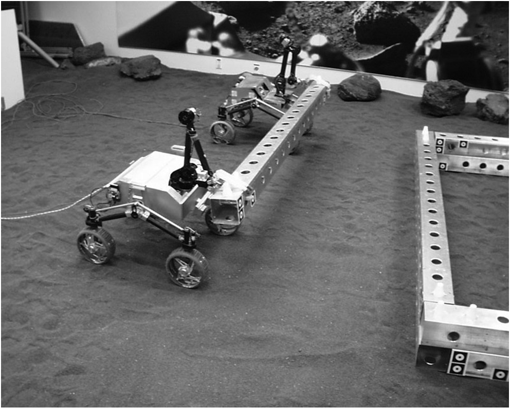
NASA is also funding the development of an ultra-light robotic system and advanced command and control software that is designed to make use of existing spacecraft equipment and capabilities, including a standard geostationary (GEO) spacecraft platform and processor, to host five or more robotic manipulator arms that will function as a semi-autonomous robotic system for in-space satellite and structures assembly. The NASA Jet Propulsion Laboratory’s Planetary Robotics Laboratory, a center for rapid prototyping of advanced robotic systems and the development of algorithms to control them in space, is researching multi-rover coordination for conceptual assembly operations on a planetary surface. A view of Jet Propulsion Laboratory’s research test bed is shown in Figure 1.32. This is an example of collaborative robotic systems, albeit on a small scale.
A view of the research test bed at the NASA Jet Propulsion Laboratory’s Planetary Robotics Laboratory.

1.14 The Meaning of Autonomy
Automatic control systems were introduced well before the Second World War, and the study of these systems was pioneered, among others, by the American engineers Harry Nyquist and Herman Bode. Almost always they involve the principle of feedback control and have evolved from the theory of servomechanisms, as they were known in the early days. Currently, there is considerable interest in the subject of autonomous control systems, and often the difference between the newer autonomous control systems and the classical automatic control systems is obscured. It is important to clearly understand the difference and also the uniquely characterizing features of autonomous control systems. First, autonomous systems arise from a synergy of various interacting subsystems. The principle of synergy is that that the sum is greater than the parts. A typical example is the mobile phone, which delivers a range of functions when all its interacting subsystems are assembled so the proper interaction between the subsystems is facilitated. In a classical automatic control system, decision making is done outside the controller. Generally, the controller is under the supervision of the operator in the sense that the set points and plans are set by the operator. There is no possibility of situational or spatial awareness, and it is also generally true that the controller has limited authority. A classical automatic control system tracks a given set point or a plan, an ordered collection of set points. Thus, tracking a desired sequence of set points or a commanded trajectory can be expected of such a system. In the case of an autonomous control system, decision making is within the remit of the controller. The controller is not under the supervision of an operator and it is generally true that the set points and plans are set by itself. To this end it is essential that such a system is capable of spatial awareness and/or situation awareness, which in turn implies monitoring the environment immediately affecting the performance of the control system. Thus, it can be said that an autonomous control system has the additional authority and the responsibility to manage its own “flight” plan, manage all external communications and maintain surveillance, monitor all internal systems for faults and its own “flight” path or trajectory, reconfigure/replan if necessary, manage contingencies, react when there is an obstacle (or conflict), and change its plan, course, or set points. The additional responsibilities generally fall into four categories: mission related issues, spatial and/or situation awareness, “flight” (trajectory) management issues, and systems related issues. At this point, it is important to mention that both automatic control systems and autonomous control systems are expected to deal with uncertainties, feedback architecture is common to both with adaptive or self-tuning control loops, and fault tolerance is also a feature of both. However, only autonomous control systems are expected to deal with changes in mission, (mission replanning), deal with obstacles or conflicts (route replanning), deal with faults both internal and “external” to the system (system reconfiguration), and be able to deal with contingencies (motion replanning). To sum it up, autonomous control systems offer the additional features of replanning and reconfiguration. Unmanned systems are expected to be able to perform autonomously. While almost all terrestrial vehicular systems are continuing to evolve from a manned, manually operated and controlled architecture to unmanned, autonomously controlled systems, space vehicles were naturally conceived as unmanned autonomous systems. Thus, space vehicles could serve as excellent prototypes for the study of the dynamics and control of autonomous vehicles. From a system engineering perspective, the conceptual design and integration of both the systems and components used in unmanned systems, including the locomotion, sensors, and computing systems, are needed to provide inherent autonomy capability (systems for autonomy) and the architectures, algorithms, and methods are needed to enable control and autonomy, including path-tracking control and high-level planning strategies (control for autonomy). A wider class of sensors or transducers and associated software are needed to meet the additional responsibilities (including RADAR, LIDAR, ultra-sonic SONAR, LASER rangers, imaging cameras operating over a wide spectrum, data acquisition, and actuators). To choose between different plans (or algorithms) means maintaining a database or bank of feasible flight plans (or algorithms) or the ability to synthesize them when needed. Synthesis of plans means that mission, route, or motion planning (including fast real time replanning), or all of these together, may be essential. Monitoring tasks may need to be integrated for optimum use of resources (for example, SLAM: Simultaneous localization and Mapping). Thus, there is a need for prototypes of autonomous vehicles that will serve as test beds for new algorithms as well as bench marking autonomous vehicles, which will allow the comparison of alternative algorithms. A hierarchy of vehicles of increasing complexity in terms of the environment they will need to move into is therefore essential. Examples of such cases are planetary rovers, satellites, automobiles, aircraft, and underwater and surface water vehicles.
1.15 Dynamics and Control of Space Vehicles
Space vehicle dynamics is the study of the motion of objects assembled by humans that are placed in an orbit around a planet, star, or comet in space. The subject of space vehicle dynamics is conveniently divided into two parts: Orbital mechanics, where the vehicle is assumed to be very small relative to the size of its orbit and only the motion of its center of mass is of interest; and attitude dynamics, where the motion of the body with reference to its orientation is important. In the first instance the trajectory of motion of the spacecraft or space vehicle’s center of mass is the focus. The importance of attitude dynamics arises from the fact that the space vehicle is often required to point in a certain direction. Sometimes a part of the spacecraft is required to point toward the Earth while another part of the spacecraft must point to the Sun.
The study of space vehicle dynamics is also often associated with the need to change the trajectory of motion of its center of mass or the attitude or orientation of the spacecraft. There is a clear need sometimes to control the trajectory of motion of the center of mass of the space vehicle or control the orientation of parts of the spacecraft or both. Thus, one cannot study the dynamics of a spacecraft in isolation but in the context of the application and the orbit and the pointing requirements that the spacecraft must satisfy. When, in addition, robot manipulators or other robotic systems are also present on board a space vehicle, the problems of the dynamics and control of the complete system, including the interactions of the various subsystems with each other, must be viewed and studied from a holistic point of view.
1.16 The Future
In this first chapter a pictorial summary of the fascinating developments in the field of space robotics is presented. It is expected that it will motivate the reader in studying the dynamics and control of autonomous space vehicles and space robotics. One could look to the future to make predictions as to what sort of developments one could expect in this challenging and inspiring field of engineering. The projects that are ongoing and those that are being funded and are currently being pursued provide a glimpse of the kind of developments one could expect. Artificial intelligence is expected to play a significant role in the evolution of future robotic spacecraft and robotic manipulators.
One can expect to see large swarms of humanoid robots working alongside robotic manipulators dealing with a host of difficult tasks associated with space exploration. The coordinated use of robotic manipulators for assembling large structures in space is definitely to be expected in the not too distant future. Tools and techniques for the coordinated control of large swarms of robotic manipulators are currently being researched and developed and are expected to play a key role in pushing the frontiers of space robotics well beyond their current capabilities. The solutions to the emerging problems relating to the coordinated control of space robotic systems will result in the development of newer robotic systems, which will help not only in the exploration of space but also serve in revolutionizing travel and communications on Earth.
In the chapters that follow, the fascinating field of the dynamics and control of robotic spacecraft and space robotics is introduced, which provides the very foundation for all other advanced studies.