


Relevance and historical background
The appeal of solid-state battery systems is undeniable.Reference Dudney, West and Nanda1 In the case of lithium-based batteries, many of the issues associated with the use of the organic liquid electrolytes can be mitigated. The removal of organic solvents can reduce flammability and the amount of combustible materials, making the system safer. A solid electrolyte layer also serves as the battery separator. This enables complete decoupling of the anode and cathode chemistries. Materials that suffer from dissolution in liquid electrolytes can be made to cycle reversibly. Most importantly, the use of Li-metal anodes becomes possible since a solid electrolyte can eliminate dendrite growth if lithium ion is the only charge carrier and the material has a high modulus.
Further, inorganic electrolytes can potentially be stable in the presence of lithium metal. In contrast, batteries with liquid electrolytes have relied on the formation of a solid electrolyte interphase to maintain stability. Liquid electrolytes are limited by their freezing and boiling points, near which the electrolytes lose their conductivities. Solid electrolytes, on the other hand, can function over a wide temperature range and their conductivities can vary continuously. This advantage becomes especially enabling at high temperatures. Solid-state battery cells can be stacked in a bipolar arrangement to form a high-voltage single cell, thus yielding a simplified system architecture.
Although the history of solid-state batteries can be traced back to the 1830s, the advantages of solid-state batteries were not fully recognized until the 1960s with the discovery of beta-alumina, a sodium-ion conductor.Reference Takahashi, Nazri, Huggins and Shriver2 This stable, highly conductive ion conductor led to the development of a commercially relevant high-temperature Na-S battery by the Ford Motor Company in the 1960s and the ZEBRA battery by the Zeolite Battery Research Africa Project group at the Council for Scientific and Industrial Research (CSIR) in Pretoria, South Africa, in the 1980s. It should be recognized that these two batteries are not literally solid-state batteries since the electrode materials were in a molten state (they are more appropriately called solid-state electrolyte batteries). In the 1970s, solid polymer electrolytes based on lithium salt-poly(ethylene oxide) complexes were discovered, which led to true all-solid-state batteries.Reference Fenton, Parker and Wright3 The subsequent discovery in 1983 of lithium phosphorus oxynitride (LiPON), at Oak Ridge National Laboratory, resulted in the development of thin-film solid-state batteries that function at ambient temperatures with exceptional cycling stabilities.Reference Dudney, Bates, Zuhr, Luck and Robertson4
The ensuing decades saw the emergence of new solid-ion conductors with ever-increasing conductivities. Evolution of the Li-M-(P)-S-based system, which is rich in the variety of M elements that can be used, culminated in the discovery of Li10GeP2S12 (LGPS) in 2011 with a conductivity of 12 mS•cm–1, which exceeds that of many organic liquid electrolytes.Reference Kamaya, Homma, Yamakawa, Hirayama, Kanno, Yonemura, Kamiyama, Kato, Hama, Kawamoto and Mitsui5 In the 1990s, lithium-ion conductors based on sodium (Na) Super Ionic CONductor, or NASICON-type structures offered conductivities of more than 10–3 S•cm–1, and the Li1+xAlxTi2–x(PO4)3 (LATP) material was commercialized.Reference Abrahams and Hadzifejzovic6 At the same time, perovskite Li0.05–3xLa0.5+xTiO3 (LLTO) was developed with a bulk conductivity of 10–3 S•cm–1.Reference Stramare, Thangadurai and Weppner7 Weppner et al. studied garnet-like materials as solid electrolytes in the 2000s.Reference Thangadurai, Kaack and Weppner8 Examples of these materials include Li5La3Ta2O12 and Li7La3Zr2O12 (LLZO), with conductivities of up to 5 × 10⁻⁴ S•cm–1.
Today, interest in solid-state batteries has never been greater.Reference Manthiram, Yu and Wang9 Technologically, this is stimulated by the desire to pursue energy densities beyond those of lithium-ion batteries (although they continue to improve at a steady, but incremental, pace). The promise of using solid electrolytes to enable stable lithium-metal electrodes is highly coveted. Scientifically, the discovery of new solid electrolyte materials provides the needed platforms to enable technology development.
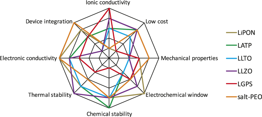
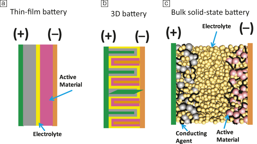
Many challenges remain to obtain solid-state batteries with performance metrics that exceed today’s lithium-ion batteries. First, the electrolyte material needs to meet an array of performance requirements (Figure 1). Current leading solid electrolyte materials all suffer from one or more shortcomings. High conductivity sulfide electrolytes tend to have poor oxidative chemical stability, while garnet-type materials are notoriously brittle. A common challenge, however, is the difficulty of device integration. Figure 2 shows three common configurations of solid-state batteries. A thin-film battery (Figure 2a) fabricated by vacuum deposition has been commercialized. Due to kinetic limitations, the thickness of each individual layer is limited, which restricts the maximum areal specific capacity (mAh•cm–2) of the system. In order to address this issue, three-dimensional batteries with interdigitated electrode structures have been proposed (Figure 2b).Reference Long, Dunn, Rolison and White10 However, this configuration demands a conformal electrolyte layer with complex contours. Alternatively, all-solid-state batteries are envisioned to have a structure similar to that of a lithium-ion battery. Composite electrodes (Figure 2c), composed of an active material, electrolyte, and conducting additives, are separated by a solid-electrolyte layer. This configuration dominates the research literature.Reference Trevey, Gilsdorf, Stoldt, Lee and Liu11 The main challenges include creating effective solid electrolyte/active material interfaces, as well as an overall reduction of the amount of solid electrolyte in the battery in order to achieve competitive energy densities.
Spider charts showing the array of performance metrics a solid-state electrolyte has to meet and a qualitative assessment of the leading materials. Note: LiPON, lithium phosphorus oxynitride; LATP, Li1+xAlxTi2–x(PO4)3; LLTO, Li0.05–3xLa0.5+xTiO3; LLZO, Li7La3Zr2O12; LGPS, Li10GeP2S12; salt-PEO, lithium salt-poly(ethylene oxide).
Typical envisioned structures for solid-state batteries: (a) thin-film battery, (b) 3D with interdigitated electrode/electrolyte structures, and (c) composite bulk battery.
Scientific understanding and challenges
Bulk and interfacial stability
Solid-state batteries are multiscale devices, both from a material as well as a system perspective, encompassing various physiochemical and electrochemical transport phenomena occurring at multiple length and time scales.Reference Pannala, Turner, Allu, Elwasif, Kalnaus, Simunovic, Kumar, Billings, Wang and Nanda12 For example, the secondary or aggregated transition-metal oxide cathode particles are in the size range of several microns, with primary particles being tens of nanometers or larger. Commercially available lithium foils are in the range of hundreds of microns thick, with the exception of evaporated Li films that can be much thinner. The solid electrolyte separator typically ranges in thickness between tens of microns up to the submillimeter regime.
The cell and stack size vary depending on the specific requirement and chemistry. The cell architecture has multiple material interfaces, including the Li-metal/solid electrolyte, solid electrolyte/cathode, and respective interfaces between the current collectors. Functioning solid-state batteries need to have high interfacial and electrochemical stability to enable high power and a larger voltage window.Reference Tian, Shi, Richards, Li, Kim, Bo and Ceder13,Reference Wu, Wang, Evans, Deng, Yang and Xiao14 This requires lower area-specific resistance both at the anode (Li-metal)/solid-electrolyte interface as well as the solid electrolyte/cathode interface. Further, the interface should be electrochemically (and chemically) stable at both anodic and cathodic limit to avoid formation of unfavorable passivation or reaction layers.
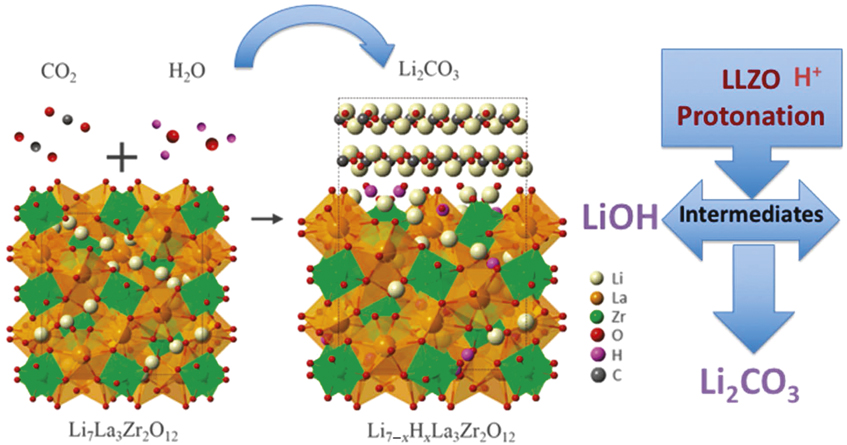
A wide set of interfacial reactions between the electrode and electrolyte phases are possible, and simple thermodynamic calculations are insufficient to determine the phases that may form, and how these phases will impact interfacial resistance. The reaction layers that form may either support or be detrimental to facile ionic conduction. They may occur quickly or only after a significant number of cycles.Reference Sharafi, Yu, Naguib, Lee, Ma, Meyer, Nanda, Chi, Siegel and Sakamoto15 They may be stable or grow over the life of the cell. Achieving and maintaining low interfacial resistance requires an understanding of the phases present on the surfaces of solid electrolytes, why these phases form, and how they evolve as a function of time, cycle number, and processing conditions. Studies suggest that high wettability between the solid electrolyte and electrode also ensures lower interface resistance.Reference Sharafi, Kazyak, Davis, Yu, Thompson, Siegel, Dasgupta and Sakamoto16 An ideal example is the Li metal/LLZO interface. LLZO surfaces when exposed to moist air readily form Li2CO3 via intermediates.Reference Sharafi, Yu, Naguib, Lee, Ma, Meyer, Nanda, Chi, Siegel and Sakamoto15,Reference Zhou, Li, Xin and Goodenough17 One of the preferred reaction pathways shown schematically in Figure 3 proceeds via a two-step process that involves protonation of LLZO (Li+/H+ exchange) and formation of LiOH as an intermediate product.Reference Sharafi, Yu, Naguib, Lee, Ma, Meyer, Nanda, Chi, Siegel and Sakamoto15 The two-step reaction can be described as:
 $${\rm{L}}{{\rm{i}}_{\rm{7}}}{\rm{L}}{{\rm{a}}_{\rm{3}}}{\rm{Z}}{{\rm{r}}_{\rm{2}}}{{\rm{O}}_{{\rm{12}}}} + {\rm{x}}{{\rm{H}}_{\rm{2}}}{\rm{O}} \to {\rm{L}}{{\rm{i}}_{{\rm{7 - }}x}}\,{{\rm{H}}_x}{\rm{L}}{{\rm{a}}_{\rm{3}}}{\rm{Z}}{{\rm{r}}_{\rm{2}}}{{\rm{O}}_{{\rm{12}}}} + {\rm{xLiOH;}}$$
 $${\rm{LiOH}} + {\rm{1/2C}}{{\rm{O}}_{\rm{2}}} \to {\rm{1/2L}}{{\rm{i}}_{\rm{2}}}{\rm{C}}{{\rm{O}}_{\rm{3}}} + {\rm{1/2}}{{\rm{H}}_{\rm{2}}}{\rm{O}}{\rm{.}}$$
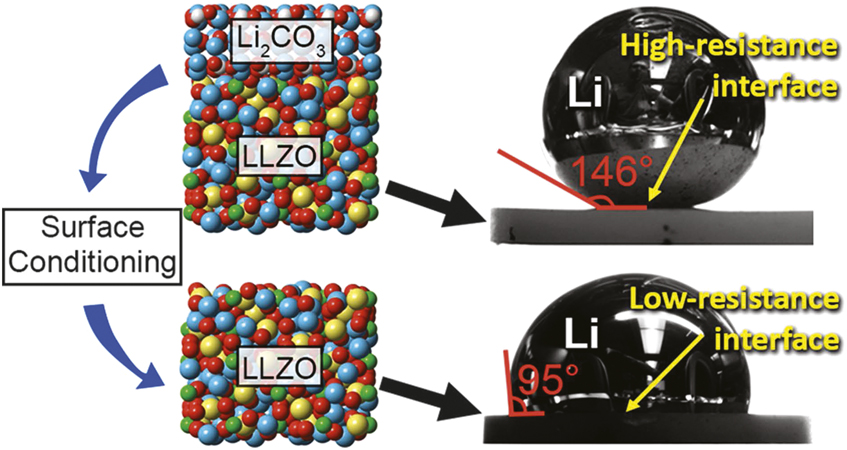
The contamination layer on LLZO is composed primarily of Li2CO3, LiOH, and adventitious carbon that contributes to the high interface resistance. Within experimental accuracy, depth profile x-ray photoelectron spectroscopy (XPS) studies on surface-contaminated LLZO show carbonate rich layers up to 40 nm followed by a buried LiOH layer. Recent studies have reported a surface-coating-free approach toward reducing the interfacial resistance by wet polishing followed by heat treatment under an inert atmosphere.Reference Sharafi, Kazyak, Davis, Yu, Thompson, Siegel, Dasgupta and Sakamoto16 An interfacial resistance as low as 2 ohm•cm was reported using this process. The removal of the contamination layer on LLZO also improved wetting of Li metal that led to a decrease in the interfacial resistance as demonstrated by contact angle measurements using molten Li-metal under various LLZO surface conditions (Figure 4).Reference Sharafi, Kazyak, Davis, Yu, Thompson, Siegel, Dasgupta and Sakamoto16 This example demonstrates the close interplay between surface composition (conditioning) and wettability toward achieving lower interface resistance.
One of the plausible reaction pathways for reaction layers formed on the Li7La3Zr2O12 (LLZO) surface that leads to an increase in area-specific resistance.Reference Sharafi, Yu, Naguib, Lee, Ma, Meyer, Nanda, Chi, Siegel and Sakamoto15
Interface wettability and its impact on interfacial resistance. Sessile drop experiment used to measure the contact angle of Li metal on Li2CO3 and Li7La3Zr2O12 (LLZO). Reprinted with permission from Reference Reference Sharafi, Kazyak, Davis, Yu, Thompson, Siegel, Dasgupta and Sakamoto16. © 2017 American Chemical Society.
In situ studies and characterization
Much progress has been made in developing in situ tools based on electrons, ions, and photons for directly observing the structural and chemical evolution of battery materials under dynamic operating conditions. Unlike ex situ studies that involve unexpected reactions due to the removal of the samples from their native and reactive environment, in situ electrochemical characterization mimics the true environment that a real battery experiences.Reference Huang, Zhong, Wang, Sullivan, Xu, Zhang, Mao, Hudak, Liu and Subramanian18,Reference Wang19 Essentially, solid-state battery configurations using solid electrolytes provide a convenient way for probing the structural and chemical evolution of electrode materials.
For the all-solid-state configuration, a device used for in situ studies may be related to the solid-state system as a battery itself or as a platform for in situ transmission electron microscopy (TEM) studies of a battery system. Brazier et al.Reference Brazier, Dupont, Dantras-Laffont, Kuwata, Kawamura and Tarascon20 developed the first cross-section preparation method for an all-solid-state Li-ion “nanobattery” for in situ TEM observations. The fundamental concept of this configuration is to use a focused ion beam (FIB) to make a “nanobattery” from an all-solid-state battery prepared by pulsed laser deposition (PLD). Using a similar configuration, Yamamoto et al.Reference Yamamoto, Iriyama, Asaka, Hirayama, Fujita, Fisher, Nonaka, Sugita and Ogumi21 observed in situ changes in electric potential in an all-solid-state Li-ion battery using electron holography. They mapped the two-dimensional potential distribution resulting from movement of lithium ions near the positive-electrode/electrolyte interface. Meng et al.Reference Meng, McGilvray, Yang, Gostovic, Wang, Zeng, Zhu and Graetz22 probed dynamic phenomena in an all-solid-state nanobattery based on imaging and electron energy-loss spectroscopy (EELS). Also Fawey et al.Reference Hammad Fawey, Chakravadhanula, Reddy, Rongeat, Scherer, Hahn, Fichtner and Kübel23 used an optimized FIB-based approach to prepare a micron-sized battery for in situ TEM studies in addition to starting from a powder-based all-solid-state fluoride-ion battery.
Imaging of a fabricated nanobattery inside a TEM allows for real-time atomic-scale observations of the dynamic evolution of the interface and internal structure of the electrode during operation of the battery with unprecedented spatial resolution. This allows for an atomic and nanoscale understanding of the mechanisms associated with the following: (1) Li-ion insertion and extraction mechanisms during the electrochemical cell operation; (2) the nature of the solid electrolyte interphase (SEI) layer between the electrode and the electrolyte, along with the movement of the SEI layer inside the electrode during charging/discharging; and (3) the change in the composition/structure of the SEI layer, along with the orientation/morphology of the nanostructured electrodes. Overall, the all-solid-state nanobattery provides a platform for coupled imaging, diffraction, and spectroscopy for comprehensive structural and chemical analysis of nanobatteries under typical battery operating conditions and offers the possibility of high spatial resolution imaging.
The behavior of functional interfaces is a crucial factor in the performance and safety of energy-storage and conversion devices. Indeed, solid electrode–solid electrolyte interfacial impedance is now considered the main limiting factor in all-solid-state batteries. Wang et al.Reference Wang, Santhanagopalan, Zhang, Wang, Xin, He, Li, Dudney and Meng24 presented a new approach to conducting in situ scanning transmission electron microscopy (STEM) coupled with EELS in order to uncover the unique interfacial phenomena related to Li-ion transport and its corresponding charge transfer. Their approach allowed quantitative spectroscopic characterization of a galvanostatically biased electrochemical system under in situ conditions. Using a LiCoO2/LiPON/Si thin-film battery, an unexpected structurally disordered interfacial layer between the LiCoO2 cathode and LiPON electrolyte was discovered to be inherent to this interface without cycling. During in situ charging, spectroscopic characterization revealed that this interfacial layer evolved to form highly oxidized Co ion species along with lithium-oxide and lithium-peroxide species. These findings suggest that the mechanism of interfacial impedance at the LiCoO2/LiPON interface is caused by chemical changes rather than space-charge effects. Insights gained from this technique will shed light on important challenges of interfaces in all-solid-state energy-storage and conversion systems and facilitate improved engineering of devices operated far from equilibrium.
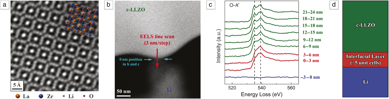
Ma et al.Reference Ma, Cheng, Yin, Luo, Sharafi, Sakamoto, Li, More, Dudney and Chi25 used in situ STEM and EELS (Figure 5) to reveal the formation of a Li-carbon–LLZO interface. They found that upon contact with Li metal, the LLZO surface is reduced, accompanied by the simultaneous implantation of Li+ and resulting in a tetragonal-like LLZO interphase that stabilizes at an extremely small thickness of around five unit cells. This interphase effectively prevented further interfacial reactions without compromising the ionic conductivity.
Formation of the c-LLZO-Li interfacial layer. (a) Scanning transmission electron microscope (STEM)-high-angle annular dark-field (HAADF) image showing the atomic structure of a pristine c-LLZO (crystalline-LLZO) specimen along the [001] zone axis. (b) STEM-HAADF image of c-LLZO in situ contacted with Li. (c) O-K edges obtained in the electron energy-loss spectroscopy (EELS) line scan described in (b). The two peaks characteristic of c-LLZO are indicated with dashed lines. (d) Schematic illustration of the interfacial behavior elucidated by the EELS line scanning analysis. Reprinted with permission from Reference Reference Ma, Cheng, Yin, Luo, Sharafi, Sakamoto, Li, More, Dudney and Chi25. © 2016 American Chemical Society. Note: LLZO, Li7La3Zr2O12.
One of the major concerns for in situ TEM studies of batteries is the electron-beam-induced artifact, typically beam-induced amorphization. To mitigate this problem, the electron-beam condition, especially the electron dose rate, needs to be carefully calibrated and controlled such that no obvious beam damage occurs. Cryo-electron microscopy techniques, mostly developed for biological science, can also be used to mitigate the beam effect, which has been demonstrated for the case of probing into the SEI layer.Reference Wang, Zhang, Alvarado, Wang, Sina, Lu, Bouwer, Xu, Xiao and Zhang26,Reference Li, Li, Pei, Yan, Sun, Wu, Joubert, Chin, Koh and Yu27 Ideally it would be expected that an integrated device will be developed that will allow control of both temperature and cycling of the battery, equivalent to a same platform combination of in situ and cryo-microscopy.
In this issue
This issue focuses on recent developments in solid ion conductors and the various surface and interfacial challenges that need to be addressed for enabling solid-state batteries. In their article in the issue, Ceder et al.Reference Ceder, Ong and Wang28 discuss first-principles modeling of ionic conductivity and interfacial reactivity to understand the intrinsic performance and limitations of solid electrolytes. Using ab initio molecular dynamics, ionic conductivity can be predicted with reasonable accuracy. Thermodynamic models for electrochemical stability and interfacial reactivity have been used to establish the intrinsic voltage limits at which solid electrolytes can operate in solid-state batteries.
The DudneyReference Dudney29 article highlights the current status of efforts to stabilize the Li-metal anode, including strategies for mitigation of Li-metal dendrite growth and processing methods. Hallinan et al.Reference Hallian, Villaluenga and Balsara30 report on the current status of polymer electrolytes, including compositions and the mechanistic understanding of ion transport mechanisms in composite electrolytes. Wynn et al.Reference Wynn, Lee, Banerjee and Meng31 provide a comprehensive review of in situ and in operando methodologies that are currently under development for solid-state interfaces and offer the potential to describe the dynamic interfacial processes that serve as performance bottlenecks for solid-state batteries. Finally, Hao et al.Reference Hao, Han, Liang, Wang and Yao32 provide their perspective on device architecture of solid-state batteries and discuss various fabrication approaches for achieving intimate interparticle and interlayer contact that are critical for solid-state battery performance.
Acknowledgments
Research supported by the Assistant Secretary for Energy Efficiency and Renewable Energy, Office of Vehicle Technologies of the US Department of Energy (DOE) through the Advanced Battery Materials Research (BMR) Program. J.N. thanks G. Yang and E. Self for technical discussions. C.W. is grateful for the support of the William R. Wiley Environmental Molecular Sciences Laboratory, a national scientific user facility sponsored by the DOE’s Office of Biological and Environmental Research and located at Pacific Northwest National Laboratory.

Jagjit Nanda is a team lead and senior staff scientist in the Materials Science and Technology Division of Oak Ridge National Laboratory, working in the area of high-capacity energy-storage materials, interfaces, and energy systems. He received his PhD degree in solid-state chemistry and materials science from the Indian Institute of Science, Bangalore, in 2000, followed by a postdoctoral fellowship at Stanford University and a research associateship at Los Alamos National Laboratory. Prior to joining Oak Ridge in 2009, he was the technical expert at the Research and Advanced Engineering Center, Ford Motor Company, leading R&D projects in lithium-ion battery materials and nanomaterials for energy application. He has published more than 150 publications and is an active member of several scientific societies. Nanda can be reached by email at nandaj@ornl.gov.

Chongmin Wang is a chief scientist at the Environmental Molecular Sciences Laboratory, Pacific Northwest National Laboratory (PNNL). He received his BSc and MSc degrees in physics from Lanzhou University, China, and his PhD degree in materials science and engineering from the University of Leeds, UK. Before joining PNNL, he worked at the Max Planck Institute for Metals Research, Germany; National Institute for Materials Science, Japan; and Lehigh University. His research interests include state-of-the-art S/TEM imaging and spectroscopy and their application to materials challenges, especially in situ S/TEM and energy materials. He is the recipient of the MRS Innovation in Materials Characterization Award, JMR Paper of the Year Award, Microscopy Today Innovation Award, Rowland Snow Award (The American Ceramic Society), an R&D100 Award, Outstanding Invention Award (Japan), and PNNL Directors Award for Exceptional Scientific Achievement. He is a Fellow of MRS. Wang can be reached by email at chongmin.wang@pnnl.gov.

Ping Liu is an associate professor of nanoengineering at the University of California, San Diego. He received his BS, MS, and PhD degrees in chemistry from Fudan University, China, and was a postdoctoral fellow at the National Renewable Energy Laboratory. Prior to his current appointment, he was a program director at the Advanced Research Projects Agency-Energy and a manager at HRL Laboratories. His research interests include materials and architectures for rechargeable batteries, as well as nanomaterials synthesis and characterization. Liu can be reached by email at piliu@ucsd.edu.


