Introduction
In recent years, there has been extensive work on the hierarchical classification of many groups of minerals, and we now have a reasonable idea of the principal factors that should be involved in such classifications. Hawthorne (Reference Hawthorne2014) formalised the idea of a Structure Hierarchy, briefly reviewed several groups of minerals that have been so organised, and showed how such structure hierarchies (1) form a basis for understanding the factors affecting the chemical composition and bond topology of minerals, and (2) provide insight into mechanisms of crystallisation. Structure hierarchies have been developed for the following groups of minerals: phosphates, arsenates and vanadates (Kostov and Breskovska, Reference Kostov and Breskovska1989), phosphates (Hawthorne, Reference Hawthorne1998; Huminicki and Hawthorne, Reference Huminicki, Hawthorne, Kohn, Rakovan and Hughes2002a), arsenates (Majzlan et al., Reference Majzlan, Drahota, Filippi, Bowell, Alpers, Jamieson, Nordstrom and Majzlan2014), vanadium bronzes (Evans and Hughes, Reference Evans and Hughes1990), sulfates (Sabelli and Trosti-Ferroni, Reference Sabelli and Trosti-Ferroni1985; Hawthorne et al., Reference Hawthorne, Krivovichev, Burns, Alpers, Jambor and Nordstrom2000), tellurium oxycompounds (Christy et al., Reference Christy, Mills and Kampf2016), uranyl oxysalts (Burns, Reference Burns, Burns and Finch1999, Reference Burns2005, Burns et al., Reference Burns, Miller and Ewing1996), borates (Burns et al., Reference Burns, Grice and Hawthorne1995; Hawthorne et al., Reference Hawthorne, Burns, Grice, Anovitz and Grew1996; Grice et al., Reference Grice, Burns and Hawthorne1999), aluminofluoride minerals (Hawthorne, Reference Hawthorne1984), and structures based on anion-centred polyhedra (Filatov et al., Reference Filatov, Semenova and Vergasova1992; Krivovichev, Reference Krivovichev2008, Reference Krivovichev2009; Krivovichev and Filatov, Reference Krivovichev and Filatov1999a,Reference Krivovichev and Filatovb; Krivovichev et al., Reference Krivovichev, Filatov and Semenova1998, Reference Krivovichev, Mentré, Siidra, Colmont and Filatov2013). The surprising omission from this list of mineral groups is the silicate group (sensu lato), as these minerals are central to petrological processes in the crust and mantle of the Earth.
The basis of a structure hierarchy for common silicate minerals was developed by Matchatski (Reference Matchatski1928) and Bragg (Reference Bragg1930), the classification that we still use today: neso (ortho-), soro-, cyclo- (ring-), ino- (chain-), phyllo- (sheet-) and tecto- (framework) silicates. The other major development was that of Belov (Reference Belov1958, Reference Belov1961) who introduced the ‘Second Chapter’ of silicate crystal-chemistry that organises silicates of large alkali and alkaline-earth cations (e.g. Ca2+, Ba2+ and Sr2+) and focuses on the linkage between different coordination polyhedra in a wide variety of minerals in terms of ‘mixed frameworks’ (Voronkov et al., Reference Voronkov, Zhdanova and Pyatenko1974, Reference Voronkov, Ilyukhin and Belov1975; Sandomirskii and Belov, Reference Sandomirski and Belov1984). Zoltai (Reference Zoltai1960) included other tetrahedrally coordinated oxyanions into the Bragg classification, focusing attention on the factors that affect the relative linkage of silicate, beryllate and borate groups in extended polymerisations. Several other classification criteria, based on the topological and geometrical characteristics of the silicate and aluminosilicate linkages, were introduced by Liebau (Reference Liebau1985). The number of silicate minerals make the development of a coherent and detailed structure hierarchy for silicates a rather intimidating task. However, it is time that this was done; an important topic should not be ignored just because it is a lot of work.
We will deal with the large number of minerals by dividing the silicate minerals into four categories and addressing these categories separately: (1) Cluster silicates: these are silicates that do not have any infinitely extended spatial polymerisation of tetrahedra (i.e. neso-, soro- and cyclosilicates); (2) chain-ribbon silicates: silicates with one direction of infinite polymerisation of tetrahedra (inosilicates); (3) sheet silicates: silicates with two directions of infinite polymerisation of tetrahedra (phyllosilicates); and (4) framework silicates: silicates with three directions of infinite polymerisation of tetrahedra (tectosilicates). Here, we examine the structure hierarchy of sheet-silicate minerals. Hawthorne (Reference Hawthorne2015a) discussed the structures of sheet silicates in terms of n-connected plane nets (2 < n ≤ 4), showed how such nets can be combined with various oikodoméic operations (topological building operations) to generate sheet-silicate (sensu lato) structures, and went on to develop formula-generating and structure-generating functions for such nets and their associated oikodoméic operations. Here, we examine observed sheet-silicate structures, see how their chemical compositions and structures may be generated from n-connected plane nets and associated building operations, and arrange them into a hierarchy based on increasing degree of connectivity of their silicate structural-unit.
Where we refer to a ‘silicate sheet’, that sheet must contain Si4+ but also may contain any other tetrahedrally coordinated cation such as Ti4+, Al3+, Fe3+, B3+, P5+, As5+, V5+, Mg2+, Fe2+, Mn2+, Zn2+ and possibly S6+, Cr6+ and Li+. We will refer to a tetrahedron by its central cation: thus ‘Si4+ tetrahedron’ represents an (Si4+![]() ${\rm O}_4^{{\rm 2\ndash}} $)4– tetrahedron, and ‘T tetrahedron’ represents a (TO4)n– tetrahedron, where T is one or more unspecified tetrahedrally coordinated cations. With such a wide compositional range of minerals and large number of structures, the colour scheme for the various polyhedra and nets is somewhat complicated; this is listed in Table 1, and we will not refer to this scheme in each figure caption. In some cases, other aspects of a structure need to be emphasised by using the colours of Table 1 to indicate other features (e.g. 2-connected vertices in a net); where this is done, the colour scheme will be noted in the figure caption. Also, mineral names are written in bold font to facilitate comparison of different structures throughout the text. Bond valences were calculated with the parameters of Gagné and Hawthorne (Reference Gagné and Hawthorne2015). In the tables listing mineral species, we have attempted where possible to write each mineral as the principal end-member formula (Hawthorne, Reference Hawthorne2002) as this simplifies the connections between mineral composition and bond topology, and also facilitates comparison of different minerals. Here, we follow the idea of Binary Structural Representation (Hawthorne and Schindler, Reference Hawthorne and Schindler2008) whereby structures are partitioned into a strongly bonded structural unit and a weakly bonded ‘interstitial complex’. In the tables that follow, the structural unit (i.e. the silicate part of the structure) is written in square brackets and bold font, except where there is some question as to the formula of the structural unit (which may be the case where there is significant disorder of the constituents of that structural unit), and the interstitial complex (the weakly bonded constituents that link the structural unit into a complete crystal structure) is shown in normal font. References to specific minerals are made in the tables (not the text) except where dealing with more general topics.
${\rm O}_4^{{\rm 2\ndash}} $)4– tetrahedron, and ‘T tetrahedron’ represents a (TO4)n– tetrahedron, where T is one or more unspecified tetrahedrally coordinated cations. With such a wide compositional range of minerals and large number of structures, the colour scheme for the various polyhedra and nets is somewhat complicated; this is listed in Table 1, and we will not refer to this scheme in each figure caption. In some cases, other aspects of a structure need to be emphasised by using the colours of Table 1 to indicate other features (e.g. 2-connected vertices in a net); where this is done, the colour scheme will be noted in the figure caption. Also, mineral names are written in bold font to facilitate comparison of different structures throughout the text. Bond valences were calculated with the parameters of Gagné and Hawthorne (Reference Gagné and Hawthorne2015). In the tables listing mineral species, we have attempted where possible to write each mineral as the principal end-member formula (Hawthorne, Reference Hawthorne2002) as this simplifies the connections between mineral composition and bond topology, and also facilitates comparison of different minerals. Here, we follow the idea of Binary Structural Representation (Hawthorne and Schindler, Reference Hawthorne and Schindler2008) whereby structures are partitioned into a strongly bonded structural unit and a weakly bonded ‘interstitial complex’. In the tables that follow, the structural unit (i.e. the silicate part of the structure) is written in square brackets and bold font, except where there is some question as to the formula of the structural unit (which may be the case where there is significant disorder of the constituents of that structural unit), and the interstitial complex (the weakly bonded constituents that link the structural unit into a complete crystal structure) is shown in normal font. References to specific minerals are made in the tables (not the text) except where dealing with more general topics.
Legend for Figures.
Nets and sheet-silicate structures
Nets are used widely to describe crystal structures, and have been particularly important to the description and theoretical analysis of silicate structures (e.g. Wells, Reference Wells1962, Reference Wells1977; Smith, Reference Smith1977, Reference Smith1978, Reference Smith1988; Hawthorne and Smith, Reference Hawthorne and Smith1986a,Reference Hawthorne and Smithb, Reference Hawthorne and Smith1988; Krivovichev, Reference Krivovichev2008, Reference Krivovichev2009). Hawthorne (Reference Hawthorne2015a) described how nets may be used to theoretically derive possible atomic arrangements of the silicate components of minerals. With regard to the present work on sheet-silicate minerals, the salient issues are dealt with in the following sections.
Nets as representations of sheets of tetrahedra
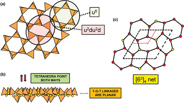
Planar 3-connected nets may be used as compact representations of the connectivity of silicate sheets that have the stoichiometry [T2nO5n] where n = 1–24; an example is shown in Fig. 1. In the sheet of corner-linked tetrahedra (Fig. 1a), all tetrahedra link to three other tetrahedra, i.e. they are 3-connected. In Fig. 1b, the vertices of the net represent the tetrahedra and the edges of the net represent the linkage between the tetrahedra. All tetrahedra in Fig. 1a have their apical vertices pointing in the same direction (up in terms of the viewer), and the tetrahedra of the six-membered rings are designated as being in the u6 arrangement (Hawthorne, Reference Hawthorne2015a); note that such an arrangement is not inherent in Fig. 1b unless we specifically colour the vertices to indicate u and d behaviour of the analogous tetrahedra. Also emphasised in Fig. 1b is the three-connected nature of the net vertices and the unit cell of the net (which contains two vertices and five edges: [Si2O5]). Common 3-connected nets are listed in Table 2 and illustrated in Fig. 2. Nearly all of these nets correspond to known structures of silicate minerals. There are an infinite number of other 3-connected plane nets, but these need not be considered until structural analogues are discovered or suspected. There are certain geometrical variations in single-layer sheets of tetrahedra that do not change the linkage of the corresponding net, and hence stoichiometry is conserved by these variations (Hawthorne, Reference Hawthorne2015a). However, these variations play an important role in the formation of more complicated sheets, and also are key features in linkage between the sheet and the interstitial complex.
(a) The mica sheet of tetrahedra; (b) the 63 net with its unit cell shown by dotted black lines; and (c) the mica sheet showing that the tetrahedra all point in the same direction, and that the O(br) anions (shown as yellow circles) are planar. Net vertices: red circles; net edges: green lines. Modified from Hawthorne (Reference Hawthorne2015a).
The simpler 3-connected plane nets: (a) the 63 net; (b) the 4.82 net; (c) the 3.122 net; (d) the 4.6.12 net; (e) the (4.6.8)2(6.82)1 net; (f) the (52.8)1(5.82)1 net; (g) the (4.6.10)4(62.10)1 net; (h) the (3.82)1(6.82)1 net; (i) (52.8)1(5.62)1(5.6.8)2(62.8)1 net; and (j) the (5.6.7)4(5.72)1(62.7)1 net; the unit cell of each net is shown by dotted lines.
Simple 3-connected plane nets.
Planar and folded sheets of tetrahedra
In Figs 1 and 3, all O(bridging) [ = O(br)] anions are shown as yellow circles; note that in Fig. 1, the O(br)] anions lie in the plane of the net. Figure 3a shows the sheet in sanbornite with tetrahedra at the vertices of a 63 net; the view from one direction shows that the O(br) anions are very non-planar whereas the view from the orthogonal direction shows that the O(br) anions are quasi-planar. The arrangement of tetrahedra in cuprorivaite (Fig. 3b) shows a sheet with tetrahedra at the vertices of a 4.82 net. The view of the sheet from both horizontal directions shows that the O(br) anions are very non-planar in each direction, and the sheet in Fig. 3b is repetitively folded about (fold) axes parallel to both viewing directions orthogonal to the sheet. Here, we will not consider linkage between sheets and extra-sheet species, but note that geometrically-planar sheets tend to link to units involving edge-sharing octahedra coordinating medium-sized di- and trivalent cations whereas folded sheets tend to link to polymerisations of more highly coordinated cation polyhedra.
Folded sheets of tetrahedra; (a) sanbornite: the 63 silicate sheet and views in the plane of the sheet, showing folding in one direction; and (b) cuprorivaite: 4.82 silicate sheet and views in the plane of the sheet, showing folding in two directions. Yellow circles represent O(br) anions.
The relative orientation of tetrahedra in sheets of tetrahedra
In the net of Fig. 1b, each vertex represents a tetrahedron. However, a vertex has no orientation relative to the plane of the net, which is not the case for a tetrahedron. The apical ([1]-coordinated) anion of a 3-connected tetrahedron may lie on one side of the sheet or the other. Thus tetrahedra in a sheet may all point in the same direction or the tetrahedra may point in different directions. In Fig. 1, the tetrahedra all point in one direction (see Fig. 1c) which we designate as u (up towards the reader). Figures 4a,b show tetrahedra at the vertices of the 63 net, and both Figs 4a and 4b show that the tetrahedra point in both directions, u and d (down), relative to the plane of the sheet. There are two distinct six-membered rings in Fig. 4a; in one ring, all tetrahedra point in the same direction: (u6); in the other ring, tetrahedra point in different directions: four point up (in the same direction as the tetrahedra in the first ring) and two point down (in the opposite direction to the tetrahedra of the first ring), and the sequence around the ring gives the symbol (u2du2d) (Fig. 4a). Thus the attitude of the tetrahedra in a sheet may be represented by these (u–d) strings. For a single-layer sheet, the designation of a specific tetrahedron as u (or d) is arbitrary. In single-layer sheets, we adopt the convention whereby the direction of the larger number of tetrahedra is defined as u. For a double-layer sheet, tetrahedra of the upper parent-layer sheet that point away from the plane containing the oikodoméic operation are defined as u.
The occurrence of u–d tetrahedra in the structure of gyrolite; (a) shows the tetrahedra at the vertices of a 63 net with u and d tetrahedra indicated; (b) shows a cross-sectional view of the sheet, showing the tetrahedra pointing both ways and the planar nature of the O(br) anions (shown as yellow circles); and (c) the net of vertices in which red circles represent u tetrahedra and the yellow circles represent d tetrahedra; the unit cell is shown by heavy broken lines and the unit cell of the parent 63 net (cf. Fig. 2a) is shown by dotted red lines.
The apical anions of the u and d tetrahedra of Fig. 4 lie out of the plane of the T–O–T linkages. However, this is not necessarily the case. Figure 5a shows the sheet of tetrahedra in ferronordite-(Ce). As is apparent in the cross-section of a narrow slice of the sheet (Fig. 5b), the presence of tetrahedra with their edges in the upper and lower surfaces of the sheet allows the u and d tetrahedra not to project above or below the sheet itself, and produces a new type of tetrahedron which we will denote as o. Although this type of arrangement is more common in sheets involving 4-connected tetrahedra, as in ferronordite-(Ce), it does occur in sheets with only 3-connected tetrahedra (as in the minerals of the gadolinite supergroup (Bačík, Reference Bačík, Miyawaki, Atencio, Cámara and Fridrichová2017), see below).
The sheet of 3-connected (orange) and 4-connected (violet) tetrahedra in ferronordite-(Ce): (a) plan view of the sheet; and (b) view of a thin ribbon (between the dashed lines of Fig. 5a) of the sheet in the plane of the sheet.
We also need to define the directions u and d relative to the rest of the structure. As noted below, silicate sheets may have more than one layer of tetrahedra (Liebau, Reference Liebau1985; Hawthorne, Reference Hawthorne2015a). In double-layer silicate structures, we will define d tetrahedra of the upper layer as linking to tetrahedra in the lower layer, and hence u tetrahedra link to the rest of the structure. In single-layer silicates, we do not have this internal definition of direction. In this case, we generally define the majority of tetrahedra as u and the minority as d, and hence the designation of u and d in these cases is more arbitrary.
In order to represent the information of the u and d directions of tetrahedra, it is necessary to use a slightly more complicated net nomenclature. The nets in Fig. 2 show the unit cells in dotted lines. Consider the net 63 (Fig. 2a) and its associated silicate sheet (Fig. 1a); these have a unit cell that contains two vertices/tetrahedra. Consider the silicate sheet in Fig. 4a; the topology of this sheet is based on the 63 net but the unit cell has to be larger in order to represent the u and d nature of the tetrahedra; this is equivalent to colouring the vertices of the net different colours according to the u or d nature of the tetrahedron corresponding to that vertex. It is obvious from Fig. 4a that the unit cell of the 63 net in Fig. 2 is not adequate to do this. The net corresponding to the sheet in Fig. 4a is shown in Fig. 4c with the u tetrahedra shown as red vertices and the d tetrahedra shown as yellow vertices. The corresponding unit-cell in Fig. 4c is shown as heavy broken lines, and part of the unit cell of the parent 63 net is shown as dotted red lines. It is apparent that the true unit-cell is four times the size of the parent unit-cell. We wish to retain the number of constituent vertices in the net symbol, and hence this number will need to be contained in the net. We may do this by enclosing the reduced net symbol. i.e. the set of vertices with any common factor removed from the stoichiometric coefficients and placed outside a pair of square brackets. Thus the nets in Figs 2a–d are expressed as [63]2, [4.82]4, [3.122]6 and [4.6.12]12. For the net in Fig. 2e, there are six vertices in the unit cell and there are two distinct vertices, (4.6.8) and (6.82) in the ratio 2:1; hence the net symbol is [(4.6.8)2(6.82)1]2 such that the product of the sum of the stoichiometric coefficients within the square brackets and the subscript outside the square brackets is equal to the number of vertices in the unit cell of the net: (2 + 1) x 2 = 6 (Fig. 2e). We note that this approach is only a notation for the recording the u and d directions of tetrahedra. A more rigorous method of describing u and d tetrahedra based on orientational matrices was developed by Krivovichev and Burns (Reference Krivovichev and Burns2003) and amplified by Krivovichev (Reference Krivovichev2009). The former has the advantage of simplicity whereas the latter has potential for combining with structure-generating functions (Hawthorne, Reference Hawthorne2015a) to rigorously derive all possible sheet arrangements.
Multi-layer tetrahedron-sheets and oikodoméic operations
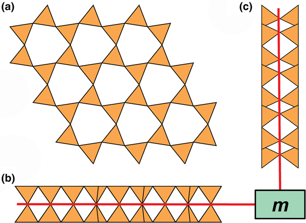
Liebau (Reference Liebau1985) divided sheet silicates into two types: single-layer sheets and double-layer sheets. In Fig. 6a, tetrahedra lie at the vertices of a 63 net, and all tetrahedra have their apical vertices concealed below the plane of the figure. However, viewing perpendicular to the sheet (Figs. 6b,c) shows that there is another single-layer of tetrahedra directly underlying the upper net, and the lower tetrahedra have their apical vertices pointing upward. The sheet of Fig. 6 is a double-layer sheet with a mirror (or pseudo-mirror) plane relating the upper and lower layers of the sheet.
A double-layer silicate sheet; (a) d tetrahedra at the vertices of a 63 net; (b) and (c) views of the sheet parallel to the plane of the sheet, showing that the double sheet has a lower-layer component in which u tetrahedra occur at the vertices of a 63 net; the upper and lower payers are related by a mirror (or pseudo-mirror) plane shown by the red line and labelled m.
Hawthorne (Reference Hawthorne2015a) introduced a series of topological operations that change the bond topology of a parent net. Stoichiometry is not conserved but changes systematically in accord with the particular operation, giving rise to more complicated nets that can represent more complicated sheet structures. These operations are designated as oikodoméic operations as they involve the act of building new structural arrangements (from the Greek word oikodomé: the act of building). There are three classes of oikodoméic operations that can affect nets or sheets of connected tetrahedra: [1] insertion, whereby vertices of different connectedness are inserted into the edges of a parent net; [2,3] replication operations, whereby a single-layer sheet is replicated, reoriented and linked to the original single-layer sheet to produce a double-layer sheet of tetrahedra. Class-2 oikodoméic operations replicate the parent layer about apical anions of d tetrahedra (Figs 7a,b), whereas class-3 operations replicate the parent layer about the central cations of d tetrahedra (Figs 7c,d). How do these oikodoméic operations differ from symmetry operators? A symmetry element is part of the symmetry of an already existing arrangement, and the corresponding symmetry operation describes the transformation of part of the arrangement to geometrical congruence with another part of the arrangement, whereas oikodoméic operations generate arrangements with the corresponding (topological) symmetry from a simpler parent arrangement of tetrahedra.
Oikodoméic operations replicating and reorienting the upper single-layer tetrahedra from above the plane of the operation to below the plane of the operation; (a) the mirror operation acting though apical anions of the upper single-layer parent sheet; (b) the two-fold rotation operation acting though apical anions of the upper single-layer parent sheet; (c) the mirror operation though the central T cations of tetrahedra shared between the upper and lower single-layer sheets; and (d) the two-fold rotation operation acting though the central T cations of tetrahedra shared between the upper and lower single-layer sheets.
Recently, three silicate minerals have been described as triple-layer: günterblassite, (K,Ca)3–xFe[(Si,Al)13O25(OH,O)4](H2O)7 (Chukanov et al., Reference Chukanov, Rastsvetaeva, Aksenov, Pekov, Zubkova, Britvin, Belakovskiy, Schüller and Ternes2012a); umbrianite, K7Na2Ca2[Al3Si10O29]F2Cl2 (Sharygin et al., Reference Sharygin, Pekov, Zubkova, Khomyakov, Stoppa and Pushcharovsky2013); and hillesheimite, (K,Ca,□)2(Mg,Fe,Ca,□)2[(Si,Al)13O23(OH)6](OH)(H2O)8 (Chukanov et al., Reference Chukanov, Rastsvetaeva, Aksenov, Pekov, Zubkova, Britvin, Belakovskiy, Schüller and Ternes2013). These also may be generated from parent sheets by oikodoméic replication operations.
Interstitial constituents
The idea of Binary Structure Representation (e.g. Hawthorne and Schindler, Reference Hawthorne and Schindler2008) considers structures as being partitioned into two parts, a strongly bonded (usually anionic) Structural Unit and a (usually cationic) Interstitial Complex that binds the structural units into a continuous structure. The development of structure hierarchies focuses on the structural units, but the interstitial complex is also of great interest as the Principle of Correspondence of Lewis-acidity – Lewis-basicity (Hawthorne, Reference Hawthorne2012a, Reference Hawthorne2015b) allows analysis of the factors that control the chemical compositions and aspects of the structural arrangements of both the structural unit and the interstitial complex (e.g. Hawthorne and Schindler, Reference Hawthorne and Schindler2008, Schindler and Hawthorne, Reference Schindler and Hawthorne2001a,Reference Schindler and Hawthorneb,Reference Schindler and Hawthornec, Reference Schindler and Hawthorne2004, Reference Schindler and Hawthorne2008; Schindler et al., Reference Schindler, Hawthorne and Baur2000, Reference Schindler, Huminicki and Hawthorne2006). As we plan to do this as part of our future work on sheet-silicate minerals, we shall describe the stereochemistry of the interstitial complex, i.e. the coordination of the cation constituents and (H2O), in particular the role of (H2O) as Transformer (H2O)t, Non-Transformer (H2O)n, Inverse-Transformer (H2O)i and solely hydrogen-bonded (H2O)z groups (Hawthorne, Reference Hawthorne1992; Hawthorne and Schindler, Reference Hawthorne and Schindler2008; Hawthorne and Sokolova, Reference Hawthorne and Sokolova2012) unless the details are obscured by positional disorder.
Structure hierarchy
In a hierarchical classification, it is general practice to arrange the structural units in terms of increasing connectivity. Connectivity is inversely correlated with T:O ratio, and planar 3-connected nets have the stoichiometry [T2nO5n]. Insertion of 2-connected vertices will increase the T:O ratio, whereas insertion of 4-connected vertices and generation of double-layer sheets via oikodoméic replication operations will decrease the T:O ratio (i.e. they increase the connectivity of the tetrahedra). For those structures with the same T:O ratio, we will arrange the structures in order of increasing complication of the nets on which they are based. We will start with single-layer 3-connected nets with inserted 2-connected vertices, as these structures have T:O ratios greater n = 2.5 (and the lowest connectivity of the sheet-silicate structures).
Single-layer sheets: 3-connected nets with inserted 2-connected vertices
Single 2-connected vertices
Figure 8 shows three inserted plane nets derived from the 63 net. In Fig. 8a, 2-connected vertices have been inserted into all edges of the 63 net (a class-1 oikodoméic operation), maintaining the original translational symmetry. The original six-membered rings have the u–d sequence (ududud) and become twelve-membered rings on insertion of the 2-connected tetrahedra; the resulting net is (122)3(123)2. Figure 8b shows the net of the silicate sheet in zeophyllite (Table 3) and Fig. 8c shows the corresponding silicate sheet in zeophyllite. The geometrical symmetry of the archetype 63 net is preserved and the unit cell is the same in both nets (cf. Figs 1b and 8b). The interstitial complex consists of three distinct Ca2+ ions with coordination numbers [6] (= six O2–), [8] (= four O2– and four F–) and [8] (= four O2–, three F– and one (H2O)t group). The O(1) anion is bonded to Si(1) and accepts three hydrogen bonds from the (H2O)t group, and one F– ion accepts a hydrogen bond from the (H2O) group.
Nets and corresponding structures derived from the 3-connected plane net 63 by insertion of 2-connected vertices between 3-connected vertices; (a) the (122)3(123)2 net; (b) the [(122)3(123)2]1 net in the structure of zeophyllite; (c) the sheet of tetrahedra in zeophyllite; (d) the (102)4(103)4 net; (e) the [(102)4(103)4]1 net in the structure of tumchaite; (f) the sheet of tetrahedra in tumchaite; (g) the (82)4(83)8 net; (h) the [(82)4(83)8]1 net in the structure of kvanefjeldite; and (i) the sheet of tetrahedra in kvanefjeldite. Yellow circles: two-connected vertices.
Single-layer sheet-silicates based on 3-connected nets with inserted 2-connected vertices.
References: (1) Merlino (Reference Merlino1972); (2) Chukanov et al. (Reference Chukanov, Yakubovich, Pekov, Belakovsky and Massa2008), Yakubovich et al. (Reference Yakubovich, Massa and Chukanov2008); (3) Kolitsch et al. (Reference Kolitsch, Merlino and Holstam2012); (4) Subbotin et al. (Reference Subbotin, Merlino, Pushcharovsky, Pakhomovsky, Ferro, Bodanova, Vloshin, Sorokhtina and Zubkova2000); (5) Johnsen et al. (Reference Johnsen, Leonardsen, Fälth and Annehed1983), Petersen et al. (Reference Petersen, Johnsen, Leonardsen and Rønsbo1984); and (6) Grew et al. (Reference Grew, Peacor, Rouse, Yates, Su and Marquez1996).
*The u–d arrangement refers to the parent 63 net.
**P = planar; 1F = folded in one direction.
The sheets in britvinite and molybdophyllite (Table 3) are also based on the (122)3(123)2 net, but the u–d sequence in the parent 63 sheet is (u6) for both minerals. The interstitial complex in britvinite consists of twenty distinct Pb2+ ions with coordination numbers from [6] to [10] and coordinating anions O2–, (OH)–, F– and Cl–. The interstitial complex in molybdophyllite consists of four distinct Pb2+ ions with coordination numbers from [6] to [9] and six distinct Mg2+ ions each of which is coordinated by six O2– ions.
In Fig. 8d, 2-connected vertices have been inserted into two-thirds of the edges of the 63 net, again maintaining the original translational symmetry. The original six-membered rings become ten-membered rings and the resulting net is (102)4(103)4. Figure 8e shows the net of the silicate sheet in tumchaite (Table 3) and Fig. 8f shows the corresponding silicate sheet. The net corresponding to the sheet of tetrahedra is strongly geometrically distorted (Fig. 8e), but is [(102)4(103)4]1 and topologically identical to the ideal inserted net in Fig. 8d. This geometrical distortion causes a doubling in the size of the unit cell (Fig. 8e) relative to that of the parent net (Fig. 1b). The interstitial complex in tumchaite consists of one distinct Zr4+ ion with coordination number [6] and one distinct Na+ ion which is coordinated by five O2– ions and two (H2O) groups.
In Fig. 8g, 2-connected vertices are inserted into one-third of the edges of the 63 net, maintaining the original translational symmetry. As noted by Hawthorne (Reference Hawthorne2015a), the resulting arrangement is very different from those of the nets in Figs 8a and 8d. The six-membered ring in Fig. 8g does not have trans symmetry and hence the unit cell must span more than one single six-membered ring. As a result, the unit cell must be larger than that of the parent net, and a further doubling is caused by the geometrical distortion of the sheet. Figure 8h shows the net of the silicate sheet in kvanefjeldite (Table 3) and Fig. 8i shows the corresponding silicate sheet. The interstitial complex in kvanefjeldite consists of one distinct Ca2+ ion with coordination number [6] and two distinct Na+ ions both of which are coordinated by seven O2– ions.
Pairs of 2-connected vertices
In Fig. 9, pairs of 2-connected vertices have been inserted into one-third of the edges of the 63 net, maintaining the original translational symmetry. The resultant net is (142)6(143)2, and in the corresponding sheet of tetrahedra in hyttsjöite (Fig. 9a; Table 3), the 2-connected tetrahedra are coloured yellow. The sheet is quite corrugated and also shows considerable geometrical distortion from a geometrically holosymmetric 63 net. The structure of hyttsjöite also contains a discontinuous layer of tetrahedra (Fig. 9b) which is linked into a continuous layer by pairs of short bonds involving lone-pair-stereoactive Pb2+, and this arrangement accounts for the very high Si:O ratio: 1:3.00 (Table 3). The interstitial complex in hyttsjöite is quite complicated. It consists of three distinct Pb2+ ions coordinated solely by O2– with coordination numbers [8], [8] and [6], respectively, one Ba2+ coordinated by twelve O2– ions, three distinct Ca2+ ions with coordination numbers [6] (= six O2–) and [9] (= eight O2– ions and one (H2O) group, and nine O2– ions, respectively), one Fe3+ and one Mn2+ each coordinated by six O2– ions.
Net and corresponding structure derived from the 3-connected plane net 63 by insertion of pairs of 2-connected vertices between all 3-connected vertices; (a) the (142)6(143)2 net and the sheet of tetrahedra in hyttsjöite; and (b) the partly disconnected layer of tetrahedra in hyttsjöite, showing short Pb2+–O bonds that link it into a sheet. Yellow circles: two-connected vertices; yellow tetrahedra: two-connected tetrahedra; large red circles: lone-pair-stereoactive Pb2+; and blue tetrahedra: one-connected tetrahedra.
Single-layer sheets: 3-connected nets
The 63 net
The most common single-layer sheet-silicate minerals are based on this net (Fig. 1b; Table 4); note that all tetrahedra are in the u configuration (hence the nets have the (u6) arrangement) and are planar (i.e. not folded). Table 4 also lists the single-layer sheet-silicate minerals based on the 63 net which have tetrahedra of their six-membered rings in arrangements other than (u6). These minerals are dominated by planar (P) sheets of tetrahedra. We will not discuss the common silicate-mineral groups here as their crystal structures and crystal chemistry have been dealt with in detail elsewhere (e.g. Brigatti and Guggenheim, Reference Brigatti, Guggenheim, Mottana, Sassi, Thompson and Guggenheim2002; Brigatti et al., Reference Brigatti, Guggenheim and Poppi2003). The structures of the smectites are not well-known; some are T–O–T structures and others are double-layer structures that we will deal with later in the paper. Hanjiangite has a large interlayer component and is probably related to the surite–ferrisurite series (Hayase et al., Reference Hayase, Dristas, Tsutsumi, Otsuka, Tanabe, Sudo and Nishiyama1978; Uehara et al., Reference Uehara, Yamazaki and Tsutsumi1997; Kampf et al., Reference Kampf, Jackson, Sidder, Foord and Adams1992) and niksergievite (Saburov et al., Reference Saburov, Britvin, Bekenova, Sergieva, Kotelnikov, Chukanov and Yagovkina2005), with complex polytypism (Merlino, Reference Merlino2014) possibly giving rise to several structural variants.
Single-layer sheet-silicates based on the 63 net with mixed u–d arrangements.
References: (1) Bailey (Reference Bailey1988); (2) Brigatti and Poppi (Reference Brigatti and Poppi1993), Brigatti et al. (Reference Brigatti, Guggenheim and Poppi2003), Brigatti and Guggenheim (Reference Brigatti, Guggenheim, Mottana, Sassi, Thompson and Guggenheim2002); (3) Liu et al. (Reference Liu, Li, Mao, Wu, Liu, Su, Xiong and Yu2012), Merlino (Reference Merlino2014); (4) Merlino (Reference Merlino1988a); (5) McDonald and Chao (Reference McDonald and Chao2007); (6) Giester et al. (Reference Giester, Lengauer, Pristacz, Rieck, Topa and von Bezing2016); (7) Yakovenchuk et al. (Reference Yakovenchuk, Ivanyuk, Pakhomovsky, Selivanova and Mikhailova2011); (8) Pant (Reference Pant1968); (9) Garvie et al. (Reference Garvie, Devouard, Groy, Cámara and Buseck1999), Vortmann et al. (Reference Vortmann, Rius, Marler and Gies1999); (10) Hesse and Liebau (Reference Hesse and Liebau1980); (11) Annehed et al. (Reference Annehed, Fälth and Lincoln1982); (12) Evans (Reference Evans1973); (13) Grice (Reference Grice1991); (14) Kampf et al. (Reference Kampf, Rossman and Housley2009); (15) Artioli and Galli (Reference Artioli and Galli1994), Chiari et al. (Reference Chiari, Giustetto and Ricchiardi2003), Giustetto and Chiari (Reference Giustetto and Chiari2004), Post and Heaney (Reference Post and Heaney2008); (16) Cámara et al. (Reference Cámara, Garvie, Devouard, Groy and Buseck2002); (17) Chukanov et al. (Reference Chukanov, Britvin, Blass, Belakovskiy and Van2012b); (18) Hawthorne et al. (Reference Hawthorne, Abdu, Tait and Back2013); (19) Pluth et al. (Reference Pluth, Smith, Pushcharovsky, Semenov, Bram, Riekel, Weber and Broach1997); (20) Ferraris et al. (Reference Ferraris, Khomyakov, Belluso and Soboleva1998); (21) Post et al. (Reference Post, Bish and Heaney2007); (22) Fahey et al. (Reference Fahey, Ross and Axelrod1960), Biedl and Preisinger (Reference Biedl and Preisinger1962); and (23) Capitani and Mellini (Reference Capitani and Mellini2006), Dódony et al. (Reference Dódony, Pósfai and Buseck2002).
*P = planar; 1F = folded in one direction; M = octahedrally coordinated cations, T = tetrahedrally coordinated cations, A = interstitial cations.
Let us examine the sheet in gyrolite (Fig. 10a). Some of the six-membered rings are reasonably close to showing 6-fold rotational symmetry, whereas others are strongly distorted from this arrangement. If we examine the configurations of the apical vertices of the tetrahedra in the different rings (Fig. 10a), we see that the less-distorted rings have a (u6) arrangement of their apical vertices, whereas the more-distorted rings have a (u2du2d) arrangement where some apical vertices lie above the plane of the sheet and others lie below the plane of the sheet. Despite vertices pointing in different directions, the T–O–T linkages within the sheet are planar (or nearly so).
The 63 sheets of tetrahedra in (a) gyrolite and (b) silinaite. In gyrolite, the (u6) ring links only to d tetrahedra, and hence ribbons of like-pointing tetrahedra cannot form; in silinaite, (u3d3) rings link such that chains of tetrahedra form in one direction, allowing modulation of the sheet.
Compare the sheet in gyrolite (Fig. 10a) with the sheet in silinaite (Fig. 10b). In silinaite, there is only one type of six-membered ring: (u3d3). Inspection of the cross-sections of gyrolite (Fig. 10a) and silinaite (Fig. 10b) shows that the bridging anions within the sheets behave somewhat differently; although they are topologically equivalent, there are significant geometrical differences. In gyrolite, the bridging anions are planar (or their deviations from planarity are not spatially modulated) whereas in silinaite, the bridging anions are topologically planar but their deviations from planarity are spatially modulated in one direction (Fig. 10b). In silinaite, the u tetrahedra are arranged in ribbons, interspersed with ribbons of d tetrahedra, and the parallel arrangement of these ribbons allows the sheet to modulate in a direction orthogonal to these ribbons. In gyrolite, the (u6) ring links only to d tetrahedra (Fig. 10a) and hence ribbons of u tetrahedra do not occur (as the definition of the direction of u is arbitrary, similarly ribbons of d tetrahedra are not present). Thus in gyrolite, the lack of ribbons of u (and d) tetrahedra inhibits modulation. Hence we expect two types of single-sheet arrangements: (1) planar arrangements, and (2) modulated (or potentially modulated) arrangements.
Planar sheets of u–d tetrahedra
Gyrolite (Fig. 11a), ellingsenite (Fig. 11b), martinite (Fig. 11c) and natrosilite (Fig. 11d) contain planar sheets. Gyrolite, ellingsenite and martinite contain topologically identical sheets: there are two types of six-membered rings, a (u6) ring and a (u2du2d) ring, and the (u6) ring is completely surrounded by (u2du2d) rings, whereas each (u2du2d) ring is surrounded by two (u6) rings and four (u2du2d) rings, and the planar unit-cell contains one (u6) ring and three (u2du2d) rings. In martinite, one third of the d tetrahedra are occupied by B3+. The interstitial complex in gyrolite consists of eight distinct Ca2+ ions and one distinct Na+ ion. There are three [7]-coordinated Ca2+ ions, each of which is bonded to 5 O2– ions and two (OH)– groups, and five [6]-coordinated Ca2+ ions, with coordinations ![]() ${\rm O}_5^{{\rm 2\ndash}} $OH)– (×3),
${\rm O}_5^{{\rm 2\ndash}} $OH)– (×3), ![]() ${\rm O}_3^{{\rm 2\ndash}} $(OH
${\rm O}_3^{{\rm 2\ndash}} $(OH![]() $)_3^\ndash $ (×1) and
$)_3^\ndash $ (×1) and ![]() ${\rm O}_2^{{\rm 2\ndash}} $(H2O
${\rm O}_2^{{\rm 2\ndash}} $(H2O![]() $)_4^{\rm t} $ (×1). There is also one [6]-coordinated Na+ ion bonded to 6 (H2O)t groups. The interstitial complex in ellingsenite consists of two distinct Ca2+ ions, two distinct Na+ ions, and one site that is occupied by 50% Ca2+ and 50% Na+. The Ca2+ ions are [6]-coordinated, one by six O2– ions and the other by five O2– ions and one (OH)– group. Both Na+ ions are [8]-coordinated, one by six O2– ions and two (OH)– groups, and the other by five O2– ions, two (OH)– groups and one (H2O)t group. The site containing Ca0.50 + Na0.50 is [6]-coordinated by five O2– ions and one (OH)– group. The formula given for ellingsenite is not compatible with the refined structure; this issue is discussed in the Appendix and a revised formula is suggested. The interstitial complex in martinite consists of two sites occupied by Ca2+ ions and seven sites occupied by Na+ ions. There are two Ca2+ ions bonded to
$)_4^{\rm t} $ (×1). There is also one [6]-coordinated Na+ ion bonded to 6 (H2O)t groups. The interstitial complex in ellingsenite consists of two distinct Ca2+ ions, two distinct Na+ ions, and one site that is occupied by 50% Ca2+ and 50% Na+. The Ca2+ ions are [6]-coordinated, one by six O2– ions and the other by five O2– ions and one (OH)– group. Both Na+ ions are [8]-coordinated, one by six O2– ions and two (OH)– groups, and the other by five O2– ions, two (OH)– groups and one (H2O)t group. The site containing Ca0.50 + Na0.50 is [6]-coordinated by five O2– ions and one (OH)– group. The formula given for ellingsenite is not compatible with the refined structure; this issue is discussed in the Appendix and a revised formula is suggested. The interstitial complex in martinite consists of two sites occupied by Ca2+ ions and seven sites occupied by Na+ ions. There are two Ca2+ ions bonded to ![]() ${\rm O}_6^{{\rm 2\ndash}} $ F and O62– ions, respectively, and seven distinct Na+ ions, four of which are [8]-coordinated by
${\rm O}_6^{{\rm 2\ndash}} $ F and O62– ions, respectively, and seven distinct Na+ ions, four of which are [8]-coordinated by ![]() ${\rm O}_6^{{\rm 2\ndash}} {\rm F}_2^\ndash $,
${\rm O}_6^{{\rm 2\ndash}} {\rm F}_2^\ndash $, ![]() ${\rm O}_5^{{\rm 2\ndash}} $(OH
${\rm O}_5^{{\rm 2\ndash}} $(OH![]() $)_2^\ndash $(H2O)n,
$)_2^\ndash $(H2O)n, ![]() ${\rm O}_6^{{\rm 2\ndash}} $(H2O
${\rm O}_6^{{\rm 2\ndash}} $(H2O![]() $)_2^{\rm n} $ and
$)_2^{\rm n} $ and ![]() ${\rm O}_6^\ndash $ F–(H2O)n, one of which is [7]-coordinated by
${\rm O}_6^\ndash $ F–(H2O)n, one of which is [7]-coordinated by ![]() ${\rm O}_6^{{\rm 2\ndash}} $ F–, and two of which are positionally disordered such that both sites cannot be locally occupied, with coordinations
${\rm O}_6^{{\rm 2\ndash}} $ F–, and two of which are positionally disordered such that both sites cannot be locally occupied, with coordinations ![]() ${\rm O}_5^{{\rm 2\ndash}} $(OH)–(H2O)n and
${\rm O}_5^{{\rm 2\ndash}} $(OH)–(H2O)n and ![]() ${\rm O}_3^{{\rm 2\ndash}} $(OH)–(H2O)n, respectively.
${\rm O}_3^{{\rm 2\ndash}} $(OH)–(H2O)n, respectively.
Planar 63 sheets of u–d tetrahedra in (a) gyrolite, (b) ellingsenite, (c) martinite and cairncrossite, and (d) natrosilite.
In natrosilite, there is only one type of six-membered ring, a (ududud) ring, and thus each (ududud) ring is surrounded by other (ududud) rings. It should be noted that neither (ududud) rings nor combinations of (u6) and (u2du2d) rings can produce modulated sheets. The interstitial complex in natrosilite consists of two sites occupied by Na+ ions with coordinations ![]() ${\rm O}_5^{{\rm 2\ndash}} $ and
${\rm O}_5^{{\rm 2\ndash}} $ and ![]() ${\rm O}_6^{{\rm 2\ndash}} $, respectively.
${\rm O}_6^{{\rm 2\ndash}} $, respectively.
Folded sheets of u–d tetrahedra
Sanbornite and kanemite (Fig. 12a) and makatite (Fig. 12b) contain folded sheets (cf. Fig. 3) of six-membered rings of tetrahedra. The sheets differ in their arrangements of u–d tetrahedra; in sanbornite and kanemite, there are two types of rings, (ud2ud2) and (u2d1u2d1), whereas in makatite there is only one type of ring, (u4d2). As is apparent from Fig. 12, the sheets are folded strongly: in one direction, cf. Fig. 3, leading to a very non-planar arrangement of O(br) anions; in the other direction, adjacent tetrahedra point u and d and the O(br) anions are only slightly non-planar. In sanbornite and kanemite, the folding is in phase in that the topological repeat in the sheet along the fold axis is one pair of tetrahedra, whereas in makatite, the topological repeat along the fold axis is two pairs of tetrahedra, giving a different appearance to the sheet in the direction of the fold axes (Fig. 12). In kanemite, there is one interstitial Na+ ion coordinated by (H2O![]() $)_6^{\rm n} $. In sanbornite, there is one interstitial Ba2+ ion coordinated by
$)_6^{\rm n} $. In sanbornite, there is one interstitial Ba2+ ion coordinated by ![]() ${\rm O}_9^{{\rm 2\ndash}} $. In makatite, there are three interstitial Na+ ions coordinated by (H2O
${\rm O}_9^{{\rm 2\ndash}} $. In makatite, there are three interstitial Na+ ions coordinated by (H2O![]() $)_6^{\rm n} $ (×2) and
$)_6^{\rm n} $ (×2) and ![]() ${\rm O}_3^{{\rm 2\ndash}} $(H2O
${\rm O}_3^{{\rm 2\ndash}} $(H2O![]() $)_2^{\rm n} $, respectively.
$)_2^{\rm n} $, respectively.
Folded 63 sheets of u–d tetrahedra in (a) sanbornite and kanemite and (b) makatite; cross-sections of each sheet show the folding in one direction, and the u–d symbols indicate the different u–d arrangements in each type of sheet.
Modulated sheets of u–d tetrahedra
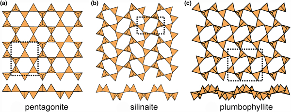
Above, we saw that in order for sheets to be modulated in a particular direction, the sheets must contain parallel ribbons of u tetrahedra and ribbons of d tetrahedra (Fig. 10b). A convenient way of classifying such modulated sheets is by the width (i.e. the number of tetrahedra) across the ribbon. The minimum width of these ribbons is two tetrahedra, and those structures thus formed are shown in Fig. 13. In pentagonite (Fig. 13a), there are two types of six-membered rings, (u2d4) and (u4d2), that share two adjacent similarly pointing tetrahedra to form ribbons of similarly pointing tetrahedra. Inspection of Fig. 13a shows no perceptible sign of modulation of the sheet, but the possibility of modulation exists in terms of the linkage of tetrahedra. In pentagonite, there are two interstitial cations, one V4+ coordinated by ![]() ${\rm O}_5^{{\rm 2\ndash}} $ and one Ca2+ coordinated by
${\rm O}_5^{{\rm 2\ndash}} $ and one Ca2+ coordinated by ![]() ${\rm O}_6^{{\rm 2\ndash}} $(H2O)t, plus an (H2O)z group. In silinaite, there is only one type of six-membered ring, (u3d3), that shares vertices with adjacent rings such that like-pointing tetrahedra form fairly extended ribbons (Fig. 13b), and there is a pronounced modulation with a wavelength of four tetrahedra orthogonal to these ribbons. There are two interstitial cations, Li+ coordinated by
${\rm O}_6^{{\rm 2\ndash}} $(H2O)t, plus an (H2O)z group. In silinaite, there is only one type of six-membered ring, (u3d3), that shares vertices with adjacent rings such that like-pointing tetrahedra form fairly extended ribbons (Fig. 13b), and there is a pronounced modulation with a wavelength of four tetrahedra orthogonal to these ribbons. There are two interstitial cations, Li+ coordinated by ![]() ${\rm O}_4^{{\rm 2\ndash}} $ and Na+ coordinated by
${\rm O}_4^{{\rm 2\ndash}} $ and Na+ coordinated by ![]() ${\rm O}_2^{{\rm 2\ndash}} $(H2O
${\rm O}_2^{{\rm 2\ndash}} $(H2O![]() $)_4^{\rm n} $.
$)_4^{\rm n} $.
Modulated 63 sheets (ribbon width = 2u2d tetrahedra) of u–d tetrahedra in (a) pentagonite, (b) silinaite and (c) plumbophyllite.
In plumbophyllite, there are two types of six-membered rings, (u4d2) and (u2d4), that share vertices with adjacent rings such that like-pointing tetrahedra form fairly extended ribbons (Fig. 13c), and there is a pronounced modulation with a wavelength of four tetrahedra orthogonal to these ribbons; however, note that the sheet is more folded than is the case in silinaite (Fig. 13b), and hence the modulation tends to appear blurred where viewed parallel to the ribbons (Fig. 13c). There is one interstitial lone-pair stereoactive Pb2+ cation coordinated by ![]() ${\rm O}_6^{{\rm 2\ndash}} $(H2O)t where the site containing (H2O) is only half-occupied.
${\rm O}_6^{{\rm 2\ndash}} $(H2O)t where the site containing (H2O) is only half-occupied.
Sheets with a ribbon width of four tetrahedra are shown in Fig. 14. In palygorskite (Fig. 14a) and raite (Fig. 14b), there are two types of six-membered rings, (u6) and (u3d3), that share three adjacent similarly pointing tetrahedra to form ribbons of similarly pointing tetrahedra four tetrahedra wide. There is only a very slight modulation of this sheet in palygorskite and a more prominent modulation in raite; the magnitude of the modulation is more a function of the strip of octahedra to which the sheet is attached than a characteristic of the sheet itself (Guggenheim and Eggleton, Reference Guggenheim and Eggleton1998). In palygorskite, the interstitial cations are all [6]-coordinated; there are two sites each half-occupied by Mg2+ and Al3+ (Giustetto and Chiari, Reference Giustetto and Chiari2004), plus interstitial (H2O) groups. In raite, there are two interstitial Mn2+ cations coordinated by ![]() ${\rm O}_4^{{\rm 2\ndash}} $(OH)2, two Na+ cations coordinated by
${\rm O}_4^{{\rm 2\ndash}} $(OH)2, two Na+ cations coordinated by ![]() ${\rm O}_6^{{\rm 2\ndash}} $ and (H2O)6, respectively, and one quarter-occupied site containing Ti4+ coordinated by
${\rm O}_6^{{\rm 2\ndash}} $ and (H2O)6, respectively, and one quarter-occupied site containing Ti4+ coordinated by ![]() ${\rm O}_2^{{\rm 2\ndash}} $(H2O)4.
${\rm O}_2^{{\rm 2\ndash}} $(H2O)4.
In kalifersite (Fig. 15a), there are two types of six-membered rings, (u6) and (d6), in the ratio 2:1. The (u6) rings link to form an upward-pointing ribbon six-tetrahedra wide, and these ribbons are linked laterally by a ribbon of (d6) rings that form a downward-pointing ribbon four-tetrahedra wide, forming a modulation in which the widths of the ribbons with like-pointing tetrahedra are different. The interstitial cations are five [6]-coordinated Fe2+ ions with coordinations ![]() ${\rm O}_6^{{\rm 2\ndash}} $ (×2) and
${\rm O}_6^{{\rm 2\ndash}} $ (×2) and ![]() ${\rm O}_4^{{\rm 2\ndash}} $(OH)2 (×3), and three K+ ions (+ minor Na+) with coordinations
${\rm O}_4^{{\rm 2\ndash}} $(OH)2 (×3), and three K+ ions (+ minor Na+) with coordinations ![]() ${\rm O}_2^{{\rm 2\ndash}} $(H2O)4 (×2) and (H2O)6. In sepiolite (Fig. 15b), there are two types of six-membered rings, (u6) and (d6), in the ratio 1:1. The (u6) rings link to form an upward-pointing ribbon six-tetrahedra wide, and the (d6) rings link to form a downward-pointing ribbon six-tetrahedra wide. Interstitial cations are four distinct Mg2+ ions with coordinations
${\rm O}_2^{{\rm 2\ndash}} $(H2O)4 (×2) and (H2O)6. In sepiolite (Fig. 15b), there are two types of six-membered rings, (u6) and (d6), in the ratio 1:1. The (u6) rings link to form an upward-pointing ribbon six-tetrahedra wide, and the (d6) rings link to form a downward-pointing ribbon six-tetrahedra wide. Interstitial cations are four distinct Mg2+ ions with coordinations ![]() ${\rm O}_4^{{\rm 2\ndash}} $(OH
${\rm O}_4^{{\rm 2\ndash}} $(OH![]() $)_2^\ndash $ (×3) and
$)_2^\ndash $ (×3) and ![]() ${\rm O}_4^{{\rm 2\ndash}} $(H2O
${\rm O}_4^{{\rm 2\ndash}} $(H2O![]() $)_2^{\rm t $ plus four interstitial (H2O)z sites that may show partial occupancy and positional disorder. In antigorite (Fig. 15c), there are four types of six-membered rings, (u6), (u4d2), (u2d4) and (d6), in the ratio 2:1:1:2. The (u6) and (u4d2) rings link to form an upward-pointing ribbon seven-tetrahedra wide, the (u2d42) and (d6) rings link to form a downward-pointing ribbon seven-tetrahedra wide, and antigorite shows the most prominent modulation of these modulated sheet-silicates.
$)_2^{\rm t $ plus four interstitial (H2O)z sites that may show partial occupancy and positional disorder. In antigorite (Fig. 15c), there are four types of six-membered rings, (u6), (u4d2), (u2d4) and (d6), in the ratio 2:1:1:2. The (u6) and (u4d2) rings link to form an upward-pointing ribbon seven-tetrahedra wide, the (u2d42) and (d6) rings link to form a downward-pointing ribbon seven-tetrahedra wide, and antigorite shows the most prominent modulation of these modulated sheet-silicates.
Modulated 63 sheets (ribbon width = 4u4d tetrahedra) of u–d tetrahedra in (a) palygorskite and (b) raite.
Modulated 63 sheets of u–d tetrahedra in (a) kalifersite (ribbon width = 6u4d), (b) sepiolite (ribbon width = 6u6d) and (c) antigorite (ribbon width = 7u7d).
Inspection of Figs 13–15 indicates that (u6) rings are generally much less distorted away from planar hexagonal symmetry than six-membered rings containing both u and d tetrahedra. It is obvious that commensurate modulation and folding are connected to linkage requirements between the sheets and the non-tetrahedrally coordinated parts of the structures, but the diversity of the latter, involving variations in stoichiometry, coordination number and ligancy of non-tetrahedrally coordinated cations, differing amounts of H and the ensuing hydrogen bond networks, are beyond the scope of the present work.
The 4.82 net
Details of the 4.82 net are shown in Fig. 2b. There are both four-membered and eight-membered rings but only one type of vertex: one four-membered ring and two eight-membered rings meet at each vertex, and the unit cell contains [Si4O10]. Table 5 lists the single-layer sheet-silicate minerals based on this net.
Single-layer sheet-silicates based on the 4.82, 4.6.12, (4.6.8)2(6.82)1, (52.8)2(5.82)1, (4.6.12), (4.6.10)4(62.10)1, (5.6.7)4(5.72)1(62.7)1 and (42.14)12(4.6.14)8(6.142)4 nets with mixed u–d arrangements.
References: (1) Foit et al. (Reference Foit, Phillips and Gibbs1973), Rinaldi et al. (Reference Rinaldi, Gatta and Angel2010); (2) Segalstad and Larsen (Reference Segalstad and Larsen1978), Demartin et al. (Reference Demartin, Pilati, Diella, Gentile and Gramaccioli1993); (3) Cámara et al. (Reference Cámara, Oberti, Ottolini, Della Ventura and Bellatreccia2008); (4) Ximen and Peng (Reference Ximen and Peng1985), Miyawaki et al. (Reference Miyawaki, Matsubara, Yokoyama and Okamoto2007); (5) Demartin et al. (Reference Demartin, Minaglia and Gramaccioli2001), Miyawaki et al. (Reference Miyawaki, Matsubara, Yokoyama and Okamoto2007); (6) Yakubovich et al. (Reference Yakubovich, Matvienko, Voloshin and Simonov1983); (7) Rastsvetaeva et al. (Reference Rastsvetaeva, Pushcharovskii, Pekov and Voloshin1996); (8) Miyawaki et al. (Reference Miyawaki, Nakai and Nagashima1985); (9) Foord et al. (Reference Foord, Gaines, Crock, Simmons and Barbosa1986); Cooper and Hawthorne (Reference Cooper and Hawthorne2017); (10) Bartl and Pfeifer (Reference Bartl and Pfeifer1976), Ståhl (Reference Ståhl1993); (11) Dunn et al. (Reference Dunn, Rouse, Norberg and Peacor1978); (12) Matsueda et al. (Reference Matsueda, Miura, Rucklidge and Kato1981); (13) Evans (Reference Evans1973); (14) Zubkova et al. (Reference Zubkova, Filinchuk, Pekov, Pushcharovsky and Gobechiya2010); (15) Zubkova et al. (Reference Zubkova, Filinchuk, Pekov, Pushcharovsky and Gobechiya2010); (16) Zubkova et al. (Reference Zubkova, Pekov, Pushcharovsky and Chukanov2009); (17) Chakoumakos et al. (Reference Chakoumakos, Fernandez-Baca and Boatner1993), Bensch and Schur (Reference Bensch and Schur1995); (18) Lin et al. (Reference Lin, Liao and Wang1992), Giester and Rieck (Reference Giester and Rieck1994), Knight et al. (Reference Knight, Henderson and Clark2010); (19) Pabst (Reference Pabst1943), Hazen and Finger (Reference Hazen and Finger1983); (20) Giester and Rieck (Reference Giester and Rieck1996); (21) Uvarova et al. (Reference Uvarova, Sokolova, Hawthorne, Agakhanov and Pautov2004a); (22) Szymański et al. (Reference Szymański, Owens, Roberts, Ansell and Chao1982); (23) Livingstone et al. (Reference Livingstone, Atkin and Hutchison1976); (24) Perrault and Szymański (Reference Perrault and Szymański1982); (25) Kabalov et al. (Reference Kabalov, Sokolova, Pautov and Schneider1998); (26) Yang et al. (Reference Yang, Downs, Yang and Allen2011); (27) Takeuchi et al. (Reference Takéuchi, Kawada, Irimaziri and Sadanaga1969), Kato and Takéuchi (Reference Kato and Takéuchi1983); (28) Kato and Watanabe (Reference Kato and Watanabe1992); (29) Ozawa et al. (Reference Ozawa, Takéuchi, Takahata, Donnay and Donnay1983); (30) Ozawa et al. (Reference Ozawa, Takéuchi, Takahata, Donnay and Donnay1983); (31) Dunn and Peacor (Reference Dunn and Peacor1984); (32) Kasahev and Sapozhnikov (Reference Kasahev and Sapozhnikov1978); (33) Fleet (Reference Fleet1965); (34) Gebert et al. (Reference Gebert, Medenbach and Flörke1983), Lazebnik et al. (Reference Lazebnik, Lazebnik and Makhotko1984); (35) Es'kova et al. (Reference Es'kova, Semenov, Khomyakov, Kazakova and Shumyatskaya1974), Shumyatsaya et al. (Reference Shumyatsaya, Voronkov and Pyatenko1980); (36) Cámara et al. (Reference Cámara, Ottolini, Devouard, Garvie and Hawthorne2006); (37) Alberti and Galli (Reference Alberti and Galli1983); (38) Merlino (Reference Merlino1983); (39) Uvarova et al. (Reference Uvarova, Sokolova, Hawthorne, Pautov and Agakhanov2004b); (40) Grice and Gault (Reference Grice and Gault1995); (41) Heinrich et al. (Reference Heinrich, Eggleton and Guggenheim1994); (42) Yamnova et al. (Reference Yamnova, Egorov-Tismenko and Khomyakov1996); and (43) Krivovichev et al. (Reference Krivovichev, Pakhomovsky, Ivanyuk, Mikhailova, Men'shikov, Armbruster, Selivanova and Meisser2007).
*P = planar; 1F = folded in one direction.
The minerals of the gadolinite supergroup (Table 5) show the simplest type of 4.82 net (Fig. 16a). The B3+ tetrahedra point both up and down in datolite, but do not project above or below the plane of the sheet. Instead, they link to Si4+ tetrahedra which have edges in the top and bottom surfaces of the sheet (Fig. 16b) and hence occur entirely within the body of the sheet. In general, the ordering of cations in this structure type is very strong, with Si4+ and (Be2+, B3+ and Al3+) occupying discrete tetrahedra (Fig. 16). Bačík et al. (Reference Bačik, Fridrichová, Uher, Pršek and Ondrejka2014) wrote the general formula of the minerals of this group as W2XZ2T2O8V2 where W = Ca2+, REE 3+ (Y3+ + lanthanoids), Bi3+; X = Fe2+, □ (vacancy), Mg2+, Mn2+, Zn2+, Cu2+, Al3+, Fe3+; Z = B3+, Be2+, Li+; T = Si4+, B3+, Be2+, S6+, P5+; V = O2–, OH–, F–, and divided the minerals into two subgroups on the basis of the Z-site occupancy: the datolite subgroup where Z = B3+, and the gadolinite subgroup where Z = Be2+. The interstitial cations occupy the W, X and Z sites. In the datolite-subgroup minerals, the W site is [8]-coordinated and is occupied by Ca2+ coordinated by ![]() ${\rm O}_6^{{\rm 2\ndash}} $(OH
${\rm O}_6^{{\rm 2\ndash}} $(OH![]() $)_2^\ndash $; the X site is vacant in datolite, and is occupied by Fe2+ in homilite (Table 5) where it is [6]-coordinated by
$)_2^\ndash $; the X site is vacant in datolite, and is occupied by Fe2+ in homilite (Table 5) where it is [6]-coordinated by ![]() ${\rm O}_4^{{\rm 2\ndash}} $(OH
${\rm O}_4^{{\rm 2\ndash}} $(OH![]() $)_2^\ndash $. In the gadolinite-subgroup minerals, the W site is [8]-coordinated and is occupied by REE 3+ coordinated by
$)_2^\ndash $. In the gadolinite-subgroup minerals, the W site is [8]-coordinated and is occupied by REE 3+ coordinated by ![]() ${\rm O}_6^{{\rm 2\ndash}} $(OH
${\rm O}_6^{{\rm 2\ndash}} $(OH![]() $)_2^\ndash $; the X site is vacant in hingganite minerals, and is occupied by Fe2+ in gadolinite minerals (Table 5) where it is [6]-coordinated by
$)_2^\ndash $; the X site is vacant in hingganite minerals, and is occupied by Fe2+ in gadolinite minerals (Table 5) where it is [6]-coordinated by ![]() ${\rm O}_4^{{\rm 2\ndash}} $(OH
${\rm O}_4^{{\rm 2\ndash}} $(OH![]() $)_2^\ndash $. Minasgeraisite-(Y) is more complicated as it has triclinic P1 (rather than monoclinic P21/a) symmetry; there is prominent order of Ca2+, Bi3+ and REE 3+ over four symmetrically distinct W sites and the two X sites are vacant (occupied by minor Mn2+). Moreover, preliminary results suggest that (at least) some hingganite minerals have similar symmetry and cation order as minasgeraisite-(Y) (Cooper and Hawthorne, Reference Cooper and Hawthorne2017).
$)_2^\ndash $. Minasgeraisite-(Y) is more complicated as it has triclinic P1 (rather than monoclinic P21/a) symmetry; there is prominent order of Ca2+, Bi3+ and REE 3+ over four symmetrically distinct W sites and the two X sites are vacant (occupied by minor Mn2+). Moreover, preliminary results suggest that (at least) some hingganite minerals have similar symmetry and cation order as minasgeraisite-(Y) (Cooper and Hawthorne, Reference Cooper and Hawthorne2017).
The 4.82 net and sheet in datolite; (a) the geometrically distorted 4.82 net; and (b) the sheet of tetrahedra.
The apophyllite-group minerals (Fig. 17a) and cavansite (Fig. 17b) have planar sheets. Both minerals have u and d tetrahedra in both four-membered and eight-membered rings. However, the patterns of u and d tetrahedra are different in both types of ring. In the apophyllite structure, there are (u4) and (d4) four-membered rings that combine to give (u2d2u2d2) eight-membered rings (Fig. 17a), whereas in cavansite, there is only one type of four-membered ring, (u2d2), that combines to give (u4d4) eight-membered rings (Fig. 17b). The interstitial complex in the apophyllite structure consists of one distinct Ca2+ ion that is [7]-coordinated by ![]() ${\rm O}_4^{{\rm 2\ndash}} $(F–,OH–)(H2O)2, and one K+ ion that is [8]-coordinated by (H2O)8. The interstitial complex in cavansite consists of one distinct Ca2+ ion that is [8]-coordinated by
${\rm O}_4^{{\rm 2\ndash}} $(F–,OH–)(H2O)2, and one K+ ion that is [8]-coordinated by (H2O)8. The interstitial complex in cavansite consists of one distinct Ca2+ ion that is [8]-coordinated by ![]() ${\rm O}_4^{{\rm 2\ndash}} $(H2O)4, and one V4+ ion that is [5]-coordinated by
${\rm O}_4^{{\rm 2\ndash}} $(H2O)4, and one V4+ ion that is [5]-coordinated by ![]() ${\rm O}_4^{{\rm 2\ndash}} $(OH)–.
${\rm O}_4^{{\rm 2\ndash}} $(OH)–.
Kinked planar 4.82 sheets of u–d tetrahedra in (a) apophyllite and (b) cavansite.
The 4.82 sheets in cryptophyllite, mountainite and shlykovite are shown in Fig. 18, and give us some insight into the coupling of u and d tetrahedra in the different rings. In all three structures, the four-membered rings have the configuration (u3d1). However, in cryptophyllite (Fig. 18a) and shlykovite (Fig. 18b), the eight-membered ring has the configuration (u4d1u2d1) whereas in mountainite (Fig. 18c), the eight-membered ring has the configuration (u3d1u3d1). Inspection of Fig. 18 shows how this difference arises. Each four-membered ring links to four other four-membered rings. In cryptophyllite and shlykovite, all adjacent four-membered rings have the same orientation, whereas in mountainite this is not the case. In mountainite (Fig. 18c), two adjacent four-membered rings have the same orientation and the other two four-membered rings have a different orientation (rotated by ~180°); the result is a different combination of u and d tetrahedra in the eight-membered rings formed by linkage of the four-membered rings. It is apparent that these differences in u–d arrangements of tetrahedra play a major role in the diversity of linkage to the non-tetrahedrally coordinated constituents of these structures, and this will be examined more rigorously in a later paper. The interstitial complex in cryptophyllite consists of one Ca2+ ion that is [6]-coordinated by O5(H2O), and two K+ ions [8]-coordinated by O6(H2O)2 and O3(H2O)5, respectively. The interstitial complex in shlykovite consists of one Ca2+ ion that is [6]-coordinated by ![]() ${\rm O}_5^{{\rm 2\ndash}} $(H2O), and one K+ ion that is [8]-coordinated by
${\rm O}_5^{{\rm 2\ndash}} $(H2O), and one K+ ion that is [8]-coordinated by ![]() ${\rm O}_6^{{\rm 2\ndash}} $(H2O)2. The interstitial complex in mountainite consists of one Ca2+ ion that is [6]-coordinated by O5(H2O), one K+ ion [8]-coordinated by O6(H2O)2, and one Na+ ion coordinated by
${\rm O}_6^{{\rm 2\ndash}} $(H2O)2. The interstitial complex in mountainite consists of one Ca2+ ion that is [6]-coordinated by O5(H2O), one K+ ion [8]-coordinated by O6(H2O)2, and one Na+ ion coordinated by ![]() ${\rm O}_2^{{\rm 2\ndash}} $(OH)–(H2O)5.
${\rm O}_2^{{\rm 2\ndash}} $(OH)–(H2O)5.
Planar 4.82 sheets of u–d tetrahedra in (a) cryptophyllite, (b) shlykovite and (c) mountainite.
Cuprorivaite (Fig. 19a) and ekanite (Fig. 19b) have doubly folded sheets with u and d tetrahedra in both four-membered and eight-membered rings. Unlike apophyllite (Fig. 17a) and cavansite (Fig. 17b), cuprorivaite and ekanite have the same pattern of u and d tetrahedra in their four-membered and eight-membered rings: (u4), (d4) and (u2d2u2d2). Thus the sheets in apophyllite and cavansite (Fig. 17), although based on the same type of 3-connected net, are significantly different, whereas the sheets in cuprorivaite and ekanite (Fig. 19) are topologically identical. There are four minerals with the cuprorivaite structure in the so-called ‘gillespite group’ (Table 5). The interstitial complex in these minerals consists of one distinct M2+ ion (M2+ = Ca2+, Ba2+ or Sr2+) that is [8]-coordinated by ![]() ${\rm O}_8^{{\rm 2\ndash}} $, and one Cu2+ (or Fe2+) ion that is [4]-coordinated by
${\rm O}_8^{{\rm 2\ndash}} $, and one Cu2+ (or Fe2+) ion that is [4]-coordinated by ![]() ${\rm O}_4^{{\rm 2\ndash}} $. There are five minerals in the ekanite group (Table 5). The interstitial complex in ekanite consists of one distinct Ca2+ ion that is [8]-coordinated by
${\rm O}_4^{{\rm 2\ndash}} $. There are five minerals in the ekanite group (Table 5). The interstitial complex in ekanite consists of one distinct Ca2+ ion that is [8]-coordinated by ![]() ${\rm O}_8^{{\rm 2\ndash}} $, and one Th4+ ion that is [8]-coordinated by
${\rm O}_8^{{\rm 2\ndash}} $, and one Th4+ ion that is [8]-coordinated by ![]() ${\rm O}_8^{{\rm 2\ndash}} $.
${\rm O}_8^{{\rm 2\ndash}} $.
Folded 4.82 sheets of u–d tetrahedra in (a) cuprorivaite and (b) ekanite.
The 3.122 net
As far as we are aware, there are no sheet-silicate minerals based on this 3-connected net, despite its simplicity. Three-membered rings are unusual in silicates but do occur, e.g. the benitoite-group minerals (Hawthorne, Reference Hawthorne1987). Possibly this is connected with the association of large and small rings in a sheet (Fig. 2c), although there are structures based on the 4.6.12 net. Perhaps the occurrence of an intermediate-sized ring relieves strain in the sheet.
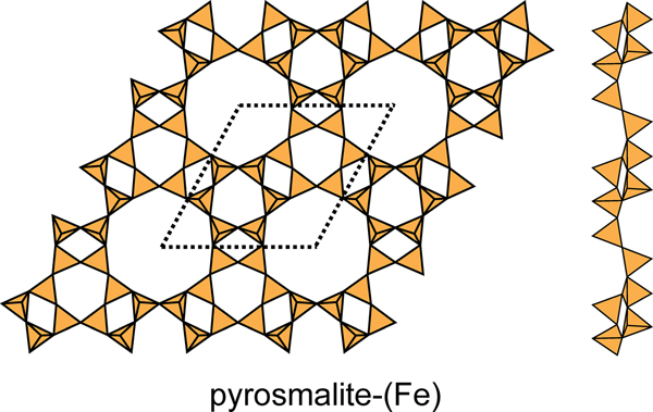
The 4.6.12 net
This net contains three four-membered rings, two six-membered rings and one twelve-membered ring in the unit cell (Fig. 2d) in the ratio 3:2:1, and there is only one type of vertex: (4.6.12) with 12 vertices per unit cell. There are six structures with sheets based on this net: pyrosmalite-(Fe), pyrosmalite-(Mn), schallerite, friedelite, mcgillite and nelenite (Table 5). The sheets are topologically identical in these minerals, but link to sheets of octahedra in different ways to form polytypes (Takéuchi et al., Reference Takéuchi, Ozawa and Takahata1983). In the sheets of schallerite and nelenite, an oxygen anion bridging two (SiO4) tetrahedra also links to an As3+ cation, thereby violating the valence-sum rule, and hence there must be significant disorder involving vacancies, Si4+ and As3+ that is not resolved in the current refined structure. The four-membered rings in the As3+-free minerals have the sequence (u2d2), there are two six-membered rings with the sequences (u6) and (d6), and one twelve-membered ring with the sequence (u2d2u2d2u2d2) (Fig. 20). Note that there is significant modulation of this sheet. The interstitial complex in the pyrosmalite-group minerals consists of four distinct M2+ ions (M2+ = Fe2+ or Mn2+) that are [6]-coordinated by ![]() ${\rm Cl}_6^\ndash $,
${\rm Cl}_6^\ndash $, ![]() ${\rm O}_4^{{\rm 2\ndash}} {\rm Cl}_2^\ndash $,
${\rm O}_4^{{\rm 2\ndash}} {\rm Cl}_2^\ndash $, ![]() ${\rm O}_6^{{\rm 2\ndash}} $ and
${\rm O}_6^{{\rm 2\ndash}} $ and ![]() ${\rm O}_5^{{\rm 2\ndash}} $Cl–, respectively.
${\rm O}_5^{{\rm 2\ndash}} $Cl–, respectively.
The 4.6.12 sheet in the structures of pyrosmalite-(Fe), pyrosmalite-(Mn) and schallerite. Note the slight modulation in the sheet.
The (4.6.8)2(6.82)1 net
Details of the (4.6.8)2(6.82)1 net are shown in Fig. 2e. This net contains four-, six- and eight-membered rings and there are two types of vertex: (4.6.8) and (6.82) in the ratio 2:1; the unit cell contains [Si6O15]. Table 5 lists the single-layer sheet-silicate minerals based on this net, and their structures are shown in Fig. 21. Despite the differing appearance of these sheets, they do show the linkage of this net, but differ in their patterns of u and d tetrahedron vertices (Table 5). In armstrongite (Fig. 21a), the four-membered and six-membered rings have the sequences (u2d2) and (ud3ud), and they link such that the eight-membered rings have the sequence (u4d4). In dalyite (Fig. 21b), all rings show the same u–d sequence as in armstrongite but the sheet is strongly sheared relative to that of armstrongite. The interstitial complex in armstrongite consists of one distinct Ca2+ ion that is [7]-coordinated by ![]() ${\rm O}_5^{{\rm 2\ndash}} $(H2O)2, and one Zr4+ that is coordinated by
${\rm O}_5^{{\rm 2\ndash}} $(H2O)2, and one Zr4+ that is coordinated by ![]() ${\rm O}_6^{{\rm 2\ndash}} $; there are two distinct interstitial transformer (H2O) groups. The interstitial complex in dalyite consists of one Na+ ion that is [8]-coordinated by
${\rm O}_6^{{\rm 2\ndash}} $; there are two distinct interstitial transformer (H2O) groups. The interstitial complex in dalyite consists of one Na+ ion that is [8]-coordinated by ![]() ${\rm O}_8^{{\rm 2\ndash}} $, and one Zr4+ ion that is [6]-coordinated by
${\rm O}_8^{{\rm 2\ndash}} $, and one Zr4+ ion that is [6]-coordinated by ![]() ${\rm O}_6^{{\rm 2\ndash}} $.
${\rm O}_6^{{\rm 2\ndash}} $.
Folded 4.6.8 sheets in the structures of (a) armstrongite, (b) dalyite and davanite, and (c) sazhinite-(Ce) and sazhinite-(La).
In sazhinite-(Ce) and sazhinite-(La) (Fig. 21c), four-membered rings have the sequences (u4) and (d4), six-membered rings have the sequences (u2du2d) and (ud2ud2), and they link such that the eight-membered rings have the sequence (u2dud2ud). These structures show an interesting contrast with the structures of the 4.82 net (Figs 4b, 10; Table 5); they are each folded, as is apparent in Fig. 21, but unlike the 4.82 structure of Fig. 5b, they are folded only in one direction. The interstitial complex in sazhinite-(Ce) and sazhinite-(La) consists of one distinct M3+ ion that is [7]-coordinated by ![]() ${\rm O}_7^{{\rm 2\ndash}} $, and two Na+ ions, the coordination of which is somewhat ambiguous: there is one Na+ ion with a coordination of either
${\rm O}_7^{{\rm 2\ndash}} $, and two Na+ ions, the coordination of which is somewhat ambiguous: there is one Na+ ion with a coordination of either ![]() ${\rm O}_5^{{\rm 2\ndash}} $ or
${\rm O}_5^{{\rm 2\ndash}} $ or ![]() ${\rm O}_5^{{\rm 2\ndash}} $(H2O), and one Na+ ion with a coordination of either
${\rm O}_5^{{\rm 2\ndash}} $(H2O), and one Na+ ion with a coordination of either ![]() ${\rm O}_3^{{\rm 2\ndash}} $(H2O)2 or
${\rm O}_3^{{\rm 2\ndash}} $(H2O)2 or ![]() ${\rm O}_3^{{\rm 2\ndash}} $(H2O)5; one (H2O) group is either a hydrogen-bonded group or an inverse transformer group, depending on the coordinations chosen for the Na+ cations, and the other (H2O) group is a hydrogen-bonded group.
${\rm O}_3^{{\rm 2\ndash}} $(H2O)5; one (H2O) group is either a hydrogen-bonded group or an inverse transformer group, depending on the coordinations chosen for the Na+ cations, and the other (H2O) group is a hydrogen-bonded group.
The (52.8)2(5.82)1 net
This net contains 5- and 8-membered rings (Fig. 2f) and there are two types of vertex: (52.8) and (5.82) in the ratio 2:1; the unit cell contains [Si6O15], and this net topology occurs in the structures of nekoite, okenite and zeravshanite (Table 5). Nekoite (Fig. 22a), has two distinct five-membered rings with u–d arrangements (u3d2) and (u2dud) and one eight-membered ring with the arrangement (u6d2), and the sheet is planar. Okenite (Fig. 22b) has one distinct five-membered ring with the u–d arrangement (u4d) and one eight-membered ring with the arrangement (u7d), and the sheet is also planar. Thus the sheets in nekoite and okenite are geometrical isomers, they have the same topology (connectivity of chemical bonds) but the geometrical details are distinct in that the u–d arrangements of tetrahedra are different in each mineral. In okenite, the sheets alternate with layers of [Si6O16] chains (Fig. 22c) which has the stoichiometric effect of decreasing the connectivity of the silicate part of the structure (Table 5).
Planar (52.8)2(5.82)1 sheets in the structures of (a) nekoite; (b) okenite; (c) chains of tetrahedra in okenite; and (d) zeravshanite; note the one-dimensional folding of the silicate sheet in zeravshanite. Legend as in Fig. 1.
Zeravshanite (Fig. 22d) is significantly different. It has two distinct five-membered rings with u–d arrangements (u3d2) and (u2d3) and one eight-membered ring with the arrangement (u4d4). Moreover, unlike nekoite and okenite, the sheet in zeravshanite is folded in one direction. The interstitial complex in nekoite consists of three distinct Ca2+ ions that are all [6]-coordinated by ![]() ${\rm O}_4^{{\rm 2\ndash}} $(H2O)2; there are seven distinct (H2O) groups, four are transformer, one is non-transformer and two are hydrogen bonded only. The interstitial complex in okenite consists of six distinct sites occupied by Ca2+ ions; four of these sites are fully occupied and are [6]-coordinated by
${\rm O}_4^{{\rm 2\ndash}} $(H2O)2; there are seven distinct (H2O) groups, four are transformer, one is non-transformer and two are hydrogen bonded only. The interstitial complex in okenite consists of six distinct sites occupied by Ca2+ ions; four of these sites are fully occupied and are [6]-coordinated by ![]() ${\rm O}_5^{{\rm 2\ndash}} $(H2O) (×3) and
${\rm O}_5^{{\rm 2\ndash}} $(H2O) (×3) and ![]() ${\rm O}_6^{{\rm 2\ndash}} $, and two are half-occupied and coordinated by
${\rm O}_6^{{\rm 2\ndash}} $, and two are half-occupied and coordinated by ![]() ${\rm O}_2^{{\rm 2\ndash}} $(H2O)5 and (H2O)6, respectively. There are thirteen distinct (H2O) sites, not all of which are fully occupied; four (H2O) groups are transformer, seven are non-transformer and two are hydrogen-bonded only. The interstitial complex in zeravshanite consists of two Cs+ ions coordinated by
${\rm O}_2^{{\rm 2\ndash}} $(H2O)5 and (H2O)6, respectively. There are thirteen distinct (H2O) sites, not all of which are fully occupied; four (H2O) groups are transformer, seven are non-transformer and two are hydrogen-bonded only. The interstitial complex in zeravshanite consists of two Cs+ ions coordinated by ![]() ${\rm O}_9^{{\rm 2\ndash}} $ and
${\rm O}_9^{{\rm 2\ndash}} $ and ![]() ${\rm O}_8^{{\rm 2\ndash}} $, respectively, one Na+ ion coordinated by
${\rm O}_8^{{\rm 2\ndash}} $, respectively, one Na+ ion coordinated by ![]() ${\rm O}_6^{{\rm 2\ndash}} $(H2O)2, and two Zr4+ ions each of which are coordinated by
${\rm O}_6^{{\rm 2\ndash}} $(H2O)2, and two Zr4+ ions each of which are coordinated by ![]() ${\rm O}_6^{{\rm 2\ndash}} $. There is one interstitial transformer (H2O) group.
${\rm O}_6^{{\rm 2\ndash}} $. There is one interstitial transformer (H2O) group.
Miscellaneous nets
There are several nets (Table 5) that just have just one example each of a sheet-silicate unit.
The (4.6.10)4(62.10)1 net has four-membered, six-membered and ten-membered rings in the ratio 2:2:1 (Fig. 23a). In the structure of varennesite (Table 5), all four-membered rings have the u–d arrangement (u2d2), the six-membered rings have the arrangements (u6) and (d6), and the two types of ten-membered ring have the arrangements (u3d2u3d2) and (d3u2d3u2). The sheet is planar but with a strong modulation in both directions (Fig. 23a). The interstitial complex in varennesite consists of three Na+ ions coordinated by ![]() ${\rm O}_4^{{\rm 2\ndash}} $(OH)–(H2O),
${\rm O}_4^{{\rm 2\ndash}} $(OH)–(H2O), ![]() ${\rm O}_3^{{\rm 2\ndash}} $(H2O)3, and
${\rm O}_3^{{\rm 2\ndash}} $(H2O)3, and ![]() ${\rm O}_2^{{\rm 2\ndash}} $(H2O)4, and one Mn2+ ion coordinated by
${\rm O}_2^{{\rm 2\ndash}} $(H2O)4, and one Mn2+ ion coordinated by ![]() ${\rm O}_4^{{\rm 2\ndash}} $(OH
${\rm O}_4^{{\rm 2\ndash}} $(OH![]() $)_2^\ndash $; there are six interstitial (H2O) groups, five of which are non-transformer and one of which is hydrogen-bonded only.
$)_2^\ndash $; there are six interstitial (H2O) groups, five of which are non-transformer and one of which is hydrogen-bonded only.
Miscellaneous 3-connected plane nets and their corresponding structures; (a) the (4.6.10)4(62.10)1 net and sheet in varennesite; (b) the (5.6.7)4(5.72)1(62.7)1 net and sheet in bementite; and (c) the (52.8)1(5.62)1(5.6.8)2(62.8)1 net and sheet in intersilite.
The (5.6.7)4(5.72)1(62.7)1 net has five-membered, six-membered and seven-membered rings in the ratio 1:1:1 (Fig. 23b). In the structure of bementite (Table 5), there are two types of five-membered rings with u–d arrangements (u3d2) and (u2d3), two types of six-membered rings with the arrangements (u6) and (d6), and the two types of seven-membered rings with the arrangements (u5d) and (u2d5). The sheet is planar but with a modulation in one direction (Fig. 23b). The interstitial complex in bementite consists of fifteen distinct Mn2+ ions all of which are [6]-coordinated by ![]() ${\rm O}_2^{{\rm 2\ndash}} $(OH
${\rm O}_2^{{\rm 2\ndash}} $(OH![]() $)_4^\ndash $ (×6),
$)_4^\ndash $ (×6), ![]() ${\rm O}_3^{{\rm 2\ndash}} $(OH
${\rm O}_3^{{\rm 2\ndash}} $(OH![]() $)_3^\ndash $ (×7) and
$)_3^\ndash $ (×7) and ![]() ${\rm O}_4^{{\rm 2\ndash}} $(OH
${\rm O}_4^{{\rm 2\ndash}} $(OH![]() $)_2^\ndash $ (×2).
$)_2^\ndash $ (×2).
The (52.8)1(5.62)1(5.6.8)2(62.8)1 net has five-membered, six-membered and eight-membered rings in the ratio 2:2:1 (Fig. 23c). In the structure of intersilite (Table 5), there are two types of five-membered rings with u–d arrangements (u2dud) and (udud2), three types of six-membered rings with the arrangements (u6), (u3d3) and (d6), and two types of eight-membered rings with the arrangements (u4du2d) and (d4ud2u). The sheet is planar (Fig. 23c) with no significant modulation. The interstitial cations in intersilite consists of Mn2+, Ti4+ and Na+, but the interatomic distances and coordinations are not compatible with these cations, suggesting considerable positional disorder between the sheets.
The (42.14)12(4.6.14)8(6.142)4 net has four-membered, six-membered and fourteen-membered rings in the ratio 3:2:1 (Fig. 24a). In the structure of yakovenchukite-(Y) (Fig. 24b; Table 5), there is one type of four-membered ring with the arrangement (u2d2), two types of six-membered ring with the arrangements (u2du2d) and (ud2ud2), and one type of fourteen-membered ring with the arrangement (ud2ud2udu2du2d). The sheet is folded in one direction (Fig. 24b). The interstitial complex in yakovenchukite-(Y) consists of two K+ (+ some Na+) ions coordinated by ![]() ${\rm O}_7^{{\rm 2\ndash}} $(H2O)2 and
${\rm O}_7^{{\rm 2\ndash}} $(H2O)2 and ![]() ${\rm O}_7^{{\rm 2\ndash}} $(H2O), two Ca2+ ions coordinated by
${\rm O}_7^{{\rm 2\ndash}} $(H2O), two Ca2+ ions coordinated by ![]() ${\rm O}_6^{{\rm 2\ndash}} $(H2O)2 and
${\rm O}_6^{{\rm 2\ndash}} $(H2O)2 and ![]() ${\rm O}_5^{{\rm 2\ndash}} $(H2O), and two Y3+ ions each of which is coordinated by
${\rm O}_5^{{\rm 2\ndash}} $(H2O), and two Y3+ ions each of which is coordinated by ![]() ${\rm O}_6^{{\rm 2\ndash}} $; there are three interstitial (H2O) groups, two of which are non-transformer and one of which is hydrogen-bonded only.
${\rm O}_6^{{\rm 2\ndash}} $; there are three interstitial (H2O) groups, two of which are non-transformer and one of which is hydrogen-bonded only.
Miscellaneous 3-connected plane nets and their corresponding structures; (a) the (42.14)12(4.6.14)8(6.142)4 net, and (b) the sheet in yakovenchukite-(Y).
Single-layer sheets: 3- and 4-connected nets with inserted 2- and 3-connected vertices
Many single-sheet silicate minerals contain 4-connected tetrahedra in addition to tetrahedra of lower connectivity. Hawthorne (Reference Hawthorne2015a) showed how suitable planar nets may be derived for these minerals by insertion of lower-connectivity vertices into planar 3- and 4-connected nets. It is not straightforward to insert vertices into a 3-connected net to produce a net of 3- and 4-connected vertices that forms a suitable basis for a sheet of tetrahedra, although it is feasible. Figure 25a shows the 63 net with pairs of 2-connected vertices inserted on one pair of trans edges of each six-membered ring; examination of the plan and horizontal views shows that the original 3-connected vertices are converted to 4-connected vertices. The result is a (4.8)2(4.83)2 net with only 2- and 4-connected vertices. Figure 25b shows the corresponding net for the sheet of tetrahedra in amstallite (Table 6); the unit cell is doubled, (4.8)4(4.83)4, due to geometrical distortion. The plan and horizontal views of the sheet in amstallite are shown in Figs 25c,d. Alternatively, the tetrahedra in amstallite could be considered as a double-layer sheet in which a pair of 2-connected vertices are inserted into trans edges of the 63 net with the 2-connected vertices out of the geometric plane of the 63 net; an oikodoméic m operation then repeats the 2-connected vertices below the geometric plane to produce a sheet with the cross-sectional aspect shown in Fig. 25d. The interstitial complex in amstallite consists of one Ca2+ ion coordinated by ![]() ${\rm O}_2^{{\rm 2\ndash}} $(OH
${\rm O}_2^{{\rm 2\ndash}} $(OH![]() $)_4^\ndash $ (H2O)2 and one Al3+ ion coordinated by
$)_4^\ndash $ (H2O)2 and one Al3+ ion coordinated by ![]() ${\rm O}_2^{{\rm 2\ndash}} $(OH
${\rm O}_2^{{\rm 2\ndash}} $(OH![]() $)_4^\ndash $; there is one interstitial transformer (H2O) group.
$)_4^\ndash $; there is one interstitial transformer (H2O) group.
Insertion of pairs of 2-connected vertices into the 63 net; (a) view and cross-section of the inserted 63 net; (b) the net of the sheet of tetrahedra in amstallite; (c) the sheet of tetrahedra in amstallite; and (d) horizontal view of the sheet of tetrahedra in amstallite. Legend as in Fig. 1, yellow vertices and tetrahedra are 2-connected.
Single-layer sheet-silicates based on nets with 3- and 4-connected vertices.
References: (1) Quint (Reference Quint1987); (2) Papike and Zoltai (Reference Papike and Zoltai1967), Baur et al. (Reference Baur, Joswig, Kassner and Hofmeister1990); (3) Ghose and Wan (Reference Ghose and Wan1976); (4) Kimata (Reference Kimata1981); (5) Louisnathan (Reference Louisnathan1970), Wiedenmann et al. (Reference Wiedenmann, Zaitsev, Britvin, Krivovichev and Keller2009); (6) Dondi et al. (Reference Dondi, Ercolani, Fabbri and Marsigli1999); (7) Louisnathan (Reference Louisnathan1971), Kimata and Li (Reference Kimata and Li1982); (8) Kimata and Ohashi (Reference Kimata and Ohashi1982), Yang et al. (Reference Yang, Fleck, Pertlik, Tillmanns and Tao2001); (9) Louisnathan (Reference Louisnathan1969), Bindi et al. (Reference Bindi, Czank, Röthlisberger and Bonazzi2001); (10) Matsubara et al. (Reference Matsubara, Miyawaki, Kato, Yokoyama and Okamoto1998); (11) Cannillo et al. (Reference Cannillo, Giuseppetti and Tazzoli1967, Reference Cannillo, Giuseppetti, Mazzi and Tazzoli1992), Grice and Hawthorne (Reference Grice and Hawthorne1989); (12) Dal Negro et al. (Reference Dal Negro, Rossi and Ungaretti1967), Grice and Hawthorne (Reference Grice and Hawthorne2002); (13) Grice and Robinson (Reference Grice and Robinson1984); (14) Della Ventura et al. (Reference Della Ventura, Bonazzi, Oberti and Ottolini2002), Oberti et al. (Reference Oberti, Langone, Boiocchi, Hawthorne and Bernabé2018); (15) Oberti et al. (Reference Oberti, Ottolini, Camara and Della Ventura1999), Oberti et al. (Reference Oberti, Langone, Boiocchi, Hawthorne and Bernabé2018); (16) Mellini and Merlino (Reference Mellini and Merlino1977), Miyawaki et al. (Reference Miyawaki, Momma, Yokoyama, Shigeoka, Matsubara, Ito, Nakai and Kristiansen2015); (17) Hawthorne et al. (Reference Hawthorne, Cooper and Taylor1998); (18) Boiocchi et al. (Reference Boiocchi, Callegari and Ottolini2006); (19) Bakakin et al. (Reference Bakakin, Belov, Borisov and Solovyeva1970), Pekov et al. (Reference Pekov, Chukanov, Kononkova, Belakovsky, Pushcharovsky and Vinogradova1998, Reference Pekov, Chukanov, Turchkova and Grishin2001), Pushcharovskii et al. (Reference Pushcharovskii, Pekov, Pluth, Smith, Ferraris, Vinogradova, Arakcheeva, Soboleva and Semenov1999); (20) Pekov et al. (Reference Pekov, Chukanov, Kononkova, Belakovsky, Pushcharovsky and Vinogradova1998), Pushcharovskii et al. (Reference Pushcharovskii, Pekov, Pluth, Smith, Ferraris, Vinogradova, Arakcheeva, Soboleva and Semenov1999); (21) Mazzi et al. (Reference Mazzi, Ungaretti, Dal Negro, Petersen and Rönsbo1979); (22) Hesse and Stümpel (Reference Hesse and Stümpel1986); (23) Danisi et al. (Reference Danisi, Armbruster, Libowitzky, Wang, Gunther, Nagashima, Reusser and Bieri2015); (24) Huminicki and Hawthorne (Reference Huminicki and Hawthorne2002b); (25) Grice et al. (Reference Grice, Rowe, Poirier, Pratt and Francis2009); (26) Chakhmouradian et al. (Reference Chakhmouradian, Cooper, Ball, Reguir, Medici, Abdu and Antonov2014); (27) Rouse et al. (Reference Rouse, Peacor, Dunn, Su, Chi and Yeates1994); and (28) Garcés et al. (Reference Garcés, Rocke, Crowder and Hasha1988).
*P = planar; 1F = folded in one direction.
It is much more straightforward to generate nets of 3- and 4-connected vertices by inserting 2- or 3-connected vertices into a 4-connected net. Consider the structure of prehnite (Table 6) in which the sheet of tetrahedra are 2-connected (yellow) and 4-connected (orange) (Fig. 26a). The net representation (Fig. 26b) consists of a plane 4-connected net 44 shown in which two 2-connected vertices are inserted on adjacent edges of each four-membered ring to form a (62)2(64)2 net with a u–d arrangement (udo3); this net is topologically identical to the ideal inserted 44 net (Fig. 26c). The interstitial complex in prehnite consists of one Ca2+ ion coordinated by ![]() ${\rm O}_7^{{\rm 2\ndash}} $ and one Al3+ ion coordinated by
${\rm O}_7^{{\rm 2\ndash}} $ and one Al3+ ion coordinated by ![]() ${\rm O}_6^{{\rm 2\ndash}} $.
${\rm O}_6^{{\rm 2\ndash}} $.
Insertion of 3-connected vertices into the 44 net; (a) the sheet of 2- and 4-connected tetrahedra in prehnite; (b) the corresponding net in the aluminosilicate sheet in prehnite; and (c) the sheet of 2- and 4-connected tetrahedra in prehnite. Red circles: 4-connected vertices; yellow circles: 2-connected vertices.
Figure 27a shows a parent 4-connected net with a 2-connected vertex inserted on one edge of each four-membered ring such that each vertex in the parent net is adjacent to only one 2-connected vertex. Figure 27b shows the analogous net in searlesite (Table 6) and Fig. 27c shows the corresponding sheet of tetrahedra in searlesite. All borate tetrahedra are 2-connected and all silicate tetrahedra are 4-connected, and the u–d arrangement is (uo4) (do4) in the ratio 1:1. The net corresponds to (54) and is crinkled in three dimensions in order to allow four five-membered rings to be incident at a single vertex. The interstitial complex in searlesite consists of one Na+ ion [6]-coordinated by ![]() ${\rm O}_2^{{\rm 2\ndash}} $(OH
${\rm O}_2^{{\rm 2\ndash}} $(OH![]() $)_4^\ndash $.
$)_4^\ndash $.
(a) A parent 4-connected net with a 2-connected vertex inserted on one edge of each four-membered ring such that each vertex in the parent net is adjacent to only one 2-connected vertex; (b) the analogous net in searlesite; and (c) the corresponding sheet of tetrahedra in searlesite. All borate tetrahedra are 2-connected and all silicate tetrahedra are 4-connected. The net corresponds to 54 and is crinkled in three dimensions in order to allow four 5-membered rings to be incident at a single vertex; yellow circles: 2-connected vertices.
In Fig. 28a, we see a parent (44)1 net completely inserted with 3-connected vertices with the edges between the 3-connected vertices parallel and perpendicular to the edges of the parent net. The 3-connected vertices occupying trans edges of the original (44)1 net link across the original four-membered ring, and the transitivity requirements of translational symmetry require edge-adjacent squares to be oriented differently (i.e. rotated by 90°). The result is a net with both 3- and 4-connected vertices: (53)2(54)1. Figure 28b shows a geometrically distorted version of this net, with the unit cells of the melilite-group minerals and leucophanite shown as the dotted lines, and the unit cell of meliphanite shown by the dashed lines. The (53)2(54)1 net contains only five-membered rings (Fig. 28a) with one 4-connected vertex and two 3-connected vertices. The assignment of u and d tetrahedra is now complicated by the presence of 4-connected tetrahedra that point neither up nor down (cf. Fig. 5b); we denote these tetrahedra as o. Thus there are two distinct five-membered rings in this net: (u2odo) and (uod2o). The 4-connected tetrahedron (corresponding to the red vertex in Fig. 28a) can accept a wide range of cations (Mg2+, Be2+, Zn2+, B3+, Al3+ and Fe3+) in minerals (Table 6) and other compositions with this structure type that have been synthesised (Kimata, Reference Kimata1983, Reference Kimata1985, Reference Kimata1988). The 3-connected tetrahedron can incorporate B3+, Al3+ and Si4+ in minerals (Table 6). As is typical for 4-connected tetrahedra in sheets, the tetrahedra are arranged such that two of their edges lie on the surfaces of the sheet, and the anions at the terminations of these edges can be ligands for 3-connected tetrahedra that point accordingly both u and d in the sheet (e.g. Fig. 29a). Many structures based on this net show incommensurate behaviour (see Armbruster et al., Reference Armbruster, Röthlisberger and Seifert1990). The interstitial complex in the melilite-group minerals consists of a single M site occupied by Ca2+ (except in alumoåkermanite, Table 6) that is [8]-coordinated by O2– anions. In leucophanite and meliphanite, the topological unit cells and the u–d–o arrangements are the same but the ordering of cations over the net-vertices/tetrahedra is different. In leucophanite, (Fig. 29b), the 4-connected tetrahedron is occupied by Si4+ and half of the 3-connected tetrahedra are occupied by Be2+. In meliphanite, (Fig. 29c), half of the 4-connected tetrahedra are occupied by Al3+ and half of the 3-connected tetrahedra are occupied by Be2+. The structure of jeffreyite is not yet known. The interstitial complex in leucophanite consists of one Ca2+ ion and one Na+ ion each of which is coordinated by ![]() ${\rm O}_8^{{\rm 2\ndash}} $; the interstitial complex in meliphanite consists of one Ca2+ ion and one Na+ ion with coordinations
${\rm O}_8^{{\rm 2\ndash}} $; the interstitial complex in meliphanite consists of one Ca2+ ion and one Na+ ion with coordinations ![]() ${\rm O}_7^{{\rm 2\ndash}} F^{\ndash}$ and
${\rm O}_7^{{\rm 2\ndash}} F^{\ndash}$ and ![]() ${\rm O}_6^{{\rm 2\ndash}} {\rm F}_2^\ndash $, respectively.
${\rm O}_6^{{\rm 2\ndash}} {\rm F}_2^\ndash $, respectively.
Insertion of 3-connected vertices into the 44 net; (a) the 44 net with 3-connected vertices inserted into trans edges of the net; and (b) geometrically distorted version of the net in Fig. 25a; the unit cell of the nets in åkermanite, leucophanite and meliphanite are marked by dotted, dotted and dashed lines, respectively.
Structures based on the 532541 net; (a) åkermanite; (b) leucophanite; and (c) meliphanite.
Figure 30 shows the related nets (4.5.8)2(4.52.8)2(53)2(52.8)4 and (4.5.8)2(4.52.8)2(53)6(52.8)4(54)2. The (4.5.8)2(4.52.8)2(53)2(52.8)4 net corresponds to the sheet in the structures of the hellandite-group minerals (Fig. 30a; Table 6) with a rather complicated u–d–o arrangement: (uodo)(u3do)(ud3o)(u2d2o)(u3od3o), and the net (4.5.8)2(4.52.8)2(53)6(52.8)4(54)2 corresponds to the sheet in the structure of piergorite-(Ce) with the same u-d-o arrangement (Fig. 30b; Table 6). Oberti et al. (Reference Oberti, Della Ventura, Ottolini, Hawthorne and Bonazzi2002) discussed the crystal chemistry of the hellandite-group minerals and wrote their general formula as X4Y2ZT2[B2Si4O22]W2 where X = Na+, Ca2+, Y3+, LREE 3+ at the M3 and M4 sites with coordinations ![]() ${\rm O}_8^{{\rm 2\ndash}} $ and
${\rm O}_8^{{\rm 2\ndash}} $ and ![]() ${\rm O}_7^{{\rm 2\ndash}} $(OH–,F–), respectively [except in ciprianiite and mottanaite-(Ce) where it is
${\rm O}_7^{{\rm 2\ndash}} $(OH–,F–), respectively [except in ciprianiite and mottanaite-(Ce) where it is ![]() ${\rm O}_8^{{\rm 2\ndash}} $ (×2)]; Y = Ca2+, Y3+, HREE 3+, Th4+, U4+ at the M2 site which is coordinated by
${\rm O}_8^{{\rm 2\ndash}} $ (×2)]; Y = Ca2+, Y3+, HREE 3+, Th4+, U4+ at the M2 site which is coordinated by ![]() ${\rm O}_7^{{\rm 2\ndash}} $(OH)– [except in ciprianiite and mottanaite-(Ce) where it is
${\rm O}_7^{{\rm 2\ndash}} $(OH)– [except in ciprianiite and mottanaite-(Ce) where it is ![]() ${\rm O}_8^{{\rm 2\ndash}} $ (×2)]; Z = Al3+, Mn3+, Fe3+ and Ti4+ at the M1 site which is coordinated by
${\rm O}_8^{{\rm 2\ndash}} $ (×2)]; Z = Al3+, Mn3+, Fe3+ and Ti4+ at the M1 site which is coordinated by ![]() ${\rm O}_4^{{\rm 2\ndash}} $(OH–)2; T = □ (vacancy), Li+ or Be2+ at a new tetrahedrally coordinated site; and W = (OH)–, F–, O2– at the O5 site. The interstitial complex in piergorite-(Ce) consists of four Ca2+ ions coordinated by
${\rm O}_4^{{\rm 2\ndash}} $(OH–)2; T = □ (vacancy), Li+ or Be2+ at a new tetrahedrally coordinated site; and W = (OH)–, F–, O2– at the O5 site. The interstitial complex in piergorite-(Ce) consists of four Ca2+ ions coordinated by ![]() ${\rm O}_8^{{\rm 2\ndash}} $ (×3) and
${\rm O}_8^{{\rm 2\ndash}} $ (×3) and ![]() ${\rm O}_7^{{\rm 2\ndash}} $(OH)–, one Ce3+ ion coordinated by
${\rm O}_7^{{\rm 2\ndash}} $(OH)–, one Ce3+ ion coordinated by ![]() ${\rm O}_7^{{\rm 2\ndash}} $(OH)–, and Al3+ coordinated by
${\rm O}_7^{{\rm 2\ndash}} $(OH)–, and Al3+ coordinated by ![]() ${\rm O}_4^{{\rm 2\ndash}} $(OH
${\rm O}_4^{{\rm 2\ndash}} $(OH![]() $)_2^\ndash $.
$)_2^\ndash $.
(a) The (4.5.8)2(4.52.8)2(53)2(52.8)4 net and sheet in the hellandite structure; and (b) the (4.5.8)2(4.52.8)2(53)6(52.8)4(54)2 net and sheet in piergorite-(Ce).
The (4.5.8)8(52.8)4(5.8.5.8)2 net has four-membered, five-membered and eight-membered rings in the ratio 4:2:1 (Fig. 31). There is one type of four-membered ring with the arrangement (u2d2), two types of five-membered rings with the arrangements (u3do) and (ud3o), and one type of eight-membered ring with the arrangement (u3od3o). This sheet occurs in the minerals of the nordite group: ferronordite-(Ce) and manganonordite-(Ce) (Table 6). Note that the unit cell of the net is half that of the sheet; this is the case because vertices of the net do not represent the u–d nature of the corresponding tetrahedra (unless we label them as such) whereas the u–d nature of tetrahedra is a property of the sheet. For ferronordite-(Ce), tetrahedra corresponding to translationally equivalent vertices point in different directions, causing a doubling of the unit cell in that direction (Fig. 31). The interstitial complex in ferronordite-(Ce), ferronordite-(La) and manganonordite-(Ce) consists of two Na+ ions each coordinated by ![]() ${\rm O}_6^{{\rm 2\ndash}} $, one Sr2+ ion coordinated by
${\rm O}_6^{{\rm 2\ndash}} $, one Sr2+ ion coordinated by ![]() ${\rm O}_8^{{\rm 2\ndash}} $, and one REE 3+ ion coordinated by
${\rm O}_8^{{\rm 2\ndash}} $, and one REE 3+ ion coordinated by ![]() ${\rm O}_8^{{\rm 2\ndash}} $.
${\rm O}_8^{{\rm 2\ndash}} $.
The (4.5.8)8(52.8)4(5.8.5.8)2 net and corresponding sheet of tetrahedra in ferronordite-(Ce).
The [(4.52)1(4.5.8.5)1(52.8)3]4 net has four-membered, five-membered and eight-membered rings in the ratio 1:1:3 (Fig. 32). There is one type of four-membered ring with the arrangement (uodo), two types of five-membered rings with the arrangements (u3do) and (ud3o), and one type of eight-membered ring with the arrangement (u3od3o). This sheet occurs in the structures of semenovite-(Ce), harstigite and perettiite-(Y) (Table 6). In semenovite-(Ce) (Fig. 32a), the tetrahedra are completely occupied by Si4+. In harstigite (Fig. 32b), the 4-connected tetrahedron and one 3-connected tetrahedron are occupied by Be2+ and the remaining 3-connected tetrahedra are occupied by Si4+. In perettiite-(Y) (Fig. 32c), one 3-connected tetrahedron is occupied by Si4+ and the remaining 3- and 4-connected tetrahedra are occupied by B3+; one 3-connected tetrahedron is partly occupied by Be2+, and this tetrahedron corresponds to that 3-connected tetrahedron occupied by Be2+ in harstigite (Fig. 32b). The interstitial complex in semenovite-(Ce) consists of two Ce3+ ions each coordinated by ![]() ${\rm O}_8^{{\rm 2\ndash}} $, two Fe2+ ions each coordinated by
${\rm O}_8^{{\rm 2\ndash}} $, two Fe2+ ions each coordinated by ![]() ${\rm O}_6^{{\rm 2\ndash}} $, and two Ca2+ ions (with minor Na+ substitution) coordinated by
${\rm O}_6^{{\rm 2\ndash}} $, and two Ca2+ ions (with minor Na+ substitution) coordinated by ![]() ${\rm O}_8^{{\rm 2\ndash}} $ and
${\rm O}_8^{{\rm 2\ndash}} $ and ![]() ${\rm O}_7^{{\rm 2\ndash}} $F–, respectively. The interstitial complex in harstigite consists of three Ca2+ ions coordinated by
${\rm O}_7^{{\rm 2\ndash}} $F–, respectively. The interstitial complex in harstigite consists of three Ca2+ ions coordinated by ![]() ${\rm O}_7^{{\rm 2\ndash}} $(OH)–,
${\rm O}_7^{{\rm 2\ndash}} $(OH)–, ![]() ${\rm O}_7^{{\rm 2\ndash}} $ and
${\rm O}_7^{{\rm 2\ndash}} $ and ![]() ${\rm O}_6^{{\rm 2\ndash}} $(OH)–, respectively, and one Mn2+ ion coordinated by
${\rm O}_6^{{\rm 2\ndash}} $(OH)–, respectively, and one Mn2+ ion coordinated by ![]() ${\rm O}_6^{{\rm 2\ndash}} $. The interstitial complex in perettiite-(Y) consists of one Y3+ ion coordinated by
${\rm O}_6^{{\rm 2\ndash}} $. The interstitial complex in perettiite-(Y) consists of one Y3+ ion coordinated by ![]() ${\rm O}_8^{{\rm 2\ndash}} $, one Mn2+ ion coordinated by
${\rm O}_8^{{\rm 2\ndash}} $, one Mn2+ ion coordinated by ![]() ${\rm O}_8^{{\rm 2\ndash}} $, and one Fe2+ ion coordinated by
${\rm O}_8^{{\rm 2\ndash}} $, and one Fe2+ ion coordinated by ![]() ${\rm O}_6^{{\rm 2\ndash}} $.
${\rm O}_6^{{\rm 2\ndash}} $.
The [(4.52)1(4.5.8.5)1(52.8)3]4 net and corresponding sheet of tetrahedra in (a) semenovite-(Ce); (b) harstigite; and (c) perettiite-(Y).
The [(64)2(4.62)8] net has four-membered and six-membered rings in the ratio 1:2. In the structure of aminoffite (Fig. 33a; Table 6), there are two four-membered rings with the arrangements (u4) and (d4), and one six-membered ring with the arrangement (u2od2o). Be2+ occupies half the 3-connected tetrahedra and Si4+ occupies half the 3-connected tetrahedra and all 4-connected tetrahedra. The interstitial complex in aminoffite consists of two Ca2+ ions coordinated by ![]() ${\rm O}_6^{{\rm 2\ndash}} $(OH)– and
${\rm O}_6^{{\rm 2\ndash}} $(OH)– and ![]() ${\rm O}_6^{{\rm 2\ndash}} $(OH
${\rm O}_6^{{\rm 2\ndash}} $(OH![]() $)_2^\ndash $.
$)_2^\ndash $.
(a) the [(64)2(4.62)8] net and corresponding sheet of tetrahedra in aminoffite; and (b) the [(4.5.8)16(5.8.5.8)4(52.8)8] net and corresponding sheet of tetrahedra in bussyite-(Ce).
The [(4.5.8)16(5.8.5.8)4(52.8)8] net (Fig. 33b) has four-membered, five-membered and eight-membered rings in the ratio 1:2:1. In the structure of bussyite-(Ce) (Fig. 33b; Table 6), the (topological) unit cell is doubled relative to that of the parent net because of the u–d nature of the tetrahedra (cf. ferronordite-(Ce), Fig. 31). There is one four-membered ring with the arrangement (u2d2), two five-membered rings with the arrangements (u3od) and (uod3), and one eight-membered ring with the arrangement (u3od3o) in the topological unit-cell. As with aminoffite (Fig. 33a), Be2+ occupies half the 3-connected tetrahedra and Si4+ occupies half the 3-connected tetrahedra and all 4-connected tetrahedra. The interstitial complex in bussyite-(Ce) consists of one Ce3+ ion coordinated by ![]() ${\rm O}_7^{{\rm 2\ndash}} $(OH)–, one Ca2+ ion coordinated by
${\rm O}_7^{{\rm 2\ndash}} $(OH)–, one Ca2+ ion coordinated by ![]() ${\rm O}_6^{{\rm 2\ndash}} {\rm F}_2^\ndash $, four Na+ ions coordinated by
${\rm O}_6^{{\rm 2\ndash}} {\rm F}_2^\ndash $, four Na+ ions coordinated by ![]() ${\rm O}_6^{{\rm 2\ndash}} {\rm F}_2^\ndash $ (×2),
${\rm O}_6^{{\rm 2\ndash}} {\rm F}_2^\ndash $ (×2), ![]() ${\rm O}_5^{{\rm 2\ndash}} $(OH)–F– and
${\rm O}_5^{{\rm 2\ndash}} $(OH)–F– and ![]() ${\rm O}_5^{{\rm 2\ndash}} {\rm F}_2^\ndash $, and Mn2 + coordinated by
${\rm O}_5^{{\rm 2\ndash}} {\rm F}_2^\ndash $, and Mn2 + coordinated by ![]() ${\rm O}_6^{{\rm 2\ndash}} {\rm F}_2^\ndash $.
${\rm O}_6^{{\rm 2\ndash}} {\rm F}_2^\ndash $.
The (53)4(52.8)4(4.5.8)8(53.8)4 net has four-membered, five-membered and eight-membered rings in the ratio 1:2:1. In the structure of vladykinite (Fig. 34a; Table 6), there is one four-membered ring with the arrangement (u2d2), four five-membered rings with the arrangements (u3do), (ud3o), (u2odo) and (uod2o), and one eight-membered ring with the arrangement (u3od3o) in the topological unit-cell. Be2+ occupies the 4-connected tetrahedra and Si4+ occupies the 3-connected tetrahedra. The interstitial complex in vladykinite consists of two Na+ ions coordinated by ![]() ${\rm O}_6^{{\rm 2\ndash}} $, and two Sr2+ ions coordinated by
${\rm O}_6^{{\rm 2\ndash}} $, and two Sr2+ ions coordinated by ![]() ${\rm O}_8^{{\rm 2\ndash}} $ (×2).
${\rm O}_8^{{\rm 2\ndash}} $ (×2).
(a) the (53)4(52.8)4(4.5.8)8(53.8)4 net and corresponding sheet of tetrahedra in vladykinite; and (b) the (4.5.8.5)2(52.82)2(4.5.8)6(52.8)4(4.52)6(4.82)2(52.8)12 net and corresponding sheet of tetrahedra in samfowlerite.
The (4.5.8.5)2(52.82)2(4.5.8)6(52.8)4(4.52)6(4.82)2(52.8)12 net has four-membered, five-membered and eight-membered rings in the ratio 2:8:2 (Fig. 34b). In the structure of samfowlerite (Fig. 34b; Table 6), there are two four-membered rings with the arrangements (u3d) and (ud3), four five-membered rings with the arrangements (u4d), (ud4), (u2odo) and (d2ouo), and one eight-membered ring with the arrangement (u3od3o) in the topological unit-cell. Zn2+ occupies the 4-connected tetrahedra, and Si4+ and Al3+ occupy the 3-connected tetrahedra. The interstitial complex in samfowlerite consists of seven Ca2+ ions coordinated by ![]() ${\rm O}_7^{{\rm 2\ndash}} $(OH)– (×4),
${\rm O}_7^{{\rm 2\ndash}} $(OH)– (×4), ![]() ${\rm O}_6^{{\rm 2\ndash}} $(OH)–,
${\rm O}_6^{{\rm 2\ndash}} $(OH)–, ![]() ${\rm O}_7^{{\rm 2\ndash}} $ and
${\rm O}_7^{{\rm 2\ndash}} $ and ![]() ${\rm O}_8^{{\rm 2\ndash}} $, and two Mn2+ ions coordinated by
${\rm O}_8^{{\rm 2\ndash}} $, and two Mn2+ ions coordinated by ![]() ${\rm O}_6^{{\rm 2\ndash}} $ (×2).
${\rm O}_6^{{\rm 2\ndash}} $ (×2).
The structure of magadiite (Table 6) is based on a 63 net which is decorated by dimers of 3-connected vertices; in Fig. 35a, the 63 net is shown by the red vertices and green edges, and the decorating vertices and edges are violet and yellow, respectively. The resulting sheet at first seems to be a double-layer sheet (Fig. 35b), but this is not the case as there is no parent sheet, only ‘parent ribbons’. However, the stoichiometry of the sheet is not compatible with the IMA-accepted formula and the interstitial complex in magadiite was not located.
(a) the 63 net decorated above and below by dimers of 3-connected vertices; and (b) the corresponding sheet in magadiite. Violet circles: added pairs of edge-linked vertices; mauve polyhedra: added dimers.
Double-layer sheets: 3-connected nets
Double-layer sheet structures and their corresponding nets are listed in Tables 7 and 8.
Double-layer sheet-silicates based on 63 and 4.82 nets.
References: (1) Christy et al. (Reference Christy, Kampf, Mills, Housley and Thorne2014); (2) Drits et al. (Reference Drits, Kasahev and Sokolova1975), Bolotina et al. (Reference Bolotina, Rastsvetaeva and Kashaev2010); (3) Chesnokov et al. (Reference Chesnokov, Lotova, Nigmatullina, Pavlutchenko and Bushmakin1990), Takéuchi and Donnay (Reference Takéuchi and Donnay1959); (4) Mitchell and Burns (Reference Mitchell and Burns2001); (5) Galuskina et al. (Reference Galuskina, Galuskin, Vapnik, Prusik, Stasiak, Dzierżanowski, Murashko and Krivovichev2017); (6) Basciano and Groat (Reference Basciano and Groat2007); (7) McDonald and Chao (Reference McDonald and Chao2009); (8) Basso et al. (Reference Basso, Dal Negro, Della Giusta and Ungaretti1975); (9) Khomyakov et al. (Reference Khomyakov, Nechelystov, Ferraris and Ivaldi2000); (10) Cannillo et al. (Reference Cannillo, Rossi and Ungaretti1968); (11) Ghose et al. (Reference Ghose, Sen Gupta and Campana1987); (12) Hesse et al. (Reference Hesse, Liebau and Merlino1992); (13) Sahama and Kai Hytönen (Reference Sahama and Kai Hytönen1959); (14) Pekov et al. (Reference Pekov, Zubkova, Chukanov, Zadov and Pushcharovsky2011); (15) Chao (Reference Chao1972); and (16) Khomyakov et al. (Reference Khomyakov, Ferraris, Belluso, Britvin, Nechelyustov and Soboleva1998), Ferraris et al. (Reference Ferraris, Belluso, Gula, Soboleva and Khomyakov2003).
Double-layer sheet-silicates based on miscellaneous nets.
References: (1) Kampf and Housley (Reference Kampf and Housley2014); (2) Pluth and Smith (Reference Pluth and Smith2002); (3) Yakovenchuk et al. (Reference Yakovenchuk, Krivovichev, Pakhomovsky, Ivanyuk, Selivanova, Men'shikov and Britvin2007); (4) Eggleton (Reference Eggleton1972), Eggleton and Chappell (Reference Eggleton and Chappell1978), Guggenheim and Eggleton (Reference Guggenheim and Eggleton1994); (5) Dunn et al. (Reference Dunn, Peacor and Su1992); (6) Dunn et al. (Reference Dunn, Peacor and Simmons1984); (7) Heaney and Post (Reference Heaney and Post1992); (8) Eggleton and Guggenheim (Reference Eggleton and Guggenheim1986), Guggenheim and Eggleton (Reference Guggenheim and Eggleton1994); (9) Noe and Veblen (Reference Noe and Veblen1999); (10) Peacor et al. (Reference Peacor, Dunn and Simmons1984); (11) Hughes et al. (Reference Hughes, Rakovan, Bracco and Gunter2003); (12) Lopes-Vieira and Zussman (Reference Lopes-Vieira and Zussman1969); (13) Sameshima and Kawachi (Reference Sameshima and Kawachi1991); (14) Kampf et al. (Reference Kampf, Housley, Dunning and Walstrom2015); (15) Mellini et al. (Reference Mellini, Merlino and Rossi1977); (16) Cannillo et al. (Reference Cannillo, Dal Negro and Rossi1973); (17) Kahlenberg and Krueger (Reference Kahlenberg and Krueger2004); (18) Cannillo et al. (Reference Cannillo, Giuseppetti and Tadini1969), Sacerdoti et al. (Reference Sacerdoti, Parodi, Mottana, Maras and Della Ventura1993); (19) Shumyatsaya et al. (Reference Shumyatsaya, Voronkov and Belov1971), Malinovskii et al. (Reference Malinovskii, Yamnova and Belov1981); (20) Khomyakov et al. (Reference Khomyakov, Nechelyustov, Ferraris and Ivaldi1994), Ferraris et al. (Reference Ferraris, Ivaldi and Khomyakov1995); (21) Blinov et al. (Reference Blinov, Voronkov, Ilyukhin and Belov1975), Le Page and Perrault (Reference Le Page and Perrault1976); (22) McDonald and Chao (Reference McDonald and Chao2001); (23) Maksimova et al. (Reference Maksimova, Ilyukhin and Belov1974), Metcalf-Johansen and Hazell (Reference Metcalf-Johansen and Hazell1976); (24) Rumsey et al. (Reference Rumsey, Welch, Kampf and Spratt2013), Welch and Rumsey (Reference Welch and Rumsey2013); and (25) Lam et al. (Reference Lam, Groat, Cooper and Hawthorne1994).
The 63 net
The most common double-layer sheet-silicate minerals are based on this net (Table 7). Hexacelsian (Fig. 36a), cymrite (Fig. 36a), dmisteinbergite (Fig. 36b) and burckhardtite (Fig. 36b) have a simple (d6) arrangement that is repeated by the oikodoméic operation m (class-2) to give a sheet of the form [TO2]n, and the sheet in burckhardtite shows slight geometrical distortion relative to the sheets in hexacelsian and cymrite. This double-layer sheet is not restricted to silicate minerals; for example, it occurs in minjiangite, Ba[Be2(PO4)2] (Rao et al., Reference Rao, Hatert, Wang, Gu, Dal Bo and Dong2015). In kampfite (Fig. 36c), the six-membered rings are all quite distorted from geometrical hexagonal symmetry, a feature that is presumably imposed on the sheet by the interstitial linkage between the double-layer sheets. Note that the formula given for kampfite is not compatible with the crystal structure: the structure shows that all anions bonded to tetrahedrally coordinated Si4+ and Al3+ are each linked to two T cations and hence the formula must contain [T16O32], not [T16O31]; this issue is discussed in the Appendix and a revised formula is suggested.
Double-layer sheets of tetrahedra based on the 3-connected plane net 63 plus an oikodoméic operation: (a) the (d6) arrangement in hexacelsian and cymrite; (b) the (d6) arrangement in dmisteinbergite and burckhardtite; and (c) the (d6) arrangement in kampfite.
The interstitial complex in hexacelsian consists of one Ba2+ ion coordinated by ![]() ${\rm O}_{12}^{{\rm 2\ndash}} $ anions. The interstitial complex in cymrite consists of four Ba2+ ions [11]-coordinated by
${\rm O}_{12}^{{\rm 2\ndash}} $ anions. The interstitial complex in cymrite consists of four Ba2+ ions [11]-coordinated by ![]() ${\rm O}_{10}^{{\rm 2\ndash}} $(H2O) (×3) and
${\rm O}_{10}^{{\rm 2\ndash}} $(H2O) (×3) and ![]() ${\rm O}_{11}^{{\rm 2\ndash}} $ [see Gagné and Hawthorne (Reference Gagné and Hawthorne2016) for minimum and maximum bondlengths observed in alkaline-earth–O2– bonds]. The interstitial complex in dmisteinbergite consists of one Ca2+ ion coordinated by
${\rm O}_{11}^{{\rm 2\ndash}} $ [see Gagné and Hawthorne (Reference Gagné and Hawthorne2016) for minimum and maximum bondlengths observed in alkaline-earth–O2– bonds]. The interstitial complex in dmisteinbergite consists of one Ca2+ ion coordinated by ![]() ${\rm O}_6^{{\rm 2\ndash}} $ anions. The interstitial complex in burckhardtite consists of one Pb2+ ion coordinated by
${\rm O}_6^{{\rm 2\ndash}} $ anions. The interstitial complex in burckhardtite consists of one Pb2+ ion coordinated by ![]() ${\rm O}_9^{{\rm 2\ndash}} $ anions and showing lone-pair-stereoactive behaviour, and one site occupied by Fe2+ and Fe3+ ions and coordinated by
${\rm O}_9^{{\rm 2\ndash}} $ anions and showing lone-pair-stereoactive behaviour, and one site occupied by Fe2+ and Fe3+ ions and coordinated by ![]() ${\rm O}_6^{{\rm 2\ndash}} $ anions. The interstitial complex in kampfite consists of three Ba2+ ions coordinated by
${\rm O}_6^{{\rm 2\ndash}} $ anions. The interstitial complex in kampfite consists of three Ba2+ ions coordinated by ![]() ${\rm O}_{10}^{{\rm 2\ndash}} $Cl–,
${\rm O}_{10}^{{\rm 2\ndash}} $Cl–, ![]() ${\rm O}_{10}^{{\rm 2\ndash}} {\rm Cl}_4^\ndash $ and
${\rm O}_{10}^{{\rm 2\ndash}} {\rm Cl}_4^\ndash $ and ![]() ${\rm O}_6^{{\rm 2\ndash}} {\rm Cl}_6^\ndash $, together with (CO3) groups.
${\rm O}_6^{{\rm 2\ndash}} {\rm Cl}_6^\ndash $, together with (CO3) groups.
In fedorite and lalondeite (Fig. 37a), the upper 63 sheet has the u–d arrangements (u6) and (u2du2d) in the ratio 1:3. In naujakasite (Fig. 37b, the 63 nature of the double sheet is not immediately apparent (centre figure) as the class-2 oikodoméic operation does not correspond to rigorous reflection symmetry; however, when the upper sheet only is illustrated (top figure), the 63 nature of the parent single sheet, with its (u2d4) arrangement, becomes apparent. The interstitial complexes in fedorite and lalondeite consist of four octahedrally coordinated sites containing different amounts of Ca2+ and Na+ with coordinations ![]() ${\rm O}_6^{{\rm 2\ndash}} $,
${\rm O}_6^{{\rm 2\ndash}} $, ![]() ${\rm O}_5^{{\rm 2\ndash}} $F– (×2) and
${\rm O}_5^{{\rm 2\ndash}} $F– (×2) and ![]() ${\rm O}_4^{{\rm 2\ndash}} {\rm F}_2^\ndash $, and three sites with strong positional disorder occupied by Na+ and K+ and coordinated by partly disordered O2– and (H2O). The interstitial complexes in naujakasite and manganonaujakasite consist of one octahedrally coordinated Fe2+ (Mn2+) ion coordinated by
${\rm O}_4^{{\rm 2\ndash}} {\rm F}_2^\ndash $, and three sites with strong positional disorder occupied by Na+ and K+ and coordinated by partly disordered O2– and (H2O). The interstitial complexes in naujakasite and manganonaujakasite consist of one octahedrally coordinated Fe2+ (Mn2+) ion coordinated by ![]() ${\rm O}_6^{{\rm 2\ndash}} $, and by three Na+ ions the coordinations of which are very irregular, but are
${\rm O}_6^{{\rm 2\ndash}} $, and by three Na+ ions the coordinations of which are very irregular, but are ![]() ${\rm O}_5^{{\rm 2\ndash}} $ or
${\rm O}_5^{{\rm 2\ndash}} $ or ![]() ${\rm O}_7^{{\rm 2\ndash}} $,
${\rm O}_7^{{\rm 2\ndash}} $, ![]() ${\rm O}_4^{{\rm 2\ndash}} $ or
${\rm O}_4^{{\rm 2\ndash}} $ or ![]() ${\rm O}_5^{{\rm 2\ndash}} $ and
${\rm O}_5^{{\rm 2\ndash}} $ and ![]() ${\rm O}_5^{{\rm 2\ndash}} $ or
${\rm O}_5^{{\rm 2\ndash}} $ or ![]() ${\rm O}_8^{{\rm 2\ndash}} $, respectively.
${\rm O}_8^{{\rm 2\ndash}} $, respectively.
(a) The (u6) and (u2du2d) arrangement in fedorite and lalondeite; and (b) the (u2d4) and (ud2ud2) arrangement in naujakasite.
The 4.82 net
The double-layer sheet-silicate minerals based on this net are listed in Table 7. Macdonaldite, monteregianite-(Y) and rhodesite (Fig. 38a) and delhayelite and fivegite (Fig. 38b) have u–d arrangements (u3d)1(u4du2d)1 but differ in the occupancy of the vertices. In macdonaldite, monteregianite-(Y) and rhodesite, the sheets are silicate, whereas in delhayelite and fivegite, the sheet is an aluminosilicate and Al3+ occupies the tetrahedra that link the single sheets into a double sheet (i.e. all the d tetrahedra in the upper sheet). Note that there is an acid silicate-group in macdonaldite. Carletonite (Fig. 38c) has a more highly connected double-sheet with the u–d arrangement (u2d2)4(u2d2u2d2)2(udududud)2 in a completely silicate sheet. All double-layer arrangements are generated from the parent single-layer sheet by the class-2 oikodoméic operation m. The interstitial complex in macdonaldite consists of one Ba2+ ion coordinated by ![]() ${\rm O}_4^{{\rm 2\ndash}} $(H2O)6, three Ca2+ ions coordinated by
${\rm O}_4^{{\rm 2\ndash}} $(H2O)6, three Ca2+ ions coordinated by ![]() ${\rm O}_4^{{\rm 2\ndash}} $(H2O)2 (× 2) and
${\rm O}_4^{{\rm 2\ndash}} $(H2O)2 (× 2) and ![]() ${\rm O}_4^{{\rm 2\ndash}} $(OH
${\rm O}_4^{{\rm 2\ndash}} $(OH![]() $)_2^\ndash $, and seven distinct (H2O) groups, five of which are transformer groups and two of which are non-bonded groups. The interstitial complex in monteregianite-(Y) consists of two K+ ions coordinated by
$)_2^\ndash $, and seven distinct (H2O) groups, five of which are transformer groups and two of which are non-bonded groups. The interstitial complex in monteregianite-(Y) consists of two K+ ions coordinated by ![]() ${\rm O}_6^{{\rm 2\ndash}} $(H2O)4 (x 2), three Na+ ions coordinated by
${\rm O}_6^{{\rm 2\ndash}} $(H2O)4 (x 2), three Na+ ions coordinated by ![]() ${\rm O}_5^{{\rm 2\ndash}} $(H2O)2
${\rm O}_5^{{\rm 2\ndash}} $(H2O)2 ![]() ${\rm O}_4^{{\rm 2\ndash}} $(H2O)2 (x 2), and one Y3+ ion coordinated by
${\rm O}_4^{{\rm 2\ndash}} $(H2O)2 (x 2), and one Y3+ ion coordinated by ![]() ${\rm O}_6^{{\rm 2\ndash}} $; in addition, there are six distinct non-transformer (H2O) groups. The interstitial complex in rhodesite consists of one K+ ion coordinated by
${\rm O}_6^{{\rm 2\ndash}} $; in addition, there are six distinct non-transformer (H2O) groups. The interstitial complex in rhodesite consists of one K+ ion coordinated by ![]() ${\rm O}_6^{{\rm 2\ndash}} $(H2O)4, two Ca2+ ions coordinated by
${\rm O}_6^{{\rm 2\ndash}} $(H2O)4, two Ca2+ ions coordinated by ![]() ${\rm O}_4^{{\rm 2\ndash}} $(H2O)2 and
${\rm O}_4^{{\rm 2\ndash}} $(H2O)2 and ![]() ${\rm O}_6^{{\rm 2\ndash}} $, respectively, with three distinct transformer (H2O) groups. The interstitial complex in delhayelite consists of one Na+ ion coordinated by
${\rm O}_6^{{\rm 2\ndash}} $, respectively, with three distinct transformer (H2O) groups. The interstitial complex in delhayelite consists of one Na+ ion coordinated by ![]() ${\rm O}_8^{{\rm 2\ndash}} $(H2O)2, one K+ ion coordinated by
${\rm O}_8^{{\rm 2\ndash}} $(H2O)2, one K+ ion coordinated by ![]() ${\rm O}_6^{{\rm 2\ndash}} $(H2O)5, and two Ca2+ ions coordinated by
${\rm O}_6^{{\rm 2\ndash}} $(H2O)5, and two Ca2+ ions coordinated by ![]() ${\rm O}_5^{{\rm 2\ndash}} $(H2O) (x 2) and
${\rm O}_5^{{\rm 2\ndash}} $(H2O) (x 2) and ![]() ${\rm O}_6^{{\rm 2\ndash}} $, respectively, with four distinct (H2O) groups. The interstitial complex in fivegite consists of three K+ ions coordinated by
${\rm O}_6^{{\rm 2\ndash}} $, respectively, with four distinct (H2O) groups. The interstitial complex in fivegite consists of three K+ ions coordinated by ![]() ${\rm O}_7^{{\rm 2\ndash}} $Cl– (x 2) and
${\rm O}_7^{{\rm 2\ndash}} $Cl– (x 2) and ![]() ${\rm O}_6^{{\rm 2\ndash}} $Cl–2, and two Ca2+ ions, one coordinated by
${\rm O}_6^{{\rm 2\ndash}} $Cl–2, and two Ca2+ ions, one coordinated by ![]() ${\rm O}_5^{{\rm 2\ndash}} $(OH)– and the other coordinated by
${\rm O}_5^{{\rm 2\ndash}} $(OH)– and the other coordinated by ![]() ${\rm O}_3^{{\rm 2\ndash}} $(OH
${\rm O}_3^{{\rm 2\ndash}} $(OH![]() $)_2^\ndash $ (although one of the Ca2+–O2– distances is unrealistically short, cf. Gagné and Hawthorne, Reference Gagné and Hawthorne2016). The interstitial complex in carletonite consists of three Na+ ions coordinated by
$)_2^\ndash $ (although one of the Ca2+–O2– distances is unrealistically short, cf. Gagné and Hawthorne, Reference Gagné and Hawthorne2016). The interstitial complex in carletonite consists of three Na+ ions coordinated by ![]() ${\rm O}_4^{{\rm 2\ndash}} $F–(H2O),
${\rm O}_4^{{\rm 2\ndash}} $F–(H2O), ![]() ${\rm O}_5^{{\rm 2\ndash}} $(H2O) and
${\rm O}_5^{{\rm 2\ndash}} $(H2O) and ![]() ${\rm O}_8^{{\rm 2\ndash}} $, respectively, one K+ ion coordinated by
${\rm O}_8^{{\rm 2\ndash}} $, respectively, one K+ ion coordinated by ![]() ${\rm O}_9^{{\rm 2\ndash}} $, and one Ca2+ ion coordinated by
${\rm O}_9^{{\rm 2\ndash}} $, and one Ca2+ ion coordinated by ![]() ${\rm O}_7^{{\rm 2\ndash}} $F–; there are one transformer and one non-transformer (H2O) groups.
${\rm O}_7^{{\rm 2\ndash}} $F–; there are one transformer and one non-transformer (H2O) groups.
Double-sheets of tetrahedra based on the 3-connected plane net 4.82 plus an oikodoméic operation: (a) the (u3d)1(u4du2d)1 arrangement in macdonaldite, monteregianite-(Y) and rhodesite; (b) the (u3d)1(u4du2d)1 arrangement in delhayelite and fivegite, note how all d tetrahedra are occupied by Al3+; and (c) the (u2d2)4(u2d2u2d2)2(udududud)2 arrangement in carletonite.
The crystal structure of seidite-(Ce) was not determined by solution of the structure from single-crystal diffraction data; it is a proposed structure-model based on chemical composition, electron and X-ray powder-diffraction data, and proposed similarities with the structure of miserite (Scott, Reference Scott1976). The parent upper-layer sheet in seidite-(Ce) (Fig. 39a) is a 4.82 net with one type of four-membered ring with the u–d arrangement (udud) and one type of eight-membered ring with the arrangement (u2d2u2d2). The topological unit-cell contains four tetrahedra but the crystallographic unit-cell is larger as is apparent from the fact that all nearest-neighbour four-membered rings are not geometrically equivalent. A fragment of the upper-layer sheet is shown in Fig. 39b (left) with the u tetrahedra shaded in yellow and the d tetrahedra shaded in brown to better illustrate the class-2 oikodoméic operation generating the lower-layer sheet from the parent upper-layer sheet. There is a 21 screw-rotation operation that generates the corresponding fragment from the lower-layer sheet (Fig. 39b, centre), producing the double-layer-sheet fragment in Fig. 39b (right). The resulting double-layer sheet is shown in Fig. 39c and its cross-section is shown in Fig. 39d. The interstitial complex in seidite-(Ce) consists of two Na+ ions coordinated by ![]() ${\rm O}_4^{{\rm 2\ndash}} $(H2O)3 and
${\rm O}_4^{{\rm 2\ndash}} $(H2O)3 and ![]() ${\rm O}_3^{{\rm 2\ndash}} $(H2O)4, one Ce3+ ion coordinated by
${\rm O}_3^{{\rm 2\ndash}} $(H2O)4, one Ce3+ ion coordinated by ![]() ${\rm O}_3^{{\rm 2\ndash}} $(H2O)3, and one Ti4+ ion coordinated by
${\rm O}_3^{{\rm 2\ndash}} $(H2O)3, and one Ti4+ ion coordinated by ![]() ${\rm O}_4^{{\rm 2\ndash}} $(OH
${\rm O}_4^{{\rm 2\ndash}} $(OH![]() $)_2^\ndash $; there are five non-transformer (H2O) groups.
$)_2^\ndash $; there are five non-transformer (H2O) groups.
Double-sheets of tetrahedra based on the 3-connected plane net 4.82 plus an oikodoméic operation in seidite-(Ce): (a) the upper-layer parent sheet; (b) sketch of the linkage of four-membered rings in the upper- and lower-layer sheets; and (c,d) the double-layer sheet in plan and cross-section.
Miscellaneous complex 3-connected nets
The simple nets are the basis of the more common groups of minerals, and also a single net can be the basis of several significantly different structures. This is not the case with the more complicated nets of Table 8. The parent single-layer of chiappinoite-(Y) is based on the 4.6.8 net (Fig. 40a); the four-membered ring has the arrangement (d4), the six-membered ring has the arrangement (u2d4), and the eight-membered ring has the arrangement (d2u2d2u2) (Fig. 40b). The sheet is folded (Fig. 40c) and a class-3 oikodoméic operation m gives rise to the double-layer sheet (Fig. 40d). The interstitial complex in chiappinoite-(Y) consists of one Y3+ ion coordinated by ![]() ${\rm O}_8^{{\rm 2\ndash}} $ and one Mn2+ ion coordinated by
${\rm O}_8^{{\rm 2\ndash}} $ and one Mn2+ ion coordinated by ![]() ${\rm O}_8^{{\rm 2\ndash}} $.
${\rm O}_8^{{\rm 2\ndash}} $.
Double-sheet of tetrahedra based on the 3-connected plane net 4.6.8 plus a class-3 oikodoméic m operation in chiappinoite-(Y): (a) the upper-layer parent net; (b) the upper-layer parent sheet in plan and (c) in cross-section; and (d) the double-layer sheet in plan showing the class-3 oikodoméic operation m.
The structure of ajoite has a parent (5.62)2(5.6.7)4(5.72)2(62.7)6 net (Fig. 41a) with 5-, 6- and 7-membered rings as the basis of its single-layer parent sheet. The upper-layer parent sheet has the following u–d structure: (u6)3(u4d3)2(u3d2)2(u2du2d)1 (Fig. 41b) and the oikodoméic operation generating the double-layer structure is a class-2 m operation (Fig. 41c). The interstitial complex in ajoite consists of one positionally disordered K+ ion coordinated by ![]() ${\rm O}_8^{{\rm 2\ndash}} $, and ten Cu2+ ions coordinated by
${\rm O}_8^{{\rm 2\ndash}} $, and ten Cu2+ ions coordinated by ![]() ${\rm O}_2^{{\rm 2\ndash}} $(OH
${\rm O}_2^{{\rm 2\ndash}} $(OH![]() $)_4^\ndash $, O3(OH)3 (×3), O4(OH)2 (×4) and O5(OH) (×2); there are two non-bonded interstitial (H2O) groups.
$)_4^\ndash $, O3(OH)3 (×3), O4(OH)2 (×4) and O5(OH) (×2); there are two non-bonded interstitial (H2O) groups.
Double-layer sheets of tetrahedra based on miscellaneous complex 3-connected plane nets plus an oikodoméic operation: (a) the parent (5.62)2(5.6.7)4(5.72)2(62.7)6 net in ajoite; (b) the parent upper single-layer sheet in ajoite; (c) the double-layer sheet in ajoite; (d) the parent (52.7)8(5.6.7)8(6.72)4(5.6.8)8(5.7.8)8 net in armbrusterite; (e) the parent upper single-layer sheet in armbrusterite; and (f) the double-layer sheet in armbrusterite.
The (5.6.7)4(5.6.8)4(5.7.8)4(5.72)4(62.7)2 net (Fig. 41d) is the basis of the silicate sheet in armbrusterite (Fig. 41e) and has five-, six-, seven- and eight-membered rings. The u–d arrangements in the parent upper-layer sheet are as follows: (u5)4(u4d)4(u6)4(u5d2)4(u4du2d)2, and the oikodoméic operation generating the double-layer structure is a class-2 m operation (Fig. 41f). The interstitial complex in armbrusterite consists of two Na+ ions coordinated by ![]() ${\rm O}_6^{{\rm 2\ndash}} $ and
${\rm O}_6^{{\rm 2\ndash}} $ and ![]() ${\rm O}_5^{{\rm 2\ndash}} $(OH)–, one Mn3+ ion coordinated by
${\rm O}_5^{{\rm 2\ndash}} $(OH)–, one Mn3+ ion coordinated by ![]() ${\rm O}_6^{{\rm 2\ndash}} $, five Mn2+ ions coordinated by
${\rm O}_6^{{\rm 2\ndash}} $, five Mn2+ ions coordinated by ![]() ${\rm O}_4^{{\rm 2\ndash}} $(OH
${\rm O}_4^{{\rm 2\ndash}} $(OH![]() $)_2^\ndash $ (×5), and eight disordered K+ ions and disordered interstitial (H2O) groups.
$)_2^\ndash $ (×5), and eight disordered K+ ions and disordered interstitial (H2O) groups.
The (5.62)6(63)6(5.6.8)24 net that is the basis of the silicate sheet in stilpnomelane (Fig. 42a) (and presumably its Mg- and Mn-analogues lennilenapeite and franklinphilite) has five-, six- and eight-membered rings. In stilpnomelane, the u–d arrangements are as follows: (u3d2), (u6), (d6) and (u2d2u2d2), and the oikodoméic operation is a class-2 m operation. The (5.62)8(5.72)4(5.6.7)8(62.7)12 net is the basis of the silicate sheet in bannisterite (Fig. 42b) and has five-, six- and seven-membered rings. In bannisterite, the u–d arrangements are as follows: (u3d2), (u6), (u2du2d), (u3d4) and (u5d2), and the oikodoméic operation is m. The (4.5.12)24(5.62)12(63)12(5.6.12)24 net is the basis of the silicate sheet in parsettensite (Fig. 42c) and has four-, five-, six- and twelve-membered rings. In parsettensite, the u–d arrangements are as follows: (d4), (u3d2), (u6) and (u2d2u2d2u2d2), and the oikodoméic operation is a class-2 m operation. The interstitial complexes in stilpnomelane, bannisterite and parsettensite consist of sheets of octahedrally coordinated Fe2+ or Mn2+ with additional alkali- and alkaline-earth cations and (H2O) groups that either have not been located or are strongly positionally disordered.
Double-layer sheets of tetrahedra based on miscellaneous complex 3-connected plane nets plus an oikodoméic operation: (a) the (5.62)6(63)6(5.6.8)24 net and sheet in stilpnomelane; (b) the (5.62)8(5.72)4(5.6.7)8(62.7)12 net and sheet in bannisterite; and (c) the (4.5.12)24(5.62)12(63)12 (5.6.12)24 net and sheet in parsettensite.
The structure of ganophyllite (Table 8) has been the object of much work since its description by Hamberg (Reference Hamberg1890). Noe and Veblen (Reference Noe and Veblen1999) refined the ganophyllite structure in a subcell (a sub x 3 = a) and presented high-resolution transmission electron microscopy evidence of incommensurate behaviour in some crystals (or parts of crystals). Eggletonite (Table 8) was described as the Na analogue of ganophyllite, and the structure was refined on a subcell (Peacor et al., Reference Peacor, Dunn and Simmons1984). Hughes et al. (Reference Hughes, Rakovan, Bracco and Gunter2003) solved the structure of an orthorhombic dimorph of tamaite (Table 8) and showed that the parent layer of the silicate double-layer sheet is based on the (5.62)6(5.6.7)4(62.7)10 net (Fig. 43). This net has five-, six- and seven-membered rings with the following u–d arrangements in the parent single-layer: (u3d2), (u6), (u2du2d) and (u6d2), and the oikodoméic operation is m. The interstitial complexes in ganophyllite, eggletonite and tamaite consist of sheets of octahedrally coordinated Fe2+ or Mn2+ with additional alkali- and alkaline-earth cations and (H2O) groups that either have not been located or are strongly positionally disordered.
Double-layer sheets of tetrahedra based on miscellaneous complex 3-connected plane nets plus an oikodoméic operation: the (5.62)6(5.6.7)4(62.7)10 net and sheet in tamaite.
The (3.82)(6.82) net (Fig. 44a) consists of three-membered, six-membered and eight-membered rings in the ratio 2:1:3, and corresponds to the parent-layer silicate sheet in zussmanite (Fig. 44b) and presumably to the isostructural coombsite (Table 8). The u–d arrangements are (d3), (u6) and (u2d2u2d2), and the oikodoméic operation is a class-3 m operation. The interstitial complex consists of two Fe2+ ions coordinated by ![]() ${\rm O}_3^{{\rm 2\ndash}} $(OH
${\rm O}_3^{{\rm 2\ndash}} $(OH![]() $)_3^\ndash $ (×2), one site occupied by Fe2+ and smaller ions and coordinated by
$)_3^\ndash $ (×2), one site occupied by Fe2+ and smaller ions and coordinated by ![]() ${\rm O}_6^{{\rm 2\ndash}} $, and one K+ ion coordinated by
${\rm O}_6^{{\rm 2\ndash}} $, and one K+ ion coordinated by ![]() ${\rm O}_{{\rm 12}}^{{\rm 2\ndash}} $.
${\rm O}_{{\rm 12}}^{{\rm 2\ndash}} $.
Double-layer sheets derived by class-3 oikodoméic operations: (a) the (3.82)(6.82) net; and (b) the corresponding arrangements of tetrahedra in zussmanite, showing the class-3 oikodoméic operation m.
Double-layer sheets: 3-connected nets with inserted vertices
As with the single plane-nets, vertices may be inserted into parent 3-connected nets to form additional nets of different connectivities, and the 63 net seems to be dominant in this type of structure. Two-connected vertices may be inserted into a net in many different ways (e.g. Fig. 8). In double-layer minerals, there is (1) insertion on two trans edges, (2) insertion on three non-trans edges, (3) insertion on six edges, and (4) insertion of four pairs of 2-connected vertices on four trans edges.
The parent single-layer sheet in esquireite (Table 8) is based on the (82)2(83)4 net (Fig. 45a) in which 2-connected vertices (yellow circles) are inserted on one pair of trans edges of each parent six-membered ring. The parent single-layer sheet (Fig. 45b) has the u–d sequence (ud2udud2) with the inserted 2-connected vertices pointing down. A class-2 oikodoméic glide-operation generates the lower-layer sheet (Fig. 45c). The interstitial complex in esquireite consists of one Ba2+ ion but its coordination is uncertain because of partial occupancy of the sites coordinating the cation.
Double-layer sheets derived from the 3-connected plane net 63 by insertion of 2-connected vertices between 3-connected vertices: esquireite. (a) the parent upper-layer (82)2(83)4 net; (b) the parent upper-layer sheet; and (c) the double-layer sheet. Yellow vertices and tetrahedra are 2-connected.
Figure 46 shows the 63 net with two 2-connected vertices inserted on two trans edges of alternate rows of six-membered rings to produce an (82)1(62.8)2(6.82)2 net with the u–d sequence (d6)(d3ud3u). Where all vertices are occupied by Si4+, this net is the basis of the upper single sheet in tuscanite; this sheet is replicated by an oikodoméic operation as shown in the lower part of Fig. 46a. This is a class-2 oikodoméic operation, a 21 screw axis; as this is a topological (as distinct from a geometrical) operation, the axis does not need to trace out a straight line, and it replicates the topology (linkage) of the tetrahedra, as is apparent from Fig. 46a (bottom). Chromatically different nets of the same topology (Figs 46b,c) are the bases of the double sheets in latiumite (Fig. 46b) and synthetic LaAlSiO5 (Fig. 46c). Ignoring the chromatic nature of the tetrahedra, the double-layer structure in latiumite is produced by a class-2 oikodoméic glide operation and the double-layer structure in LaAlSiO5 is produced by a class-2 21 screw axis operation, as is the case for tuscanite. The interstitial complex in tuscanite consists of three Ca2+ ions coordinated by ![]() ${\rm O}_8^{{\rm 2\ndash}} $,
${\rm O}_8^{{\rm 2\ndash}} $, ![]() ${\rm O}_7^{{\rm 2\ndash}} $ and
${\rm O}_7^{{\rm 2\ndash}} $ and ![]() ${\rm O}_6^{{\rm 2\ndash}} $, and one site partly occupied by both K+ and (H2O). The interstitial complex in latiumite consists of three Ca2+ ions coordinated by
${\rm O}_6^{{\rm 2\ndash}} $, and one site partly occupied by both K+ and (H2O). The interstitial complex in latiumite consists of three Ca2+ ions coordinated by ![]() ${\rm O}_8^{{\rm 2\ndash}} $ and
${\rm O}_8^{{\rm 2\ndash}} $ and ![]() ${\rm O}_7^{{\rm 2\ndash}} $ (×2), one [10]-coordinated K+, and one disordered (SO4)2– / (CO3)2– oxyanion group. The interstitial complex in synthetic LaAlSiO5 consists of three La3+ ions coordinated by
${\rm O}_7^{{\rm 2\ndash}} $ (×2), one [10]-coordinated K+, and one disordered (SO4)2– / (CO3)2– oxyanion group. The interstitial complex in synthetic LaAlSiO5 consists of three La3+ ions coordinated by ![]() ${\rm O}_8^{{\rm 2\ndash}} $ and
${\rm O}_8^{{\rm 2\ndash}} $ and ![]() ${\rm O}_7^{{\rm 2\ndash}} $ (×2), respectively.
${\rm O}_7^{{\rm 2\ndash}} $ (×2), respectively.
Double-layer sheets derived from the 3-connected plane net 63 by insertion of 2-connected vertices between 3-connected vertices; (a) the (82)2(62.8)4(6.82)4 net, the corresponding sheet in tuscanite, the single sheet viewed edge-on, and the double-layer sheet viewed edge-on; (b) the (82)2(62.8)4(6.82)4 net, the corresponding sheet in latiumite, the single-layer sheet viewed edge-on, and the double-layer sheet viewed edge-on. Orange: Si; blue: Al3+; and (c) the (82)2(62.8)4(6.82)4 net, the corresponding sheet in synthetic LaAlSiO5, the single-layer sheet viewed edge-on, and the double-layer sheet viewed edge-on.
In zeophyllite (Figs 8b,c, 47a), 2-connected vertices have been inserted in all edges of the 63 net. In asbecasite (Fig. 47b; Table 8), the parent net is topologically identical to that in zeophyllite, (122)3(123)2, albeit considerably geometrically distorted; Si4+ and Be2+ occupy the 3-connected vertices and As3+ occupies the 2-connected vertices. As is apparent in Fig. 46b, all Si4+ and Be2+ tetrahedra in the upper parent-layer point down, and hence are 4-connected in the double-layer sheet. The interstitial complex in asbecasite consists of one Ca2+ ion coordinated by ![]() ${\rm O}_8^{{\rm 2\ndash}} $ and one Ti4+ ion coordinated by
${\rm O}_8^{{\rm 2\ndash}} $ and one Ti4+ ion coordinated by ![]() ${\rm O}_6^{{\rm 2\ndash}} $.
${\rm O}_6^{{\rm 2\ndash}} $.
Nets and corresponding structures derived from the 3-connected plane net 63 by insertion of six 2-connected vertices on edges between 3-connected vertices; (a) the (122)6(123)6 net and the single-layer sheet in zeophyllite; and (b) the (122)6(123)6 net and the parent upper-layer sheet in asbecasite. As3+: black circles; As3+ polyhedra: black.
In leucosphenite (Fig. 48; Table 8), pairs of 2-connected vertices have been inserted into four edges of the 63 net to produce a (142)8(143)6 net; the 2-connected vertices are occupied by Si4+ and the 3-connected vertices are occupied by Al3+ (Fig. 48a). Substitution of pairs of vertices (pale blue in Fig. 48b) may be inserted to produce a 63 net. In the parent single-layer upper-sheet of Fig. 48a, all tetrahedra point down, (d14), and the double-layer sheet is produced by a class-2 two-fold rotation oikodoméic operation (Fig. 48c). As is apparent in Fig. 48d, the substituted pairs of vertices correspond to octahedra that link adjacent double-layer sheets to form the complete structure. The interstitial complex in leucosphenite consists of two Na+ ions coordinated by ![]() ${\rm O}_8^{{\rm 2\ndash}} $ and
${\rm O}_8^{{\rm 2\ndash}} $ and ![]() ${\rm O}_7^{{\rm 2\ndash}} $, respectively, one Ba2+ ion coordinated by
${\rm O}_7^{{\rm 2\ndash}} $, respectively, one Ba2+ ion coordinated by ![]() ${\rm O}_{{\rm 10}}^{{\rm 2\ndash}} $, and one Ti4+ ion coordinated by
${\rm O}_{{\rm 10}}^{{\rm 2\ndash}} $, and one Ti4+ ion coordinated by ![]() ${\rm O}_6^{{\rm 2\ndash}} $.
${\rm O}_6^{{\rm 2\ndash}} $.
Nets and corresponding structures derived from the 3-connected plane net 63 by insertion of pairs of 2-connected vertices on four edges between 3-connected vertices; (a) the (142)8(143)6 net in leucosphenite; (b) the (142)8(143)6 net with inserted 3-connected vertices; (c) the double-layer sheet in leucosphenite; and (d) cross-section of the double-layer sheet in leucosphenite with associated octahedra (shown in yellow).
A topologically similar parent sheet occurs in the structures of altisite, lemoynite and natrolemoynite (Fig. 49; Table 8), but the colourings of the vertices are different. In altisite (Fig. 49; Table 8), all 2-connected vertices correspond to Al3+ tetrahedra (Fig. 49a), whereas in lemoynite, all vertices are occupied by Si4+ (Fig. 49b), and the ring sequence is (u2du2du4du2d) (Fig. 49c). In Figs 49c–e, the 2-connected d tetrahedra are coloured blue, and their central cations are the centres of the class-3 oikodoméic two-fold rotation operation that repeats the upper parent single-sheet layer (Fig. 49c) to the lower single-layer sheet (Fig. 49d) to form the double-layer sheet (Fig. 49e). The interstitial complex in altisite consists of two K+ ions, one of which is coordinated by ![]() ${\rm O}_8^{{\rm 2\ndash}} $ and one of which shows positional disorder and is coordinated by
${\rm O}_8^{{\rm 2\ndash}} $ and one of which shows positional disorder and is coordinated by ![]() ${\rm O}_6^{{\rm 2\ndash}} $, two Na+ ions coordinated by
${\rm O}_6^{{\rm 2\ndash}} $, two Na+ ions coordinated by ![]() ${\rm O}_6^{{\rm 2\ndash}} $ (×2), and one Ti4+ ion coordinated by
${\rm O}_6^{{\rm 2\ndash}} $ (×2), and one Ti4+ ion coordinated by ![]() ${\rm O}_6^{{\rm 2\ndash}} $. The interstitial complex in lemoynite consists of one K+ ion, coordinated by
${\rm O}_6^{{\rm 2\ndash}} $. The interstitial complex in lemoynite consists of one K+ ion, coordinated by ![]() ${\rm O}_5^{{\rm 2\ndash}} $(H2O), one Ca2+ ion coordinated by
${\rm O}_5^{{\rm 2\ndash}} $(H2O), one Ca2+ ion coordinated by ![]() ${\rm O}_4^{{\rm 2\ndash}} $(H2O)3, one half-occupied site containing Na+ and coordinated by
${\rm O}_4^{{\rm 2\ndash}} $(H2O)3, one half-occupied site containing Na+ and coordinated by ![]() ${\rm O}_3^{{\rm 2\ndash}} $(H2O)2, and one Zr4+ ion coordinated by
${\rm O}_3^{{\rm 2\ndash}} $(H2O)2, and one Zr4+ ion coordinated by ![]() ${\rm O}_6^{{\rm 2\ndash}} $. The interstitial complex in natrolemoynite consists of disordered Na+ ions, several (H2O) groups, and one Zr4+ ion coordinated by
${\rm O}_6^{{\rm 2\ndash}} $. The interstitial complex in natrolemoynite consists of disordered Na+ ions, several (H2O) groups, and one Zr4+ ion coordinated by ![]() ${\rm O}_6^{{\rm 2\ndash}} $.
${\rm O}_6^{{\rm 2\ndash}} $.
Nets and corresponding structures derived from the 3-connected plane net 63 by insertion of pairs of 2-connected vertices on four edges between 3-connected vertices; (a) the (142)8(143)6 net in altisite; (b) the (142)8(143)6 net in lemoynite; (c) the upper-layer parent sheet in altisite; (d) the lower-layer parent sheet in altisite; and (e) the double-layer sheet in altisite. The class-3 oikodoméic operation is indicated.
Double-layer sheets: 3-connected nets with edge-sharing tetrahedra
Beryllium is an unusual tetrahedrally coordinated cation in that the (BeO4) tetrahedron can share an edge with another (BeO4) tetrahedron to form a [Be2O6] group; these groups were first recognised by Belov (Reference Belov1958) and named maple-tip groups. Such a group occurs in the sheet structure of sørensenite, Na4Sn4+[Be2Si6O18](H2O)2 (Fig. 50; Table 8), and the framework structures of eudidymite and epididymite, both Na2[Be2Si6O15](H2O) (Robinson and Fang, Reference Robinson and Fang1970; Fang et al., Reference Fang, Robinson and Ohya1972; Gatta et al., Reference Gatta, Rotiroti, McIntyre, Guastoni and Nestola2008). In structure of sørensenite, the [Be2O6] group links [SiO3] chains to form a thick sheet that resembles a double-layer arrangement, although it does not fit easily into the scheme used here because its description would involve a net with double edges. The structure of sørensenite has strong similarities to the structures of eudidymite and epididymite. The interstitial complex in sørensenite consists of two Na+ ions, each coordinated by ![]() ${\rm O}_6^{{\rm 2\ndash}} $(H2O), one Sn4+ ion coordinated by
${\rm O}_6^{{\rm 2\ndash}} $(H2O), one Sn4+ ion coordinated by ![]() ${\rm O}_6^{{\rm 2\ndash}} $, and one non-transformer (H2O) group.
${\rm O}_6^{{\rm 2\ndash}} $, and one non-transformer (H2O) group.
Net and double-layer sheet with edge-sharing tetrahedra: the net and double-layer sheet in sørensenite; note the Be2+ tetrahedra that share edges to form [Be2O6] dimers.
Double-layer sheets with omitted tetrahedra
Nets and sheets may also be generated by omission of vertices in simpler nets. For example, diegogattaite (Table 8) is a double-layer sheet-silicate mineral with a parent single-layer net (Fig. 51a) that at first sight seems rather complicated, with both 2-connected and 3-connected vertices and the net symbol (6.14)2(6.142)4(142)2. We may derive this net by insertion of 2-connected vertices into edges of the 4.82 net (as outlined by Hawthorne, Reference Hawthorne2015a). However, this net may be derived in a much more simple fashion from the 63 net by deletion of one edge per hexagon (the dotted edges in Fig. 51b). The parent upper-layer sheet (Figs 51c,d) contains both u and d tetrahedra, and the double-layer sheet (Fig. 51e) is derived by the class-2 oikodoméic two-fold rotation operation. The interstitial complex in diegogattaite consists of three Na+ ions coordinated by ![]() ${\rm O}_7^{{\rm 2\ndash}} $,
${\rm O}_7^{{\rm 2\ndash}} $, ![]() ${\rm O}_8^{{\rm 2\ndash}} $ and
${\rm O}_8^{{\rm 2\ndash}} $ and ![]() ${\rm O}_6^{{\rm 2\ndash}} $(H2O), one Ca2+ ion coordinated by
${\rm O}_6^{{\rm 2\ndash}} $(H2O), one Ca2+ ion coordinated by ![]() ${\rm O}_6^{{\rm 2\ndash}} $, one Cu2+ ion coordinated by
${\rm O}_6^{{\rm 2\ndash}} $, one Cu2+ ion coordinated by ![]() ${\rm O}_6^{{\rm 2\ndash}} $, and one inverse-transformer (H2O) group.
${\rm O}_6^{{\rm 2\ndash}} $, and one inverse-transformer (H2O) group.
Double-layer sheets with omitted tetrahedra: (a) the (6.14)2(6.142)4(142)2 net in diegogattaite; (b) the 63 net with deleted edges (broken lines) that results in the (6.14)2(6.142)4(142)2 net; (c,d) the upper-layer sheet of tetrahedra in diegogattaite; and (e) the double-layer sheet of tetrahedra in diegogattaite viewed in cross-section.
Wickenburgite (Table 8) is a double-layer sheet-silicate mineral with a parent sheet based on the 63 net with the tetrahedra in the arrangement (u3dud) (Fig. 52a). There is an incomplete class-2 oikodoméic operation (Hawthorne, Reference Hawthorne2015a) generating the lower-layer sheet: one tetrahedron in the upper parent single-layer sheet is not replicated by the oikodoméic operation; this ‘missing’ tetrahedron is shown in red in Figs 52a,c and is missing in the lower replicated single-layer sheet in Fig. 52b. The interstitial complex in wickenburgite consists of one Pb2+ ion coordinated by ![]() ${\rm O}_7^{{\rm 2\ndash}} $, one Ca2+ ion coordinated by
${\rm O}_7^{{\rm 2\ndash}} $, one Ca2+ ion coordinated by ![]() ${\rm O}_3^{{\rm 2\ndash}} $(H2O)3, one Al3+ ion coordinated by
${\rm O}_3^{{\rm 2\ndash}} $(H2O)3, one Al3+ ion coordinated by ![]() ${\rm O}_6^{{\rm 2\ndash}} $, and one transformer (H2O) group.
${\rm O}_6^{{\rm 2\ndash}} $, and one transformer (H2O) group.
Double-layer sheets with omitted tetrahedra: wickenburgite. (a) The parent upper-layer 63 sheet of tetrahedra; (b) the lower-layer single sheet of tetrahedra; and (c) cross-section of the double-layer sheet showing the class-2 oikodoméic 2-fold rotation operation orthogonal to the plane of the figure. Tetrahedra coloured red are present in the upper layer and are omitted in the lower layer; red circles: lone-pair stereoactive Pb2+.
Mixed-layer sheets: Single-layer and double-layer sheets
A small number of minerals contain both one- and two-layer sheets. Although they fit into the hierarchy between one-layer and two-layer sheets (as their stoichiometry is, in principle, intermediate between these types of sheets), we will deal with them here because they incorporate aspects of both types of structure. All these minerals have both single-layer and double-layer sheets based on the 63 net and are listed in Table 9.
Minerals with both single-layer and double-layer sheets.
References: (1) Merlino (Reference Merlino1988b); (2) Dai et al. (Reference Dai, Post and Appleman1995); (3) Mellini and Merlino (Reference Mellini and Merlino1981).
Reyerite has a single-layer sheet based on the 63 net with two types of six-membered rings with the u–d sequences (ududud) and (u3d3) in the ratio 1:3 (Fig. 53a). The parent upper single-layer net and sheet (Fig. 53b) are also based on the 63 net with two types of six-membered rings with the u–d sequences (u6) and (u2du2d) in the ratio in the ratio 1:3 but where half of the d tetrahedra are occupied by Al3+ and half are occupied by Si4+. The double-layer sheet is formed from a class-2 oikodoméic m operation.
Structures with both single-layer and double-layer sheets: Reyerite. (a) The 63 net and single-layer sheet; and (b) the parent upper-layer 63 net and double-layer sheet.
Figure 54a shows the 63 sheet of tetrahedra that is the single-layer sheet in minehillite. It contains two types of six-membered rings with the following u–d arrangements: (ududud) and (u3d3) in the ratio 1:3, as in the single-layer sheet in reyerite (Fig. 53a). Figure 54b shows the idealised 63 net of the upper parent layer with two 2-connected vertices inserted on three non-trans edges of alternate rows of six-membered rings to produce a (92)3(6.92)6 net; the actual net in minehillite is shown in Fig. 54c. Where 2-connected vertices are occupied by Zn2+ and all 3-connected vertices are occupied by Si4+, this net is the basis of the parent single-layer sheet in minehillite (Fig. 54d) which has the u–d arrangement (u6) and (u2ou2ou2o) in the ratio 1:2. This sheet is replicated by a class-3 two-fold rotation oikodoméic operation as shown in the lower part of Fig. 54e.
Structures with both single-layer and double-layer sheets: minehillite. (a) The 63 net and single-layer sheet; (b) the parent upper-layer 63 net with inserted 2-connected vertices on three non-trans edges between 3-connected vertices in one-third of the six-membered rings; (c) the parent upper-layer (92)3(6.92)6 net in minehillite; (d) the parent upper-layer sheet in minehillite; and (e) the double-layer sheet in minehillite. Two-connected vertices: yellow circles, mauve circles; Zn tetrahedra: mauve.
Jagoite has a single-layer sheet based on the (122)3(123)2 net (Fig. 55a) that also occurs in zeophyllite (Fig. 8b) and asbecasite (Fig. 47b). The sheet is further linked by Fe octahedra (Fig. 55b) that protrude above and below the plane of the constituent tetrahedra. The net of the parent single-layer sheet is also (122)3(123)2 (Fig. 55c) but the twelve-membered rings are more open than is the case for the net of the single-layer sheet (Fig. 55a). The double-layer sheer (Fig. 55d) is formed by a class-2 oikodoméic m operation.
Structures with both single-layer and double-layer sheets: jagoite. (a) The net of the single-layer sheet; (b) view and cross-section of the single-layer sheet; (c) the net of the parent single-layer sheet; and (d) the parent single-layer sheet with linking As trigonal pyramids and a cross-section view of the double-layer sheet. Green: Fe octahedra.
Cross-sectional views of these mixed-layer sheet-structures are shown in Fig. 56. In reyerite (Fig. 56a), the single- and double-layer sheets are linked through sheets of edge-sharing Ca2+ octahedra. In minehillite (Fig. 56b), the single- and double-layer sheets are also linked through sheets of edge-sharing Ca2+ octahedra. The single-layer sheets are similar in reyerite and minehillite, but the double sheets are quite different. As noted above, in reyerite the double-layer sheet is generated by a class-2 oikodoméic operation, whereas in minehillite the double-layer sheet is generated by a class-3 oikodoméic operation; moreover, the double-layer sheet in minehillite also incorporates octahedrally coordinated Al3+ (shown in red in Fig. 56b). In jagoite (Fig. 56c), the double-layer sheet is generated by a class-2 oikodoméic operation, and the single- and double-layer sheets are also linked through isolated Fe2+ octahedra (shown in green in Fig. 56c). The interstitial complex in reyerite consists of three Ca2+ ions coordinated by ![]() ${\rm O}_3^{{\rm 2\ndash}} {\rm (OH)}_3^\ndash $,
${\rm O}_3^{{\rm 2\ndash}} {\rm (OH)}_3^\ndash $, ![]() ${\rm O}_4^{{\rm 2\ndash}} {\rm (OH)}_2^\ndash $ and
${\rm O}_4^{{\rm 2\ndash}} {\rm (OH)}_2^\ndash $ and ![]() ${\rm O}_5^{{\rm 2\ndash}} $(OH)–, together with several disordered partly occupied sites containing Na+ and (H2O). The interstitial complex in minehillite consists of one K+ ion coordinated by
${\rm O}_5^{{\rm 2\ndash}} $(OH)–, together with several disordered partly occupied sites containing Na+ and (H2O). The interstitial complex in minehillite consists of one K+ ion coordinated by ![]() ${\rm O}_{{\rm 12}}^{{\rm 2\ndash}} $, three Ca2+ ions coordinated by
${\rm O}_{{\rm 12}}^{{\rm 2\ndash}} $, three Ca2+ ions coordinated by ![]() ${\rm O}_3^{{\rm 2\ndash}} $(OH
${\rm O}_3^{{\rm 2\ndash}} $(OH![]() $)_3^\ndash $,
$)_3^\ndash $, ![]() ${\rm O}_4^{{\rm 2\ndash}} $(OH
${\rm O}_4^{{\rm 2\ndash}} $(OH![]() $)_2^\ndash $ and
$)_2^\ndash $ and ![]() ${\rm O}_5^{{\rm 2\ndash}} $(OH)–, and one Al3+ ion coordinated by
${\rm O}_5^{{\rm 2\ndash}} $(OH)–, and one Al3+ ion coordinated by ![]() ${\rm O}_6^{{\rm 2\ndash}} $. The interstitial complex in jagoite consists of two Pb2+ ions with strong lone-pair stereoactive behaviour, one Pb2+ ion with no lone-pair stereoactive behaviour, one [6]-coordinated Fe3+ ion coordinated by
${\rm O}_6^{{\rm 2\ndash}} $. The interstitial complex in jagoite consists of two Pb2+ ions with strong lone-pair stereoactive behaviour, one Pb2+ ion with no lone-pair stereoactive behaviour, one [6]-coordinated Fe3+ ion coordinated by ![]() ${\rm O}_6^{{\rm 2\ndash}} $, and one Cl– anion that bonds to the Pb2+ cations.
${\rm O}_6^{{\rm 2\ndash}} $, and one Cl– anion that bonds to the Pb2+ cations.
Cross-sections of structures with both single-layer and double-layer sheets: (a) reyerite; (b) minehillite; and (c) jagoite.
Multi-layer sheets
Three silicate minerals have been described as containing triple-layer sheets. An ideal triple-sheet structure is shown in Fig. 57. The parent sheet is based on a 63 net with an (ududud) arrangement (Figs 57a,b). An oikodoméic class-2 m operation produces a double-layer structure, and another oikodoméic class-2 m operation on the lower-layer sheet produces a third layer as shown in Fig. 57c. It must be borne in mind that oikodoméic operations are defined as acting on single parent sheets, and hence the second operation in Fig. 57 (the lower class-2 m operation) only acts on the single sheet generated by the first (the upper) class-2 m operation, not the double-layer structure produced by that operation. It is clear that such an arrangement has three layers, and no structure has yet been observed in minerals.
A hypothetical structure with a triple-layer sheet: (a) the parent 63 sheet with (ududud) tetrahedra; (b) edge view of the parent 63 sheet with (ududud) tetrahedra; and (c) triple-layer sheet formed from two class-2 oikodoméic mirror operations.
In günterblassite, umbrianite and hillesheimite (Table 10), the parent single-layer sheet is based on a 4.82 net (Fig. 58a) with a (u3d) four-membered ring and a (u4du2d) eight-membered ring (Fig. 58b). The parent single-layer sheet (Fig. 58c) is repeated by a class-2 oikodoméic m operation to produce a (4.82) lower-layer sheet with the u–d arrangement (ud3) and (ud4ud2) (Fig. 58d) that functions as a parent layer for a class-3 oikodoméic m operation. A third class-2 oikodoméic m operation produces the structure of umbrianite shown in Fig. 58e. The interstitial cations and anions in günterblassite are somewhat disordered, making assignment of coordinations unreliable. However, this is not the case for umbrianite and hillesheimite. The interstitial complex in umbrianite consists of three well-ordered K+ ions coordinated by ![]() ${\rm O}_{10}^{{\rm 2\ndash}} {\rm Cl}_2^\ndash $,
${\rm O}_{10}^{{\rm 2\ndash}} {\rm Cl}_2^\ndash $, ![]() ${\rm O}_8^{{\rm 2\ndash}} {\rm Cl}_2^\ndash $ and
${\rm O}_8^{{\rm 2\ndash}} {\rm Cl}_2^\ndash $ and ![]() ${\rm O}_8^{{\rm 2\ndash}} $ F–Cl–, two sites containing K+ that are too close to be both locally occupied but with coordinations
${\rm O}_8^{{\rm 2\ndash}} $ F–Cl–, two sites containing K+ that are too close to be both locally occupied but with coordinations ![]() ${\rm O}_8^{{\rm 2\ndash}} {\rm Cl}_2^\ndash $ (×2), one Na+ ion coordinated by
${\rm O}_8^{{\rm 2\ndash}} {\rm Cl}_2^\ndash $ (×2), one Na+ ion coordinated by ![]() ${\rm O}_6^{{\rm 2\ndash}} {\rm F}_2^\ndash $, and one Ca2+ ion coordinated by
${\rm O}_6^{{\rm 2\ndash}} {\rm F}_2^\ndash $, and one Ca2+ ion coordinated by ![]() ${\rm O}_5^{{\rm 2\ndash}} $F–. The interstitial complex in hillesheimite consists of one K+ ion coordinated by
${\rm O}_5^{{\rm 2\ndash}} $F–. The interstitial complex in hillesheimite consists of one K+ ion coordinated by ![]() ${\rm O}_5^{{\rm 2\ndash}} $(H2O)4, one Mg2+ ion coordinated by
${\rm O}_5^{{\rm 2\ndash}} $(H2O)4, one Mg2+ ion coordinated by ![]() ${\rm O}_5^{{\rm 2\ndash}} $(H2O), and four transformer (H2O) groups.
${\rm O}_5^{{\rm 2\ndash}} $(H2O), and four transformer (H2O) groups.
Structures with multi-layer sheets: umbrianite. (a) The (4.82) net of the first parent single-layer sheet; (b) the first parent single-layer sheet; (c) the first parent single-layer sheet viewed “on edge”; (d) the second parent single-layer sheet viewed ‘on edge’; and (e) the multi-layer sheet, showing the generating class-2 and class-3 oikodoméic mirror operations.
Minerals with multi-layer sheets.
References: (1) Chukanov et al. (Reference Chukanov, Rastsvetaeva, Aksenov, Pekov, Zubkova, Britvin, Belakovskiy, Schüller and Ternes2012a); Rastsvataeva et al. (Reference Rastsvetaeva, Aksenov and Chukanov2012); (2) Chukanov et al. (Reference Chukanov, Zubkova, Pekov, Belakovskiy, Schüller, Ternese, Blass and Pushcharovsky2013); and (3) Sharygin et al. (Reference Sharygin, Pekov, Zubkova, Khomyakov, Stoppa and Pushcharovsky2013).
Establishing the hierarchy within sheet silicates
In terms of the silicates as a whole, there is a decrease in the T:O ratio with increasing polymerisation, from TO4 in neso-silicates to TO2 in completely connected tecto-silicates. In this regard, it is logical to hierarchically arrange the sheet silicates in terms of decreasing T:O ratio, i.e. TOx with decreasing x as an indicator of increasing connectivity. This is done in Table 11.
Structure hierarchy for sheet-silicate minerals.
The range in x values for the reduced stoichiometry TOx shown by sheet silicates varies from 3 to 2, i.e. from the maximum upper limit of x for chain silicates (TO3) to the lower limit for framework silicates (TO2). How is this possible? Consider the simple TO3 graph shown in Fig. 59a; each vertex in this graph is 2-connected. The relation between tetrahedron connectivity and stoichiometry is shown in Fig. 60. A 3-connected tetrahedron (Fig. 60a) contributes TO2.5 to the overall formula, a 2-connected tetrahedron (Fig. 60b) contributes TO3 to the overall formula, and a 4-connected tetrahedron (Fig. 60c) contributes TO2 to the overall formula. In Fig. 59a, each vertex is 2-connected and hence the stoichiometry of the corresponding chain of tetrahedra is TO3. If we add another vertex to this graph, as in Fig. 59b, the connectivity of that vertex is 1, but this connectivity of the vertex to which it is linked becomes 3, and so there is no net change in the average tetrahedron connectivity and hence no change in the stoichiometry of the corresponding arrangement of tetrahedra. We may add vertices to the graph of Fig. 59b in such a way as to change the mean connectivity, as shown in Fig. 59c: an additional vertex is added to the graph of Fig. 59b, but two (not one) additional edges are added (i.e. the tetrahedra form a ring), the connectivity of the additional vertices is now 2, not 1 as in the graph of Fig. 59b. From this discussion, we may conclude that: (1) a chain silicate cannot have TOx with x > 3.0; and (2) a sheet silicate cannot have TOx with x = 3.0.
Graphs of various connectivities: (a) simple TO3 graph; (b) the graph in (a) with one added vertex and one added edge; the stoichiometry is still TO3; and (c) the graph in (a) with two added vertices and two added edges; the stoichiometry is TO2.83. Green circles: vertices; black lines: edges.
The relation between tetrahedron connectivity and stoichiometry; (a) a 3-connected tetrahedron (i.e. three 2-connected and one 1-connected anions); (b) a 2-connected tetrahedron (i.e. two 2-connected anions and two 1-connected anions); and (c) a 4-connected tetrahedron (i.e. four 2-connected anions). Red circles: T cations; green circles: O anions; each anion shared between two T cations counts as one-half and each apical anion counts as one. From Hawthorne (2015a).
Inspection of Table 11 shows that hyttsjöite has a tetrahedron stoichiometry [Si30O90] = [SiO3]30. This does not seem possible according to the above argument; how does this happen? In the structure of hyttsjöite (Fig. 9; Tables 3, 11), there are two layers of tetrahedra. One layer is based on a 63 net into which pairs of 2-connected vertices are inserted in each edge to form a (142)8(143)6 net (Fig. 9a). The stoichiometry of the resultant sheet (Fig. 9a) arises as follows: the outline of the unit cell contains two 3-connected tetrahedra and six 2-connected tetrahedra for a T:O ratio of 8:2.5 x 2 + 3.0 x 6 = 8:23. The other layer of tetrahedra in the structure is discontinuous in terms of its linkage of tetrahedra (Fig. 9b), although it is continuous in terms of its strong bonds, as short Pb2+–O2– bonds link the tetrahedra into a sheet of strong bonds. In Fig. 9b, the 3-connected tetrahedra are orange-brown, the 2-connected tetrahedra are yellow and the 1-connected tetrahedra are blue. The outline of the unit cell contains one 3-connected tetrahedra, three 2-connected tetrahedra and three 1-connected tetrahedra for a T:O ratio of 8:2.5 x 1 + 3.0 x 3 + 3.5 x 3 = 7:22. The aggregate formula is T8+7O23+22 = T15O45 which, with T = Si and Z = 3, translates into Si30O90 in the formula (Tables 3, 11). Comparison of Figs 9a and 9b shows that lone-pair stereoactive Pb2+ has taken the place of a Si4+ ion in the lower layer of tetrahedra, changing the connectivity and hence the stoichiometry of the silicate component. Thus the hyttsjöite structure has a sheet-silicate unit and a silicate cluster, and it is the presence of this silicate cluster, with tetrahedra that are 1-connected, that allows the ‘impossible’ sheet stoichiometry of hyttsjöite. There is another example of a combination of different structural motifs in the sheet silicates. Okenite (Tables 5 and 11) has both a silicate sheet (Fig. 22b) and a silicate chain (Fig. 22c), and this has the effect of raising the TOx value of okenite above the value of 2.5 that is characteristic of 3-connected nets.
At the other end of the scale, there are seven sheet-silicate minerals with a TOx value of 2.0 (Table 11) that is the lowest possible value for 4-connected nets and framework silicates. This stoichiometry can be accommodated in a sheet by the linkage shown in Fig. 36 in which all the tetrahedra are 4-connected. Of course, for SiO2, this would require the sheets to be held in a crystal structure by van Der Waals bonds, but this does not seem beyond the realm of possibility as there are several minerals in which such a mechanism is operative (e.g. rutherfordine; Finch et al., Reference Finch, Cooper, Hawthorne and Ewing1999). More commonly, lower-valence cations partly substitute for Si4+, requiring the presence of interstitial species that link the sheets into a structure, e.g. dmisteinbergite, Ca[Al2Si2O8] and hexacelsian, Ba[Al2Si2O8] (Fig. 36a; Table 7).
Broad compositional variations as a function of polymerisation
One of the advantages of establishing a hierarchy is that one is able to see at a glance the range in observed compositions shown by the major divisions in that hierarchy. This information is shown for the silicate minerals in Fig. 61. Compositions extend from TO4, the composition of an isolated (TO4) group, to TO2, the composition of a completely connected [TO2] framework. Of more interest is the overlap in composition between the various major groups of connectivities. We have divided the structures into 0-dimensional clusters, 1-dimensional chains-ribbons-tubes, 2-dimensional sheets, and 3-dimensional frameworks. The cluster structures cover the largest range, but much of this range is not occupied by minerals. The sheet structures cover the largest observed range and overlap strongly with the chain-ribbon-tube structures and completely with the framework structures. The range of the framework structures is dashed in Fig. 61 as we have not looked in detail at these as yet and are uncertain as to the compositional limits of partly connected frameworks. We have not marked the transitional structures on these figures, i.e. the structures that contain silicate polymers from more than one group. These may lie within the range of the principal type of polymerisation of the structure, e.g. okenite (Fig. 22b; Table 5) which contains both sheets and chains, or outside that range, e.g. hyttsjöite (Fig. 9; Table 3). Prior to setting up this hierarchy, we were unaware of the broad overlap of chain-ribbon-tubes, sheets and frameworks in terms of silicate connectivity. The relation of minerals with the same connectivity but different dimension of polymerisation remains to be understood.
The ranges of silicate stoichiometries in silicate minerals sensu late as a function of dimensionality of polymerisation, expressed as TOx on the abscissa.
The distribution of mineral structures over the plane nets
Casual inspection of Tables 3–10 shows that some nets are far more common than others as the basis of the silicate part of the structure. This aspect of structure is shown more quantitatively in Table 12 which lists the minerals and some mineral groups as a function of their fundamental nets; multiple-layer structures are listed under the type of their parent net. It is apparent immediately that 63 is by far the most common net, followed by 4.82, both for single-layer structures and multiple-layer structures. Some other nets have up to eight minerals, but these tend to be isostructural members of a group and do not show the diversity of structures found for 63 and 4.82 nets. These are the least topologically complex of the nets listed in Table 12, and this suggests (together with preliminary work on the other groups of silicate minerals) that structural units with the lowest complexity (the lowest Shannon entropy) tend to form (1) the most minerals in general, (2) the most common rock-forming minerals, and (3) mineral groups that show the largest range of solid solution and the largest number of mineral species. These issues will be investigated in more detail elsewhere.
Plane nets and their associated structures.
Coda
Assembling, digesting and organising such a large body of information suggests a lot of very interesting and often novel questions that are not visible when one is fighting with the structure and chemical composition of an individual recalcitrant mineral. Below is a list of some of these questions that have surfaced during this work and surely deserve attention in the future; indeed, this is one of the reasons for expending this amount of effort. Let it be understood that each of these questions below is addressed to the sheet-silicate minerals:
[1] Why is the 63 net so dominant a motif?
[2] Why is the net 3.122 not represented in mineral structures?
[3] All 3-connected nets have the stoichiometry [T2O5]; what factors dictate which net is used for a specific mineral?
[4] Why do lower-valent tetrahedrally coordinated cations prefer 4-connected tetrahedra?
[5] Note that u6 and d6 rings of tetrahedra tend to occur in minerals with sheets of edge-sharing octahedrally coordinated (usually divalent) cations. Hawthorne (Reference Hawthorne2012b) showed that where two parts of an atomic arrangement join, there must be a one-to-one mapping of the apical anions of the sheet of tetrahedra onto the anions of the interstitial complex. This may occur where a 63 sheet of tetrahedra links to an O-sheet of octahedra, accounting for the occurrence of u6 and d6 rings of tetrahedra in minerals with sheets of edge-sharing octahedra. Mixed rings of tetrahedra are associated with interstitial cations of coordinations > [6]. The one-to-one mapping argument of Hawthorne (Reference Hawthorne2012b) must hold, and it will be of considerable interest to relate the u–d character of the rings of silicate tetrahedra to the arrangements of the linking interstitial species.
[6] Why are many double-layer silicates based on parent nets that do not occur in single-layer structures?
[7] What is the relation between minerals with the same connectivity but different dimensions of polymerisation?
The next significant step involving the sheet-silicate minerals is to examine their occurrence in detail and see if there are general correlations between connectivity and paragenesis. Bowen’s reaction series (Bowen, Reference Bowen1928) indicates that there are broad associations between silicate stoichiometry, paragenesis and degree of fractionation; is this broad correlation part of a more detailed correlation between silicate structure and both intensive thermodynamic variables and paragenesis? This is an important avenue of investigation that falls within the recently developed area of mineral ecology (e.g. Hazen et al., Reference Hazen, Grew, Downs, Golden and Hystad2015a,Reference Hazen, Hystad, Downs, Golden, Pires and Grewb; Grew et al., Reference Grew, Krivovichev, Hazen and Hystad2016) and will hopefully be pursued in the future, particularly as the development and use of large datasets becomes more common in the Earth Sciences. There are significant and systematic variations in complexity of these sheet-silicate polymerisations; these will be addressed in a forthcoming paper.
Acknowledgements
This work was funded by a Discovery Grant from the Natural Sciences and Engineering Research Council of Canada. We thank the reviewers and Associate Editor for their comments on this paper.
Appendix: Revised formulae for ellingsenite and kampfite
While doing this work, we realised that several structures have chemical formulae that are incompatible with their refined crystal-structures. In this Appendix, we consider these minerals and attempt to improve the compatibility between their formulae and their crystal structures.
Ellingsenite
Ellingsenite is a single-layer structure (Fig. 11b, Table 4) based on the 63 net (Fig. 1) described by Yakovenchuk et al. (2011) in the space group P ![]() $\bar{1}$ with Z = 1 and the ideal formula Na5Ca6Si18O38(OH)13(H2O)6. The atom coordinates are shown in Table A1. There are several discrepancies between the assigned chemical formula and the crystal structure: (1) There are 8 Si general sites (with a multiplicity of 2) listed in Table A1, and thus there should be 16 Si4+ ions in the chemical formula; however, there are 18 Si4+ ions in the assigned formula. (2) The O(22) and O(23) sites are partly occupied by (H2O) with a net amount of (H2O) of 2 per formula unit (pfu), whereas the formula gives 6 (H2O) pfu. (3) Table A1 has 46 [anions + (H2O) groups] pfu, whereas the assigned formula has 57 [anions + (H2O) groups] pfu. (4) Table A2 shows the bond-valence table for ellingsenite. The bond-valence sums at the anions show that the O(6), O(8) and O(21) sites are occupied by (OH)– groups and the remaining anions are O2–. This gives a content of 6 (OH) groups pfu in the structure whereas the assigned formula gives 13 (OH) groups pfu.
$\bar{1}$ with Z = 1 and the ideal formula Na5Ca6Si18O38(OH)13(H2O)6. The atom coordinates are shown in Table A1. There are several discrepancies between the assigned chemical formula and the crystal structure: (1) There are 8 Si general sites (with a multiplicity of 2) listed in Table A1, and thus there should be 16 Si4+ ions in the chemical formula; however, there are 18 Si4+ ions in the assigned formula. (2) The O(22) and O(23) sites are partly occupied by (H2O) with a net amount of (H2O) of 2 per formula unit (pfu), whereas the formula gives 6 (H2O) pfu. (3) Table A1 has 46 [anions + (H2O) groups] pfu, whereas the assigned formula has 57 [anions + (H2O) groups] pfu. (4) Table A2 shows the bond-valence table for ellingsenite. The bond-valence sums at the anions show that the O(6), O(8) and O(21) sites are occupied by (OH)– groups and the remaining anions are O2–. This gives a content of 6 (OH) groups pfu in the structure whereas the assigned formula gives 13 (OH) groups pfu.
Coordinates and site-occupancy factors (SOF) of atoms in the partial model of the structure of ellingsenite.
Bond-valence table* for ellingsenite.
The chemical formula of the structure may be derived from Tables A1 and A2 by counting the atoms in the refined structure. This procedure gives the following formula: Na3.62Ca5.10Si16O36(OH)6(H2O)1.96 which has a sum of positive charges of 77.82+ and a sum of negative charges of 78–, with a difference of 0.18– that is well within the uncertainty of the refined site-occupancies. The next step is to derive the end-member formula. The charge on the oxyanion component of the structure, Si16O36(OH)6(H2O)1.96, is 14– and hence the charge on the cation component of the structure is 14+. The Na(1) and Na(2) sites will be completely occupied by Na to give a sum of 3 Na pfu, and the Ca(1) and Ca(2) sites are completely occupied by Ca to give a sum of 4 Ca pfu, giving a charge of 11+. Thus the charge at the Ca(3) site must be 14–11 = 3+. The Ca(3) site has occupancy 0.55(5) Ca + 0.45(5) Na which, with a site multiplicity of 2, gives a net charge of 3.1+. Thus the end-member formula of the structure may be written as Na3Ca4(NaCa)Si16O36(OH)6 (H2O)2, which has one site that is occupied by fixed amounts of two ions, as is allowed for an end-member composition (Hawthorne, 2002). We may also write the ideal chemical composition as Na4Ca5Si16O36(OH)6(H2O)2.
Kampfite
Kampfite is a double-layer structure (Fig. 36c, Table 7) based on the 63 net (Fig. 1) described by Basciano and Groat (2007) in the space group Cc with Z = 1 and the assigned ideal formula Ba12(Si11Al5)O31(CO3)8Cl5. The atom coordinates are shown in Table A3 and the bond-valence table is shown as Table A4. From Table A4, we see that there are no monovalent anions in the structure except for Cl–. For a T (= Si4+ + Al3+) content of 16 cations (see assigned formula), the minimum number of anions bonded to T is 32, whereas the assigned formula has 31 anions bonded to T, which would require at least one T cation to be [3]-coordinated, which is not the case (Table A4). The T cations are all [4]-coordinated and each of their coordinating anions link to two T atoms for a stoichiometry of T16O32. For the (CO3) groups, the O atoms of each group refine to occupancies of 6.71 / 8 = 0.84, which suggests a total (CO3) content of 0.84 x 8 = 6.72 pfu. On the other hand, the occupancies of the C atoms of each group refine to infeasible values of 7.98 / 6 = 1.33. Using a total (CO3) content of 6.72 pfu derived from the refined occupancies of the O anions of the (CO3) groups, we end up with the following formula: Ba11.91(Si16–xAlx)O32(CO3)6.72Cl4.96. Solving for electroneutrality, we get x = 5.42, which is reasonably close to the Al content given by Basciano and Groat (2007) by electron microprobe analysis. Thus the more probable empirical formula for kampfite is as follows: Ba11.91(Si10.58Al5.42)O32(CO3)6.72Cl4.96. The Ba, (CO3) and Cl contents of an end-member composition are 12, 8 and 5 species pfu, respectively. The constraint of electroneutrality gives the following end-member formula: Ba12(Si13Al3)O32(CO3)8Cl5.
Final atom parameters for kampfite.
Bond-valence* arrangement in kampfite.