

1. Introduction
With the rapid development of global urbanization and the increase of electric equipment [Reference Madlener and Sunak1], it will become increasingly challenging to deliver more power to consumers via power lines safely and steadily. There are several corresponding measures, such as constructing more power transmission equipment, increasing transmission line voltage and current classes, and applying several smart grid technologies [Reference Meliopoulos, Cokkinides and Huang2]. However, high current and voltage can accelerate the aging of power lines [Reference Bhuiyan, Musilek, Heckenbergerova and Koval3], causing more power failure. Condition monitoring (such as ambient and power line temperature, wind speed and direction, line current, sag, and icing) can detect problems and fix them simultaneously [Reference Albizu, Fernandez, Mazon, Bengoechea and Torres4, Reference Zhang, Li and Xiong5]. In addition, real-time condition monitoring is the foundation for smart grid technology applications [Reference Gungor, Lu and Hancke6]. However, these monitoring sensors are often powered by batteries, which limit the operational life of those sensors and can lead to pollution to the environment [Reference Vullers, van Schaijk, Doms, Van Hoof and Mertens7]. It is time-consuming and expensive to replace batteries manually for the entire network. Several kinds of energy are around power lines and substations [Reference Moghe, Yang, Lambert and Divan8]. If it can be effectively harvested to meet the energy demand of monitoring sensors, it will be a promising alternative energy solution.
The environmental energy that can be collected includes solar energy, wind energy, and electromagnetic energy [Reference Moghe, Yang, Lambert and Divan8, Reference Guo, Hayat and Wang9]. The solar energy technology is most commonly used and relatively mature, but it is greatly affected by the environment and has poor stability. The solar panel has to be cleaned regularly to improve collection efficiency. Wind energy equipment is vulnerable to damage by strong weather conditions. There is a strong electromagnetic field around the high-voltage lines and substations. Compared with solar energy and wind energy, electromagnetic energy is more stable and reliable [Reference Guo, Hayat and Wang9]. At present, many studies have concentrated on the electromagnetic energy harvesting.
The order of voltage and current for the overhead power line or substations is usually 10 KVrms–103 KVrms and 10 Arms–103 Arms, respectively. The frequency of power equipment is 50 Hz or 60 Hz. The National Grid in the UK has carried out an in-depth study of the electromagnetic field around different pylons, currents, voltages, and other influencing factors [Reference Grid10]. Their calculated results showed that the magnetic flux density under the 400 kVrms, 500 Arms, L12 overhead power lines can reach 7 μTrms and the measurement height is 2 m above the ground. If the current is higher or the distance between the harvester and the power line is closer, the magnetic flux density is stronger. Roscoe et al. surveyed the magnetic flux density of 400 kVrms substations [Reference Roscoe and Judd11] and indicated that 50% of the measured results are within the range 13–59 μTrms at indoor substations and 1.7–3.9 μTrms at outdoor substations.
Depending on whether they are in direct contact with the energy source (high-voltage lines, substations, etc.), electromagnetic harvesters can be divided into contact devices and free-standing ones. These energy harvesters can be utilized to power sensors that monitor voltage, line temperature, current, voltage, sag, and ambient temperature on or around power transmission lines. Electric field energy harvesting depends on capacitive coupling [Reference Moghe, Yang, Lambert and Divan8, Reference Kim, Choi, Gong and Park12, Reference Zangl, Bretterklieber and Brasseur13]. Hubert Zangl et al. investigated an electric energy harvester tube with a diameter of 30 cm and a length of 55 cm which was directly mounted onto a 150 kV AC power line. The achieved power was about 370 mW [Reference Zangl, Bretterklieber and Brasseur13]. The structure of the harvester is simple, but a dynamic load may reduce the efficiency of the circuit [Reference Guo, Hayat and Wang9]. Another electric energy harvester was designed by realizing floating capacitance between the power line and the ground [Reference Moghe, Yang, Lambert and Divan8]. However, the installation can be challenging since the upper plate needs to be directly connected to the power line. In [Reference Kim, Choi, Gong and Park12], a 20 cm long copper sheet was mounted on a three-wire AC power line to obtain a maximum power of 65 μW from the electric field. It is easy to install, but the circuit needs to be connected to the ground.
Electromagnetic energy harvesters with a closed toroidal coil mounted on power lines depend on current transformers (CTs) [Reference Amaro, Ferreira, Cortesão and Landeck14–Reference Taithongchai and Leelarasmee20]. A closed electromagnetic circuit on power lines can harvest more energy. An air gap was introduced on the core to prevent core saturation [Reference Bhuiyan, Dougal and Ali21], where 14.36 mW power was harvested from a 13.5 A power line. A flux concentrator was developed in [Reference Moghe, Lambert and Divan22]. An X-shaped core with 300 turns of wire and a length of 6.4 cm was proposed, which was stuck on an 800 A conductor. Its power density can reach 2.2 mW/cm3. More energy can be collected with the contact-type energy harvesters. However, as the device is attached to the cable, it is inconvenient to install and repair, and extra weight will be loaded to power lines. The core may reach saturation when the current increases.
A free-standing electric energy harvester was proposed in [Reference Zhu, Judd and Moore23], which can be placed near the power line or substation and flexibly installed. Due to large impedance existed on the plate capacitor, only 176 μW of power was collected at a 400 kV substation. Regarding free-standing electromagnetic energy harvesters, a magneto-mechano-electric (MME) composite cantilever was proposed in [Reference Liu, Ci and Dong24]. The test results showed that the maximum power density can reach 11.73 μW/cm3 at 100 μW. However, the MME generator needs to be placed very close to the power line with a high current for obtaining enough power.
Another way of electromagnetic energy harvesting is to use a coil based on Faraday’s induction law [Reference Roscoe and Judd11, Reference Feler, Rigoni and Santos25–Reference Yuan, Huang, Zhou, Xu, Song and Yuan29]. As the core of the coil does not form a closed loop, a demagnetizing field will be generated. The effective permeability is much lower than the relative permeability, and the energy harvested decreases dramatically. Tashiro et al. chose the Brooks coil with an iron rod to collect energy from a magnetic field of 21.2 μT at 60 Hz and obtained a power of 6.32 mW [Reference Tashiro, Wakiwaka, Inoue and Uchiyama26]. Large eddy current losses in the core limited the electromagnetic energy that can be collected. The same problem of material losses also appeared in [Reference Roscoe and Judd11]. Their results showed that a 50 cm long cast iron rod with 40000 turns of wire can only harvest 833 μW under a magnetic field of 18.5 μT at 50 Hz. The power density of the harvester was 0.85 μW/cm3 (1.61 μW/cm3 if it is placed in the same magnetic field as in the Tashiro et al.’s study [Reference Tashiro, Wakiwaka, Inoue and Uchiyama26]). Yuan et al. proposed a special design of core shape and selected a proper core material for an inductive coil. The bow-tie core can guide more magnetic flux into the core [Reference Yuan, Huang, Zhou, Xu, Song and Thompson28] and the helical core can increase the path of the magnetic flux [Reference Yuan, Huang, Zhou, Xu, Song and Yuan29]. However, it was difficult to fabricate the special shape of the core and wind a high amount of copper wires on the core, which limited the range of applications. Therefore, a free-standing energy harvester which meets the demands (high energy harvesting, running stability, low cost, and easy to fabricate and install) of an actual application is still not well developed.
By synthesizing the previous research on free-standing induction coils, this paper will propose new design methods to harvest more electromagnetic energy, reduce the magnetic core loss, and make the installation and winding convenient. A more effective way is proposed to develop free-standing electromagnetic energy harvesters. The magnetic field in the proposed I-shaped core can be significantly increased, and the demagnetization factor is much reduced. Thus, more energy can be harvested. Besides, a high-efficiency grid-shaped core is also designed. Compared with the I-shaped core, its weight is lighter and power density is greater. The electromagnetic energy harvesting principle and harvester design are given in Section 2. In Section 3, the experimental validation of the proposed design is presented. The discussions are given in Section 4. Finally, Section 5 concludes this paper.
2. Design of Electromagnetic Energy Harvester
2.1. Energy Harvesting Principle
This study focuses on harvesting electromagnetic energy from overhead power lines. A soft magnetic rod core with a coil wound around is shown in Figure 1. The open circuit voltage of the coil (V coil) can be found by Faraday’s law of magnetic induction:

where N is the number of turns of the coil, ω is the angular frequency of transmission line current in rad/s, B ex is the external magnetic flux density in Trms, A is the effective cross-sectional area of core in m2, and μ eff is the effective permeability related to the shape and material properties of the core.
A coil harvesting electromagnetic energy from an alternating magnetic field.

The equivalent circuit of the harvesting coil with a load is shown in Figure 2. A compensating capacitor C = 1/(ω 2 L coil) is added to compensate for the inductance of the coil inductive L coil. R coil is the coil resistance that consists of copper wire resistance R copper and the equivalent core resistance R core. Based on the principle of maximum power transfer, a matching load should be equal to the coil resistance, and the max output power is as follows:

The equivalent circuit of the harvesting coil with a matched load.

The power density of the energy harvester can be calculated by

where Vol is the total volume of the energy harvester in m3.
2.2. Energy Harvester Design: I-Shaped
The open circuit voltage of coil V coil is related to N, ω, B ex, A, and μ eff, where ω and B ex are related to the external magnetic field environment which cannot be changed by changing the energy harvester. Assume that the length of the core and the winding number N are unchanged, and A and μ eff are directly influenced by the energy harvester design. As the energy harvester does not form a closed loop, it results in a demagnetizing field. The effective permeability μ eff is much lower than relative permeability μ r for a uniform cylindrical core. The μ eff can be derived as follows [Reference Ripka30]:

where N d is the demagnetization factor related to the core shape, and the relative permeability μ r is related to the core material. If uniform cylindrical core length l to diameter d ratio is m = l/d, N d can be calculated using Stoner’s formula [Reference Ripka30]:

From (4) and (5), the effective permeability μ eff is related to the relative permeability μ r and core shape. Figure 3 shows the relationship between the μ eff and m, μ r .
The effective permeability of five different length-to-diameter ratios as a function of relative permeability.

Figure 3 shows the relationship between μ eff and m, μ r ; if m is given, on the increase of the relative permeability, the effective permeability surges and finally becomes stable with a knee point of μ r . Given the relative permeability, the effective permeability increases with the growth of m. Actually, m is less than 15 due to the limit of size in practical application. Therefore, the relative permeability only needs to be above 1000 which can almost get a maximum value of effective permeability. For a long and thin rod core, the effective permeability is higher, but it occupies a greater space and is easily broken. In order to increase the effective permeability, this paper designs an I-shaped core that adds two big plates at both ends. As shown in Figure 4, it is mainly based on the following principles:
-
(1) Based on the Gauss theorem of the electromagnetic field, the magnetic flux from one end into the core is equal to the flux through the other end numerically. The core can guide more magnetic flux from the big plates at both ends and intensifies the magnetic field in the middle of the core.
-
(2) The big plates at both ends can separate the magnetic charge for the north and south poles and reduce the demagnetization field at the middle of the I-shaped core.
Schematic view of the magnetic flux guided by the I-shaped core (h is the plate thickness, D out is the diameter of collector plates, and B ex is the external magnetic flux density).

To verify the design,
-
(1) Figure 5 depicts two selective cores: one is a rod (a) without attachment and the other is an I-shaped core (b) with a pair of magnetic collector plates
-
(2) The core is an ideal material with a conductivity of zero and a relative permeability of 2000.
-
(3) The winding number N is 100 for all cores (the diameter of winding and the resistivity for the copper wire are 0.33 mm and 0.22 Ω/m, respectively)
-
(4) The core is placed in the same alternating magnetic field which is generated by the Helmholtz coil (6.5 μTrms at 50 Hz)
(a) The conventional solenoid with D in = 3.2 cm and L = 23 cm and (b) the I-shaped core with D out = 10.5 cm, h = 2.5 cm, D in = 3.2 cm, and L = 23 cm.

The conductivity of the core is set to be zero to eliminate the eddy current losses. The hysteresis losses are ignored due to a low-frequency electromagnetic field and low coercive force. Therefore, the magnetic properties of the two cores with different shapes can be researched. CST EM Studio is utilized to simulate the two cores: we first model the magnetic core, set it as a Mn-Zn ferrite material, and then add a copper coil.
A Helmholtz pair was used to generate the required magnetic field. The diameter of the Helmholtz coil is 1 m. The distance of the pair is 50 cm. Each coil has 30 turns of copper wire. The alternating current in the coil is 121 m to generate a uniform alternating magnetic field of 6.5 μT at 50 Hz. The harvester was placed in the middle of the Helmholtz pair. The load resistance R load is the same as the coil resistance R coil. A compensation capacitor as explained in Section 2.1 is then added in the circuit. This forms an energy harvesting loop. Then we measure the voltage V coil on the load. The output power can be calculated using (2).
As depicted in Figure 6, the flux density in the middle of the proposed I-shaped core (b) (0.62 mTrms) is relatively larger than the rod (a) (0.2 mTrms), which verified the feasibility of the previous theoretical model (Figure 4).
The simulated magnetic flux density inside (a) the conventional solenoid and (b) the I-shaped core when an external magnetic field density of 6.5 μTrms is applied.

As shown in Table 1, the resistance of the copper wire on the I-shaped core is the same as that on the rod, but the effective permeability of the I-shaped core is much greater. According to (2) and (3), its open circuit voltage and output power of the I-shaped core is 3 times and 9 times as much as that of the rod. Although the volume of the I-shaped core is larger than that of the rod core, its power density is still 3 times as much as that of the rod. Therefore, the I-shaped core shows a better performance than the rod one.

In order to optimize the output power of the I-shaped core, a parametric study has been conducted on the magnetic flux collector plate with thickness h, inner rod length L, magnetic flux collector plate diameter D out, and inner rod diameter D in.
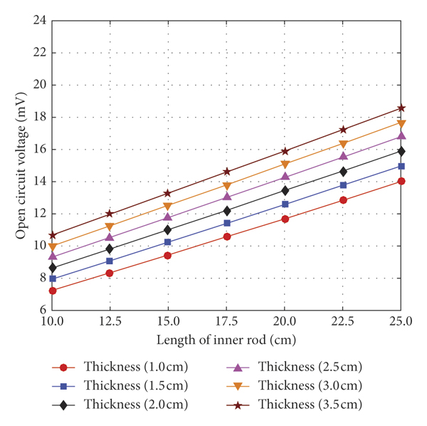
As shown in Figure 7, for a given D out (10.5 cm) and D in (3.2 cm), in theory, as L increases, the distance between the two magnetic poles gets further, making the demagnetization field weakened and the effective permeability increased significantly. When h increases, more magnetic flux can be guided into the core and the magnetic poles are formed at a further distance. It results in a decrease in the demagnetization field and an increase in the open circuit voltage. Thus, a longer inner rod and a pair of thicker magnetic flux collector plates can harvest more energy from the magnetic field. As shown in Figure 8, when h (2.5 cm) and L (23 cm) are given, as D out increases, more magnetic flux can be guided into the core and enable the distribution of surface magnetic poles to become more discrete, which results in a significant increase in the open circuit voltage. As D in decreases, the copper wire resistance becomes lower, leading to the increased output power. However, the volume of the I-shaped core increases significantly when a pair of bigger plates is used, which slowly increases the power density of the coil relative to the smaller plates. But the power density of the biggest plate remains the highest when D in is larger than about 2.3 cm, as the results are shown in Figure 9.
The open circuit voltage of the I-shaped coils with different lengths of the inner rod L as a function of the plate thickness h.
The output power of the I-shaped coils with different inner diameters D in as a function of the plate diameter D out.

The power density of the I-shaped coils with different inner diameters D in as a function of the plate diameter D out.

In summary, an I-shaped core which comprises a long and thin inner rod and a pair of thick and big magnetic collector plates can generate a greater output power. Keeping the h and L unchanged, a thinner inner rod which is above 2.3 cm and a pair of bigger plates can lead to an increase in both the output power and the power density.
2.3. Energy Harvester Design: Grid-Shaped
As shown in Figure 10, the field line (external magnetic flux) can be bent by high-permeability soft magnetic material. Although block (a) and block (b) have the same size, block (b) can guide more magnetic flux than block (a) due to its more discrete distribution. Block (b) and block (c) have the same sphere of guiding magnetic flux, but the volume of block (b) is smaller than that of block (c).
Schematic view of the field line bending by different sizes of high-permeability soft magnetic material. Volume (a) = volume (b) <volume (c).

Therefore, a more efficient grid-shaped energy harvester can be designed as shown in Figure 11. Compared with the I-shaped core shown in Figure 5(b), the magnetic collector plates of the grid-shaped core are hollow. Note that the grid-shaped core (a) and grid-shaped core (b) have the same outer diameter D out with the I-shaped core, respectively.
The grid-shaped core (a) has the same D out as the I-shaped core (D out = 10.5 cm, h = 2.5 cm, and W = 1 cm); the grid-shaped core (b) has the same volume as the I-shaped (D out = 18.5 cm, h = 2.5 cm, and W = 1 cm); (c) the schematic of the grid-shaped magnetic flux collector plate for both grid-shaped cores.

The grid-shaped coil is also simulated using CST EM Studio software. As depicted in Figure 12, the simulated environment is the same as the I-shaped coil described in Section 2.2. Due to that the hollow grid-shaped coil (a) has the same D out as the solid I-shaped coil, both of them have almost the same sphere of guiding magnetic flux, making them have almost the same open circuit voltage. However, the volume of grid-shaped coil (a) is smaller than that of the I-shaped coil. As a result, the power density of the grid-shaped coil (a) is 44% higher. The calculated result is shown in Figure 13. The hollow grid-shaped coil (b) has the same volume Vol as the solid I-shaped coil, but the magnetic collector plates of the grid-shaped coil (b) are bigger than those of the I-shaped coil, allowing more magnetic flux to be guided, and a larger open circuit voltage (1.6 times that of the I-shaped coil when μ r is 2000) can be acquired. As shown in Figure 13, the power density of the grid-shaped coil (b) can reach 2.6 times that of the I-shaped coil.
The simulated open circuit voltage of four coils when an external magnetic flux density of 6.5 μTrms is applied.

The calculated power density of four coils when an external magnetic density of 6.5μTrms is applied.

In summary, compared with the I-shaped coil, the weight of the grid-shaped coil is lighter and the power density is greater. If the I-shaped coil and the grid-shaped coil have the same weight (volume), the grid-shaped coil can guide more magnetic flux and achieve larger output power.
2.4. Core Material Selection
As seen in (2), the output power P depends on the open circuit voltage V coil and coil resistance R coil. V coil can be influenced by the core material on the effective permeability μ eff and the effective cross-sectional area A of the core. R coil can be influenced by core equivalent resistance R core.
The effective permeability of the core μ eff is plotted in Figure 14 as a function of the relative permeability. The effective permeability increases with the increase of the relative permeability. The two curves become saturated as μ r increased, and their knee point appears when μ r is about 300 and 1000 for the rod core and I-shaped core, respectively. As a consequence, μ r of the core material is at least approach 1000 which is more proper for the I-shaped core.
The effective permeability of two cores as a function of the relative permeability.

As a result of the skin effect occurred in the core and the magnetic flux tends to have a propagation along the surface of the path, it leads to reduced A. The skin depth can be derived as follows:

where ρ is the material resistivity of the core in Ωm, ω is the angular frequency of transmission line current in rad/s, μ 0 is the vacuum permeability which is equal to 4π × 10−7 H/m, and μ eff is the effective permeability. As shown in (6), a greater ρ leads to a deeper skin depth. The μ eff of the I-shaped core is about 100, and ω is set to 50 Hz. For the common soft magnetic material, ρ of iron-silicon alloy, amorphous and nanocrystalline alloy, nickel-iron alloy, and soft magnetic alloy material are all in the order of μΩm [31, 32]. Its maximum skin depth does not exceed 1 cm, which is less than the inner rod diameter D in for the I-shaped core, and the skin effect cannot be ignored. The Mn-Zn soft ferrite belongs to nonmetallic materials and has been used as magnetic material widely, its ρ is extremely higher than those of silicon steel and soft magnetic alloy (usually in the magnitude of Ωm [33]), and the skin depth is far above the inner rod diameter range. As a consequence, the D in can be considered as the diameter of the effective cross section and the skin effect can be ignored when we select Mn-Zn soft ferrite as core material. The following papers [Reference Van Schalkwyk and Hancke27–Reference Yuan, Huang, Zhou, Xu, Song and Yuan29] also used Mn-Zn cores for energy harvesting under power lines. In addition, the authors in [Reference Dyo, Ajmal, Allen, Jazani and Ivanov34, Reference Shirai, Mitamura and Arai35] used Mn-Zn for other energy harvesters.
For the core equivalent resistance R core, there are three losses occurring in the soft magnetic core when it is placed in the alternating magnetic field, including eddy current losses, hysteresis losses, and residual losses. When using the soft magnetic material with low coercivity, the hysteresis losses and residual losses can be ignored in this application as it is placed in the extremely low-power frequency (50 Hz) and very weak magnetic field (usually in the magnitude of μT). The eddy current losses are mainly considered here, and the power consumption of the eddy current losses can be derived as follows:

where S is the cross-sectional area in m2, ρ is the material resistivity of the core in Ωm, B in is the inner magnetic flux density of core in Trms, and k is the shape factor. When the I-shaped core is placed in an alternate magnetic field with 50 Hz, the W eddy is inversely proportional to ρ. For the I-shaped core, set μ r to be 2000, the material resistivity ρ is 1 μΩm (a typical value of ρ for the silicon steel and soft magnetic alloy material) and 6.5 Ωm (a typical value of ρ for the Mn-Zn soft ferrite), respectively. The simulation result of eddy current density in the cross section at the middle of I-shaped core is shown in Figure 15. At the edge of the core, the eddy current can be greater than 500 A/m2 in Figure 15(a) and lower than 0.006 A/m2 in Figure 15(b). The eddy current generates an opposite magnetic field which is against the external magnetic field and consumes electromagnetic energy in the form of heat. Compared with the ideal open circuit voltage V coil of 15.8 mV when the ρ is infinite (the conductivity is zero), the simulation shows that the V coil is reduced to 12.4 mV in Figure 15(a) but unchanged in Figure 15(b). As a consequence, the R core can be ignored when the Mn-Zn soft ferrite is selected.
The eddy current density inside the core when μ r = 2000. (a) The resistivity ρ is 1 μΩm and (b) the resistivity ρ is 6.5 Ωm.

In summary, the relative permeability of the Mn-Zn soft ferrite is about 2000 which is above the knee point of 1000, and the material resistivity is in the order of Ωm, and the skin effect and eddy current losses can be both ignored. Thus, the Mn-Zn soft ferrite is the most suitable material for the application and requirement.
3. Experiment Validations and Result
3.1. Experiment Setup
While the rod core and the I-shaped core can be easily obtained from some magnetic materials factory, the grid-shaped core cannot be easily fabricated as it needs to be mold and cut. In this experiment, the concept of the I-shaped core was demonstrated by testing the I-shaped core and the rod core.
A pair of Helmholtz coils as shown in Figure 16 is made to generate a uniform alternating electromagnetic field to imitate the electromagnetic environment near the power line. The diameter of the Helmholtz coil is 1 m, winding 30 turns of copper wire. With 120 mArms alternating current which is outputted by a function generator (RIGOL, DG4162) passing through the Helmholtz coil, a magnetic flux density of 6.5 μTrms can be generated.
A Helmholtz pair is made to generate a uniform alternating electromagnetic field in the laboratory.

The parameters of the rod core and I-shaped core are listed in Table 2. The rod core and a pair of magnetic collector plates are fabricated as shown in Figure 17. The I-shaped core can be combined with the rod core and plates. The dimensions of cores are the same as shown in Figure 5, and the Mn-Zn soft ferrite [36] is used as the core material (μ r is 2300 ± 25% and material resistivity is 6.5 Ωm).

Overview of the rod core, a pair of magnetic collector plates, and three spools with a winding number of 10000, 20000, and 20000 from left to right, respectively.

In order to wind wire conveniently, three same spools are introduced. Their winding numbers are 10000, 20000, and 20000, respectively. The diameter of the winding and the resistivity for the copper wire are 0.33 mm and 0.22 Ω/m, respectively. The dimensions of the spool are shown in Figure 17. The core can be inserted into the spool that has a different combination to get different winding numbers.
3.2. Experiment Validations and Result
Two cores with an increasing winding number are put into the Helmholtz coil and the open circuit voltage is measured with a multimeter. As shown in Figure 18, the measured voltage values are in good agreement with the theoretical ones, and the measured voltage of I-shaped is 2.7 times that of the rod. It is noted that the experiment results of the rod core are a little higher than the simulation values. This should be mainly caused by the initial winding diameter (4 cm) which is slightly larger than the diameter of the core (3.2 cm), leading to more magnetic flux through the spool. However, for the I-shaped core, the loss of the core is not considered during simulation, also the collector plates are not fully in contact with both ends of the rod, and there are air gaps in every contact surface of the I-shaped core, leading to a slight reduction in the overall effective permeability and the lowered measured voltage than theory.
The open circuit voltage of the two coils as a function of the winding number.

The copper resistance R copper can be considered as the coil resistance R coil when the Mn-Zn soft ferrite is used. In theory, the copper wire can be winded from the diameter of the rod (3 cm), and the interval length is the length of the rod (23 cm). However, in practice, the copper wire is winded from the outer diameter of the spool (4 cm), and the interval length is the inner length of the spool (9.6 cm), resulting in increased copper resistance. As shown in Figure 19, the winding number 30000 is combined with 10000-turn spool and 20000-turn spool. The winding number 40000 is combined with two same 20000-turn spools. As a result, the R copper is increased by 40.2%, 50.7%, 27.1%, and 20.7% for the winding number 10000, 20000, 30000, and 40000, respectively.
The copper resistance of the two coils as a function of the winding number.

The circuit with a compensating capacitor and a matched load is built to get the maximum output power for the harvesting coil. On the one hand, a perfect compensating capacitor could not be found in this experiment, which decreases the measured output power. On the other hand, from (2), the output power is directly proportional to the square of the open circuit voltage and is inversely proportional to the resistance of the coil. As shown in Figure 20, in this experiment, for the I-shaped core, the lower open circuit voltage and higher copper resistance relative to the theory can both reduce the output power. As a result, the output power reduces significantly. For the rod core, the higher open circuit voltage and higher copper resistance relative to the theory can offset the influence on the output power. It allows the measured output power to be in good agreement with the theoretical ones.
The output power of the two coils as a function of the winding number.

However, the output power of the I-shaped core is still higher than the conventional rod core. In this case, the measured output power of the I-shaped (4.5 mW) is 6.8 times that of the rod (665 μW) with 40000 turns. In addition, as shown in Figure 21, the power density of the I-shaped coil is 7.28 μW/cm3 with 40000 turns, which is double that of the rod coil under the same electromagnetic environment.
The power density of the two coils as a function of the winding number.

3.3. Circuit Design
In order to make the electromagnetic energy harvester drive a low energy load and verify the feature of self-powered I-shaped coil, as shown in Figure 22, a circuit [Reference Roscoe and Judd11, Reference Shirai, Mitamura and Arai35] is designed including storage circuit (part A), buffer circuit (part B), and load (part C).
Equivalent circuit of the complete free-standing electromagnetic energy harvester.

For the storage circuit (part A), C1 is the compensating capacitor, C2 is the storage capacitor (4700 μF), and D1 and D2 are the Schottky diodes, which constitute a double voltage rectification circuit. For the buffer circuit (part B), the Zener diode D3 provided a reference voltage to the negative input of the current comparator (LT1017). R2, R3, R4, R5, and R8 are reducing voltage resistors. R1, R6, and R7 are protecting resistors. Q1 and Q2 are MOSFET switches.
The test circuit is illustrated in Figure 23. The I-shaped coil with 40000 turns is used as the test harvester, and its maximum output power in the experiment is 4.5 mW. When the load is a high-power red LED light, it glowed periodically, the voltage of C2 increased from 2.1 V (U L) to 4.0 V (U H) after a period of 14 s, this corresponds to the energy E = 0.5C2 (UH 2 − HL 2) = 27.2 mJ, and the time of the light glowed is about 0.2 s. Thus, the average power delivered can be up to 136 mW. This design can be used to power sensors which require high operating power. When the load is another low-power red LED light, it kept glowing and the voltage of C2 stabilized in 4.0 V (U R) and the current of load stabilized in 0.6 mA (U R), which is shown in Figure 19. Thus, the consumed power of the LED light is 2.4 mW, and the efficiency of the whole circuit is around 53%.
The real test circuit designed to drive a low-power red LED light, the multimeters (a) and (b) were used to measure the voltage and current of LED, respectively.

4. Discussion and Application
In this experiment, the measured voltage values of the I-shaped coil are in good agreement with the simulated ones, which validate the conceptual model discussed in the previous section. The I-shaped coil with 40000 turns can collect a maximum output power of 4.5 mW when an external magnetic flux density reaches 6.5 μTrms, which might be enough to drive a small low-power wireless sensor continuously [37]. In the experiment, the magnetic field was generated by a Helmholtz coil. In order to ensure that the circuit will be in operation for practical applications, the generated field in the experiment is chosen to be slightly lower than the real ground magnetic field. If the harvested energy in the experiment is sufficient to power the device, in reality, the ground magnetic field is slightly stronger, and the harvested energy should be sufficient to power the same device. As the copper wires are winded from the outer diameter of the spool (4 cm) instead of the diameter of the rod (3 cm), there was an increase in the copper resistance and the actual output power reduced about 20%. But from another point of view, the I-shaped coil which combines with a pair of magnetic flux collector plates, a rod, and some spools is easier to make and assemble to meet the actual energy demand. The I-shaped core designed and tested in this paper is compared with several existing designs of electromagnetic energy harvesters and their key parameters including length, number of windings, wire diameter, magnetic flux density level, maximum output power, and power density are listed in Table 3.

We also carried out a test to estimate the sensitivity of our design to the physical rotation of the energy harvester against the power line. When the harvester was vertically rotated by 45°, the output voltage is dropped by 10%. The voltage is dropped by 75% when the harvester is vertically rotated by 90°. When the harvester is horizontally rotated by 45°, the output voltage is dropped by 10%. The voltage is dropped by 85% when the harvester is vertically rotated by 90°. It indicates that the harvester has a very stable performance against misalignment.
When the harvester is placed nearer or further away from the power line, the magnetic field density will be different, so the harvested power will be different as a result. Since the overhead power line is above the ground, the higher the energy harvester is placed above the ground, it implies that the energy harvester is closer to the power line; therefore, the magnetic field is higher. But usually, over the first couple of meters, the effect is relatively small. For example, for a standard overhead transmission power line (400 kV L12), the level of the magnetic field is assessed at 1 m/2 m above the ground and also at ground level in [39]. It can be seen that as the height increases from the ground level to 1 m and 2 m above the ground, the corresponding magnetic field is 5 μT, 6 μT, and 7 μT, respectively. The results in the paper are based on a magnetic field of 6.5 μT, which represents a location around 1.5 m above the ground. The harvested power at different distances from the power source/line is usually proportional to the square of the magnetic field level.
Therefore, in order to increase the output power, for the external condition, the I-shaped coil should be placed in a position closer to the power line or substation to increase the external magnetic flux density. The efficiency of the whole energy harvester circuit can be increased by selecting a more suitable load resistance [Reference Roscoe and Judd38]. As the free-standing I-shaped coil can be installed on the pylon, the weight and size of the harvester can be increased appropriately within a certain range. For the coil itself, a pair of bigger plates and a longer inner rod can reduce the demagnetization factor and increase the effective permeability significantly, and the number of winding for the spools and the number of the I-shaped coils can be both increased. In addition, multisource energy integration is another better way to power the sensor, and it can integrate electromagnetic energy and solar energy to achieve the complementary advantages of different energy sources, so that the supply can be more stable.
An example of an automatic weather station is considered, and it consists of three parts: sensors (80 mW), data collector (70 mW), and communication module (500 mW). Thus, its total required power is about 650 mW. If the I-shaped coil with 40000 turns which is tested in this experiment is placed 2 meters below the 400 KVrms, 500 Arms, L12 overhead power lines, the external magnetic flux density for the I-shaped coil can reach 20.5 μTrms and results in the maximum output power increasing to 44.8 mW. Therefore, the automatic weather station can work every 15 minutes if it takes a maximum of 1 minute to monitor, record, and send data.
The I-shaped coil was compared with other recently reported designs. Yuan et al. proposed two special designs of core shape including bow-tie shape and helical shape as listed in Table 3, and both of the designs were difficult to fabricate [Reference Yuan, Huang, Zhou, Xu, Song and Thompson28, Reference Yuan, Huang, Zhou, Xu, Song and Yuan29]. It was not easy to wind wires on the helical coil and the winding turns were limited by its structure. The maximum estimated output power of their helical core was 2.86 mW when it was placed in a magnetic flux density of 7 μTrms; the power density of the helical core was 9.8 μW/cm3. If the I-shaped coil designed in this paper is placed in the same external magnetic environment, the output power would be 5.2 mW and the power density would be 8.4 μW/cm3, which achieves a higher power and similar power density, and it can be more easily to fabricate and assemble. Compared to the I-shaped coil, a more high-efficiency grid-shaped coil is proposed. Its weight is lighter, but the amount of energy harvested is almost the same. If the I-shaped core is replaced by the grid-shaped core with the same weight, the power density can be increased by above 160% with simulated and reached 21.8 μW/cm3 by predicted when it is placed in a magnetic flux density of 7 μTrms, which is 2 times more than helical-shaped core design.
The life expectancy of batteries powering sensing systems becomes a bottleneck in many applications. Batteries often last for 3 years’ time. It is time-consuming and expensive to replace batteries manually for the entire network. The life expectancy of the proposed electromagnetic energy harvesters is much longer. Electromagnetic energy harvesters can work consistently in any weather conditions, and their life expectancy is up to 20 years.
5. Conclusions
In this paper, a new free-standing energy harvester is designed to scavenge the magnetic energy near power lines, substations, or other places with large alternating current. A free-standing energy harvester is different from the cable-clamped harvester. It does not need to be clamped to the power lines and can be easily assembled and installed.
The demagnetization factor cannot be ignored for a free-standing inductive coil. The conventional solenoid can only reduce the demagnetization factor by increasing the length-to-diameter ratio that occupies more space. Based on Faraday's law of magnetic induction and Gauss's law of magnetic field, an I-shaped core with added magnetic flux collector plates at both ends of the rod core is proposed, and it can guide more magnetic flux from big plates at both ends and reduce the demagnetization field at the middle of the I-shaped core. Through theoretical analysis, software simulation, and experimental verification, the inexpensive Mn-Zn ferrite with higher relative permeability and ultralow conductivity is considered as the most suitable material and is finally selected, and the eddy current loss in the core can be ignored.
From the experimental results, the output power of the I-shaped coil (4.5 mW) with 40000 turns is already greater than that of the rod coil (665 μW). The power density of the I-shaped coil is 7.28 μW/cm3, which is double that of the rod coil. A buffer circuit is utilized to power the sensors which require high operating power and work intermittently. It can provide a peak power of 136 mW for 0.2 s in a cycle or drive the load continuously at a power of 2.4 mW. Therefore, the proposed solution is very practical and inexpensive to supply condition monitoring sensors with magnetic field energy harvesting. The next phase of work will involve validating the grid-shaped coil and applying the magnetic energy harvester to a real overhead power line or substation to drive the condition monitoring sensor and verify its performance.
Data Availability
The data used to support the findings of this study can be made available upon request.
Conflicts of Interest
The authors declare that they have no conflicts of interest.
Acknowledgments
The authors would like to thank Jiafeng Zhou and Sheng Yuan from the University of Liverpool for very helpful advice and Guowei An from the Chengdu University of Information Technology for helpful editing. The authors would like to acknowledge the funding from the National Natural Science Foundation of China (41605122).


 Open access