


1. INTRODUCTION
A weapon Inertial Navigation System (INS) is a self-contained unit. Therefore, it is the most reliable source of navigation when the Global Navigation Satellite System (GNSS) and the other navigation aids become useless because of jamming or other reasons. However, the target strike precision is greatly dependent on the initialisation accuracy of the weapon INS. During the initialisation process, the Position, Velocity and Attitude (PVA) data are transferred from the aircraft INS to the weapon INS, the weapon velocity and attitude errors are estimated, and the weapon inertial sensors are calibrated. This process is defined as Transfer Alignment (TA). Errors in definition of the moment arm between the aircraft INS and the weapon INS degrade the initialisation performance. These errors have static and dynamic components. Static errors are generally caused by manufacturing tolerances and incorrect mounting of the weapon on the aircraft. On the other hand, dynamic errors result from flexures and vibrations of the aircraft structure, and become significant especially when the aircraft is manoeuvring. Since pre-determined aircraft manoeuvres are inevitably necessary to match or compare the aircraft and weapon inertial measurements during the TA process, taking into account the aircraft flexibilities and vibrations is expected to improve the initialisation accuracy.
The most popular and conventionally used TA method is known as the Velocity Match (VM). In this method, the aircraft is generally required to make a coordinated turn or an ‘S’ manoeuvre in a span of minutes in order to decrease the weapon attitude and inertial sensor errors to desired levels. TA with VM is acceptable for pre-planned operations, in which the pilot has enough time before launching the weapon. On the other hand, in the case of a target of opportunity, time is the most critical parameter and is limited to not more than 30 seconds. In that case, the Velocity and Attitude Match (VAM) method is preferred. TA with VAM can be done by using a Wing-Rock (WR) manoeuvre of the order of seconds, without changing the aircraft heading. The biggest restriction in using VAM is that the flexures between the weapon INS and the aircraft INS are needed to improve the TA performance. This requirement makes necessary either the constitution of an aircraft aeroelastic model or the measurement of flexures during flight.
Ways of treating the non-rigid aircraft in TA literature can be basically divided into three subgroups. The first subgroup of studies reported in the literature determines the in-flight flexible aircraft wing motion by using some sort of measurement technique (Li et al., Reference Li, Jiang and He2006; Lizotte and Lokos, Reference Lizotte and Lokos2005; Kaiser et al., Reference Kaiser, Beck and Berning1998; Lokos et al., Reference Lokos, Bahm and Heinle1995). The second subgroup models the flexibilities and/or vibrations of the aircraft wing stochastically (Xie et al., Reference Xie, Zhao and Yang2011; Xie et al., Reference Xie, Zhao and Wang2010; Groves and Haddock, Reference Groves and Haddock2001; Stovall, Reference Stovall1996; Graham and Shortelle, Reference Graham and Shortelle1995; Yang et al., Reference Yang, Lin, Tarrant, Roberts and Ruffin1993; Tarrant et al., Reference Tarrant, Roberts, Jones, Yang and Lin1993; Jones et al., Reference Jones, Roberts, Tarrant, Yang and Lin1993; Spalding, Reference Spalding1992; Pszczel and Bucco, Reference Pszczel and Bucco1992; Rogers, Reference Rogers1991; Kain and Clouter, Reference Kain and Cloutier1989; Schneider, Reference Schneider1983). The stochastic model approach is based on data recorded during the captive carry tests of the aircraft. However, since the flexures change depending on the payload, fuel level, speed and altitude of the aircraft, it is necessary to repeat the tests for all values of these parameters, which requires time and increased cost. The third subgroup of studies models the flexures as a linear function of aircraft specific forces (Groves et al., Reference Groves, Wilson and Mather2002; Kelley et al., Reference Kelley, Carlson and Berning1994; Carlson et al., Reference Carlson, Kelley and Berning1994). Groves et al. (Reference Groves, Wilson and Mather2002) related the angular flexures to aircraft specific forces, but they had to insert six additional states into the Kalman Filter (KF) in order to define the angular flexures. Kelley et al. (Reference Kelley, Carlson and Berning1994) and Carlson et al. (Reference Carlson, Kelley and Berning1994) structured their flexure models based on the specific force-dependent flexure angles. They employed stochastic methods to establish flexure-specific force relationships.
The objective of this paper is to develop a new TA method which meets the following expectations:
• The developed method should improve the INS initialisation performance and the target strike precision compared to TA methods such as VM or VAM with stochastic flexibility models.
• It should not require captive carry tests for determination of flexures.
• It should run on the weapon mission computer in real-time.
• It should not increase the size of the problem.
The method developed in this paper relates the flexures to specific forces as in the third subgroup of papers above. However, differently from the previous studies, neither stochastic methods nor an increased order KF are employed, and a completely deterministic approach is used to define the flexures. Accordingly, flexures are obtained by analysing the aircraft model using MSC Nastran™ (NAsa STress ANalysis Program), which is a finite element analysis program that performs static aeroelastic, dynamic aeroelastic or flutter analysis of structures. The MSC Nastran™ aircraft model had been previously verified by ground vibration tests such that the model and test natural frequencies of the aircraft structure are sufficiently close to each other. A linearised KF is used to estimate the errors by processing the noisy measurements. Comparisons are made based on the Standard Deviations (SDs) of error terms and Circular Error Probable (CEP) values for VM and VAM.
2. THEORY – TRANSFER ALIGNMENT SIMULATION ENVIRONMENT
In order to run the TA algorithm on a stand-alone computer, it is necessary to generate a simulation environment reflecting the real flight conditions as nearly as possible. A block diagram of the simulation environment considered in this study is shown in Figure 1.
TA simulation environment.

Equations describing each block in Figure 1 were previously derived (Pehlivanoğlu, Reference Pehlivanoğlu2009). A brief explanation of each block will be given in the following sections. Block labels such as A, B, C, … and the section numbers related to each block are also given in Figure 1 in order to increase traceability.
2.1. Aircraft Trajectory Shaping (Block A)
This module generates the Euler angles, and their first and second derivatives from the roll angle variations and velocity of the aircraft during the manoeuvre (Musick, Reference Musick1976). The Euler angle variations of an aircraft, travelling at 301 m/s, are shown in Figure 2 for a 34-degree WR manoeuvre with a duration of 23 s. φ, θ and ψ in Figure 2 stand for roll, pitch and yaw Euler angles respectively.
Aircraft Euler angles.

2.2. Aircraft Trajectory Generator (Block B)
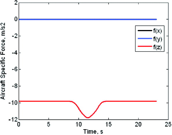
Based on the initial position and velocity of the aircraft as well as the Euler angles and their derivatives obtained from the Aircraft Trajectory Shaping Module (Block A), this module generates the reference (errorless) values of PVA for the aircraft INS, and the reference values of specific force and angular velocity for the aircraft Inertial Measurement Unit (IMU). The first derivative of the angular velocity, which is necessary for the moment arm compensation, is also calculated by this module. f(x), f(y) and f(z) in Figure 3 are specific force components of the aircraft.
Specific forces of the aircraft.
2.3. Flexure and Vibration Models (Block C)
This module provides flexure and vibration values at the weapon INS location during the manoeuvre. The calculation and inclusion of flexures deterministically in the TA algorithm is the main novelty of the study.
The aircraft INS is on the main body of the aircraft, while the weapon INS is under the wing. For such a configuration, aircraft and weapon INSs are subjected to rigid body motion as well as elastic body motion. Rigid body motion represents the movements that the aircraft makes as a rigid structure. As a result, there is no relative motion in the body frame between any two arbitrary points on the aircraft. Elastic body motion results from the structural flexures and vibrations. In this case, there is a relative motion in the body frame between the points on the aircraft. Flexure defines the low-frequency and high-amplitude motion due to the elastic deformation of the aircraft structure. On the other hand, vibration represents the high-frequency and low-amplitude motion induced by forces from the environment. Flexures and vibrations can be present along and around any axis of a Cartesian coordinate frame in three dimensional space.
The errorless moment arm and attitude between the aircraft and weapon INSs can be represented by Equation (1) and Equation (2) respectively as:
 $$r = r_{stat} + r_{dyn} $$
 $$e = e_{stat} + e_{dyn} $$
with:
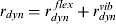 $$r_{dyn} = r_{dyn}^{\ flex} + r_{dyn}^{vib} $$
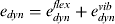 $$e_{dyn} = e_{dyn}^{flex} + e_{dyn}^{vib} $$
where:
r is the errorless moment arm vector between the aircraft and weapon INSs.
r stat is the static or invariant component of the moment arm vector.
r dyn is the dynamic or time-variant component of the moment arm vector.
r dynflex is the component of r dyn due to low-frequency and high-amplitude flexure motion.
r dynvib is the component of r dyn due to high-frequency and low-amplitude vibration motion.
e is the errorless attitude vector between the aircraft and weapon INSs.
e stat, edyn, edynflex and e dynvib have definitions in parallel to those of r stat, rdyn, rdynflex and r dynvib.
2.3.1. Flexure Model
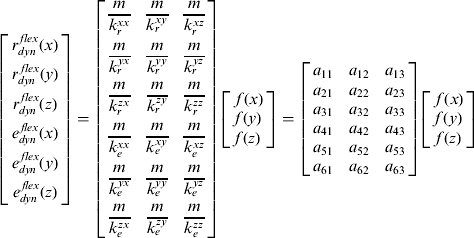
This module calculates the linear and angular flexure components r dynflex and e dynflex in Equation (3) and Equation (4). A linear approach is used for this model. That is, the flexures are proportional to the forces, which occur as a result of the input applied by the pilot to the control stick. In that case, the flexures are obtained by multiplying the forces by certain coefficients. The linear relationship between the specific forces measured by the aircraft IMU and the flexures is given by Equation (5).
 $$\left[ \openup3\matrix{r_{dyn}^{\,flex} (x) \cr r_{dyn}^{\; flex} (y) \cr r_{dyn}^{\,flex} (z) \cr e_{dyn}^{\,flex} (x) \cr e_{dyn}^{\,flex} (y) \cr e_{dyn}^{\,flex} (z)} \right] = \left[ {\openup4\matrix{ {\displaystyle{m \over {k_r^{xx}}}} & {\displaystyle{m \over {k_r^{xy}}}} & {\displaystyle{m \over {k_r^{xz}}}} \cr {\displaystyle{m \over {k_r^{yx}}}} & {\displaystyle{m \over {k_r^{yy}}}} & {\displaystyle{m \over {k_r^{yz}}}} \cr {\displaystyle{m \over {k_r^{zx}}}} & {\displaystyle{m \over {k_r^{zy}}}} & {\displaystyle{m \over {k_r^{zz}}}} \cr {\displaystyle{m \over {k_e^{xx}}}} & {\displaystyle{m \over {k_e^{xy}}}} & {\displaystyle{m \over {k_e^{xz}}}} \cr {\displaystyle{m \over {k_e^{yx}}}} & {\displaystyle{m \over {k_e^{yy}}}} & {\displaystyle{m \over {k_e^{yz}}}} \cr {\displaystyle{m \over {k_e^{zx}}}} & {\displaystyle{m \over {k_e^{zy}}}} & {\displaystyle{m \over {k_e^{zz}}}} \cr}} \right]\left[ \matrix{\,f(x) \cr f(y) \cr f(z)} \right] = \left[ {\matrix{ {a_{11}} & {a_{12}} & {a_{13}} \cr {a_{21}} & {a_{22}} & {a_{23}} \cr {a_{31}} & {a_{32}} & {a_{33}} \cr {a_{41}} & {a_{42}} & {a_{43}} \cr {a_{51}} & {a_{52}} & {a_{53}} \cr {a_{61}} & {a_{62}} & {a_{63}} \cr}} \right]\left[ \matrix{\,f(x) \cr f(y) \cr f(z)} \right]$$
where:
f's are the specific forces.
m is the total aircraft mass.
k r's and k e's are the influence coefficients for the linear and angular stiffnesses respectively.
The purpose of the flexure model is to calculate the coefficients a 11, a 12, a 13, a 21,… in Equation (5). This is done by using the aircraft specific force values, which are the user-defined inputs to the MSC Nastran™, along with the linear and angular flexure values, which are the outputs of the same program. These coefficients are calculated for a specific payload, fuel level, speed and altitude combination of the aircraft. Then the flexures can be obtained at any time during the real-time flight by using Equation (5) since the aircraft specific forces are known during the flight.
The coefficients in Equation (5) are not constants, because m changes due to the fuel consumption and the release of payloads. A database can be generated by determining the a 11, a 12, a 13, a 21, … coefficients for different fuel and payload conditions of the aircraft. Therefore, the necessary coefficients at any time during TA can be found by interpolation.
Both k r's and k e's in Equation (5) have two parts; namely, a term related to the rigidity of the structure, which is independent of the flight conditions, and a term which needs to be calculated for each flight condition specifically (i.e., for each Mach number and altitude). In other words, a database can be constituted depending on the Mach number and altitude, and the necessary coefficients can be determined by interpolation for any instantaneous Mach number and altitude during the flight.
Figure 4 depicts the flexure variations of the aircraft during the WR manoeuvre. In this case, the highest linear flexure component is in the normal direction with a magnitude of 30 mm. There is almost no linear flexure in the longitudinal direction, and a linear flexure of 10 mm in the lateral direction.
Linear and angular flexure variations.

2.3.2. Vibration Model
The linear and angular vibration components, which are r dynvib and e dynvib in Equation (3) and Equation (4), as well as their necessary derivatives, are assumed to be white noise in this study. This module calculates the variance values of these vibration noise terms. First, the related data recorded during captive flight tests are filtered by using a sharp high-pass filter. Then, the Power Spectral Densities (PSDs) of these data are calculated after elimination of the constant biases in the data. Areas under the PSD curves give the variance values of the related variables. 1σ SDs of the vibration noise terms are given in Table 1 for the aircraft considered in this study. 1σ SD of the position variation in the normal direction due to vibration is about 3·4 mm, while the longitudinal and lateral components are 1·1 mm and 1·8 mm respectively.
1σ SDs of the terms with vibration noise.
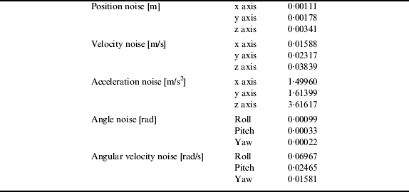
The ratio of the linear flexure component in Figure 4 to the position noise component in Table 1 in the normal direction is about 9, which is quite high. If the flexure variations are not known deterministically during the flight, sufficient noise needs to be injected into the TA KF based on past flight test experience, in order to take into account the flexure effect.
2.4. Rigid and Non-Rigid Moment Arm Effects (Block D)
This module calculates the errorless values of PVA, specific force and angular velocity of the weapon. Errorless PVA, specific force and angular velocity of the aircraft are provided by the Aircraft Trajectory Generator Module (Block B). Moreover, the contributions of flexure and vibration to the moment arm and attitude between the aircraft and weapon INSs are generated by the Flexure and Vibration Models Module (Block C). The errorless moment arm and relative orientation used in this module for the moment arm compensation are calculated by using Equation (1) and Equation (2) respectively.
2.5. Weapon IMU Errors (Block E)
This module generates the velocity and angle error increments for the weapon IMU by adding the sensor errors to the related errorless weapon outputs obtained from the Rigid and Non-Rigid Moment Arm Effects Module (Block D). Sensor errors are given in Table 2 for a typical low-cost weapon IMU.
Sensor errors.

2.6. Weapon INS Outputs (Block F)
This module generates the PVA error of the weapon by using the velocity and angle error increments provided by the Weapon IMU Errors Module (Block E) and the initial PVA error provided by the Moment Arm Compensation Module (Block H).
2.7. Aircraft INS Errors (Block G)
This module generates the aircraft velocity, attitude and angular velocity error values by adding the aircraft INS errors to the errorless aircraft velocity, attitude and angular velocity values calculated by the Aircraft Trajectory Generator Module (Block B).
1σ SDs of the aircraft velocity, attitude and angular velocity errors are 0·05 m/s, 3·4907 × 10−4 rad and 1·7453 × 10−4 rad/s respectively.
2.8. Moment Arm Compensation (Block H)
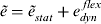
This module compensates the moment arm for the aircraft INS error outputs provided by the Aircraft INS Errors Module (Block G). It utilises the moment arm and relative orientation errors. In this module, it is assumed that:
 $$\tilde r = \tilde r_{stat}^{} + r_{dyn}^{\,\,flex} $$
 $$\tilde e = \tilde e_{stat}^{} + e_{dyn}^{\,\,flex} $$
where ˜ indicates that the variable under this accent contains error.
1σ SDs of the errors in  $$\tilde r_{stat}^{} $$ are 15 cm, 15 cm and 30 cm along the longitudinal, lateral and normal directions of the aircraft respectively. Similarly, 1σ SDs of the errors in
  $$\tilde e_{stat}^{} $$ are 20 mrad, 20 mrad and 10 mrad around the roll, pitch and yaw directions of the aircraft respectively.
The output of this module is the PVA error at the weapon INS location. Initial values of the PVA error are also supplied to the Weapon INS Outputs Module (Block F) to start the PVA calculation process of the weapon INS.
2.9. Measurement (Block I)
This module generates the KF measurements by taking the differences between the velocity/attitude error outputs provided by the Weapon INS Outputs Module (Block F) and Moment Arm Compensation Module (Block H).
2.10. TA Filter (Block J)
By using the measurements calculated by the Measurement Module (Block I), this module estimates the errors in weapon velocity, weapon attitude, weapon sensor repeatability, weapon sensor scale factor, static moment arm and static relative orientation using a KF. It also calculates the SDs of these states during the TA manoeuvre and feeds the error estimations back to the related variables to correct them in a closed-loop cycle with a period of 1 s. The structure of the KF is shown in Figure 5 (Brown and Hwang, Reference Brown and Hwang1997, p216, 219).
The KF structure.

In Figure 5, k refers to the k th loop, x is the state vector, Φ is the state transition matrix, P is the state covariance matrix, Q is the system noise covariance matrix, K is the gain matrix, H is the measurement matrix, R is the measurement noise covariance matrix, z is the measurement vector and I is the identity matrix.
3. SIMULATIONS
TA simulation results are presented in this section for a WR manoeuvre lasting 23 s, which is performed at 5000 ft (1524 m) altitude and 0·9 Mach velocity. This manoeuvre is especially suitable for the fast TA used in target of opportunity missions as it requires only a rapid roll around the aircraft's longitudinal axis followed by a roll back. This low altitude and high speed manoeuvre is quite severe for the generation of flexures and vibrations. The simulation code was developed by using MATLAB™ software and verified by Monte Carlo analysis (Pehlivanoğlu, Reference Pehlivanoğlu2009).
Two analyses were conducted in this study. In the first analysis, VAM was chosen as the TA method, and two different flexure models (i.e., deterministic (D) and noise (N) models) were used. This analysis was performed to show the advantage of modelling the aircraft flexures deterministically compared to modelling it as noise. In the second analysis, the flexure model was taken as deterministic, and two TA methods, namely VM and VAM were used. The aim of the second analysis was to show the advantage of VAM compared to VM. Results of the two analyses, which are given in the following sections, were compared based on the SD variations of the errors and the CEP variations of the weapon.
3.1. Analysis 1-TA Method: VAM, Flexure Model: Deterministic or Noise
In this analysis, in order to model the flexures as noise, noise SDs were calculated based on the mean values and SDs of the deterministically obtained flexures. Therefore, a good approximation was made for the noise model. On the other hand, determination of the noise SDs for real missions is not feasible because if one has deterministic flexures, it is not meaningful to calculate the noise SDs by using these flexures. The correct approach is to use the flexures directly.
The SDs of weapon north velocity, yaw attitude, x-accelerometer bias repeatability and x-gyroscope drift repeatability errors are shown in Figure 6 and Figure 7 as sample outputs of the analysis.
SDs of north velocity and yaw attitude errors of the weapon for the cases of VAM where flexures are modelled as deterministic and as noise.

SDs of x-accelerometer bias and x-gyroscope drift repeatability errors of the weapon for the cases of VAM where flexures are modelled as deterministic and as noise.

Modelling the flexures deterministically results in a 121·7% decrease in SD of the weapon yaw attitude error at the end of the manoeuvre as shown in Figure 6. In fact, this decrease occurs shortly after the WR manoeuvre and stays almost constant for the rest of the time. Estimation of the gyroscope drift repeatability error in the x-direction is almost not possible for the case of noise modelling as shown in Figure 7. On the other hand, modelling the flexures deterministically improves the SD estimation by 147·5%. As a result, one can conclude that the deterministic modelling of flexures improves both the SD estimation time and the accuracies of all error states estimated by the KF.
In order to make the above results more understandable, CEP values of the weapon after its release were calculated by using the SD values at the end of the TA manoeuvre. The results shown in Figure 8 indicate that the CEP value of the weapon is improved by 7·2% at 50 s after the weapon release if the flexures are modelled deterministically.
CEP values for the cases of VAM where flexures are modelled as deterministic and as noise.

3.2. Analysis 2-TA Method: VM or VAM, Flexure Model: Deterministic
VM can be preferred if there is not a requirement for fast initialisation of the weapon INS, because it is simpler, and does not require the use of deterministic flexures. A reasonably good approximation of the vibration noise based on past tests gives satisfactory results. On the other hand, VAM is more attractive when fast TA is needed (i.e., if the weapon is to be used against a target of opportunity). These targets require fast action; therefore, the long manoeuvre time needed for VM is not suitable for them.
The SD variations of weapon east velocity, yaw attitude, x-accelerometer bias repeatability and y-gyroscope drift repeatability errors are shown in Figure 9 and Figure 10 as sample outputs of the analysis.
SDs of east velocity and yaw attitude errors of the weapon for the cases of VM and VAM where flexures are modelled as deterministic.

SDs of x-accelerometer bias and y-gyroscope drift repeatability errors of the weapon for the cases of VM and VAM where flexures are modelled as deterministic.

The SD of weapon yaw attitude error decreases by 455·9% for VAM compared to VM at the end of the WR manoeuvre as shown in Figure 9. The x-accelerometer bias repeatability error cannot be estimated at all by VM, whereas it can be estimated quite quickly by VAM, with an improvement of 238·5% as shown in Figure 10. The SD of y-gyroscope drift repeatability error is also improved by 204·3%.
The computer used in the above calculations had an Intel Core 2 Duo-T7200-2 GHz CPU and a 1 GB RAM. Calculation times for the cases of VM and VAM using the deterministic flexure model were 11·5 s and 12·2 s respectively. Since these calculation times are significantly shorter that the manoeuvre duration, and the weapon mission computer has a better configuration, the developed code is also expected to run in real-time.
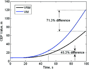
CEP values of the weapon are shown in Figure 11. CEP value at 50 s after the weapon release is improved by 45·3% by VAM as compared to VM. The improvement after 100 s is 71·3%.
CEP values for the cases of VM and VAM where flexures are modelled as deterministic.
4. CONCLUSIONS
The main objective of this paper was to improve the Transfer Alignment (TA) performance; that is, to obtain lower estimation errors at the end of a pre-planned TA manoeuvre. This objective was achieved by calculating the aircraft flexures deterministically and importing them into the TA algorithm in a novel approach, without using stochastic methods or increasing the order of the Kalman Filter (KF). The new method utilises a MSC Nastran™ aircraft aeroelastic model which was previously verified by ground vibration tests. The main advantage of using a computer model is that a database containing flexure variations for different payload, fuel level, speed and altitude conditions can be easily established, and used during the real mission. Moreover a computer program enables us to model any military aircraft for determination of flexures without any need for time-consuming and expensive captive carry tests.
In order to show the advantage of modelling the aircraft flexures deterministically compared to modelling them as noise, simulations were carried out by using the two approaches with Velocity and Attitude Match (VAM). The results for a Wing-Rock (WR) manoeuvre of 23 s showed that modelling the flexures deterministically reduces the Standard Deviations (SD) of errors by up to 147·5% and shortens the estimation time. The results also showed that the Circular Error Probable (CEP) values after a free flight time of 50 s following the weapon release is improved by 7·2% if the flexures are modelled deterministically.
Although the developed method is applicable to both VAM and Velocity Match (VM), incorporation of aircraft flexures deterministically improves the TA performance very significantly if VAM is used. Simulation results for a WR manoeuvre lasting 23 s indicated that the SDs of errors at the end of the manoeuvre were reduced by up to 456% for VAM as compared to VM. The results showed that the attitude errors reached to 10% band around their final values only after 7 s following the start of the WR manoeuvre. As a result, a manoeuvre time shorter than 23 s may also give satisfactory results. The final CEP value for the VAM was improved by 45% after a 50 s free flight time following the weapon release, and by 71% after 100 s as compared to the VM.
Incorporation of deterministically determined aircraft flexures to VAM allows the use of a short-duration TA manoeuvre such as WR. The calculation time of the developed method was achieved in approximately half the manoeuvre time, showing that the developed code can run in real-time. As a result, the developed method can be used for target of opportunity missions.
It should be noted that the aircraft used in the study was quite stiff, and it had a maximum flexure of only 30 mm in the normal direction even during such a strenuous low altitude (5000 ft, 1524 m) and high velocity (0·9 Mach) manoeuvre. Therefore, if the developed method is applied to lighter and more flexible aircrafts, the improvements in the results should be more remarkable.
Although the developed algorithm was verified by Monte Carlo analysis and the MSC Nastran™ model was updated by means of ground vibration tests, confirmation of the obtained results by captive carry and/or launch tests will be a good future development of the paper. A more flexible aircraft may also be studied in the future to demonstrate the effect of flexibility more clearly. Measurement of flexures for one or two flight conditions and comparison of the results with the MSC Nastran™ outputs will also increase the reliability of the new method.
ACKNOWLEDGEMENTS
The authors would like to thank to Mr. Mutlu D. Cömert for his encouragement to conduct this study, Mr. Erdinç N. Yıldız for construction of the aircraft aeroelastic model, Mr. Tolga Sönmez for his comments on the results, and Mr. Nicholas Lynch for his review and corrections.



