


Impact Statement
Understanding turbulent TC flow at ultra-high rotation speed and extremely narrow gaps is vital for optimising performance, efficiency and cooling strategies in advanced rotating machines. The novel NPU-TC apparatus provides unprecedented experimental capability to probe these challenging flow regimes, delivering comprehensive and high-resolution velocity data. This research addresses critical knowledge gaps regarding boundary layer dynamics, momentum transport and turbulence structures in extreme TC flow conditions, potentially guiding future design improvements in high-performance electric motors and generators.
1. Introduction
Rotating electric machines are devices that use electromagnetic forces to convert energy between electrical and mechanical forms. These machines are widely used in modern industry and are responsible for more than half of the total electricity consumption in several developed countries (Mecrow & Jack Reference Mecrow and Jack2008). As industrial technologies continue to advance, there is a growing need for machines that can operate at higher rotational speeds. This demand arises in many fields, such as in large asynchronous motors for heavy-duty applications, faster propulsion systems for ships and high-performance electric motors for electric vehicles (Patyk Reference Patyk2013). A typical rotating electric machine has two main components. The stator is located on the outside, and the rotor is located on the inside and both are arranged in a circular coaxial configuration. These components are separated by a narrow annular air gap. Their relative rotation produces strong azimuthal shear in this confined region. Viscous dissipation and heat generation are therefore concentrated in the gap. In many high-speed machines, thermal management relies on forced air cooling. In this approach, air is driven axially through the rotor stator gap while the rotor rotates at high speed. As designs evolve toward smaller size and higher power density, the flow in this narrow region becomes increasingly important. It affects how well heat is removed from the system, how much energy is lost due to friction and how reliable the machine is over time (Gronwald & Kern Reference Gronwald and Kern2021; Leung et al. Reference Leung, Lee and Probert1995).
The flow in the narrow gap between two rotating concentric cylinders can be idealised as a Taylor–Couette (TC) flow, a well-known model in fluid mechanics (Taylor Reference Taylor1923). When a pressure-driven mean axial flow is superposed, the configuration is commonly referred to as Taylor–Couette–Poiseuille (TCP) flow (or TC flow with imposed axial flow). The imposed axial flow breaks the purely rotational symmetry. It can advect, tilt or reorganise roll structures such as Taylor vortices and spiral vortices. It can also modify large-scale coherence and near-wall transport processes (Lueptow et al. Reference Lueptow, Docter and Min1992; Manna & Vacca Reference Manna and Vacca2009; Wereley & Lueptow Reference Wereley and Lueptow1999). Because axial flow is intrinsic to air-cooling strategies in rotating machinery, understanding TC turbulence under imposed axial flow is essential for connecting laboratory TC studies to machine relevant conditions.
Realistic operating conditions for high-speed air cooled machines correspond to an extreme TC and TCP regime. They involve very high rotation rates, typically
 $\ge 10\,000$
rpm, together with ultra narrow gaps. These features imply very strong shear and intense turbulence (Grossmann et al. Reference Grossmann, Lohse and Sun2016). Studying this parameter range in laboratory experiments is technically challenging. Because the gap between the cylinders is so narrow, the stator and rotor must be aligned with great precision to avoid mechanical contact or measurement errors. At the same time, the high rotational speeds require the entire system to be very stable and mechanically robust, which increases the complexity and cost of the set-up. Moreover, reproducing axial air cooling requires controlled axial flow through the annulus, which is typically not available in TC facilities. To our knowledge, no existing facility simultaneously achieves extreme rotation rates and ultra-narrow gaps while also enabling controlled axial flow through the gap.
$\ge 10\,000$
rpm, together with ultra narrow gaps. These features imply very strong shear and intense turbulence (Grossmann et al. Reference Grossmann, Lohse and Sun2016). Studying this parameter range in laboratory experiments is technically challenging. Because the gap between the cylinders is so narrow, the stator and rotor must be aligned with great precision to avoid mechanical contact or measurement errors. At the same time, the high rotational speeds require the entire system to be very stable and mechanically robust, which increases the complexity and cost of the set-up. Moreover, reproducing axial air cooling requires controlled axial flow through the annulus, which is typically not available in TC facilities. To our knowledge, no existing facility simultaneously achieves extreme rotation rates and ultra-narrow gaps while also enabling controlled axial flow through the gap.
To directly study the flow under extreme operational conditions of high-speed rotating machinery, we have designed and constructed a new TC flow apparatus, the Northwestern Polytechnical University Taylor–Couette (NPU-TC) set-up. The NPU-TC reaches inner-cylinder rotation rates of up to 10 000 rpm with a gap width of 2.8 mm. Air is used as the working fluid. This choice is directly relevant to air cooled machines. It also reduces the required driving torque and mechanical loading at very high rotation rates because of the low density compared with typical liquid working fluids. A key feature of the apparatus is the capability to impose a controlled axial flow through the annulus. The accessible range of axial flow velocity
 $(U_a)$
is 0–10 ms−1. This reproduces the essential topology of axial air cooling in rotor stator gaps. The facility therefore provides a platform for systematic studies of TC turbulence under imposed axial flow.
$(U_a)$
is 0–10 ms−1. This reproduces the essential topology of axial air cooling in rotor stator gaps. The facility therefore provides a platform for systematic studies of TC turbulence under imposed axial flow.
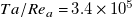
Table 1 provides a summary of representative experimental set-ups reported in the literature. In this table,
 $\eta =r_i/r_o$
denotes the radius ratio between the inner and outer cylinders, which is a dimensionless number that characterises the geometry of the system. The symbol
$\eta =r_i/r_o$
denotes the radius ratio between the inner and outer cylinders, which is a dimensionless number that characterises the geometry of the system. The symbol
 $\omega _{i, max}$
refers to the highest rotation rate of the inner cylinder in the presence of the working fluid. Avila and Hof (Reference Avila and Hof2013) constructed a highly precise TC apparatus using silicone oil as the working fluid, capable of reaching a maximum speed of 1800 rpm. Zhu et al. (Reference Zhu, Ji, Lou and Qian2018) measured torque and verified the ultimate turbulent regime in a system operating up to approximately 4500 rpm with both water and silicone oil. Despite these efforts, none of the existing systems are able to reach the benchmark of 10 000 rpm, which is representative of modern high-speed rotating machinery. Previous studies have also shown that investigations of momentum transport and flow evolution in TC turbulence are more feasible in systems with wider gaps. Such configurations simplify the mechanical design and facilitate the use of diagnostic techniques such as hot-wire probes, laser Doppler anemometry (LDA) and particle image velocimetry (PIV). In the Texas–Maryland Taylor–Couette (T-M TC) facility, Lathrop et al. (Reference Lathrop, Fineberg and Swinney1992) measured the scaling relationship between torque and Reynolds number (
$\omega _{i, max}$
refers to the highest rotation rate of the inner cylinder in the presence of the working fluid. Avila and Hof (Reference Avila and Hof2013) constructed a highly precise TC apparatus using silicone oil as the working fluid, capable of reaching a maximum speed of 1800 rpm. Zhu et al. (Reference Zhu, Ji, Lou and Qian2018) measured torque and verified the ultimate turbulent regime in a system operating up to approximately 4500 rpm with both water and silicone oil. Despite these efforts, none of the existing systems are able to reach the benchmark of 10 000 rpm, which is representative of modern high-speed rotating machinery. Previous studies have also shown that investigations of momentum transport and flow evolution in TC turbulence are more feasible in systems with wider gaps. Such configurations simplify the mechanical design and facilitate the use of diagnostic techniques such as hot-wire probes, laser Doppler anemometry (LDA) and particle image velocimetry (PIV). In the Texas–Maryland Taylor–Couette (T-M TC) facility, Lathrop et al. (Reference Lathrop, Fineberg and Swinney1992) measured the scaling relationship between torque and Reynolds number (
 $Re$
) at a radius ratio of
$Re$
) at a radius ratio of
 $\eta$
= 0.725. van Gils et al. (Reference van Gils, Bruggert, Lathrop, Sun and Lohse2011) obtained velocity profiles using LDA techniques in the Twente Turbulent Taylor–Couette (T
$\eta$
= 0.725. van Gils et al. (Reference van Gils, Bruggert, Lathrop, Sun and Lohse2011) obtained velocity profiles using LDA techniques in the Twente Turbulent Taylor–Couette (T
 $^3$
C) facility, with radius ratios ranging from
$^3$
C) facility, with radius ratios ranging from
 $\eta$
= 0.716 to 0.909. In the boiling Twente Taylor-Couette (BTTC) facility at the University of Twente, Huisman et al. (Reference Huisman, van der Veen, Bruggert, Lohse and Sun2015) measured both the torque and velocity fields in a TC system filled with water, at a radius ratio of
$\eta$
= 0.716 to 0.909. In the boiling Twente Taylor-Couette (BTTC) facility at the University of Twente, Huisman et al. (Reference Huisman, van der Veen, Bruggert, Lohse and Sun2015) measured both the torque and velocity fields in a TC system filled with water, at a radius ratio of
 $\eta = 0.714$
, using torque sensors and PIV, respectively. Butcher et al. (Reference Butcher, Barros, Higashi, Ng, Meuel, Gioia and Chakraborty2024) used water as the working fluid and measured the flow velocity using a flying hot-wire system in the Okinawa Institute of Science and Technology – Taylor–Couette set-up (OIST-TC) apparatus at a radius ratio of
$\eta = 0.714$
, using torque sensors and PIV, respectively. Butcher et al. (Reference Butcher, Barros, Higashi, Ng, Meuel, Gioia and Chakraborty2024) used water as the working fluid and measured the flow velocity using a flying hot-wire system in the Okinawa Institute of Science and Technology – Taylor–Couette set-up (OIST-TC) apparatus at a radius ratio of
 $\eta = 0.747$
. Overall, most facilities are limited either by maximum rotation rate or by the need for comparatively wide gaps. In addition, controlled axial flow is generally not available in high
$\eta = 0.747$
. Overall, most facilities are limited either by maximum rotation rate or by the need for comparatively wide gaps. In addition, controlled axial flow is generally not available in high
 $\eta$
and high-speed configurations.
$\eta$
and high-speed configurations.
Representative TC experimental systems: the radius of the inner cylinder
 $r_i$
, the operating radius ratios
$r_i$
, the operating radius ratios
 $\eta$
and the corresponding maximum inner-cylinder rotation rates
$\eta$
and the corresponding maximum inner-cylinder rotation rates
 $\omega _{i, max}$
. Here,
$\omega _{i, max}$
. Here,
 $r_o$
is the inner radius of outer cylinder
$r_o$
is the inner radius of outer cylinder

The TC (TCP) flow dynamics is described by dimensionless control parameters. In this work, the geometry is characterised by
 $\eta$
, and the driving is quantified primarily by Reynolds numbers based on the inner-cylinder rotation and imposed axial flow
$\eta$
, and the driving is quantified primarily by Reynolds numbers based on the inner-cylinder rotation and imposed axial flow
 \begin{equation*} Re=\frac {\omega _i r_i d}{\nu }, \qquad Re_a=\frac {U_a d}{\nu }, \end{equation*}
where
 $\omega _i$
is the inner-cylinder angular velocity,
$\omega _i$
is the inner-cylinder angular velocity,
 $U_a$
is the imposed mean axial velocity and
$U_a$
is the imposed mean axial velocity and
 $\nu$
is the kinematic viscosity. For comparison with prior TC studies, we also report the Taylor number
$\nu$
is the kinematic viscosity. For comparison with prior TC studies, we also report the Taylor number
 $Ta$
, which can be uniquely determined by
$Ta$
, which can be uniquely determined by
 $\eta$
and
$\eta$
and
 $Re$
for the present case with a stationary outer cylinder
$Re$
for the present case with a stationary outer cylinder
 \begin{equation*} Ta=((1+\eta )^4/64\eta ^2 ) ((r_o-r_i )^2 (r_i+r_o )^2 \omega _i^2/\nu ^2). \end{equation*}
The global response is commonly expressed via a dimensionless torque (often written as a Nusselt number
 $Nu$
for angular-momentum transport) (Grossmann et al. Reference Grossmann, Lohse and Sun2016).
$Nu$
for angular-momentum transport) (Grossmann et al. Reference Grossmann, Lohse and Sun2016).
Regarding the flow, at moderate
 $Ta$
, the TC flow exhibits coherent Taylor vortices separated by laminar boundary layers, forming the so-called classical regime of TC turbulence (Dutcher & Muller Reference Dutcher and Muller2009; Fardin et al. Reference Fardin, Perge and Taberlet2014; Fenstermacher et al. Reference Fenstermacher, Swinney and Gollub1979; Ostilla-Mónico et al. Reference Ostilla-Mónico, van der Poel, Verzicco, Grossmann and Lohse2014
a). When the driving strength exceeds a threshold
$Ta$
, the TC flow exhibits coherent Taylor vortices separated by laminar boundary layers, forming the so-called classical regime of TC turbulence (Dutcher & Muller Reference Dutcher and Muller2009; Fardin et al. Reference Fardin, Perge and Taberlet2014; Fenstermacher et al. Reference Fenstermacher, Swinney and Gollub1979; Ostilla-Mónico et al. Reference Ostilla-Mónico, van der Poel, Verzicco, Grossmann and Lohse2014
a). When the driving strength exceeds a threshold
 $Ta^*$
(for example,
$Ta^*$
(for example,
 $Ta^* \approx 3\times 10^8$
for
$Ta^* \approx 3\times 10^8$
for
 $\eta \approx 0.71$
,
$\eta \approx 0.71$
,
 $Ta^* \approx 3.5\times 10^7$
for
$Ta^* \approx 3.5\times 10^7$
for
 $\eta \geq 0.97$
), the boundary layers become turbulent while the bulk remains fully turbulent, which defines the ultimate regime (Brauckmann & Eckhardt Reference Brauckmann and Eckhardt2013; Grossmann & Lohse Reference Grossmann and Lohse2012; Zhu et al. Reference Zhu, Ji, Lou and Qian2018; van Gils et al. Reference van Gils, Huisman, Grossmann, Sun and Lohse2012). In the ultimate regime, the near-wall profiles follow a logarithmic law consistent with Prandtl–von Kármán turbulent boundary layers (Huisman et al. Reference Huisman, Scharnowski, Cierpka, Kähler, Lohse and Sun2013), and the global angular-momentum transport increases with a steeper effective scaling exponent (close to
$\eta \geq 0.97$
), the boundary layers become turbulent while the bulk remains fully turbulent, which defines the ultimate regime (Brauckmann & Eckhardt Reference Brauckmann and Eckhardt2013; Grossmann & Lohse Reference Grossmann and Lohse2012; Zhu et al. Reference Zhu, Ji, Lou and Qian2018; van Gils et al. Reference van Gils, Huisman, Grossmann, Sun and Lohse2012). In the ultimate regime, the near-wall profiles follow a logarithmic law consistent with Prandtl–von Kármán turbulent boundary layers (Huisman et al. Reference Huisman, Scharnowski, Cierpka, Kähler, Lohse and Sun2013), and the global angular-momentum transport increases with a steeper effective scaling exponent (close to
 $Nu \sim Ta^{0.39}$
) than observed in the classical regime, where the exponent is
$Nu \sim Ta^{0.39}$
) than observed in the classical regime, where the exponent is
 $1/3$
. The bulk flow organisation also changes, the coherent Taylor vortices weaken and can break into smaller structures. Depending on the rotation of both cylinders, the bulk may appear nearly featureless or may retain roll remnants near the inner cylinder. The radius ratio also plays a central role in this dynamics. As
$1/3$
. The bulk flow organisation also changes, the coherent Taylor vortices weaken and can break into smaller structures. Depending on the rotation of both cylinders, the bulk may appear nearly featureless or may retain roll remnants near the inner cylinder. The radius ratio also plays a central role in this dynamics. As
 $\eta$
approaches 1, TC flow approaches the rotating plane Couette flow limit when both cylinders rotate at nearly the same angular velocity (see Drazin & Reid Reference Drazin and Reid2004). If the latter condition is not satisfied, Görtler-type effects must be taken into account (Deguchi Reference Deguchi2016). In this limit, curvature effects diminish and centrifugal instabilities weaken. In addition to
$\eta$
approaches 1, TC flow approaches the rotating plane Couette flow limit when both cylinders rotate at nearly the same angular velocity (see Drazin & Reid Reference Drazin and Reid2004). If the latter condition is not satisfied, Görtler-type effects must be taken into account (Deguchi Reference Deguchi2016). In this limit, curvature effects diminish and centrifugal instabilities weaken. In addition to
 $Ta$
and
$Ta$
and
 $\eta$
, the flow is also influenced by the presence of axial flow. When an imposed axial flow is present (TCP flow), the axial advection and the additional mean shear may weaken, tilt or convect the roll structures depending on the strength of axial flow, and thereby alter both the global torque response and the local transport processes.
$\eta$
, the flow is also influenced by the presence of axial flow. When an imposed axial flow is present (TCP flow), the axial advection and the additional mean shear may weaken, tilt or convect the roll structures depending on the strength of axial flow, and thereby alter both the global torque response and the local transport processes.
Quantifying the flow in the high-
 $\eta$
, high rotation rate and axial flow conditions relevant to air cooled rotating machinery is a central motivation of the present facility and study. In this paper we introduce the NPU-TC set-up and present initial experimental results characterising the flow at these extreme parameters.
$\eta$
, high rotation rate and axial flow conditions relevant to air cooled rotating machinery is a central motivation of the present facility and study. In this paper we introduce the NPU-TC set-up and present initial experimental results characterising the flow at these extreme parameters.
2. Design
Figure 1 shows the schematic (a), photograph (b) and the A-end (c) of the NPU-TC apparatus. A high-speed motor drives the inner cylinder (rotor), while a blower provides axial airflow through the gap. The apparatus has an inner-cylinder radius
 $r_i$
of 128.2 mm, an outer-cylinder radius
$r_i$
of 128.2 mm, an outer-cylinder radius
 $r_o$
of 131.0 mm, a cylinder height
$r_o$
of 131.0 mm, a cylinder height
 $h$
of 200 mm and a gap width
$h$
of 200 mm and a gap width
 $d = r_o - r_i$
of 2.8 mm. This results in a radius ratio
$d = r_o - r_i$
of 2.8 mm. This results in a radius ratio
 $\eta$
of 0.98. A Programmable Logic Controller (PLC)-based control system manages power delivery and operational commands, including start, stop and speed regulation.
$\eta$
of 0.98. A Programmable Logic Controller (PLC)-based control system manages power delivery and operational commands, including start, stop and speed regulation.
(a) Schematic of the NPU-TC system; (b) photograph of the NPU-TC apparatus; (c) the A-end of the NPU-TC.

2.1. Rotor
The inner cylinder (rotor) is the most critical component of the apparatus and is designed to operate at a maximum rotational speed of 10 000 rpm. It is made of 17-4PH martensitic precipitation-hardened stainless steel and aged at
 $620^\circ{\rm C}$
. The rotor surface is black anodised to reduce laser reflection during PIV measurements. The rotor is hollow and assembled using bolted end caps. The rotor is supported by a pair of back-to-back double-row angular contact ball bearings (SKF precision bearings) with spring preload, lubricated through an oil bath system (RH-H38-03045 oil pump). The oil inlet is shown in Figure 2(a), and the bearing assembly is cooled using a PolyScience PP15R-40-A12Y refrigerated circulator, with temperature monitored by a PT100 sensor. The rotor is driven by a motor (ZMS1306-H45-A8M2-NKNB-D24E50) via a synchronous belt transmission with a pitch of 5 mm and pulley tooth counts of 38 and 86. The rotor is dynamically balanced and fine tuned at the maximum rotation speed.
$620^\circ{\rm C}$
. The rotor surface is black anodised to reduce laser reflection during PIV measurements. The rotor is hollow and assembled using bolted end caps. The rotor is supported by a pair of back-to-back double-row angular contact ball bearings (SKF precision bearings) with spring preload, lubricated through an oil bath system (RH-H38-03045 oil pump). The oil inlet is shown in Figure 2(a), and the bearing assembly is cooled using a PolyScience PP15R-40-A12Y refrigerated circulator, with temperature monitored by a PT100 sensor. The rotor is driven by a motor (ZMS1306-H45-A8M2-NKNB-D24E50) via a synchronous belt transmission with a pitch of 5 mm and pulley tooth counts of 38 and 86. The rotor is dynamically balanced and fine tuned at the maximum rotation speed.
Stable rotational speed and low vibration levels are critical for obtaining reliable and repeatable results from the high-speed TC apparatus. Several supplementary components support and monitor the operation of the rotor. Figure 2(a) shows the B-end of the NPU-TC system, opposite the drive motor, while the A-end is closer to the motor. Two SCV-CT20B inertial vibration sensors, each with a resolution of 0.01 mm, are installed at the A- and B-ends to measure vibration displacement of the apparatus. Figure 2(b) shows that the root-mean-square vibration velocity at both ends remains below 1.12 mm s−1, meeting ISO 10,816 top-class vibration standards. The vibration intensity at the A-end, nearer to the motor, is slightly lower than at the B-end. The rotor’s real-time rotation speed is measured by the servo motor encoder, whose rigidity and inertia are adjusted to achieve fast and precise response to speed commands. As shown in figure 2(c), the rotor speed remains within
 $\pm 0.5\,\%$
of the set value during continuous rotation at 10 000 rpm for 30 s. During experiments, three SA10AC infrared temperature sensors, equally spaced along the cylinder length and mounted on the stator, measure the surface temperature of the rotating cylinder. For each experiment, the surface temperature remains nearly constant, with fluctuations within
$\pm 0.5\,\%$
of the set value during continuous rotation at 10 000 rpm for 30 s. During experiments, three SA10AC infrared temperature sensors, equally spaced along the cylinder length and mounted on the stator, measure the surface temperature of the rotating cylinder. For each experiment, the surface temperature remains nearly constant, with fluctuations within
 $\pm 0.5^\circ{\rm C}$
.
$\pm 0.5^\circ{\rm C}$
.
(a) Photograph of the B-end of the NPU-TC apparatus. The oil bath outlet is located at the A-end. Sensor and water-cooling interfaces at the A-end are identical to those at the B-end; (b) vibration velocity root-mean-square of the rotor; (c) rotor rotation speed at 10 000 rpm, with the green band representing a
 $\pm 0.5\%$
tolerance range.
$\pm 0.5\%$
tolerance range.

2.2. Stator
The stator is constructed from 10 mm-thick optically clear acrylic, forming a cylindrical cavity. The outer cross-section is rectangular with
 $45^\circ$
chamfered corners perpendicular to the laser illumination direction, as shown in figure 1(c). The cavity is directly connected to the refrigerated circulator and filled with deionised water during experiments, with air bubbles removed before operation. The stator is rigidly fixed to the base to minimise external mechanical vibrations. A PolyScience PP15R-40-A12Y refrigerated circulator maintains the stator temperature at
$45^\circ$
chamfered corners perpendicular to the laser illumination direction, as shown in figure 1(c). The cavity is directly connected to the refrigerated circulator and filled with deionised water during experiments, with air bubbles removed before operation. The stator is rigidly fixed to the base to minimise external mechanical vibrations. A PolyScience PP15R-40-A12Y refrigerated circulator maintains the stator temperature at
 $20\pm 0.5^\circ{\rm C}$
.
$20\pm 0.5^\circ{\rm C}$
.
2.3. Axial flow
Axial airflow through the rotor–stator gap is commonly used for cooling in high-speed rotating machinery. To simulate this, an axial flow system is installed at the outer B-end of the NPU-TC set-up. Figure 1(a) illustrates the airflow route. The blower (model CX-125A, 2.2 kW) intakes air seeded with tracer particles (smoke oil droplets of
 $1\,\mu m$
diameter) and distributes it evenly through four symmetric ducts and a grid-based rectifier before entering the gap. The blower’s inlet area is larger than the annular gap area, meaning the blower’s outlet velocity does not directly represent the axial flow speed within the gap. Thus, a hot-wire probe (Dantec 55P15) is used to measure the actual axial velocity inside the gap (with the rotor stationary). A fresh air supply system controls the airflow temperature, maintaining it at
$1\,\mu m$
diameter) and distributes it evenly through four symmetric ducts and a grid-based rectifier before entering the gap. The blower’s inlet area is larger than the annular gap area, meaning the blower’s outlet velocity does not directly represent the axial flow speed within the gap. Thus, a hot-wire probe (Dantec 55P15) is used to measure the actual axial velocity inside the gap (with the rotor stationary). A fresh air supply system controls the airflow temperature, maintaining it at
 $20\pm 0.5^\circ{\rm C}$
.
$20\pm 0.5^\circ{\rm C}$
.
Schematic of axial-scanning PIV measurement. The laser sheet illuminates the
 $r - \theta$
plane and is translated axially in 1 mm steps over 18 positions; (b) sample particle image. The bright bands correspond to reflections on the surfaces of the rotor (top right) and stator (bottom left).
$r - \theta$
plane and is translated axially in 1 mm steps over 18 positions; (b) sample particle image. The bright bands correspond to reflections on the surfaces of the rotor (top right) and stator (bottom left).

3. Measurements
3.1. Axial-scanning PIV measurements
We investigate the flow within the axial–radial (
 $z$
–
$z$
–
 $r$
) plane of the annular gap. Due to the very narrow gap, intrusive measurement techniques such as hot-wire anemometry may disturb the flow. Therefore, we utilise the non-intrusive PIV technique to measure the velocity field within the NPU-TC gap. Direct imaging of the axial–radial (
$r$
) plane of the annular gap. Due to the very narrow gap, intrusive measurement techniques such as hot-wire anemometry may disturb the flow. Therefore, we utilise the non-intrusive PIV technique to measure the velocity field within the NPU-TC gap. Direct imaging of the axial–radial (
 $z$
–
$z$
–
 $r$
) plane causes optical distortion due to the curvature of the transparent stator’s inner surface, preventing accurate velocity measurements. Hence, we adopt the axial-scanning PIV approach described by Froitzheim et al. (Reference Froitzheim, Ezeta, Huisman, Merbold, Sun, Lohse and Egbers2019) and Zhang et al. (Reference Zhang, Fan, Su, Xi and Sun2025).
$r$
) plane causes optical distortion due to the curvature of the transparent stator’s inner surface, preventing accurate velocity measurements. Hence, we adopt the axial-scanning PIV approach described by Froitzheim et al. (Reference Froitzheim, Ezeta, Huisman, Merbold, Sun, Lohse and Egbers2019) and Zhang et al. (Reference Zhang, Fan, Su, Xi and Sun2025).
Figure 3(a) illustrates the measurement set-up. A laser sheet illuminates the tangential–radial (
 $r$
–
$r$
–
 $\theta$
) plane, and the measurement position is scanned axially at intervals of 1 mm across 18 positions, covering a total axial length
$\theta$
) plane, and the measurement position is scanned axially at intervals of 1 mm across 18 positions, covering a total axial length
 $\Delta h/d = 6.07$
, which is larger than the range used by Froitzheim et al. (Reference Froitzheim, Ezeta, Huisman, Merbold, Sun, Lohse and Egbers2019). At each axial position, images are captured at 8 Hz for 250 s, yielding 2000 image pairs per position and 36 000 image pairs in total. Because the narrow 2.8 mm gap prevents the use of a calibration plate, we determine the spatial scale by fitting the bright reflection bands from the rotor and stator surfaces using a least-squares circle fitting method (Figure 3b). With known radii, this procedure provides the spatial scaling factor in pixels. The measured velocity fields in the (
$\Delta h/d = 6.07$
, which is larger than the range used by Froitzheim et al. (Reference Froitzheim, Ezeta, Huisman, Merbold, Sun, Lohse and Egbers2019). At each axial position, images are captured at 8 Hz for 250 s, yielding 2000 image pairs per position and 36 000 image pairs in total. Because the narrow 2.8 mm gap prevents the use of a calibration plate, we determine the spatial scale by fitting the bright reflection bands from the rotor and stator surfaces using a least-squares circle fitting method (Figure 3b). With known radii, this procedure provides the spatial scaling factor in pixels. The measured velocity fields in the (
 $r$
–
$r$
–
 $\theta$
) plane are obtained initially in Cartesian coordinates. Using bilinear interpolation, we convert the velocity fields to polar coordinates with consistent spatial resolution, thus obtaining the azimuthal velocity
$\theta$
) plane are obtained initially in Cartesian coordinates. Using bilinear interpolation, we convert the velocity fields to polar coordinates with consistent spatial resolution, thus obtaining the azimuthal velocity
 $u_\theta$
and radial velocity
$u_\theta$
and radial velocity
 $u_r$
. The axial–radial (
$u_r$
. The axial–radial (
 $z$
–
$z$
–
 $r$
) mean velocity field is then reconstructed by axially combining the mean velocity fields (
$r$
) mean velocity field is then reconstructed by axially combining the mean velocity fields (
 $\overline {u_\theta }$
and
$\overline {u_\theta }$
and
 $\overline {u_r}$
) measured at the 18 positions.
$\overline {u_r}$
) measured at the 18 positions.
The PIV system includes a Litron dual-pulse Nd:YAG laser emitting at 532 nm and an Imperx Bobcat B3440 camera (
 $3388 \times 2712$
pixels) equipped with a 100 mm LAOWA lens. A polarising filter is added to suppress stray reflections from the rotor and stator. The laser and camera are mounted on separate optical tables isolated from the NPU-TC apparatus. Image processing is performed using Dantec DynamicStudio 8.3 software with interrogation window sizes of
$3388 \times 2712$
pixels) equipped with a 100 mm LAOWA lens. A polarising filter is added to suppress stray reflections from the rotor and stator. The laser and camera are mounted on separate optical tables isolated from the NPU-TC apparatus. Image processing is performed using Dantec DynamicStudio 8.3 software with interrogation window sizes of
 $48\times 48$
pixels (first pass) and
$48\times 48$
pixels (first pass) and
 $24\times 24$
pixels (second pass), and an overlap of 50
$24\times 24$
pixels (second pass), and an overlap of 50
 $\%$
.
$\%$
.
3.2. Flow parameters
The system operates with the inner cylinder rotating at speed of up to 10 000 rpm, while the outer cylinder remains stationary (
 $\omega _o=0$
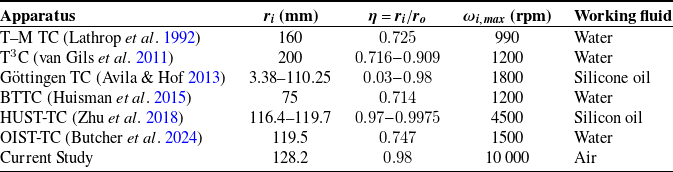
). Table 2 summarises the
$\omega _o=0$
). Table 2 summarises the
 $Ta$
,
$Ta$
,
 $Re$
, applied axial airflow velocity
$Re$
, applied axial airflow velocity
 $U_a$
and
$U_a$
and
 $Re_a$
values for the cases studied at rotation speeds of 2500 and 10 000 rpm.
$Re_a$
values for the cases studied at rotation speeds of 2500 and 10 000 rpm.
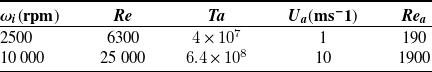
Parameters for the experiments. Here,
 $\omega _i (\mathrm{rpm})$
is the rotation speed of the inner cylinder,
$\omega _i (\mathrm{rpm})$
is the rotation speed of the inner cylinder,
 $Re$
,
$Re$
,
 $Ta$
,
$Ta$
,
 $U_a$
and
$U_a$
and
 $Re_a$
are the Reynolds number based on inner-cylinder rotation, the Taylor number, the axial airflow velocity and the Reynolds number based on the imposed axial flow
$Re_a$
are the Reynolds number based on inner-cylinder rotation, the Taylor number, the axial airflow velocity and the Reynolds number based on the imposed axial flow

4. Results
4.1. Mean velocity profile and flow structure
In figure 4, we first present the normalised mean azimuthal velocity field at a fixed axial position for two Taylor numbers,
 $Ta = 4.0\times 10^7$
and
$Ta = 4.0\times 10^7$
and
 $Ta = 6.4\times 10^8$
. Velocities are normalised by the inner-cylinder wall speed. For the lower
$Ta = 6.4\times 10^8$
. Velocities are normalised by the inner-cylinder wall speed. For the lower
 $Ta$
, velocity vectors decrease gradually from the inner to the outer cylinder. For the higher
$Ta$
, velocity vectors decrease gradually from the inner to the outer cylinder. For the higher
 $Ta$
, stronger velocity gradients emerge near both the inner- and outer-cylinder walls, while the bulk region remains nearly uniform. These results suggest that increasing
$Ta$
, stronger velocity gradients emerge near both the inner- and outer-cylinder walls, while the bulk region remains nearly uniform. These results suggest that increasing
 $Ta$
progressively makes the boundary layers become thinner, resulting in enhanced uniformity within the bulk region. The results for the remaining 17 axial position also support the same conclusion.
$Ta$
progressively makes the boundary layers become thinner, resulting in enhanced uniformity within the bulk region. The results for the remaining 17 axial position also support the same conclusion.
Time-averaged azimuthal velocity fields
 $\overline {u_\theta }$
in the
$\overline {u_\theta }$
in the
 $r-\theta$
plane at a fixed axial position for two Taylor numbers; (a)
$r-\theta$
plane at a fixed axial position for two Taylor numbers; (a)
 $Ta = \textit{4} \times \textit{10}^{\textit{7}}$
(corresponding to 2500 rpm), (b)
$Ta = \textit{4} \times \textit{10}^{\textit{7}}$
(corresponding to 2500 rpm), (b)
 $Ta = \textit{6.4} \times \textit{10}^{\textit{8}}$
(corresponding to 10 000 rpm).
$Ta = \textit{6.4} \times \textit{10}^{\textit{8}}$
(corresponding to 10 000 rpm).

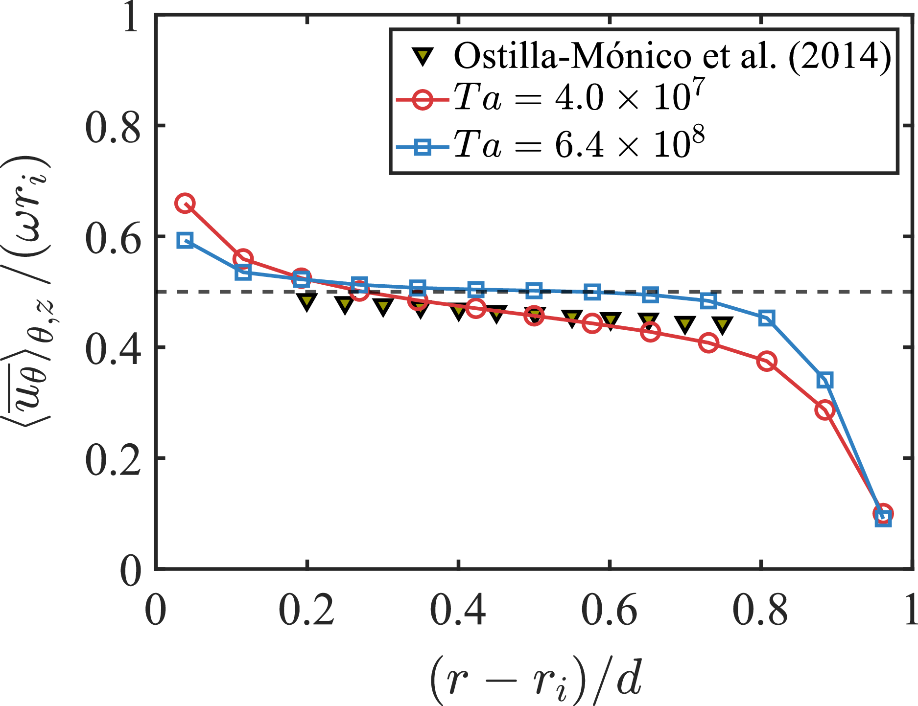
Radial profiles of normalised mean azimuthal velocity
 $ \langle \overline {u_{\theta} } \rangle _{\theta ,z}$
for two Taylor numbers,
$ \langle \overline {u_{\theta} } \rangle _{\theta ,z}$
for two Taylor numbers,
 $Ta = \textit{4.0} \times \textit{10}^{\textit{7}}$
and
$Ta = \textit{4.0} \times \textit{10}^{\textit{7}}$
and
 $Ta = \textit{6.4} \times \textit{10}^{\textit{8}}$
. Data are compared with results from Ostilla-Mónico et al. (Reference Ostilla-Mónico, van der Poel, Verzicco, Grossmann and Lohse2014
b), obtained using LDA at radius ratio
$Ta = \textit{6.4} \times \textit{10}^{\textit{8}}$
. Data are compared with results from Ostilla-Mónico et al. (Reference Ostilla-Mónico, van der Poel, Verzicco, Grossmann and Lohse2014
b), obtained using LDA at radius ratio
 $\eta =0.909$
,
$\eta =0.909$
,
 $Ta=\textit{1.1} \times \textit{10}^{\textit{11}}$
.
$Ta=\textit{1.1} \times \textit{10}^{\textit{11}}$
.

Figure 5 presents the radial distribution of the normalised mean azimuthal velocity
 $\left \langle \overline {u_\theta } \right \rangle _{\theta ,z}$
obtained from time-averaged velocity fields (figure 4). The profiles are shown for two Taylor numbers,
$\left \langle \overline {u_\theta } \right \rangle _{\theta ,z}$
obtained from time-averaged velocity fields (figure 4). The profiles are shown for two Taylor numbers,
 $Ta = 4.0\times 10^7$
and
$Ta = 4.0\times 10^7$
and
 $Ta = 6.4\times 10^8$
, and are compared with the LDA measurements of Ostilla-Mónico et al. (Reference Ostilla-Mónico, van der Poel, Verzicco, Grossmann and Lohse2014
b) performed at a radius ratio
$Ta = 6.4\times 10^8$
, and are compared with the LDA measurements of Ostilla-Mónico et al. (Reference Ostilla-Mónico, van der Poel, Verzicco, Grossmann and Lohse2014
b) performed at a radius ratio
 $\eta = 0.909$
and a higher driving strength
$\eta = 0.909$
and a higher driving strength
 $Ta = 1.1 \times 10^{11}$
. Although the LDA data of Ostilla-Mónico et al. (Reference Ostilla-Mónico, van der Poel, Verzicco, Grossmann and Lohse2014
b) were obtained at
$Ta = 1.1 \times 10^{11}$
. Although the LDA data of Ostilla-Mónico et al. (Reference Ostilla-Mónico, van der Poel, Verzicco, Grossmann and Lohse2014
b) were obtained at
 $Ta$
larger than those considered here, and at a different radius ratio
$Ta$
larger than those considered here, and at a different radius ratio
 $\eta$
, they provide the closest experimental benchmark currently available for our operating conditions. All velocities are normalised by the inner-cylinder wall speed. At both driving strengths, the profiles display the characteristic structure of TC flow with steep gradients near the walls and a relatively flat bulk region. For the lower
$\eta$
, they provide the closest experimental benchmark currently available for our operating conditions. All velocities are normalised by the inner-cylinder wall speed. At both driving strengths, the profiles display the characteristic structure of TC flow with steep gradients near the walls and a relatively flat bulk region. For the lower
 $Ta$
, the mean velocity decreases gradually from the inner cylinder toward the outer wall, revealing a gentle radial variation of angular momentum. At the higher
$Ta$
, the mean velocity decreases gradually from the inner cylinder toward the outer wall, revealing a gentle radial variation of angular momentum. At the higher
 $Ta$
, the profile becomes nearly uniform across the central region and maintains a magnitude close to 0.5, reflecting enhanced turbulent mixing and a more homogeneous distribution of angular momentum. The comparison with Ostilla-Mónico et al. (Reference Ostilla-Mónico, van der Poel, Verzicco, Grossmann and Lohse2014b) shows that the present profiles lie slightly above those at
$Ta$
, the profile becomes nearly uniform across the central region and maintains a magnitude close to 0.5, reflecting enhanced turbulent mixing and a more homogeneous distribution of angular momentum. The comparison with Ostilla-Mónico et al. (Reference Ostilla-Mónico, van der Poel, Verzicco, Grossmann and Lohse2014b) shows that the present profiles lie slightly above those at
 $\eta = 0.909$
, which suggests the possible influence of reduced curvature. The sharper drop near the outer cylinder observed at the higher
$\eta = 0.909$
, which suggests the possible influence of reduced curvature. The sharper drop near the outer cylinder observed at the higher
 $Ta$
implies a very thin velocity boundary layer. For turbulent TC flow, the velocity boundary layer thickness
$Ta$
implies a very thin velocity boundary layer. For turbulent TC flow, the velocity boundary layer thickness
 $\delta$
in the present configuration with
$\delta$
in the present configuration with
 $\omega _o = 0$
can be estimated as
$\omega _o = 0$
can be estimated as
 $\delta \approx d / 2 Nu$
(Brauckmann et al. Reference Brauckmann, Eckhardt and Schumacher2017). Since we do not measure torque directly, we cannot determine
$\delta \approx d / 2 Nu$
(Brauckmann et al. Reference Brauckmann, Eckhardt and Schumacher2017). Since we do not measure torque directly, we cannot determine
 $Nu$
from our experiments. However, Zhu et al. (Reference Zhu, Ji, Lou and Qian2018) measured the torque for geometries with
$Nu$
from our experiments. However, Zhu et al. (Reference Zhu, Ji, Lou and Qian2018) measured the torque for geometries with
 $\eta$
very close to ours. Their experiments covered
$\eta$
very close to ours. Their experiments covered
 $0.97 \leq \eta \leq 0.9975$
, while our value is
$0.97 \leq \eta \leq 0.9975$
, while our value is
 $\eta = 0.98$
. From their data at
$\eta = 0.98$
. From their data at
 $Ta = 6.4 \times 10^8$
, we take
$Ta = 6.4 \times 10^8$
, we take
 $Nu \approx 100$
. This gives
$Nu \approx 100$
. This gives
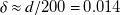 $\delta \approx d/200 = 0.014$
mm, which is well below our spatial resolution (
$\delta \approx d/200 = 0.014$
mm, which is well below our spatial resolution (
 $\approx$
0.2 mm).
$\approx$
0.2 mm).
The velocity profile presented in figure 5 is found to be consistent with the expected transition toward the ultimate turbulent regime (Ostilla-Mónico et al. Reference Ostilla-Mónico, van der Poel, Verzicco, Grossmann and Lohse2014
b; Brauckmann et al. Reference Brauckmann, Eckhardt and Schumacher2017; Froitzheim et al. Reference Froitzheim, Merbold and Egbers2017, Reference Froitzheim, Ezeta, Huisman, Merbold, Sun, Lohse and Egbers2019), in which angular momentum becomes almost radially uniform and the boundary layers progressively lose their laminar character. Since we do not measure torque directly, we cannot determine
 $Nu$
from our experiments, and we therefore cannot unambiguously identify whether our operating conditions lie in the ultimate regime. However, the experiments of Zhu et al. (Reference Zhu, Ji, Lou and Qian2018) indicate that for
$Nu$
from our experiments, and we therefore cannot unambiguously identify whether our operating conditions lie in the ultimate regime. However, the experiments of Zhu et al. (Reference Zhu, Ji, Lou and Qian2018) indicate that for
 $\eta \ge 0.97$
the transition to the ultimate regime occurs at a substantially lower Taylor number, around
$\eta \ge 0.97$
the transition to the ultimate regime occurs at a substantially lower Taylor number, around
 $Ta \approx 3.5 \times 10^7$
, than in the well-studied case
$Ta \approx 3.5 \times 10^7$
, than in the well-studied case
 $\eta = 0.714$
, where the transition is reported near
$\eta = 0.714$
, where the transition is reported near
 $Ta \approx 3 \times 10^8$
. On this basis, our experimental conditions are expected to lie in the ultimate regime.
$Ta \approx 3 \times 10^8$
. On this basis, our experimental conditions are expected to lie in the ultimate regime.
Reconstructed
 $z-r$
plane mean azimuthal velocity fields
$z-r$
plane mean azimuthal velocity fields
 $ \langle \overline {u_\theta } \rangle$
obtained by axially stitching results from 18 measurement positions for two Taylor numbers; (a)
$ \langle \overline {u_\theta } \rangle$
obtained by axially stitching results from 18 measurement positions for two Taylor numbers; (a)
 $Ta = \textit{4} \times \textit{10}^{\textit{7}}$
(corresponding to 2500 rpm), (b)
$Ta = \textit{4} \times \textit{10}^{\textit{7}}$
(corresponding to 2500 rpm), (b)
 $Ta = \textit{6.4} \times \textit{10}^{\textit{8}}$
(corresponding to 10 000 rpm).
$Ta = \textit{6.4} \times \textit{10}^{\textit{8}}$
(corresponding to 10 000 rpm).

Figure 6 presents the reconstructed axial–radial (
 $z$
–
$z$
–
 $r$
) mean velocity fields obtained by assembling the 18 mean (
$r$
) mean velocity fields obtained by assembling the 18 mean (
 $r$
–
$r$
–
 $\theta$
) velocity fields, with no evident large-scale structures, consistent with previous findings (Froitzheim et al. Reference Froitzheim, Ezeta, Huisman, Merbold, Sun, Lohse and Egbers2019; Zhang et al. Reference Zhang, Fan, Su, Xi and Sun2025). An important question is how the imposed axial flow influences the mean velocity field described above. From a dimensional perspective, the maximum imposed axial velocity (
$\theta$
) velocity fields, with no evident large-scale structures, consistent with previous findings (Froitzheim et al. Reference Froitzheim, Ezeta, Huisman, Merbold, Sun, Lohse and Egbers2019; Zhang et al. Reference Zhang, Fan, Su, Xi and Sun2025). An important question is how the imposed axial flow influences the mean velocity field described above. From a dimensional perspective, the maximum imposed axial velocity (
 $U_a = 10\,\mathrm{ms}^{-1}$
) is small compared with the inner-cylinder circumferential velocity at the highest rotation rate (approximately
$U_a = 10\,\mathrm{ms}^{-1}$
) is small compared with the inner-cylinder circumferential velocity at the highest rotation rate (approximately
 $134\,\mathrm{ms}^{-1}$
). We therefore expect the axial flow to cause only a very mild change in the mean velocity profiles, rather than a dramatic modification. For the TC flow with an axial flow, Wereley and Lueptow (Reference Wereley and Lueptow1999) suggested that the ratio
$134\,\mathrm{ms}^{-1}$
). We therefore expect the axial flow to cause only a very mild change in the mean velocity profiles, rather than a dramatic modification. For the TC flow with an axial flow, Wereley and Lueptow (Reference Wereley and Lueptow1999) suggested that the ratio
 $Ta/Re_a$
measures the relative strength of centrifugal effects to axial momentum effects. Their PIV measurements showed that, at large
$Ta/Re_a$
measures the relative strength of centrifugal effects to axial momentum effects. Their PIV measurements showed that, at large
 $Ta/Re_a$
, the flow field is nearly the same as without axial flow, with the main difference being an axial translation of the vortex pattern. Later numerical studies with similar geometries and parameter ranges reported consistent behaviour (Hwang & Yang Reference Hwang and Yang2004; Manna & Vacca Reference Manna and Vacca2009). For
$Ta/Re_a$
, the flow field is nearly the same as without axial flow, with the main difference being an axial translation of the vortex pattern. Later numerical studies with similar geometries and parameter ranges reported consistent behaviour (Hwang & Yang Reference Hwang and Yang2004; Manna & Vacca Reference Manna and Vacca2009). For
 $U_a = 10$
ms−1, we obtain
$U_a = 10$
ms−1, we obtain
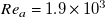 $Re_a = 1.9\times 10^3$
, which gives
$Re_a = 1.9\times 10^3$
, which gives
 $Ta/Re_a = 3.4\times 10^5$
. This value is at least three orders of magnitude larger than the transitional values reported in the literature. It therefore supports the expectation that only minor changes in the azimuthal mean profile should occur. We note, however, that the available studies of TC flow with imposed axial flow were conducted at
$Ta/Re_a = 3.4\times 10^5$
. This value is at least three orders of magnitude larger than the transitional values reported in the literature. It therefore supports the expectation that only minor changes in the azimuthal mean profile should occur. We note, however, that the available studies of TC flow with imposed axial flow were conducted at
 $(Ta, Re_a)$
values that are much smaller than those in our experiments. Further validation at our high Taylor numbers would therefore be valuable. Overall, despite the intensified shear in boundary layer, large-scale coherent structures remain absent, suggesting that, at our operating conditions (high
$(Ta, Re_a)$
values that are much smaller than those in our experiments. Further validation at our high Taylor numbers would therefore be valuable. Overall, despite the intensified shear in boundary layer, large-scale coherent structures remain absent, suggesting that, at our operating conditions (high
 $Ta$
, narrow gap and with axial flow), large-scale coherent structures are either suppressed or have broken down into smaller-scale turbulence.
$Ta$
, narrow gap and with axial flow), large-scale coherent structures are either suppressed or have broken down into smaller-scale turbulence.
(a) The PDF of the normalised azimuthal velocity gradient along the radial direction
 $ {\partial u_\theta }/{\partial r}$
, (b) PDF of the normalised azimuthal velocity gradient along the azimuthal direction
$ {\partial u_\theta }/{\partial r}$
, (b) PDF of the normalised azimuthal velocity gradient along the azimuthal direction
 ${\partial u_\theta }/{\partial x_\theta }$
. Black dashed curve in (b) shows best Gaussian fit at
${\partial u_\theta }/{\partial x_\theta }$
. Black dashed curve in (b) shows best Gaussian fit at
 $Ta = \textit{6.4} \times \textit{10}^{\textit{8}}$
.
$Ta = \textit{6.4} \times \textit{10}^{\textit{8}}$
.

Radial profiles of Reynolds shear stress
 $\langle {u^\prime _\theta u^\prime _r} \rangle _{\theta ,z}$
, normalised by the square of the inner wall velocity.
$\langle {u^\prime _\theta u^\prime _r} \rangle _{\theta ,z}$
, normalised by the square of the inner wall velocity.

The probability density functions (PDFs) of the azimuthal velocity gradients provide further insight into the spatial intermittency of the flow. Figure 7(a) presents the PDF of the normalised azimuthal velocity gradient along the radial direction
 $ {\partial u_\theta }/{\partial r}$
. At the higher Taylor number,
$ {\partial u_\theta }/{\partial r}$
. At the higher Taylor number,
 $Ta = 6.4 \times 10^8$
, the PDF has larger probabilities at high gradient magnitudes. This trend is consistent with boundary layer thinning and the resulting steeper near-wall velocity gradients, as indicated by the mean profiles in figure 5. It also reflects the increase in local shear with increasing driving strength. The PDF at
$Ta = 6.4 \times 10^8$
, the PDF has larger probabilities at high gradient magnitudes. This trend is consistent with boundary layer thinning and the resulting steeper near-wall velocity gradients, as indicated by the mean profiles in figure 5. It also reflects the increase in local shear with increasing driving strength. The PDF at
 $Ta = 6.4 \times 10^8$
also shows higher probability at small gradient magnitudes. This behaviour is consistent with a flatter bulk profile and a more uniform azimuthal velocity distribution across the central part of the gap, as seen in figure 5. Figure 7(b) shows the PDF of the normalised azimuthal gradient of the azimuthal velocity,
$Ta = 6.4 \times 10^8$
also shows higher probability at small gradient magnitudes. This behaviour is consistent with a flatter bulk profile and a more uniform azimuthal velocity distribution across the central part of the gap, as seen in figure 5. Figure 7(b) shows the PDF of the normalised azimuthal gradient of the azimuthal velocity,
 ${\partial u_\theta }/{\partial x_\theta }$
. As
${\partial u_\theta }/{\partial x_\theta }$
. As
 $Ta$
increases, the PDF near zero becomes closer to a Gaussian shape, although the range over which this Gaussian behaviour holds remains limited, as indicated by the dashed curve in Figure 7(b). This change is consistent with increasing turbulence intensity at higher
$Ta$
increases, the PDF near zero becomes closer to a Gaussian shape, although the range over which this Gaussian behaviour holds remains limited, as indicated by the dashed curve in Figure 7(b). This change is consistent with increasing turbulence intensity at higher
 $Ta$
. Stronger mixing tends to homogenise small and moderate velocity gradients and to reduce directional differences at these amplitudes. As a result, the central part of the gradient PDF moves closer to Gaussian. Despite this trend in the core, both cases exhibit clear non-Gaussian behaviour in the tails. The tails deviate strongly from the best fit Gaussian, indicating rare but intense gradient events. These heavy tails signify the presence of extreme gradient events and strong small-scale intermittency in the azimuthal direction. The broadening of PDF with increasing higher
$Ta$
. Stronger mixing tends to homogenise small and moderate velocity gradients and to reduce directional differences at these amplitudes. As a result, the central part of the gradient PDF moves closer to Gaussian. Despite this trend in the core, both cases exhibit clear non-Gaussian behaviour in the tails. The tails deviate strongly from the best fit Gaussian, indicating rare but intense gradient events. These heavy tails signify the presence of extreme gradient events and strong small-scale intermittency in the azimuthal direction. The broadening of PDF with increasing higher
 $Ta$
suggests a transition toward more intense and spatially localised velocity fluctuations, characteristic of the enhanced turbulence levels associated with the approach to the ultimate regime.
$Ta$
suggests a transition toward more intense and spatially localised velocity fluctuations, characteristic of the enhanced turbulence levels associated with the approach to the ultimate regime.
4.2. Reynolds shear stress
Figure 8 shows the radial distribution of the Reynolds shear stress
 $\left \langle u'_\theta u'_r \right \rangle _{\theta ,z}$
, normalised by the square of the inner-cylinder surface speed. In both cases, the Reynolds stress exhibits a pronounced plateau in the bulk region, indicating that turbulent momentum transport is predominantly concentrated in this central part of the gap. At
$\left \langle u'_\theta u'_r \right \rangle _{\theta ,z}$
, normalised by the square of the inner-cylinder surface speed. In both cases, the Reynolds stress exhibits a pronounced plateau in the bulk region, indicating that turbulent momentum transport is predominantly concentrated in this central part of the gap. At
 $Ta = 4 \times 10^7$
, the Reynolds stress is notably asymmetric, with higher values near the inner cylinder compared with the outer cylinder. This asymmetry is likely associated with the residual influence of Görtler-type vortical structures that persist at moderate rotation rates (Dong Reference Dong2007). Such asymmetry is expected to diminish as the flow approaches the rotating plane Couette limit (Deguchi Reference Deguchi2016). At higher
$Ta = 4 \times 10^7$
, the Reynolds stress is notably asymmetric, with higher values near the inner cylinder compared with the outer cylinder. This asymmetry is likely associated with the residual influence of Görtler-type vortical structures that persist at moderate rotation rates (Dong Reference Dong2007). Such asymmetry is expected to diminish as the flow approaches the rotating plane Couette limit (Deguchi Reference Deguchi2016). At higher
 $Ta$
, the Reynolds stress distribution becomes more symmetric about the mid-gap, reflecting the breakdown of coherent structures and the emergence of more homogeneous turbulence in the bulk. The resulting symmetry is aligned with the narrow-gap limit perspective (Deguchi Reference Deguchi2016), in which the flow more closely resembles rotating plane Couette flow and does not exhibit the same curvature-driven asymmetry. Interestingly, the magnitude of the normalised Reynolds stress decreases with increasing
$Ta$
, the Reynolds stress distribution becomes more symmetric about the mid-gap, reflecting the breakdown of coherent structures and the emergence of more homogeneous turbulence in the bulk. The resulting symmetry is aligned with the narrow-gap limit perspective (Deguchi Reference Deguchi2016), in which the flow more closely resembles rotating plane Couette flow and does not exhibit the same curvature-driven asymmetry. Interestingly, the magnitude of the normalised Reynolds stress decreases with increasing
 $Ta$
, consistent with previous observations (Naim & Baig Reference Naim and Baig2019), suggesting a redistribution of angular-momentum transport mechanisms and a possible reduction in the relative contribution of Reynolds stresses in the ultimate regime. One may wonder how the imposed axial flow influences the Reynolds stress profile here. Manna and Vacca (Reference Manna and Vacca2009) performed Direct Numerical Simulation (DNS) of
$Ta$
, consistent with previous observations (Naim & Baig Reference Naim and Baig2019), suggesting a redistribution of angular-momentum transport mechanisms and a possible reduction in the relative contribution of Reynolds stresses in the ultimate regime. One may wonder how the imposed axial flow influences the Reynolds stress profile here. Manna and Vacca (Reference Manna and Vacca2009) performed Direct Numerical Simulation (DNS) of
 $\eta =0.98$
TC flow with an imposed axial pressure gradient. They found that, as the axial Reynolds number
$\eta =0.98$
TC flow with an imposed axial pressure gradient. They found that, as the axial Reynolds number
 $Re_a$
increases, the turbulent contribution to the shear stress in the bulk decreases, while the viscous contribution increases. As we have
$Re_a$
increases, the turbulent contribution to the shear stress in the bulk decreases, while the viscous contribution increases. As we have
 $Ta/Re_a = 3.4\times 10^5$
, which is much larger than the values considered by Manna and Vacca (Reference Manna and Vacca2009), this indicates that our flow is strongly rotation dominated. We therefore expect the changes in Reynolds stress profile in our experiments to be smaller than those reported by Manna and Vacca (Reference Manna and Vacca2009). At the present stage, we cannot confirm this expectation with our current measurements. A dedicated parametric study, in which the axial flow is varied independently, will be needed to quantify the effect on the Reynolds stress profile.
$Ta/Re_a = 3.4\times 10^5$
, which is much larger than the values considered by Manna and Vacca (Reference Manna and Vacca2009), this indicates that our flow is strongly rotation dominated. We therefore expect the changes in Reynolds stress profile in our experiments to be smaller than those reported by Manna and Vacca (Reference Manna and Vacca2009). At the present stage, we cannot confirm this expectation with our current measurements. A dedicated parametric study, in which the axial flow is varied independently, will be needed to quantify the effect on the Reynolds stress profile.
5. Summary
This study introduced the NPU-TC apparatus, which enables comprehensive exploration of TC flow under extreme operational conditions representative of high-speed rotating electrical machinery. The facility features a stationary outer cylinder and an ultra-high-speed rotating inner cylinder, achieving rotation rates up to 10 000 rpm (Taylor number
 $Ta=6.4\times 10^8$
) with a minimal annular gap of only 2.8 mm and a radius ratio of 0.98. These conditions accurately emulate realistic operating environments encountered in modern high-speed electrical machines. Rigorous control mechanisms ensure exceptional stability in rotation speed (variation less than 0.5
$Ta=6.4\times 10^8$
) with a minimal annular gap of only 2.8 mm and a radius ratio of 0.98. These conditions accurately emulate realistic operating environments encountered in modern high-speed electrical machines. Rigorous control mechanisms ensure exceptional stability in rotation speed (variation less than 0.5
 $\,\%$
) and vibration levels adhering to ISO 10,816 top-class standards, critical for ensuring the reliability and repeatability of high-speed flow measurements.
$\,\%$
) and vibration levels adhering to ISO 10,816 top-class standards, critical for ensuring the reliability and repeatability of high-speed flow measurements.
Employing axial-scanning PIV, we obtained detailed, non-intrusive measurements of the velocity fields within the TC gap, overcoming the limitations associated with traditional measurement methods such as hot-wire anemometry in extremely narrow geometries. The axial–radial velocity fields revealed a significant reduction in boundary layer thickness and the notable absence of large-scale coherent vortical structures, consistent with the theoretical prediction for flows approaching the ultimate turbulence regime. Our analysis of mean azimuthal velocity profiles shows clear evidence of stronger mixing in the bulk and thinner boundary layer with increased rotation rates. At the highest Taylor number (
 $Ta = 6.4 \times 10^8$
), the bulk region exhibited a nearly uniform angular-momentum distribution, consistent with trends reported for flows approaching the ultimate regime. However, it should be noted that this feature can appear even when the flow is not in the ultimate regime (see Deguchi Reference Deguchi2023). Furthermore, PDFs of azimuthal velocity gradients highlight pronounced spatial intermittency and small-scale turbulence intensification near cylinder boundaries, confirming enhanced turbulent activity. Radial profiles of the Reynolds shear stress demonstrated a transition from asymmetric distributions at moderate Taylor numbers to more symmetric profiles at higher rotation speeds, suggesting the breakdown of residual coherent structures and the emergence of fully developed, homogeneous turbulence in the central region. This transition signifies a fundamental shift in momentum transport mechanisms under extreme turbulent conditions.
$Ta = 6.4 \times 10^8$
), the bulk region exhibited a nearly uniform angular-momentum distribution, consistent with trends reported for flows approaching the ultimate regime. However, it should be noted that this feature can appear even when the flow is not in the ultimate regime (see Deguchi Reference Deguchi2023). Furthermore, PDFs of azimuthal velocity gradients highlight pronounced spatial intermittency and small-scale turbulence intensification near cylinder boundaries, confirming enhanced turbulent activity. Radial profiles of the Reynolds shear stress demonstrated a transition from asymmetric distributions at moderate Taylor numbers to more symmetric profiles at higher rotation speeds, suggesting the breakdown of residual coherent structures and the emergence of fully developed, homogeneous turbulence in the central region. This transition signifies a fundamental shift in momentum transport mechanisms under extreme turbulent conditions.
Another important issue is the potential role of compressibility under the present extreme conditions. At the maximum rotation rate of 10 000 rpm, the inner-cylinder surface speed is approximately 134 ms−1. Using a speed of sound in air at 20
 $\,^\circ$
C of approximately 343 ms−1, the corresponding Mach number is
$\,^\circ$
C of approximately 343 ms−1, the corresponding Mach number is
 $Ma \approx 0.39$
. Although the flow remains subsonic, this Mach number is sufficiently high that compressibility effects may influence the TC dynamics and should be considered (Aghor & Alam Reference Aghor and Alam2021; Kuhlthau Reference Kuhlthau1949). Shear heating is also a concern at these rotation rates. In the present experiments, the surface temperature is monitored using three infrared temperature sensors. The measured temperature remains stable within
$Ma \approx 0.39$
. Although the flow remains subsonic, this Mach number is sufficiently high that compressibility effects may influence the TC dynamics and should be considered (Aghor & Alam Reference Aghor and Alam2021; Kuhlthau Reference Kuhlthau1949). Shear heating is also a concern at these rotation rates. In the present experiments, the surface temperature is monitored using three infrared temperature sensors. The measured temperature remains stable within
 $\pm 0.5\,^\circ$
C. This stability is achieved through a combination of active cooling and the imposed axial airflow. The active cooling is provided by a refrigerated circulator that maintains the stator at 20
$\pm 0.5\,^\circ$
C. This stability is achieved through a combination of active cooling and the imposed axial airflow. The active cooling is provided by a refrigerated circulator that maintains the stator at 20
 $\,^\circ$
C. The small temperature variation suggests that shear heating is effectively controlled under the conditions reported here. Even so, shear heating may still play a role in the local thermal balance, especially near the walls. Future measurements that resolve temperature gradients in the gap would be valuable for quantifying any remaining thermal effects and for assessing their influence on the flow.
$\,^\circ$
C. The small temperature variation suggests that shear heating is effectively controlled under the conditions reported here. Even so, shear heating may still play a role in the local thermal balance, especially near the walls. Future measurements that resolve temperature gradients in the gap would be valuable for quantifying any remaining thermal effects and for assessing their influence on the flow.
Looking forward, the NPU-TC apparatus provides a versatile experimental platform to investigate the effects of varying stator topologies on turbulent TC flow. Future experiments are planned to systematically alter stator geometrical configurations, including surface textures, groove patterns and innovative structural modifications. Such investigations will directly address open questions regarding the optimisation of stator designs in rotating electrical machinery, specifically targeting improvements in aerodynamic performance, heat transfer efficiency and overall system reliability. Insights gained from these studies will significantly inform design strategies, enabling the engineering of advanced high-speed rotating electrical machines with enhanced operational stability and energy efficiency.
Acknowledgements
We sincerely thank Mr H.-Y. Zhou and his company for their contributions to the design and construction of the apparatus, and Mrs J.-Y. Zhang (Shanghai Marine Equipment Research Institute) for her valuable guidance and support in this regard.
Data availability statement
Raw data are available from the corresponding authors.
Author contributions
X.-R. Liu and X.-J. Wang contributed equally to this work.
Funding statement
This work was supported by the Shanghai Marine Equipment Research Institute (SMERI) and National Natural Science Foundation of China (NSFC) under grant nos. 12125204, 12388101 and 12502258, the 111 project of China (no. B17037) and the Innovation Capability Support Program of Shaanxi (Program No. 2024RS-CXTD-15).
Declaration of interests
The authors declare no conflicts of interest.
Ethical standards
The research meets all ethical guidelines, including adherence to the legal requirements of the study country.


 Open access