


1. Introduction
The aerospace industry faces supply chain disruptions, caused by geopolitical conflicts, economic instability, and unpredictable events. These factors have resulted in shortages of high-performance superalloys used in aero engine manufacturing. Consequently, many aircrafts are being operated beyond their intended service life, further increasing the demand for reliable and cost-effective Maintenance, Repair and Overhaul (MRO) services (Reference DuboisDubois, 2024). Within this context, the repair of turbine blades has emerged as a focal point of both sustainability and economic interest. Turbine blades are not only among the most wear-prone parts, accounting for approximately 50% of engine-related failures (Reference García-Martínez, del Hoyo Gordillo, Valles González, Pastor Muro and González CaballeroGarcía-Martínez et al., 2023), but also among the most costly to replace. A new set of 40 blades can require 60 to 90 weeks to manufacture and cost up to USD 600,000, or USD 15,000 per blade (Reference Angel and BasakAngel & Basak, 2020). Extending their service life through repair thus offers substantial cost savings and contributes to more sustainable resource utilization. However, the industrial repair of turbine blades presents considerable challenges, particularly due to the continued reliance on manual, hand-guided processes. These human-dependent methods introduce variability in quality, limit production efficiency, and restrict scalability. Factors that are increasingly problematic in context of the growing repair backlog. With global MRO shop capacities already fully booked for years in advance and long waiting times for engine repairs becoming the norm (Reference Denkena, Westermann and FriebeDenkena et al., 2025), addressing the limitations of current repair methodologies is imperative for the MRO industry’s resilience and sustainability. Additive repair has emerged as a suitable strategy for extending the service life of high-value metallic parts, particularly in domains where material scarcity, long lead times, and high production costs necessitate alternative maintenance approaches. Additive manufacturing processes such as Directed Energy Deposition (DED) and Powder Bed Fusion using a Laser Beam for Metals (PBF-LB/M) have been identified as suitable methods for the repair of metallic parts (Reference Leino, Pekkarinen and SoukkaLeino et al., 2016; Reference Rahito and AzmanRahito et al., 2019; Reference Yeo, Pepin and YangYeo et al., 2017; Reference Zghair, Leuteritz, Lachmayer and LippertZghair & Leuteritz, 2017). These techniques enable localized material deposition on damaged areas, although their applicability differs due to process-specific constraints. Existing work shows that DED remains the most established repair technology (Reference Kanishka and AcherjeeKanishka & Acherjee, 2023); however, studies consistently report limitations related to surface finish (Reference Sato, Matsumoto, Ogiso and SatoSato et al., 2022), dimensional fidelity (Reference Godec, Malej, Feizpour, Donik, Balažic, Klobčar, Pambaguian, Conradi and KocijanGodec et al., 2021), and metallurgical bonding quality (Reference Saboori, Aversa, Marchese, Biamino, Lombardi and FinoSaboori et al., 2019). These constraints have motivated increasing interest in PBF-LB/M, which offers superior process resolution and is therefore better suited for parts with intricate geometries and tight tolerances (Reference Sato, Matsumoto, Ogiso and SatoSato et al., 2022). The repair workflow of PBF-LB/M-process follows three key stages: pre-process, in-process, and post-process. Among these, the pre-process stage is typically the most time-intensive, as it involves several manual and computational operations. During this phase, the damaged region is first identified and localized. Subsequently, a planar cutting surface is defined at the defect site to minimize material removal, promote resource efficiency, and ensure compatibility with the PBF-LB/M-process. The requirement for a planar interface arises from the inherent characteristics of PBF-LB/M, which rely on a uniform reference plane to enable consistent powder deposition and accurate layer consolidation throughout the build process. To transform this predominantly full manual sequence into an automatable, and reproducible digital workflow, the present work introduces two purpose-built digital design tools: the Cutting Plane Definition Tool, which systematizes and automates the segmentation of damaged regions, and the Reconstruction Tool, which enables consistent and precise geometric restoration based on the original part design. Complementing these digital methods, a repair fixture for automated alignment was developed to adapt standard PBF-LB/M equipment for turbine-blade repair. A representative repair case demonstrates that the proposed, tool-supported workflow significantly reduces preparation effort while maintaining the geometric fidelity required for high-quality turbine-blade restoration.
This work addresses the question of how the pre-processing stage of PBF-LB/M-based additive repair can be formalized and automated using digital decision-support tools and geometry-adaptive fixturing. In particular, it investigates how manual effort can be reduced without compromising the geometric accuracy required for turbine blade restoration.
2. Related work
2.1. Digital pre-processing strategies for additive repair
Reference Andersson, Graichen, Brodin and NavrotskyAndersson et al. (2016) demonstrated the feasibility of PBF-LB/M for restoring gas turbine burners, reporting high geometric accuracy and robust material integration, thereby positioning PBF-LB/M as a promising alternative for the repair of turbomachinery components. Additive repair using the PBF-LB/M process follows a defined workflow that integrates both digital and physical operations, as illustrated in Figure 1.
Workflow for additive repair using PBF-LB/M

Figure 1 Long description
The flowchart illustrates the workflow for additive repair using PBF-LB/M. The process begins with identifying a damaged part, followed by damage analysis with deep learning. If PBF-LB repair is selected, the system preparation involves sealing and thermal management concepts. The definition of the cutting plane profile and its position follows. The process then moves to part preparation and fixture construction, data creation and preparation, and a check if the prepared part is OK or not. If not OK, rework of the prepared part or modification of the CAD model for AR is performed. The process then proceeds through pre-process, in-process, and post-process stages, concluding with quality control.
The process encompasses the complete sequence from damage identification to material deposition and post-processing of the restored part. Within this workflow, the critical stages for successful repair highlighted in blue in Figure 1 are the pre-processing steps, which establish the necessary conditions for accurate data acquisition, geometric reconstruction, and build preparation (Reference Ganter, Hoppe, Dünte, Gembarski and LachmayerGanter et al., 2022). The pre-processing stage follows a structured workflow comprising the digitisation of the damaged component, geometric deviation analysis against nominal data, segmentation of the defect region, and physical preparation of the surface for material deposition (Reference Rahito and AzmanRahito et al., 2019). When no reference geometry exists, reverse-engineering becomes necessary (Reference Wilson, Piya, Shin, Zhao and RamaniWilson et al., 2014). Furthermore, material compatibility between substrate and repair material is essential to avoid interface defects and thermal mismatch (Reference Zghair, Leuteritz, Lachmayer and LippertZghair & Leuteritz, 2017). Despite its centrality, pre-processing remains dominated by manual, experience-dependent operations such as defect marking, component alignment, and fixture-based positioning (Reference Jhavar, Paul and JainJhavar et al., 2013). These tasks introduce substantial variability and constitute a bottleneck for reproducible and scalable repair.
2.2. Digital assistance tools and geometry processing
Recent research has increasingly focused on digital assistance tools to reduce manual intervention. A notable contribution in this domain is the repair-assistance environment proposed by Reference Ganter, Hoppe, Dünte, Gembarski and LachmayerGanter et al. (2022), who introduced a semi-automated toolchain for part digitisation, defect marking, and repair-volume definition. Their work demonstrates how digital visualisation and automated surface segmentation can significantly shorten preparation times in additive repair workflows. Ganter’s approach underscores the growing relevance of computational pre-processing and provides strong evidence that future repair strategies will rely heavily on digital geometry handling. However, despite these advances, existing solutions still exhibit several limitations. Most current frameworks remain semi-automated, requiring substantial user interaction and expert supervision, particularly during data alignment, threshold adjustment, and repair-volume validation. Another significant limitation lies in the absence of integrated cost and effort estimation, which is crucial for assessing the economic feasibility and operational efficiency of alternative repair strategies. Complementary efforts include automated point-cloud processing frameworks (Reference Li, Gan, Yuan, Bi, Luo, Chen and ZhuLi et al., 2024), machine-learning-based defect detection for repair preparation (Reference ÖzelÖzel, 2025), and voxel-based reconstruction methods that aim to establish consistent repair volumes from partial scans (Reference Otto, Soellner, Kiener, Boschert, Wüchner and SørbyOtto et al., 2024). These approaches share a common goal: to replace subjective, manual decisions with algorithmic and reproducible operations. Nonetheless, their applicability is constrained by data quality dependence, limited generalisation, and high computational demand, with only minimal integration into holistic repair workflows.
2.3. Fixture concepts and automated alignment
A further key aspect of current research concerns the accurate positioning and spatial referencing of the preform inside the PBF-LB/M build chamber. The necessity of achieving precise and adaptable alignment has been highlighted by Reference Merz, Poka, Nilsson, Mohr and HilgenbergMerz et al. (2023), who identified fixture-induced misalignment as a major source of geometric deviation in turbine-part repairs. Recent developments include adjustable clamping systems for curved blades (Reference Poyraz and YandıPoyraz & Yandı, 2021), optical referencing solutions integrated into PBF-LB/M machines (Reference Merz, Poka, Nilsson, Mohr and HilgenbergMerz et al., 2023) and hybrid fixture scanner assemblies enabling closed-loop referencing (Reference Touzé, Navarro Valero, Rückert and HascoëtTouzé et al., 2025). This underlines the necessity of precise fixation for accurate alignment and shows that fixture design must be adapted to the specific machine and component, leading to inherent machine and part dependency.
3. Decision tools for the optimization of part preparation in the PBF-LB/M repair process
3.1. Cut-plane automation
The Cutting Plane Definition Tool developed in this work automates essential pre-processing steps for additive repair using PBF-LB/M. Its primary purpose is to support users in defining an optimal cutting plane for separating damaged and undamaged regions of a turbine blade. Beyond reducing manual effort, the approach addresses the limited reproducibility and transparency of this decision step, which directly influences the feasibility and robustness of the subsequent PBF-LB/M repair process. The tool operates directly within Autodesk Fusion, a CAD platform supporting custom automation through add-ins, and guides the user through a structured workflow. Based on a preceding damage analysis, in which defect types and defect locations are automatically identified, the resulting defect information serves as the input for the tool. This ensures that cutting-plane generation is directly driven by defect-specific constraints rather than purely geometric heuristics. Following part alignment, the model is automatically divided into repairable and non-repairable regions. The tool then detects the defect area and generates the corresponding repair volume fully automatically. Using user-defined parameters such as angular limits, search resolution, machining constraints, and machine-specific process parameters, the tool generates a set of feasible cutting planes. These parameters define the admissible design space and reflect key geometric and process-related constraints relevant for additive repair. The generated planes are evaluated in an iterative loop in which invalid planes, e.g., those cutting into the non-repairable region, are filtered out. This systematic filtering step transforms an otherwise experience-based selection task into a rule-based decision process. For each valid plane, the tool computes geometric data such as the resulting repair volume and build height and combines this information with process-related parameters to support an informed selection of the most suitable cutting plane. These metrics are directly linked to process stability, thermal exposure, and post-processing effort in PBF-LB/M repair. Finally, the tool exports the processed geometry as STL and STEP files as well as a documentation file containing all relevant parameters, enabling traceability and reproducibility of the cutting-plane decision. Figure 2 visualizes the workflow of the Cutting Plane Definition Tool, including alignment verification, defect-cube placement, and automated cutting-plane generation.
Sequential design steps of the cutting plane definition tool (a) turbine blade model in Fusion, (b) alignment verification, (c) defect-cube positioning, (d) repair volume generation

3.2. Digital reconstruction of damaged geometries and build preparation
3.2.1. Reconstruction tool
The Reconstruction Tool serves to digitally reconstruct the damaged geometry based on the repair volume defined by the Cutting Plane Definition Tool. The generated cut volume defines the solid repair body used for additive restoration and thus represents the target geometry for the subsequent PBF-LB/M process. When no nominal CAD model of the component is available, the tool additionally supports reverse-engineering workflows to derive the reference geometry required for defining the target as-designed condition. The Reconstruction Tool was developed as a Python-based add-in integrated into Autodesk Fusion and streamlines the import of nominal and actual geometries, their alignment, the generation of a repair volume, and the export of data for additive manufacturing preparation. By consolidating these steps within a single CAD environment, the approach reduces interface-related inconsistencies and improves the robustness of the digital reconstruction workflow. The alignment process is based on an Iterative Closest Point (ICP) algorithm implemented using the Open3D library. ICP is a surface registration technique that iteratively minimizes the distance between corresponding points of two three-dimensional geometries to determine the optimal spatial transformation. While this approach provides high alignment accuracy in principle, its direct application proved impractical for the repair workflow due to numerical instabilities during Boolean operations and the need for external data handling. To address these limitations, a limited degree of user interaction was incorporated. The user selects corresponding reference points directly within Autodesk Fusion, after which the tool computes and applies the transformation matrix automatically. This hybrid alignment strategy combines minimal manual input with automated computation, prioritizing robustness and stability of downstream operations while maintaining sufficient alignment accuracy for reliable repair-volume generation. The workflow of the Reconstruction Tool, illustrated in Figure 3, begins with the import of nominal and actual geometries, followed by the conversion of mesh data into solid bodies. The alignment is then performed based on the defined reference points, after which the repair volume is created through Boolean subtraction and optionally refined using an offset operation. Finally, the reconstructed geometry is exported in STL and STEP formats for subsequent processing in data preparation or additive manufacturing software.
Sequential design steps for repair-volume extraction and modelling (a) import, (b) alignment, (c) repair volume, (d) reconstruction

3.2.2. Build preparation
After the repair volume has been generated, the next step is the digital preparation of the build model for the additive repair process. This stage transforms the reconstructed geometry into a machine-ready build job and represents the final interface between the digital repair definition and physical fabrication.
The component is first positioned and oriented on the virtual build platform to ensure correct alignment relative to the build plane. This orientation step is critical, as it directly affects geometric accuracy, support structure requirements, and thermal boundary conditions during layer-by-layer fabrication. Support structures are subsequently generated to stabilize the part throughout the process, particularly in regions with overhangs or complex geometric features. Following orientation and support generation, the model is sliced into layers according to the process parameters of the target PBF-LB/M system, including layer thickness, laser power, and scanning strategy. The resulting layer-wise toolpaths are visualized to verify full coverage, identify potential collisions, and evaluate build metrics such as material usage and estimated process time. Once verification is complete, the prepared model is exported as a machine-specific job file ready for execution, as shown in Figure 4. This digital preparation stage ensures that the reconstructed repair geometry is consistently and reproducibly translated into a build sequence, thereby bridging the gap between the virtual repair model and the physical additive manufacturing process.
Machine-ready build preparation of the repair geometry

Figure 4 Long description
Panel A: The left side of the image shows a computer-aided design software interface. The main window displays a 3D model of a turbine blade repair setup. The setup includes a circular base with four vertical red pillars and a central turbine blade. The blade is highlighted with a green section indicating the area of focus for repair. Various tools and options are visible in the software interface, including a toolbar at the top, a properties panel on the right, and a navigation panel on the left. Panel B: The right side of the image provides a magnified view of the green section of the turbine blade. This detailed view shows the intricate geometry of the blade section, highlighting the area that requires repair.
4. Additive repair machine setting
The experimental setup is based on an Aconity3D MIDI+ system (shown in Figure 5), a PBF-LB/M machine equipped with a build plate diameter of 250 mm and a maximum build height of 250 mm. For additive repair applications, however, the native machine architecture does not inherently support the stable positioning of complex, non-planar parts such as turbine blades. The system is also configured to support the repair of scalable parts with overall heights of up to 2500 mm through sequential repositioning and fixturing strategies. To enable reliable processing under these conditions, a dedicated fixation system was developed. This fixture ensures secure part retention, accurate alignment, and high positional repeatability, thereby preventing vibration or displacement during powder recoating and laser exposure.
Interior view of the Aconity 3D MIDI+ build chamber; (A) coater, (B) and (D) powder reservoir, (C) build platform, (E) powder overflow, (F) optical lens

4.1. Fixation system
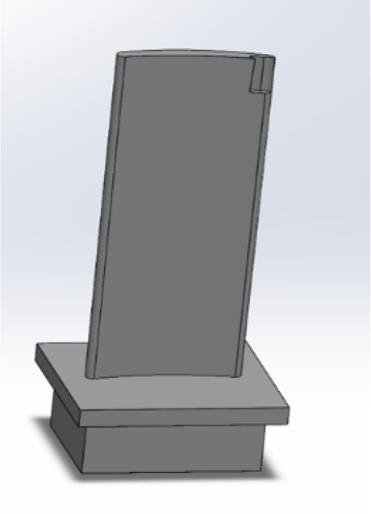
The design of the fixture system is strongly dependent on the machine used, as its build volume, platform layout, and boundary constraints define the available installation space and mounting options. At the same time, the fixture must accommodate the specific geometry of each turbine blade, requiring tailored dimensions and clamping configurations for different parts. Knowing that the second-stage turbine blade of a high-pressure turbine section share the same root form as the parts targeted for repair, the fixation concept could be focused on this common geometric interface rather than on full blade variability. The blade geometry was simplified for validation purposes, retaining the characteristic airfoil curvature while reducing secondary complexity. This allows the evaluation of digital preparation steps and mechanical integration under controlled but representative conditions. Figure 7 shows the simplified blade model used throughout the development and testing of the fixation system. For such blades with conventional root geometries, the central support block with a friction-fit interface remains suitable for achieving precise and repeatable positioning.
Geometry-reduced blade model for controlled validation of the repair setup

The developed fixation system, shown in Figure 6, provides a robust mechanical basis for accurate and repeatable blade positioning. In this work, only this part of the system was adapted. The friction-fit mechanism was redesigned to enable semi-automated positioning and clamping of the blade root, thereby increasing handling efficiency and improving repeatability while keeping the remainder of the fixture design unchanged. To ensure broader applicability, the fixture should remain semi-automated, as a complete redesign for every new blade type would be inefficient.
Fixation system adapted for turbine blade root clamping (a) base unit with friction-fit blade holder, (b) intermediate plate for cavity reduction, (c) closed lid with sealed top plate

4.2. Preform detection
In additive repair processes such as PBF-LB/M, one of the main challenges is achieving precise alignment between the digital repair model and the physical component mounted on the build platform. Even small misalignments can result in incomplete fusion, geometric deviations, or failure of the repair process, especially for complex, high-value components such as turbine blades. In advanced systems like the Aconity MIDI+, this challenge is addressed through automated preform detection. A high-resolution camera captures images (shown in Figure 8) of the mounted part under controlled illumination, and the software identifies reference features, such as edges, corners, or contours. The digital repair geometry is then aligned with the actual part by applying precise translations and rotations until a consistent overlay is achieved. The preform detection method establishes a fully registered correspondence between the digital and physical preform. This ensures an accurate spatial reference for the subsequent laser exposure process. The resulting alignment data are directly integrated into the laser exposure job, ensuring that the additive repair process is accurately referenced to the physical part. This automated approach offers several key advantages: it enables high-precision alignment, reduces operator-dependent variability, improves repeatability, and maintains a consistent reference framework throughout the repair process. As a result, the deposited layers exhibit enhanced geometric fidelity and surface integrity, reducing the need for post-processing and rework.
Camera acquisitions utilized for automated preform detection and pose alignment

5. Discussion
The following discussion addresses the validation of the developed tools and the associated fixation system through the repair of a representative turbine blade tip. To assess their contribution within a realistic application context, the Cutting Plane Definition Tool and the Reconstruction Tool were employed to generate the complete digital preparation data used in the subsequent PBF-LB/M repair build. The digital tools contributed directly to reducing pre-processing complexity. The Cutting Plane Definition Tool supported systematic segmentation of the damaged region, enabling consistent data collection and reducing subjective decision-making. The Reconstruction Tool further accelerated the workflow by automating alignment, repair-volume generation, and data export. Although partial user interaction remains necessary, particularly for selecting reference points, the toolchain already demonstrates a substantial reduction in preparation time and a noticeable increase in reproducibility compared to traditional manual approaches. The fixation system proved essential for maintaining positional stability of the component throughout the PBF-LB/M process. Its geometry-adapted clamping concept enabled repeatable and precise orientation of the turbine blade, effectively minimizing displacement during the recoating sequence. In addition, the system ensured a reliable powder seal, preventing particle ingress into the fixture interface. The sealing concept and overall system configuration are depicted in Figure 9, illustrating the approach used to achieve both mechanical stability and powder tightness during processing.
Geometry-adapted fixation system and installed interface plate for repeatable positioning in PBF-LB/M repair

However, the results also reveal that fixture precision alone does not fully eliminate alignment deviations. While the developed fixation concept ensures stable and repeatable positioning, the preform detection step introduced minor misalignments at the outer blade tip. This indicates that further optimization of optical acquisition, referencing algorithms, and fixture calibration is required to ensure consistent alignment across varying geometries. The repair quality was quantitatively evaluated using high-resolution point cloud data captured after the repair. After rescaling and uniform sampling, the repaired and nominal geometries were aligned using point cloud analysis (PCA) combined with fine manual adjustments. The resulting deviation metrics are summarized in Table 1, providing a compact overview of the achieved geometric accuracy.
Quantitative deviation metrics of the repaired turbine blade after PBF-LB/M repair

The analysis shows a mean deviation of 0.338 mm and a standard deviation of 0.084 mm, with most of the repaired surface lying within ±0.4 mm of the nominal geometry. These values indicate an encouraging level of accuracy for an early-stage PBF-LB/M repair workflow. The spatial distribution of the deviations is illustrated in Figure 10. A local maximum deviation of 0.554 mm occurs near the blade tip and can be attributed to residual misalignment during preform detection as well as local thermal effects during powder spreading. Overall, the deviation pattern confirms that the integrated digital workflow maintains geometric consistency across the majority of the repaired surface, while highlighting the increased sensitivity of highly curved regions to alignment and thermal boundary conditions. The presented results demonstrate feasibility within a representative repair case and serve to validate the proposed digital pre-processing workflow under realistic application conditions.
Deviation visualization between nominal and repaired geometry following point-cloud alignment

6. Conclusion
The results of this paper demonstrate that the proposed Cutting Plane Definition Tool, Reconstruction Tool, and geometry-adapted fixation system provide a structured and reproducible approach for automating key pre-processing steps in PBF-LB/M-based additive repair. By formalizing previously experience-driven decisions related to cutting-plane definition, geometric reconstruction, and component alignment, the proposed workflow significantly reduces manual pre-processing effort while maintaining the geometric fidelity required for turbine blade restoration. The deviation analysis confirms that the repaired blade tip achieves geometric accuracy within acceptable limits for early-stage repair applications, while observed local deviations highlight remaining challenges in referencing and alignment. Further refinement of the fixture concept, more robust preform detection, and increased automation of alignment procedures are expected to enhance repair precision, process robustness, and industrial applicability of the proposed approach.
Acknowledgement
The research building SCALE - Scalable Production Systems of the Future and the testing equipment “Additive Großfertigungsanlage” were funded by the Federal Ministry of Education and Research (BMBF) and zukunft.niedersachsen, a funding program of the Ministry for Science and Culture of Lower Saxony (MWK) and the Volkswagen Foundation.







 Open access

