


1. Introduction
The global transition toward sustainable transportation has positioned electric vehicles as a key element of decarbonization strategies, with commercial vehicle electrification playing an essential role in meeting climate targets (International Energy Agency, 2024). In refrigerated transport, electrification of transport refrigeration units (TRUs) enables zero-emission operation during loading and standby conditions, reducing diesel consumption and noise.
Battery packs form the core energy-storage subsystem in electric and hybrid-electric vehicles and must satisfy electrical, mechanical, thermal, and manufacturing requirements within constrained packaging envelopes. Pack-level architectural decisions directly influence volumetric efficiency, structural load paths, serviceability, regulatory compliance, and total cost of ownership (Reference Belingardi and ScattinaBelingardi & Scattina, 2023; Reference Capasso, Iannucci, Patalano, Veneri and VitoloCapasso et al., 2024a).
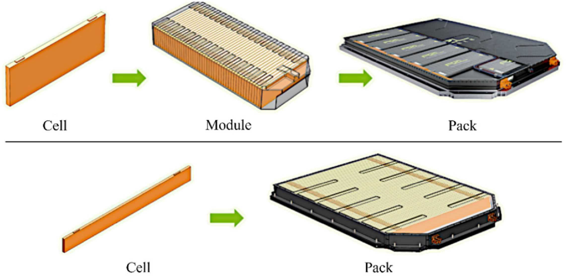
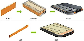
Battery architectures are commonly classified as module-to-pack, cell-to-pack, or hybrid. Module-to-pack systems integrate enclosed modules within a housing, facilitating maintenance but increasing inactive mass. Cell-to-pack approaches integrate cells directly into the load-bearing structure, improving packaging efficiency while increasing integration complexity. Concept selection depends on cost, production volume, maintenance strategy, and mass constraints (Reference Capasso, Iannucci, Patalano, Veneri and VitoloCapasso et al., 2024a; Reference Plewnia and TanPlewnia & Tan, 2024). Figure 1 illustrates the architectural distinction between module-to-pack and cell-to-pack configurations.
Conceptual comparison between module-to-pack (top) and cell-to-pack (bottom) battery architectures (Grace Stubbins, 2026)
2. Problem statement
The electrification of refrigerated transport has become a key enabler for reducing noise and emissions in urban logistics. AddVolt pioneered this transition by developing the world’s first plug-in hybrid system for refrigerated trucks, allowing full electric operation of the cooling unit during loading, unloading, and standby conditions. While the first-generation solution successfully demonstrated environmental and acoustic benefits, market feedback revealed opportunities for improvement in cost efficiency, scalability, and modularity.
2.1. Limitations
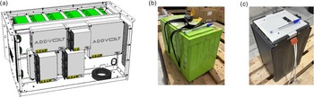
The previous generation of AddVolt’s powerpack, serving as the baseline solution, followed a conventional module-to-pack architecture, in which electrochemical cells were enclosed within rigid structural modules (see Figure 2a and 2b) subsequently integrated into a pack housing. This configuration imposed a relatively low configurational resolution, as energy and power ratings were constrained by the fixed module definition. This limited adaptability to different vehicle requirements and reduced flexibility in tailoring capacity for multiple applications. Moreover, the integration of the power electronics subsystem within the same enclosure created architectural interdependence between electrical and structural domains, restricting independent subsystem upgrades and complicating future platform evolution.
(a) Baseline powerpack configuration (module-to-pack); (b) Structural battery module used in the baseline configuration; (c) Electrically pre-configured cell-group for cell-to-pack configuration
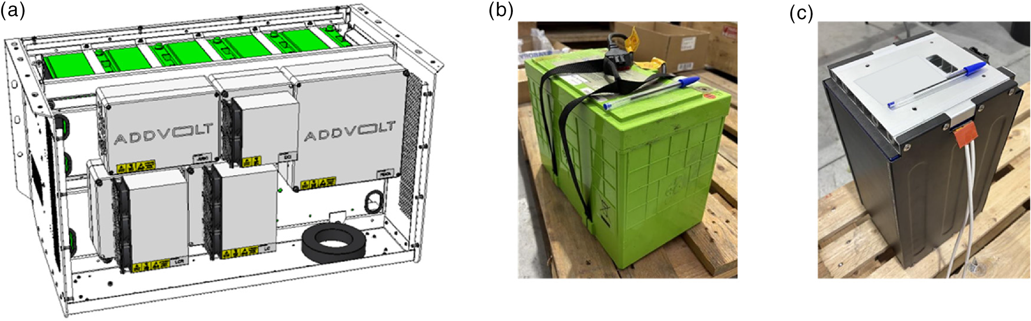
To address these limitations, a cell-to-pack architecture was adopted, in which electrochemical cells are grouped according to a specification defined to meet the required voltage and power resolution, without the use of independent structural module housings. These cell groups (see Figure 2c) are supplied as electrically pre-configured assemblies with minimal protective casing and are directly secured to the pack’s load-bearing structure. Consequently, global structural loads are carried by the primary frame rather than by intermediate module casings. Furthermore, a modular system architecture was adopted, in which the power electronics subsystem was decoupled from the battery pack and implemented as an independent module.
This redesign aligned with a broader objective of creating a cost-competitive, scalable product platform capable of supporting multiple vehicle configurations and future component upgrades.
The main features of the baseline AddVolt powerpack are present in Table 1.
Baseline AddVolt powerpack specifications

2.2. Objectives
The main goals of the battery pack redesign are:
-
• Improve cost competitiveness through simplified assembly and part reduction.
-
• Increase energy and power density by adopting a prismatic cell-to-pack configuration
-
• Enhance modularity and scalability for high-volume automated manufacturing.
-
• Separate functional domains (battery and electronics subsystems) to simplify maintenance and enable independent design iteration.
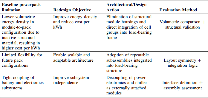
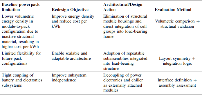
Table 2 summarises the logical mapping between baseline limitations, redesign objectives, and architectural decisions.
Mapping between baseline limitations, redesign objectives, and architectural decisions adopted in the development process
2.3. Design requirements and constraints
The development of the new battery pack was guided by operational, safety, and durability requirements defined by AddVolt to ensure performance and compliance with automotive standards.
Electrically, the system must operate within 300–550 V, ensuring that failure conditions do not cause fire, electrical arcing, or external surface temperatures above 200 °C. Thermal performance is equally critical: battery cell temperature must remain within adequate operating limits to ensure safety and longevity, with reliable performance from –30 °C to 60 °C during both charging and discharging. These conditions impose strict demands on cooling plate design and overall thermal uniformity.
Structurally, all components must resist corrosion for 1000 h under ISO 9227/ASTM B-117 conditions and maintain integrity under vibration and impact typical of commercial vehicles, while preserving accessibility for assembly and maintenance. Modularity was also defined as a key design requirement, enabling flexibility in system configuration, ease of maintenance, and scalability for future product variants.
The new concept aimed to enhance manufacturability and system integration while maintaining the functional capabilities of the previous generation. Design targets included a maximum discharge power of 20 kW, an average discharge power of 15 kW, and an energy capacity in the range of 30–40 kWh—with 40 kWh adopted for performance evaluation.
These specifications defined the design envelope and boundary conditions that guided the mechanical and thermal development of the new architecture.
3. Materials and methods
3.1. Redesign methodology
The redesign was conducted using a simulation-driven, iterative framework grounded in Design for Manufacturability and Assembly (DfMA) principles, aiming to achieve structural stiffness, modular adaptability, and manufacturing feasibility.
The process began with a conceptual definition phase in which system-level requirements—mechanical envelope, voltage and power range, thermal limits, and safety constraints—were translated into a baseline geometric model integrating the structural frame, fixation interfaces, and enclosure geometry.
Structural validation was performed using finite element analysis, which served as the primary feedback mechanism throughout the design cycle. Each iteration included static, modal, harmonic, and transient analyses to identify critical stress and displacement regions requiring reinforcement or redesign.
Thermal simulations were conducted to evaluate temperature distribution within the cell groups and the effectiveness of the liquid-cooling plates under representative operating conditions. Structural and thermal results informed geometric adjustments such as material redistribution, fixation refinement, and cooling-channel optimisation.
This iterative loop—comprising CAD modelling, numerical analysis, and design refinement (Figure 3)—guided convergence toward a configuration meeting mechanical, thermal, and manufacturing requirements while supporting future scalability. The numerical analyses were employed as design-support tools during this early development stage, enabling informed architectural and structural decisions prior to prototype manufacturing. They are not intended to replace experimental validation, which will be conducted in subsequent phases through physical testing under representative operational and regulatory conditions.
Simulation-driven iterative design workflow, from requirement definition to validation through structural and thermal analyses

3.2. Materials and structural concept
The battery pack architecture adopts a cage-like structural concept composed of welded tubular members and sheet-metal reinforcements, intended to achieve a high stiffness-to-weight ratio and withstand vibration loads typical of vehicular applications. Enclosure panels were designed to act as secondary structural elements, providing protection for internal components while ensuring accessibility for maintenance and inspection.
The primary load-bearing frame and enclosure panels were manufactured from stainless steel 304L, selected for its mechanical strength, weldability, and corrosion resistance. Cooling plates were produced from Al 6061-T6 to ensure adequate thermal conductivity, while copper busbars provided efficient electrical interconnection. Electrically insulating POM spacers were employed to maintain cell positioning and dielectric separation. Material selection prioritised structural robustness, thermal compatibility, and compatibility with conventional manufacturing processes.
Thermal management is achieved through aluminium cooling plates positioned between the grouped cells and integrated into the structural assembly. This configuration defines the thermal interfaces considered in the subsequent numerical analyses.
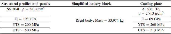
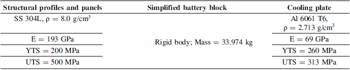
The material properties used in the structural simulations are summarized in Table 3.
Materials properties considered for structural simulations
3.3. Structural simulation
The structural assessment of the battery pack was performed through the finite element method, a numerical analysis technique to calculate an approximate solution in compliance with international vibration and mechanical shock regulations, using the commercial software ANSYS Mechanical. The analysis workflow consisted of four interconnected stages: (1) a static structural analysis to establish the pre-stressed state due to gravitational loading; (2) a modal analysis to extract the natural frequencies and corresponding mode shapes; (3) to simulate vibration during transport following the UN 38.3 standard (United Nations, 2023); and (4) a transient response analysis to evaluate the structural behavior under shock loading, in accordance with UN ECE Regulation No. 100 Revision 3 (United Nations, 2022), for M2 and N2 category vehicles. A fixed support was added to the geometry’s features designed for vehicle or test machine’s fixation. Tables 4 and 5 illustrate the input acceleration data for the vibration and shock testing, accordingly:
Input acceleration data for each of three mutually perpendicular mounting positions of the model, for the harmonic response analysis

Input acceleration data for the transient response analysis

Prior to meshing, the model geometry was simplified by removing non-structural features to reduce computational cost while preserving mechanical accuracy. Sheet metal parts were idealized as shell elements and volumetric parts as solids, with a 3 mm mesh refinement around holes of 20 mm diameter or less. The final model exhibited a majority of quadrilateral and hexahedral type elements, an average quality of 0.89, an average aspect ratio of 1.5 and a total of 800,735 degrees of freedom.
3.4. Thermal simulation
Thermal simulations were performed in ANSYS Fluent to assess the temperature distribution and heat-transfer behavior within the battery pack enclosure. The computational model included all major heat-generating components—specifically the battery cells—as well as the structural and enclosure elements. The assembly consists of a stainless-steel supporting frame that accommodates the battery cells, liquid-cooling plates, and cover panels. Heat conduction was modelled through all solid components, while convective and radiative exchanges with the external environment were considered. Natural convection within the internal air volumes of the enclosure was also included to capture the overall thermal response of the system under steady-state conditions.
A dissipated power of 153 W was considered for each battery module. Furthermore, convective boundary conditions were applied to the external surfaces, with an ambient heat transfer coefficient of 10 W/m2·K and a room temperature of 60 °C, corresponding to the maximum specified operating condition. Radiation between internal surfaces was considered negligible. Regarding the liquid refrigeration system running through the channels in the aluminum plate, a temperature of 20 °C and a flow rate of 0.1 kg/s were considered for the water inlet.
4. Results and discussion
This chapter presents the final battery-pack design obtained through the described iterative methodology, together with the results of the structural and thermal simulations. The design is assessed in terms of power and energy density, mechanical stiffness, and thermal uniformity, which represent key indicators of its performance.
4.1. Architecture and design features
The developed battery-pack architecture adopts a structurally integrated cell-to-pack concept within a welded stainless-steel cage that houses twelve prismatic cells, the liquid-cooling assembly, and two lateral subsystems: the power-electronics module and the chiller unit. The cage serves as the primary load-bearing structure, comprising welded tubular members reinforced by transverse and lateral beams to ensure torsional stiffness and uniform load distribution, while dedicated mounting plates provide structural independence from the vehicle body.
Within this frame, the cells are arranged in four groups of three, each mechanically and thermally coupled to a dedicated liquid-cooling plate. The cooling circuit is routed beneath the cell layer, whereas the busbar network is positioned above it, maintaining physical separation between thermal and high-current electrical domains.
The power electronics module is laterally mounted to the cage and thermally integrated into the cooling circuit, while the chiller unit is supported on the opposite side. Externally, stainless-steel 304L panels attached via threaded inserts and bolts provide environmental protection and contribute to global stiffness, with silicone seals ensuring vibration damping and sealing.
Beyond structural and thermal validation, manufacturability and assembly considerations were embedded in the architectural definition. All structural components were designed for production using conventional industrial processes, including welded steel profiles, laser-cut and bent sheet-metal panels, and machined POM spacers, avoiding specialized or proprietary manufacturing techniques. Assembly relies on standard fasteners and conventional tooling.
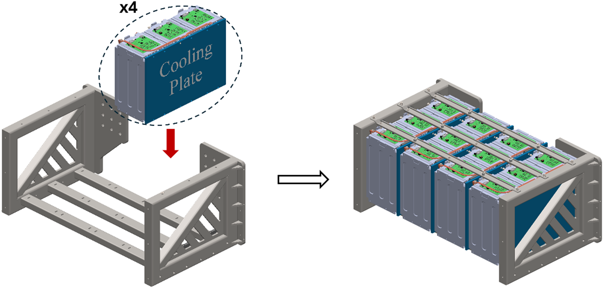
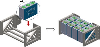
The pack architecture is organized around four repeated subassemblies, each consisting of three electrically grouped cells mechanically coupled to a dedicated cooling plate prior to integration into the main frame. This repeated modular structure simplifies assembly sequencing and supports scalable production. Maintenance accessibility is enabled by allowing the removal of individual three-cell-group cooling subassemblies without complete pack disassembly. Functional modularity is ensured through mechanically independent lateral mounting of the power electronics and chiller units, permitting subsystem upgrades without structural redesign of the battery frame. The integration sequence of the four cooling–cell subassemblies into the load-bearing frame is illustrated in Figure 4.
Integration sequence of the repeated three-cell-group/cooling plate subassemblies into the primary load-bearing frame
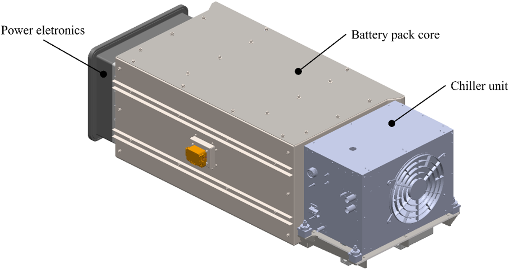
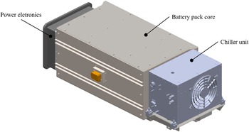
The complete redesigned, including all auxiliary modules, measures 1592 × 646 × 534 mm with a total mass of 697 kg, encompassing the battery cells, structural frame, chiller, and power electronics unit (see Figure 5).
Redesigned battery pack with power eletronics module (left) and chiller (right) attached
4.2. Structural simulation
The structural simulations were performed on a preliminary version of the battery pack assembly, prior to the implementation of the final reinforcements and fixation supports mentioned in Section 4.1. The numerical analyses identified areas of stress concentration and local deformation, which guided the subsequent design refinements integrated into the final configuration.
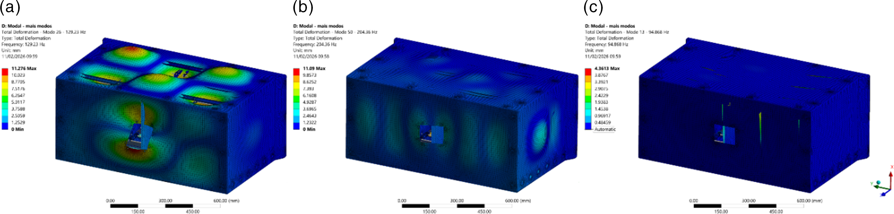
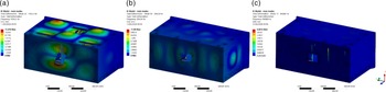
A total of 81 mode shapes were calculated from 0 to 300 Hz. From the effective mass ratio output, modes 26, 50 and 13 were the most relevant for x (vertical), y (transverse) and z (longitudinal) directions (see Figure 6), respectively. Lower order modes were a result of a low sheet metal casing’s stiffness. The upper frequency limit, 300 Hz, was defined to encompass all significant resonances within the operational and testing frequency range required by the UN 38.3 vibration’s standard. Thus, the mode-superposition method was used to couple the modal and the linear harmonic’s analysis and only modes with a modal effective mass above 0.30 were saved for computation’s efficiency.
Mode shapes with the highest effective mass ratio in the (a) x, (b) y and (c) z directions
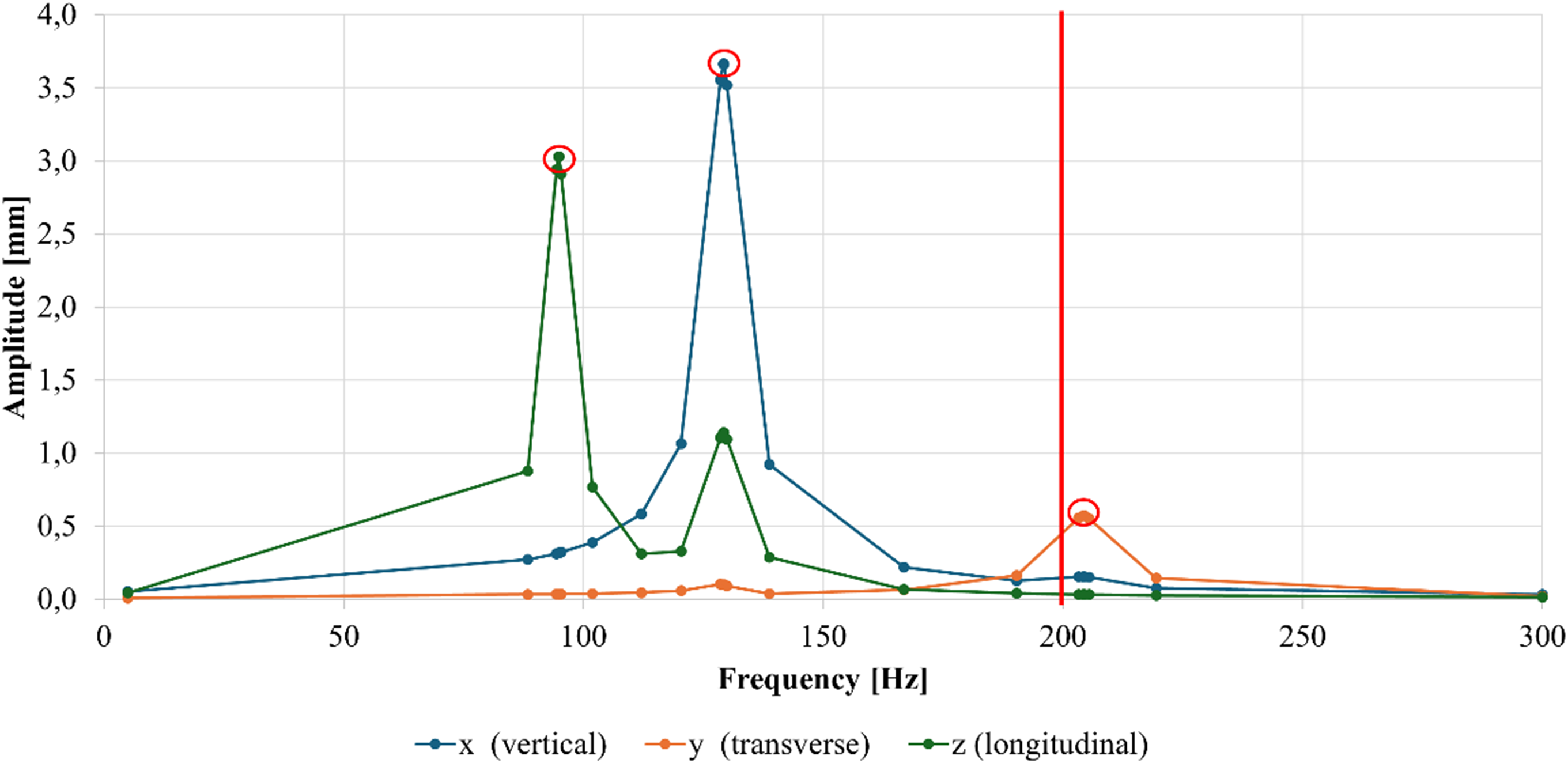
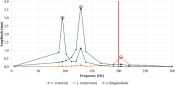
The frequency response results confirmed resonant stress amplification at the identified modal frequencies, as evidenced by peak displacements in the Bode plots below the 200 Hz maximum frequency specified by the standard (see Figure 7). For the X direction, von Mises stresses of 550 MPa were localized at the manual service disconnect opening edges. A mesh convergence study (10 to 3 mm element size) demonstrated an exponential stress increase, confirming the presence of a stress singularity. The maximum displacement was 3.5 mm at the top sheet metal.
For the Y direction, a peak response occurred at 204 Hz. The maximum displacement was 0.5 mm at the chiller-side sheet metal, while stress concentrations (≈550 MPa) were located at top U-profile reliefs. For the Z direction, the most demanded components were similar, with a maximum displacement of 3.0 mm and stress values between 500 and 940 MPa concentrated around battery connection holes.
Frequency response Bode plots for the x (vertical), y (transverse) and z (longitudinal) directions
The transient response analysis was linked to the modal analysis results. For the Y direction, a maximum directional deformation of 0.13 mm was calculated at the chiller’s side lateral panel, without compromising assembly integrity. A maximum equivalent stress of 110 MPa was calculated at top U-shaped profile bend reliefs. For the Z direction, a maximum directional deformation of 0.41 mm was calculated at the front sheet metal and a maximum equivalent stress of 330 MPa occurred at the top U-shaped profile, concentrated around the battery-connection’s holes.
Both harmonic and transient analyses demonstrated that stiffness reinforcement in the top U-profiles and outer sheet metal panels would reduce deformation and stress concentrations, ensuring compliance with international vibration and shock standards. Specifically, bend relief’s design optimization for top U-profiles and additional fixation points for the outer sheets. Additionally, among the top U-shaped profiles and outer panels, as demonstrated by a mesh parametrization study, there was evidence of stress singularities, and some bodies were defined with a rigid stiffness behavior without considering the dampening and contact stiffness it would thereby increase at assembly level, which minimized the risk taken from the design point of view.
Further non-linear analysis could be performed to evaluate plastic behavior, though the present linear analyses, taking part of a design iteration prior to experimental testing and validation for production, were sufficient for design optimization and experimental validation.
4.3. Thermal simulations
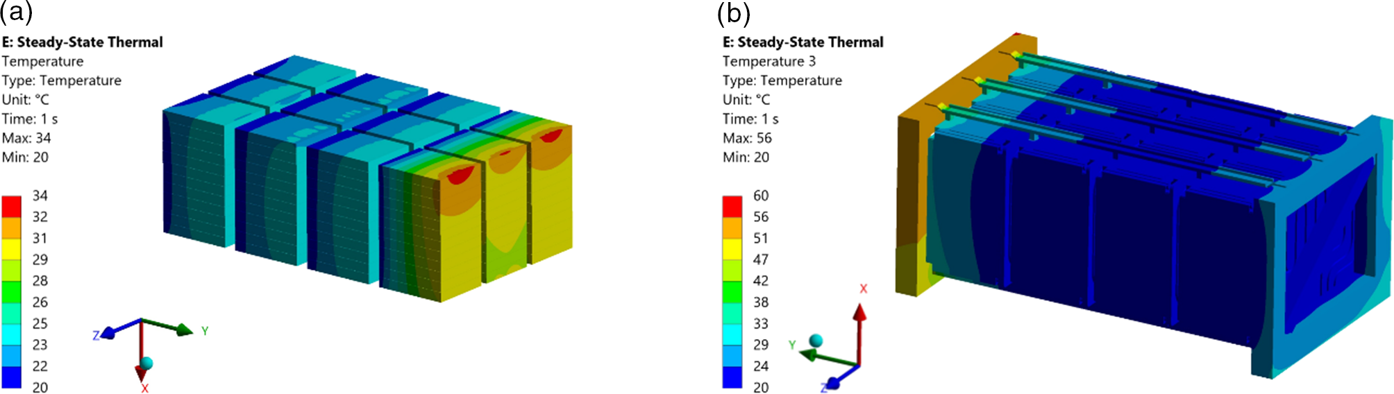
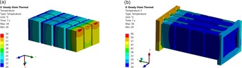
The thermal simulation results indicated that the system maintains stable and safe operating conditions under the defined boundary parameters, as shown in Figure 8. The maximum temperature recorded within the model was approximately 60 °C, corresponding to the imposed ambient temperature. The cooling water temperature remained nearly constant at 20 °C, showing minimal rise throughout the simulation and confirming the effectiveness of the heat-exchange system.Consequently, the battery cells were kept well below the critical limit specified by the cell manufacturer (≈80 °C), demonstrating that the thermal management configuration successfully controls heat accumulation.
Overall, the results confirm that the proposed enclosure and cooling system designs efficiently mitigate temperature rise within the battery pack, maintaining all components within their recommended operational thermal range.
Temperature distribution across (a) the battery cells and (b) the battery pack
4.4. Design assessment and performance metrics
From a structural perspective, the welded stainless-steel cage satisfied the vibration and mechanical-shock requirements defined by UN 38.3 and UN ECE R100 Rev. 3. The closed-frame configuration ensures uniform load distribution and low global deformation under dynamic excitation, while bolted interfaces allow partial disassembly without compromising the integrity of the primary frame.
Thermal simulations confirmed that the four liquid-cooling plates—each coupled to a three-cell group—maintain uniform temperature distribution within the pack. All cells remained below the manufacturer’s maximum temperature limit under representative operating conditions, indicating sufficient cooling capacity. Functionally, the architecture supports subsystem modularity through lateral mounting of the power electronics and chiller units, enabling independent development and replacement. The repeatable three-cell-group subassembly also provides scalability in installed capacity, allowing adaptation to different energy and power requirements within the same structural platform.
For comparison with AddVolt’s previous solution—which did not incorporate active liquid cooling—the chiller and its support structure were excluded from the density calculations. The resulting effective mass (646 kg) and volume (0.415 m3) were used to compute the metrics in Table 6.
The developed design exhibits a moderate reduction in gravimetric power and energy densities due to increased structural mass but achieves a significant improvement in volumetric energy density. This indicates that the redesigned architecture provides superior packaging efficiency, favouring applications where installation volume is more critical than overall weight.
Performance metrics comparison between AddVolt’s standard powerpack and developed solution

5. Conclusions and future works
This work presented the design and simulation-based development of a cell-to-pack battery system for AddVolt’s hybrid-electric transport platform. The redesigned architecture addresses key limitations of the previous powerpack, particularly configurational rigidity, subsystem coupling, and limited scalability. The solution integrates the battery cells, liquid-cooling system, and power-electronics interfaces within a welded stainless-steel load-bearing cage, forming a compact and modular assembly.
An iterative simulation-driven methodology combining finite-element and thermal analyses was used to refine the structural and thermal configuration prior to prototyping. Structural simulations identified regions requiring reinforcement and additional fixation, while thermal analyses confirmed that cell temperatures remained within operational limits under representative boundary conditions. The results demonstrate a trade-off between gravimetric and volumetric performance: although structural reinforcement and integrated cooling increase mass, the redesigned layout improves volumetric efficiency and packaging flexibility.
The numerical analyses served as design-support tools during early development and do not replace experimental validation. A physical prototype will undergo bench testing, including charge–discharge cycling and structural vibration testing under applicable regulatory profiles. Experimental results will enable correlation with numerical predictions and support further model refinement.
Acknowledgement
This work was developed within the scope of the project “NGS – New Generation Storage” [C644936001-00000045], financed by PRR – Plano de Recuperação e Resiliência under the Next Generation EU from the European Union.






 Open access

