


Introduction
Workers performing manual material handling repetitively lift objects in order to move freight from distribution centers to trucks, trucks to pallets, and pallets to shelves. In the process, they perform motions such as lifting, pushing, pulling, holding, and carrying objects. These tasks are performed by 2.6 million workers in the United States each day (Bureau of Labor Statistics, 2016a). These motions can be metabolically costly or can cause overexertion, both of which can lead to pain and injuries (Texas Department of Insurance, 2009; Liberty Mutual Research Institute for Safety, 2016). Injuries from manual material handling can occur in almost any part of the body, including the back, shoulders and arms, and legs. In total, these occur at the rate of 297.8 per 10,000 workers per year (Bureau of Labor Statistics, 2016b), and back injuries occur the most frequently, accounting for 20% of the total (Texas Department of Insurance, 2009). In addition to causing medical issues for workers, injuries from lifting cost companies billions of dollars in reparations and the loss of over tens of millions of productive days (Elliott, Reference Elliott2015; Liberty Mutual Research Institute for Safety, 2016).
Recently, exoskeletons have been introduced as a solution to these increasing health issues in the workplace (Lotz et al., Reference Lotz, Agnew, Godwin and Stevenson2009; Wehner et al., Reference Wehner, Rempel and Kazerooni2009; Luo and Yu, Reference Luo and Yu2013). To offload the back during lifting, back exoskeletons have become more commonplace. These can be classified broadly as passive (unpowered) or active (powered). Passive exoskeletons provide a fixed torque profile as a function of the hip angle, while active exoskeletons can modulate their torques to match the wearer’s motion. As passive exoskeletons do not use any external power sources such as motors or batteries, they are generally lighter and simpler than active exoskeletons. Numerous examples of both kinds have been found in the literature. One review reported seven passive back exoskeletons (de Looze et al., Reference de Looze, Bosch, Krause, Stadler and O’Sullivan2016), and several designs have been published since then (Lamers et al., Reference Lamers, Yang and Zelik2017; Baltrusch et al., Reference Baltrusch, van Dieen, Koopman, Naf, Rodriguez-Guerrero, Babič and Houdijk2020). Similarly, there have been many active back exoskeletons; some recent examples include Huysamen et al. (Reference Huysamen, de Looze, Bosch, Ortiz, Toxiri and O’Sullivan2018), Ko et al. (Reference Ko, Lee, Koo, Lee and Hyun2018), Toxiri et al. (Reference Toxiri, Koopman, Lazzaroni, Ortiz, Power, de Looze, O’Sullivan and Caldwell2018), Yang et al. (Reference Yang, Huang, Hu, Yu, Zhang, Zhou, Carriero, Yue and Su2019).
In this paper, we focus on passive back exoskeletons. A passive back exoskeleton stores energy elastically while a person bends forward during a lift, then returns that energy to the wearer to help them stand up straight again. These exoskeletons have employed a variety of different materials for storing energy, including rubber bands, composites, torsional springs, gas springs, and coil springs (Frost et al., Reference Frost, Abdoli and Stevenson2009; Hasegawa and Muramatsu, Reference Hasegawa and Muramatsu2013; Bosch et al., Reference Bosch, van Eck, Knitel and de Looze2016; Lamers et al., Reference Lamers, Yang and Zelik2017; Näf et al., Reference Näf, Koopman, Baltrusch, Rodriguez-Guerrero, Vanderborght and Lefeber2018; Baltrusch et al., Reference Baltrusch, van Dieen, Koopman, Naf, Rodriguez-Guerrero, Babič and Houdijk2020), and use various mechanisms to couple the forces from the exoskeleton to the body. In the following review, passive back exoskeletons will be separated into two different categories for further discussion: (a) elastic bands or composites, and (b) gas or metal springs.
Exoskeletons with Elastic Bands or Composites
Rubber or elastic bands are a common technique for passively returning energy to the wearer due to their high energy density. Many previous exoskeletons utilized rubber in conjunction with rigid support structures to relieve the back muscles (Abdoli-E et al., Reference Abdoli-E, Agnew and Stevenson2006; Wehner et al., Reference Wehner, Rempel and Kazerooni2009; Ulrey and Fathallah, Reference Ulrey and Fathallah2013). Of the exoskeletons using elastic bands for energy storage, the personal lift augmentation device (PLAD) has been studied the most extensively (Abdoli-E et al., Reference Abdoli-E, Agnew and Stevenson2006; Abdoli-E and Stevenson, Reference Abdoli-E and Stevenson2008; Frost et al., Reference Frost, Abdoli and Stevenson2009; Whitfield et al., Reference Whitfield, Costigan, Stevenson and Smallman2014). On the PLAD, a hip belt is worn, which has a pelvic spacer bar protruding from the back. Four elastic bands connect the spacer bar to the shoulders, while one band connects the spacer bar to the shin bone on each leg. As the wearer bends forward, the elastic bands stretch, building a restoring moment.
One of the more recent exoskeletons developed by Lamers et al. (Reference Lamers, Yang and Zelik2017) also uses elastic bands. As compared to the PLAD, it does not use a pelvic spacer on the back of the hips, but rather places the elastic against the body. Two crossed-over elastic bands connect from the upper-body interface to the lower-body interfaces, which are located on the thighs instead of below the knee (as on the PLAD). Two commercial devices use elastic bands: the HeroWear Apex (HeroWear, 2020) and the Auxivo LiftSuit (Auxivo, Reference Auxivo2020).
Several devices have also used composites. One device used a combination of elastic bands and a fiberglass rod acting in bending (Barrett and Fathallah, Reference Barrett and Fathallah2001). A recent device uses a flexible composite rod on each side of the body as a leaf spring to provide a restoring force (Ergosanté Solutions Ergonomiques, 2020).
Exoskeletons with Gas or Metal Springs
Metal springs or gas springs have also been incorporated into a few passive exoskeleton designs (Wehner et al., Reference Wehner, Rempel and Kazerooni2009; Ulrey and Fathallah, Reference Ulrey and Fathallah2013; Bosch et al., Reference Bosch, van Eck, Knitel and de Looze2016; Zhang et al., Reference Zhang, Kadrolkar and Sup2016; Kazerooni, Reference Kazerooni2018). The Bending Non-Demand Return weight transfer device implements torsional springs at the hip to apply a torque to the wearer during lifting (Ulrey and Fathallah, Reference Ulrey and Fathallah2013). Wehner et al. (Reference Wehner, Rempel and Kazerooni2009) built a passive exoskeleton that uses a coil spring and cable system in conjunction with a star-shaped cam to modulate the restoring moment at the hip. Another exoskeleton, the passive spine exoskeleton, implemented extension springs along the chest and legs with a rotating cam to apply push and pull forces (Zhang et al., Reference Zhang, Kadrolkar and Sup2016). The Laevo, one of the few commercially available exoskeletons, uses a gas spring in conjunction with a cam (Bosch et al., Reference Bosch, van Eck, Knitel and de Looze2016; Baltrusch et al., Reference Baltrusch, van Dieën, van Bennekom and Houdijk2018). Another commercial exoskeleton, backX (SuitX, Inc., Berkeley, CA), also uses gas springs to provide a restoring moment at the hip (Kazerooni et al., Reference Kazerooni, Hacker and Chen2011).
Finally, another recent passive exoskeleton used a carbon fiber beam in the back and springs with a cam in the legs (Näf et al., Reference Näf, Koopman, Baltrusch, Rodriguez-Guerrero, Vanderborght and Lefeber2018). The inclusion of the flexible beam with a slider in the back was found to permit an increased range of motion; however, the springs at the legs perform the majority of energy storage and return. The lower leg mechanism was measured to return only around 71% of its stored energy, while the carbon fiber in the back returned nearly all of it (Näf et al., Reference Näf, Koopman, Baltrusch, Rodriguez-Guerrero, Vanderborght and Lefeber2018). This exoskeleton also used a rigid mechanism to achieve a discrete pivot at the hip.
Our Work
We investigated the use of a composite leaf spring made of carbon fiber as the sole energy storage element in the exoskeleton. Our device’s design uses flexible rods that stay behind the body from the back to the legs; this requires accommodating the kinematic difference between the exoskeleton frame and the hip joint’s motion. Our exoskeleton achieves this with sliders and soft interfaces to apply forces perpendicularly to the body.
In this work, we first present a comprehensive quantitative comparison of the different possible methods of storing energy and returning it to the wearer in terms of their density, hysteresis, and cycle life (Section “Exoskeleton Comparative Design Analysis”), allowing future exoskeleton designers to select the most beneficial materials. We also calculate the torques needed to statically support the torso at different angles. We then present the design of a novel exoskeleton, the VT-Lowe’s exoskeleton, that assists the back during lifting (Section “Exoskeleton Design”). Our exoskeleton design incorporates flexible beams to permit the body to move freely in both bending and twisting. In a previous study (Alemi et al., Reference Alemi, Geissinger, Simon, Chang and Asbeck2019) the exoskeleton was shown to reduce the activity of the back muscles and be comfortable during lifting. In this work, we present results quantifying the exoskeleton’s mechanical behavior and its effect on the body during lifting (Section “Results and Discussion”).
Methods
Exoskeleton Comparative Design Analysis
Design goals
In this section, we seek to establish a set of goals for the design of a lift-assist exoskeleton. We provide these as a basis for comparison, recognizing that different applications may have different specifications. First, we compute the torques needed for an exoskeleton to relieve the weight of the torso. That is, if a person bends forward at the waist by some angle, the exoskeleton would completely support the weight of their torso, such that their trunk muscles can be relaxed if they move quasi-statically. Then, the trunk muscles can be used to lift a mass equivalent to that of the torso, and experience forces similar to what they would experience if the person was bending forward without a load. Of course, if an exoskeleton provides a smaller torque than this, then the back muscles will still have to exert effort. Conversely, if the exoskeleton creates a torque at any point during a bend that is greater than that required to support the torso, then the wearer will have to use their stomach muscles to curl against the exoskeleton when they bend forward.
To determine the torques and energy storage that should be provided by an exoskeleton, we must first determine the torque and energy required to lift the torso back to vertical from an inclined position. Anthropomorphic data from Huston (Reference Huston2009) was used to calculate the torque to support the torso if it was tilted forward by a given angle in torso flexion, and to calculate the potential energy needed to raise the torso back to vertical, and is shown in Figure 1. This analysis assumes the back remains straight during the lift, which is not strictly true in most cases (Dolan and Adams, Reference Dolan and Adams1993b). The results in Figure 1 are similar to those measured in several other studies (Schipplein et al., Reference Schipplein, Trafimow, Andersson and Andriacchi1990; Lindbeck and Arborelius, Reference Lindbeck and Arborelius1991; Tsuang et al., Reference Tsuang, Schipplein, Trafimow and Andersson1992; Dolan et al., Reference Dolan, Mannion and Adams1994), although still other studies found smaller values with peak torques around 80 Nm (Bazrgari et al., Reference Bazrgari, Shirazi-Adl and Arjmand2007; Olson et al., Reference Olson, Li and Solomonow2009) for average-sized males. The equations for torque $ \tau $
and energy
$ \tau $
and energy $ U $
are:
$ U $
are:
 $$ \tau =\sin {\theta}_{torso}\sum \limits_i{m}_i\hskip0.1em g\hskip0.1em {r}_i, $$
 $$ U=\left(1-\cos {\theta}_{torso}\right)\sum \limits_i{m}_i\hskip0.1em g\hskip0.1em {r}_i, $$
The torque needed to support the torso if it is tilted forward by a given angle (torso flexion) (a), and the energy needed to raise the torso back to a vertical position after tilting forward by a given angle (b). Two sets of curves correspond to data for males and females. Within each set of curves, the top boundary corresponds to the 95th percentile in both height and weight, the middle line is the 50th percentile for height and weight, and the bottom boundary is the 5th percentile for height and weight. A 50th percentile male has a mass of 80.42 kg and is 1.76 m tall, while a 50th percentile female has a mass of 59.85 kg and is 1.62 m tall (Huston, Reference Huston2009). In each graph, the torso angle (torso flexion) at the deepest portion of a lift is plotted for freestyle, squat, and stoop lifting styles. Each band corresponds to the mean and mean $ \pm $
SD from Section “Results and Discussion”.
$ \pm $
SD from Section “Results and Discussion”.

where $ {\theta}_{\mathrm{torso}} $
is the torso flexion,
$ {\theta}_{\mathrm{torso}} $
is the torso flexion, $ {m}_i $
is the mass of body part
$ {m}_i $
is the mass of body part $ i $
,
$ i $
, $ {r}_i $
is the radius from the middle of the pelvis to the center of mass of body part
$ {r}_i $
is the radius from the middle of the pelvis to the center of mass of body part $ i $
, and
$ i $
, and $ g $
is the acceleration due to gravity. The sum was calculated over the head plus neck, trunk, and arms plus hands, which are connected at the radius of the shoulders and assumed to hang straight down.
$ g $
is the acceleration due to gravity. The sum was calculated over the head plus neck, trunk, and arms plus hands, which are connected at the radius of the shoulders and assumed to hang straight down.
The graphs show a wide range of required torque and energy, depending on the mass and height of the person. The peak torso flexion angle will also vary based on the object height and type of lift. Due to the differing peak torso flexion angles combined with the sinusoidal shape for the torque, a 50th percentile person (either male or female) doing a squat lift requires 85.3% of the torque of a freestyle lift, while a stoop lift requires 111.1% of the torque of a freestyle lift. Thus, exoskeletons designed to perfectly support freestyle lifting will be slightly over-powered for squat lifting, and slightly under-powered for stoop lifting.
The analysis that went into Figure 1 should be considered as a point of reference, and the torques needed by a back exoskeleton may differ somewhat from these values. In practice, people adopt a wide range of postures in daily life, and postures with smaller torso angles will have lower torques needed to support the torso. Additionally, torques of up to 50 Nm are provided by passive structures in the back (Dolan et al., Reference Dolan, Mannion and Adams1994; Bazrgari et al., Reference Bazrgari, Shirazi-Adl and Arjmand2007; Olson et al., Reference Olson, Li and Solomonow2009; Koopman et al., Reference Koopman, Toxiri, Power, Kingma, van Dieën, Ortiz and de Looze2019b), and this will reduce the torque needed by an exoskeleton unless the wearer is extremely flexible (Dolan and Adams, Reference Dolan and Adams1993a). Thus, it may be beneficial in most circumstances for a back exoskeleton to provide smaller torques than those in Figure 1.
For subsequent analysis, we use an energy of 100 J, a round number which nearly corresponds to a 50th percentile male bending their torso forward 64° from vertical per the analysis in Figure 1 (107 J). This angle (64°) corresponds to the torso flexion angle used when lifting an object from close to the floor with a freestyle lift (Section “Results and Discussion”). The 100 J number can be scaled to other torso angles and body sizes based on the graphs.
Beyond the torque, there are other desired properties for a wearable device. Since an exoskeleton will be worn all day, a smaller mass will result in lower fatigue for the wearer. Also, it may be important to minimize the volume and protrusion from the body to reduce interference with the environment. For example, in an industrial setting, it may become necessary for the wearer to pass by operating machinery or fit into small spaces such as under shelves or in a tractor trailer. Different applications will have different specific requirements for both mass and protrusion from the body.
Finally, the exoskeleton needs to be able to endure the stresses of repetitive lifting. For example, Marras et al. (Reference Marras, Granata, Davis, Allread and Jorgensen1997) reported an estimated 166 lifts/hr for workers performing palletizing. Extrapolating this to a 40 hr work week and 50 work weeks per year results in 332,000 lifts per year which could be assisted by an exoskeleton, assuming a laborer is wearing the exoskeleton every shift and lifting consistently. If an exoskeleton withstands usage for three years at this rate, this corresponds to $ {10}^6 $
lifts. Practically, this is likely an upper bound for an exoskeleton lifetime, since relatively few workers lift at 166 lifts/hr continuously. Another recent paper studying stockers in a commercial environment found an average of 41 bends/hr, which corresponds to a quarter of the previous numbers, or 83,000 bends per year (Geissinger et al., Reference Geissinger, Alemi, Simon, Chang and Asbeck2020).
$ {10}^6 $
lifts. Practically, this is likely an upper bound for an exoskeleton lifetime, since relatively few workers lift at 166 lifts/hr continuously. Another recent paper studying stockers in a commercial environment found an average of 41 bends/hr, which corresponds to a quarter of the previous numbers, or 83,000 bends per year (Geissinger et al., Reference Geissinger, Alemi, Simon, Chang and Asbeck2020).
Elastic mechanism considerations
Many materials or structures can be used to store energy and then return it. We investigated composites, titanium, gas springs, coil springs, and elastic bands to establish a design space based on constraints such as volume, mass, hysteresis, and cycle life. The specific materials evaluated in Sections “Elastic Mechanism Considerations,” “Hysteresis,” and “Cycle Life,” and their suppliers, are listed in Appendix A.
In Figure 2, we plot the volume and mass of different elastic mechanisms that will provide 100 J. The carbon fiber, fiberglass, and titanium calculations assume the materials were brought to 83% of the yield stress $ {S}_y $
(corresponding to a factor of safety of 1.2). Carbon fiber was also calculated and plotted for 50% of its yield stress, which corresponds to a longer cycle life (see Section “Cycle Life”). The coil and gas springs were taken to 90% of their maximum stroke length, and the rubber was taken to different values of elongation as specified below. Details about the energy storage calculations for all materials are found in Appendix A.
$ {S}_y $
(corresponding to a factor of safety of 1.2). Carbon fiber was also calculated and plotted for 50% of its yield stress, which corresponds to a longer cycle life (see Section “Cycle Life”). The coil and gas springs were taken to 90% of their maximum stroke length, and the rubber was taken to different values of elongation as specified below. Details about the energy storage calculations for all materials are found in Appendix A.
The relative mass versus volume of various materials that can be used to store energy in passive exoskeletons. Carbon fiber was calculated for both 83 and 50% of its yield stress, while fiberglass and titanium leaf springs were only calculated for 83% of their yield stress. Three different types of gas springs were tested, with different maximum forces as specified in the legend. The percentages for the natural gum rubber (NGR) indicate the percentage of their original length to which they were extended.
For three of the elastic mechanism types, carbon fiber, fiberglass, and titanium, there are two different loading conditions: a cantilevered beam with an endpoint load, and a cantilevered beam with an end moment load (represented by an x through the symbol). Cantilevered beams with point loads have a non-uniform stress distribution along the length of the beam, while a cantilevered beam with a moment applied at the end creates a uniform stress along the length of the beam and optimizes the stored energy per unit volume.
Different amounts of elongation of NGR (Durometer 40A) were compared for energetic return. Figure 2 demonstrates how increased elongation causes reductions in the mass and volume of the necessary rubber to achieve 100 J of energetic return. NGR can achieve up to 600 $ \% $
elongation before ultimate failure; however, the life span at those elongations is dramatically decreased. As such, Figure 2 only goes to 300
$ \% $
elongation before ultimate failure; however, the life span at those elongations is dramatically decreased. As such, Figure 2 only goes to 300 $ \% $
elongation. The stored energy in NGR was measured for 50 and 100% elongation, and calculated for 200 and 300% elongation, with details in Appendix A. Empirical measurements were also taken for the gas springs following the procedures in Appendix A.
$ \% $
elongation. The stored energy in NGR was measured for 50 and 100% elongation, and calculated for 200 and 300% elongation, with details in Appendix A. Empirical measurements were also taken for the gas springs following the procedures in Appendix A.
The heaviest and largest in volume mechanisms are the compression coil springs. Other types of springs such as extension springs were considered, but the mass and volume necessary to achieve 100 J were far beyond even the coil springs shown in Figure 2.
Out of the springs in Figure 2, the materials with the lowest mass and volume are carbon fiber and NGR. Some gas springs also had comparable mass and volume, depending on the specific model. Under moment loading to $ 0.83{S}_y $
, the carbon fiber is roughly comparable to the 200
$ 0.83{S}_y $
, the carbon fiber is roughly comparable to the 200 $ \% $
NGR. The NGR with 300
$ \% $
NGR. The NGR with 300 $ \% $
elongation has the lowest mass and volume.
$ \% $
elongation has the lowest mass and volume.
Hysteresis
Hysteresis is the loss of energy during the loading and the unloading of an elastic element. In the case of a passive back exoskeleton, the wearer bends forward and transfers potential energy to the exoskeleton, and thus loads the elastic element. When the wearer then stands back up, the elastic element unloads and returns the stored elastic energy to the wearer minus the losses due to hysteresis. Any hysteresis losses reduce the net benefit that the exoskeleton can provide during lifting. Additional losses can occur from the soft goods or from the human tissue displacing, since they both act as lossy springs in series between the skeleton and the exoskeleton (Asbeck et al., Reference Asbeck, De Rossi, Galiana, Ding and Walsh2014; Yandell et al., Reference Yandell, Quinlivan, Popov, Walsh and Zelik2017).
Carbon fiber, Fiberglass, Titanium, Gas springs, and NGR were tested using an Instron 4204 machine following the conditions as specified in Appendix B. After loading and unloading samples, the area under the loading and unloading curves was found using the trapezoidal integration method, and hysteresis was calculated. The results are shown in Table 1. Out of our materials of interest, titanium, carbon fiber, fiberglass, and NGR have the lowest amounts with $ <5\% $
hysteresis, and gas springs have the largest amount with approximately 15%. A stack of materials (e.g., carbon fiber beams) will have additional hysteresis beyond that of a single beam, since the layers will rub against each other when bent. However, both carbon fiber and fiberglass have low coefficients of friction,
$ <5\% $
hysteresis, and gas springs have the largest amount with approximately 15%. A stack of materials (e.g., carbon fiber beams) will have additional hysteresis beyond that of a single beam, since the layers will rub against each other when bent. However, both carbon fiber and fiberglass have low coefficients of friction, $ <0.25 $
and
$ <0.25 $
and $ 0.25-0.5 $
, respectively (Fitzer and Manocha, Reference Fitzer and Manocha1998; Gohil et al., Reference Gohil, Parikh, Patel, Patel, Deheri, Patel and Mehta2014).
$ 0.25-0.5 $
, respectively (Fitzer and Manocha, Reference Fitzer and Manocha1998; Gohil et al., Reference Gohil, Parikh, Patel, Patel, Deheri, Patel and Mehta2014).
Hysteresis values for various elastic mechanisms

Note: These values are for the specific materials tested in Appendix B; materials made by other manufacturers may have somewhat different values.
Abbreviation: NGR, natural gum rubber.
Cycle life
Understanding how the applied stress relates to the cycle life (fatigue life) of elastic mechanisms is important for designing an exoskeleton that can withstand long-term use. Table 2 presents a summary of the cycle life data for the elastic mechanisms of interest as found in the literature. The table shows the cycle life resulting when carbon fiber, fiberglass, and titanium are loaded to various fractions of their yield stress $ {S}_y $
. All of the materials except the gas springs were tested to a stress ratio of
$ {S}_y $
. All of the materials except the gas springs were tested to a stress ratio of $ R=0.1 $
, which means that a material is loaded to a maximum stress
$ R=0.1 $
, which means that a material is loaded to a maximum stress $ \sigma $
, and then the stress is reduced to a minimum of
$ \sigma $
, and then the stress is reduced to a minimum of $ 0.1\sigma $
such that it is still bent or extended, with the load still in the same direction, and then the material is loaded again. Carbon fiber, fiberglass, and titanium were loaded in bending, NGR was loaded in extension, and gas springs were loaded in compression.
$ 0.1\sigma $
such that it is still bent or extended, with the load still in the same direction, and then the material is loaded again. Carbon fiber, fiberglass, and titanium were loaded in bending, NGR was loaded in extension, and gas springs were loaded in compression.
Cycle life for materials of interest
Notes: Multiple entries are shown for each material to show how the cycle life varies with the maximum applied stress; the fraction of the yield stress $ {S}_y $
is shown. Several entries are shown with different yield strengths corresponding to the same cycle life because different papers cited gave different values. All NGR samples assume 0% initial strain with the exception of those denoted by an asterisk (*); the single asterisk (*) has a 200% initial strain with 200% elongation, and the double asterisk (**) has an initial strain of 250% and an additional 50% elongation. Cycle life is shown for carbon fiber, fiberglass, and titanium tested with a stress ratio of 0.1.
$ {S}_y $
is shown. Several entries are shown with different yield strengths corresponding to the same cycle life because different papers cited gave different values. All NGR samples assume 0% initial strain with the exception of those denoted by an asterisk (*); the single asterisk (*) has a 200% initial strain with 200% elongation, and the double asterisk (**) has an initial strain of 250% and an additional 50% elongation. Cycle life is shown for carbon fiber, fiberglass, and titanium tested with a stress ratio of 0.1.
Abbreviation: NGR, natural gum rubber.
Nitrogen gas springs vary from 125,000 to 2,000,000 cycles according to various suppliers; this value is highly dependent on the spring’s construction and manufacturer. Rubber’s lifetime increases substantially when the minimum stress endured is high. For example, if rubber is extended by 75% initially, and is further extended to 125% for a total of 50% elongation, the life cycle can increase by an order of magnitude compared to rubber starting a zero extension to 50% elongation (Mars and Fatemi, Reference Mars and Fatemi2006). Therefore, if fatigue life is the primary parameter, rubber should be used with a high initial tension.
Some care must be taken in combining the results shown in Table 2 with those shown in Figure 2. The calculations shown in Figure 2 assume a minimum safety factor of 1.2 or $ 0.83{S}_y $
, for the fiberglass and titanium. Most of the results in Table 2 show high cycle lifetimes occur at lower fractions of the yield stress. Also, the specific materials tested may be different between Table 2 and Figure 2. For example, the NGR in Figure 2 has a durometer of 40 A, while the NGR in Table 2 has a durometer of 50 A. Additionally, particular resins or epoxies used to fabricate fiberglass or carbon fiber could cause variations. Without mechanical testing performed on the exact materials, there is no way to confirm the exact number of life cycles for the mechanisms presented in Figure 2; however, the information presented is still valuable because it presents the relative magnitude of the cycle life for each material. The comparisons drawn from Table 2 are based on magnitude differences, which absorbs error due to variations that may occur based on exact material composition.
$ 0.83{S}_y $
, for the fiberglass and titanium. Most of the results in Table 2 show high cycle lifetimes occur at lower fractions of the yield stress. Also, the specific materials tested may be different between Table 2 and Figure 2. For example, the NGR in Figure 2 has a durometer of 40 A, while the NGR in Table 2 has a durometer of 50 A. Additionally, particular resins or epoxies used to fabricate fiberglass or carbon fiber could cause variations. Without mechanical testing performed on the exact materials, there is no way to confirm the exact number of life cycles for the mechanisms presented in Figure 2; however, the information presented is still valuable because it presents the relative magnitude of the cycle life for each material. The comparisons drawn from Table 2 are based on magnitude differences, which absorbs error due to variations that may occur based on exact material composition.
In summary, many of these elastic storage mechanisms are possible to use for passive exoskeletons depending on the requirements for weight, volume, hysteresis, and cycle life. Carbon fiber and NGR both exhibit a good combination of low weight and volume, low energy loss, and a possible high cycle life (assuming the maximum stress is chosen carefully). Based on this analysis and the fact that carbon fiber can also be used as a structural element, we used carbon fiber to store energy in our exoskeleton.
Exoskeleton Design
Overview of exoskeleton design
We next provide an overview of our exoskeleton design (Figure 3). The exoskeleton components can be categorized into two groups: (a) soft components, which come into contact with the wearer’s body, and (b) mechanical components which form the structure of and provide energy storage for the exoskeleton. As shown in Figure 3a, soft components include the chest harness (1), hip belt (2), thigh cuffs (3), and posterior support cushions ((8) in Figure 3b). The mechanical components are shown in Figure 3b, and they include carbon fiber beams along the back and back of the legs (4), a back slider assembly (5) which includes an “X”-shaped structure that extends to the wearer’s shoulders and sides of their hips (6), a central hip block (7, close up view in Figure 3d), and leg sliders (9). All of the mechanical elements are on the backside of the wearer in order to minimize the protrusion in front of and on the sides of the body. The exoskeleton protrudes 12 cm at the back of the waist belt, 5 cm at each side of the waist belt, and 6 cm at the center of the upper back.
The front of the exoskeleton (a) displays the soft interfaces, including the shoulder straps (1), the waist belt (2), and the thigh cuffs (3). The back of the exoskeleton (b) contains the carbon fiber (4), the back assembly that slides up and down on the carbon fiber (5), and the aluminum extensions (6) connecting the back assembly and shoulder straps. The hip assembly (7) connects the back carbon fiber, the leg carbon fiber, and the waist belt. Posterior support cushions (8) are along the leg carbon fiber, and leg sliders (9) connect to the thigh cuffs through straps. (c) is an example of the being worn during lifting. (d) shows a more detailed view of the hip assembly, including bearings (10) allowing the legs to move in hip abduction. Excessive rotation in abduction is prevented with rubber bumpers (11) compressed between tabs on the main aluminum block (12) and an aluminum structure holding the leg carbon fiber (13).
The exoskeleton operates as follows. When a person bends forward, their torso pulls forward on the shoulder straps and thigh cuffs, which in turn pull the back slider assembly and leg sliders, respectively. These in turn pull the carbon fiber (CF) structure, bending the CF into a “C” shape (Figure 3c). As the person bends, the back slider and leg sliders move up and down the carbon fiber to accommodate the kinematic differences between the carbon fiber and the wearer’s skeletal structure. Since the friction between the sliders and carbon fiber is low, the sliders ensure that the force from the CF on the wearer is approximately normal to the wearer’s body at the shoulders and thighs. A reaction force to the body is created by the hip belt and posterior support cushions pushing inward on the wearer’s lower back and pelvis. The combination of the forces on the body creates an extension moment about the hips and lower back, pulling the wearer toward a vertical position.
Soft interfaces
By using off-the-shelf goods for the chest and hips, and custom-made designs for the thigh cuffs and posterior support cushions, the device minimizes concentrated loads on the body. The soft interfaces (excluding the posterior support cushions) are displayed in Figure 3a.
For the chest harness, backpack straps designed for use with a frame hiking backpack were attached to the exoskeleton through the back assembly. The straps are able to adjust in length on both the top and bottom, which enables the cushion to be positioned around a wearer’s chest and shoulders. At 8.9 cm wide and cushioned for approximately 25 cm of length, the straps provide a large surface to apply the restoring force on the torso. An additional cross strap connects the straps and prevents shifting on the chest during lifting.
The hip belt, also originally designed for a hiking backpack, distributes the weight of the exoskeleton (~4.5 kg) to the pelvis and anchors the hip assembly to the wearer. The belt was measured to adjust to hips ranging from 81 to 132 cm in circumference. For sizes smaller than 81 cm, the belt can be exchanged for a smaller one since it is anchored to the hip assembly through three bolts. One modification to the hip belt is an extra 2.5 cm thick cushion on either side of the spine in the lumbar region. This enables the forces at the lumbar region to provide support during lifting while avoiding the spinal column, and improves comfort in our testing.
The thigh pads provide a large area to distribute forces across the thigh, being 11.4 cm tall and with an arc length of 29 cm. They are composed of a layer of 2 cm thick EVA foam (McMaster Inc.) and a 1.59 mm thick piece of aluminum secured within a fabric covering. Adjustable webbing connects the thigh pads to sliders on the leg carbon fiber, and an inverted “V” of adjustable webbing at the front of the leg prevents the thigh pads from sliding down.
The final soft interface on the exoskeleton is the posterior support cushion. These cushions are shown as (8) in Figure 3b and are made of 4–6 cm thick EVA foam and a sheet of 0.15 cm thick plastic in a spandex pocket. Two rows of looped webbing attach the posterior support cushion to the carbon fiber. The cushions provide an outward distributed load to the carbon fiber beams as the bearer bends, helping maintain a constant curvature. They also distribute the force on the body more evenly over the pelvis, allowing the net pressure to be roughly horizontal. For comparison, the waist belt sits on the top of the pelvis and thus is pushed slightly upward.
Mechanical components
The exoskeleton device has three machined sections to constrain the carbon fiber: the back assembly, the hip assembly, and the leg assembly.
As mentioned in Section “Soft Interfaces”, the backpack straps are attached to the back assembly. In Figure 3b, the back assembly (5) has a back plate with four aluminum extensions (6), which attach to the top and bottom of the backpack straps on each side of the body. The back plate is made of an anodized aluminum plate with two brackets that span the six columns of carbon fiber beams; the brackets and straps ensure that the carbon fiber follows the wearer closely. Each bracket is lined with Teflon to minimize frictional losses. A strip of webbing bolted to the hip assembly ensures that the back assembly does not extend too far upward. During bending, if the back assembly is not restrained in this manner, under some circumstances it can slide all the way to the top of the carbon fiber beams.
The aluminum hip assembly is responsible for constraining all of the carbon fiber beams on the exoskeleton. The assembly is anchored to the hip belt and can be seen in Figure 3d. The torso and legs of the exoskeleton each contain several stacks of carbon fiber beams (CST-The Composite Store, Tehachapi, CA). On the torso, there are six stacks of beams, and each leg has two stacks of beams. Each stack typically has 5, 6, or 7 beams, which can be selected based on the wearer’s weight. The mechanism accommodates up to eight beams and fewer beams can be used as well. The distribution and quantity of beams throughout the structure were determined by what felt the most comfortable to several test wearers of masses 77–95 kg. For the data in the rest of this paper, the exoskeleton was outfitted with seven beams in each stack.
Each beam has the dimensions of 1.8 mm thick × 11.1 mm wide × 609.6 mm long. This thickness of 1.8 mm was chosen so that each beam can bend with a radius of 8.4 cm for a maximum stress of 1.43 GPa. This is 83 $ \% $
of the yield stress of the material, giving a factor of safety of 1.2 at maximum curvature. Curvature of the beams smaller than this radius is unlikely due to the presence of the wearer’s back and posterior, which enforce a much larger radius during normal operation.
$ \% $
of the yield stress of the material, giving a factor of safety of 1.2 at maximum curvature. Curvature of the beams smaller than this radius is unlikely due to the presence of the wearer’s back and posterior, which enforce a much larger radius during normal operation.
Besides securing the carbon fiber, the hip assembly is also designed to allow the wearer to perform hip abduction. This is accomplished with two bearings and a steel pin on each leg clamp. The hip abduction rotation is limited to moving 15° by a stiff rubber compressed between two aluminum stops (see Figure 3d). Without the rubber springs, the leg assembly could rotate freely, and was observed to rotate outward to large angles during lifting as the exoskeleton found the lowest energy state.
Sliders on the legs complete the connection of each thigh to the carbon fiber. Made of aluminum and lined with Teflon, these sliders connect to the 5.08 cm-wide webbing of the thigh straps and move along the leg carbon fiber to account for the length change that occurs when bending. Webbing attached at the hip assembly to the sliders prevent the leg sliders from falling to the bottom of the leg carbon fiber. 3-D printed end caps are used on the ends of the torso and leg carbon fiber stacks to keep the beams contained and aligned properly.
The flexibility of the carbon fiber and the soft interfaces allow for freedom of movement. Twisting, stooping, and squatting are able to be performed in the exoskeleton. While the leg beams are limited to $ {15}^{\circ } $
rotation by the hip assembly, additional abduction of the wearer’s hips is possible due to the thigh straps. There is typically an 8 cm gap between the leg slider and the back of the wearer’s leg, which permits additional hip abduction as well as back motion in the frontal plane. This distance also allows the wearer’s leg to move backward (hip extension) during walking without contacting the exoskeleton frame. Similarly, when the wearer bends forward, the back harness can pull away from the wearer’s torso by several centimeters, depending on how tightly the shoulder straps are tightened. This also permits additional mobility. While we did not formally study the mobility possible in the exoskeleton, pilot testing with a person of average flexibility found that the exoskeleton did not constrain twisting about the vertical axis, lateral flexion of the torso in the frontal plane, hip abduction in the frontal plane via doing the splits, or hip flexion (bringing the knees close to the chest).
$ {15}^{\circ } $
rotation by the hip assembly, additional abduction of the wearer’s hips is possible due to the thigh straps. There is typically an 8 cm gap between the leg slider and the back of the wearer’s leg, which permits additional hip abduction as well as back motion in the frontal plane. This distance also allows the wearer’s leg to move backward (hip extension) during walking without contacting the exoskeleton frame. Similarly, when the wearer bends forward, the back harness can pull away from the wearer’s torso by several centimeters, depending on how tightly the shoulder straps are tightened. This also permits additional mobility. While we did not formally study the mobility possible in the exoskeleton, pilot testing with a person of average flexibility found that the exoskeleton did not constrain twisting about the vertical axis, lateral flexion of the torso in the frontal plane, hip abduction in the frontal plane via doing the splits, or hip flexion (bringing the knees close to the chest).
Adjustability
The exoskeleton allows adjustment to an individual’s height and width. Adjustments at the thighs, hip, and chest accommodate individuals of different diameters. The sliders on the back and legs allow the exoskeleton to accommodate wearers of various heights. By not permanently anchoring the sliders, the chest straps and thigh straps may be positioned on the body arbitrarily. With the combination of sliders and soft interfaces, the exoskeleton was successfully worn by persons within the weights of 62–105 kg and heights of 152–200 cm. Different amounts of carbon fiber can be selected to accommodate different weights.
Slider analysis
The back assembly ((5) in Figure 3b) slides up and down the carbon fiber to accommodate the kinematic difference between the exoskeleton and the person, which occurs because the person’s body bends around the spine and hips, while the carbon fiber is offset several centimeters or more from the body’s center of rotation. There is low friction between the slider and the carbon fiber, leading to the back assembly shifting with the wearer’s back as they bend. To better understand how the overall back assembly should be designed, the equilibrium condition of the slider was studied (Figure 4).
Free body diagram of the forces on the torso. $ {F}_{CF} $
is the force on the back assembly due to the carbon fiber, and
$ {F}_{CF} $
is the force on the back assembly due to the carbon fiber, and $ {F}_T $
and
$ {F}_T $
and $ {F}_B $
correspond to the top and bottom extensions’ forces.
$ {F}_B $
correspond to the top and bottom extensions’ forces. $ {F}_{TORSO} $
is the force due to the body on the shoulder straps.
$ {F}_{TORSO} $
is the force due to the body on the shoulder straps. $ \theta $
and
$ \theta $
and $ \phi $
are the angles between the long axis of the torso and the straps of the backpack (top and bottom straps, respectively).
$ \phi $
are the angles between the long axis of the torso and the straps of the backpack (top and bottom straps, respectively).
Figure 4 shows a side view of a person’s body bent 90° at the waist, with a simplified diagram of the back slider assembly. The figure is drawn with a 90° bend only for ease of understanding the diagram and result; the analysis holds for any angle of the torso. The shoulder is shown as a darker circle, and the carbon fiber is assumed to be horizontal at the point where it is directly above the shoulder. In our analysis, we assume that the force from the carbon fiber, $ {F}_{CF} $
, is normal to the slider due to the low friction between the Teflon in the back assembly and the carbon fiber (
$ {F}_{CF} $
, is normal to the slider due to the low friction between the Teflon in the back assembly and the carbon fiber ( $ \mu =0.10-0.19 $
, General Magnaplate Corp., 1988). The forces
$ \mu =0.10-0.19 $
, General Magnaplate Corp., 1988). The forces $ {F}_T $
and
$ {F}_T $
and $ {F}_B $
correspond to the forces from the top and bottom extensions of the back assembly, respectively.
$ {F}_B $
correspond to the forces from the top and bottom extensions of the back assembly, respectively. $ {F}_{TORSO} $
is the force due to the body on the shoulder straps, and
$ {F}_{TORSO} $
is the force due to the body on the shoulder straps, and $ {F}_{CF} $
force on the back assembly due to the carbon fiber. The dashed lines represent the paths of the backpack straps between the shoulder and the extensions, with angle
$ {F}_{CF} $
force on the back assembly due to the carbon fiber. The dashed lines represent the paths of the backpack straps between the shoulder and the extensions, with angle $ \phi $
between the bottom extension of the back slider and the shoulder, and angle
$ \phi $
between the bottom extension of the back slider and the shoulder, and angle $ \theta $
between the top extension of the back slider and the shoulder. As long as
$ \theta $
between the top extension of the back slider and the shoulder. As long as $ \theta $
is equal to
$ \theta $
is equal to $ \phi $
(they are symmetric across the centerline of the carbon fiber force),
$ \phi $
(they are symmetric across the centerline of the carbon fiber force), $ {F}_T={F}_B $
will be true, and moments will be balanced. In other words, the forces will be balanced if the ends of the top and bottom extensions are positioned on the dashed lines originating from the front of the shoulder, and the dashed lines have equal inclinations. This is true independent of the specific locations on the dashed lines. It is necessary to have balanced forces on the assembly so that there is no rotation and so the assembly stays at the nominal location with respect to the shoulders. If the back harness is designed differently (
$ {F}_T={F}_B $
will be true, and moments will be balanced. In other words, the forces will be balanced if the ends of the top and bottom extensions are positioned on the dashed lines originating from the front of the shoulder, and the dashed lines have equal inclinations. This is true independent of the specific locations on the dashed lines. It is necessary to have balanced forces on the assembly so that there is no rotation and so the assembly stays at the nominal location with respect to the shoulders. If the back harness is designed differently ( $ \theta \ne \phi $
), then the forces will be imbalanced and it will slide along the carbon fiber or rotate until static equilibrium is obtained. We have found this behavior to be true empirically through testing various prototypes, and found the resulting behavior to be uncomfortable to the wearer. A brief derivation of this result follows.
$ \theta \ne \phi $
), then the forces will be imbalanced and it will slide along the carbon fiber or rotate until static equilibrium is obtained. We have found this behavior to be true empirically through testing various prototypes, and found the resulting behavior to be uncomfortable to the wearer. A brief derivation of this result follows.
Since the entire assembly is in static equilibrium in the $ y $
-direction,
$ y $
-direction, $ {F}_{TORSO}={F}_{CF} $
. Taking the forces on the straps at the shoulder (point
$ {F}_{TORSO}={F}_{CF} $
. Taking the forces on the straps at the shoulder (point $ A $
) in the
$ A $
) in the $ x $
-direction:
$ x $
-direction:
 $$ \Sigma {F}_x=0:\hskip1em {F}_T\hskip0.5em \cos \theta -{F}_B\hskip0.5em \cos \phi =0, $$
 $$ \Rightarrow {F}_T\hskip0.5em \cos \theta ={F}_B\hskip0.5em \cos \phi . $$
Note that the shoulder strap is not rigidly attached to the wearer’s shoulder, and is free to slide back and forth around the shoulder. Assuming there are no frictional forces between the strap and the shoulder, pulling tangentially on the shoulder, then the tension forces on the two ends of the strap must be balanced:
 $$ \Rightarrow {F}_T={F}_B. $$
If this is the case, then
 $$ \cos \theta =\cos \phi \hskip1em \Rightarrow \theta =\phi . $$
Looking now at the back harness, since $ \theta =\phi $
,
$ \theta =\phi $
,
 $$ \frac{h-{h}_T}{l_T}=\frac{h-{h}_B}{l_B}, $$
where $ h $
is the distance in the
$ h $
is the distance in the $ y $
-direction between the front of the shoulder and the back slider,
$ y $
-direction between the front of the shoulder and the back slider, $ {h}_T $
and
$ {h}_T $
and $ {h}_B $
are the
$ {h}_B $
are the $ y $
-distances from the carbon fiber to the ends of the top and bottom slider extensions, respectively, and
$ y $
-distances from the carbon fiber to the ends of the top and bottom slider extensions, respectively, and $ {l}_T $
and
$ {l}_T $
and $ {l}_B $
are the
$ {l}_B $
are the $ x $
-distances from the center of the back slider to the ends of the top and bottom slider extensions, respectively. Thus, designing the back harness so that the ends of the extensions lie on the dashed lines extending from point
$ x $
-distances from the center of the back slider to the ends of the top and bottom slider extensions, respectively. Thus, designing the back harness so that the ends of the extensions lie on the dashed lines extending from point $ A $
results in a harness that provides forces normal to the body. Note that the moments on the back harness around point
$ A $
results in a harness that provides forces normal to the body. Note that the moments on the back harness around point $ A $
are balanced automatically by construction.
$ A $
are balanced automatically by construction.
Experimental Evaluation
In order to quantify the energy stored in the exoskeleton and torque provided during lifting, the curvature of the carbon fiber was measured during lifting. Human subject experiments were performed with Virginia Tech’s Institutional Review Board permission under research protocol IRB $ \# $
17-127. A convenience sample of ten (
$ \# $
17-127. A convenience sample of ten ( $ N=10 $
) participants participated (eight male, two female). Participants had a (mean
$ N=10 $
) participants participated (eight male, two female). Participants had a (mean $ \pm $
SD) mass of 83.4
$ \pm $
SD) mass of 83.4 $ \pm $
19.3 kg and height of 1.80
$ \pm $
19.3 kg and height of 1.80 $ \pm $
0.1 m.
$ \pm $
0.1 m.
To detect the curvature of the beams, retroreflective tape was placed on the side of one of the beams in the back and one of the beams on one leg of the exoskeleton (Figure 5). Additionally, standard motion capture retroreflective markers were placed on the exoskeleton at the leg slider, bottom of the torso slider, and hip assembly at the bottom of the torso beams. Markers were also placed on the exoskeleton wearer at their knee, hip, and the top of their shoulder (Figure 5a). During the experiment, the lights were dimmed and several directional spotlights were shone on the exoskeleton and participant from a position adjacent to a camera. This caused the retroreflective tape and markers to glow brightly, allowing for their extraction from captured images (Figure 5b). Video was taken while the participant started from a standing position, bent down to pick up a box, returned to a standing position, then lowered the box and stood straight again. This entire sequence was repeated twice for each of the freestyle, squat, and stoop lifting styles. The box handles were 22.5 cm from the ground and were lifted to knuckle height. Frames of the lifts were extracted and processed through custom MATLAB (Mathworks, Natick, MA) code resulting in $ \sim $
80 data points per bend-straighten cycle.
$ \sim $
80 data points per bend-straighten cycle.
Video was processed to determine the energy in the carbon fiber beams. (a) image of a participant wearing the exoskeleton, showing the marker locations. (b) example frame showing the beams and markers. The markers at the participant’s shoulder, hip, and knee are labeled. (c) example of the leg beam rotated and fit with a cubic polynomial. The white areas are the extracted beam, and the red curve is the fit polynomial. (d) two angles are labeled: the “carbon fiber angle” is indicated by $ \gamma $
, and the “hip angle” is indicated by
$ \gamma $
, and the “hip angle” is indicated by $ \psi $
.
$ \psi $
.
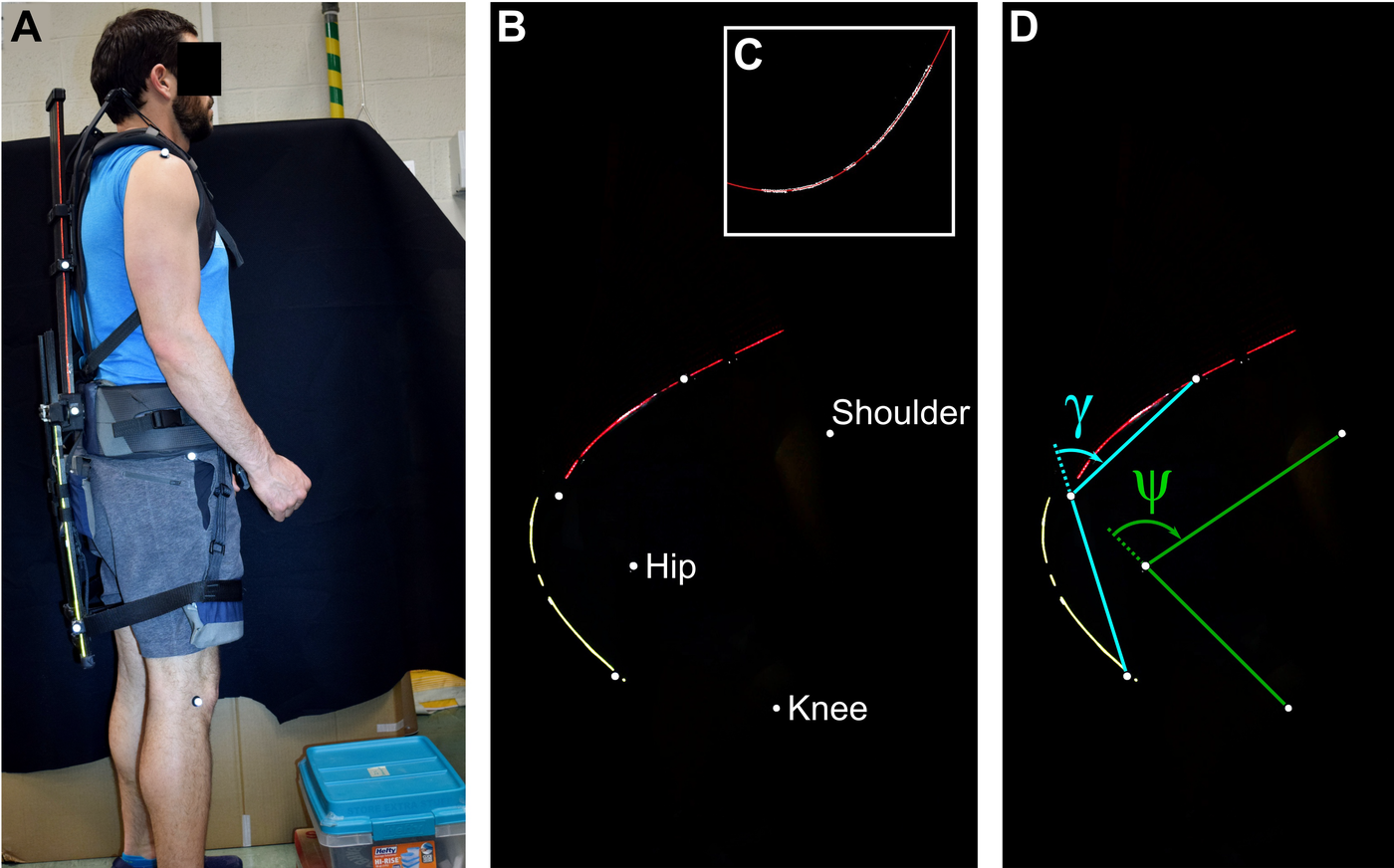
Figure 5b shows an example of an extracted image, with markers and beams visible. With each image, we measured two angles of interest, as well as the shape of the carbon fiber in the back and the legs. The carbon fiber shape was identified and extracted from the image with image processing techniques (Figure 5b). A quadratic polynomial was used to fit the carbon fiber shape of the back beam, and a cubic polynomial was used to approximate the carbon fiber shape of the leg beam. These polynomial orders were used because the back beam can be modeled as a cantilevered beam, clamped at the waist and with a force at the end. The leg beams were clamped at the waist, had a distributed force pushing outward from the posterior support cushions, and had an inward force at the leg slider. For both the back and leg beams, the image was rotated prior to curve-fitting so the point of maximum curvature was approximately at the bottom. An example of the rotated leg beam with the cubic fit is shown in Figure 5c.
Two angles were also measured as shown in Figure 5d. The “carbon fiber angle” or “CF angle” $ \gamma $
is measured between the markers on the exoskeleton. This gives a rough measure of how much the exoskeleton itself bent. When the person is standing vertically and the exoskeleton is not flexed at all, this angle is approximately −5° due to the marker at the leg slider sticking out further than the markers on the back and hip assembly. The second angle measured,
$ \gamma $
is measured between the markers on the exoskeleton. This gives a rough measure of how much the exoskeleton itself bent. When the person is standing vertically and the exoskeleton is not flexed at all, this angle is approximately −5° due to the marker at the leg slider sticking out further than the markers on the back and hip assembly. The second angle measured, $ \psi $
, is the angle between the participant’s shoulder, hip, and knee. This is referred to as the “hip angle” although it includes the pelvis and back’s curvature.
$ \psi $
, is the angle between the participant’s shoulder, hip, and knee. This is referred to as the “hip angle” although it includes the pelvis and back’s curvature.
Each carbon fiber shape was used to numerically calculate the energetic return using Equations 8–11.
 $$ U=\frac{1}{2}{\int}_0^L\frac{M^2}{EI} ds, $$
 $$ \mathrm{where}\hskip1em M(s)= EI\kappa $$
 $$ \kappa =\frac{d}{dx}{\theta}_{beam}, $$
 $$ {\theta}_{beam}={\tan}^{-1}\left(\frac{\Delta y}{\Delta x}\right). $$
In these equations, $ U $
is the strain energy in the beam due to bending,
$ U $
is the strain energy in the beam due to bending, $ E $
is the Young’s modulus,
$ E $
is the Young’s modulus, $ I $
is the moment of inertia,
$ I $
is the moment of inertia, $ s $
is the distance along the beam,
$ s $
is the distance along the beam, $ M $
is the bending moment in the beam,
$ M $
is the bending moment in the beam, $ \kappa $
is the curvature of the beam (the inverse of the radius of curvature),
$ \kappa $
is the curvature of the beam (the inverse of the radius of curvature), $ {\theta}_{beam} $
is the slope of a small segment of the beam, and
$ {\theta}_{beam} $
is the slope of a small segment of the beam, and $ x $
and
$ x $
and $ y $
are the coordinates of the beam polynomial curve fit in the extracted image.
$ y $
are the coordinates of the beam polynomial curve fit in the extracted image.
All angles and energy measurements were smoothed with a second-order low-pass filter with a cutoff frequency of 3 Hz. The torque $ \tau $
created by the exoskeleton was calculated by taking the derivative of the stored energy with respect to the carbon fiber angle
$ \tau $
created by the exoskeleton was calculated by taking the derivative of the stored energy with respect to the carbon fiber angle $ \gamma $
 $$ \tau =\frac{dU}{d\gamma }=\frac{dU}{dt}/\frac{d\gamma }{dt}. $$
Finally, the hysteresis of the exoskeleton was computed by integrating the torque during the lowering and raising portions of the lifting cycle, then subtracting their ratio from 1.
Results and Discussion
Exoskeleton Energetic Analysis
The results of the experimental analysis are shown in Table 3 and Figure 6. Figure 6f shows the total energy stored in the carbon fiber at the deepest portion of the lift, divided into the contributions from the back and leg beams. Interestingly, the leg carbon fiber serves as the main location of energy storage with an average stored energy of 52–62 J depending on the lift type, corresponding to 0.87–0.95 J/beam. This is around twice as much as the energy stored in the back beams (15–24 J, corresponding to 0.35–0.57 J/beam), despite the legs together having 2/3 of the number of carbon fiber beams as does the back. The higher energy in the leg beams is likely to the much smaller radius of curvature enforced with the leg beams, which bend sharply around the wearer’s hip and posterior.
Summary of results from human subjects experiments

Note: Numbers shown are the mean ± standard deviation.
(a) Stored energy in the exoskeleton as a function of carbon fiber angle $ \gamma $
, plotted for all participants. A cubic fit to the freestyle data is also shown for reference, which has equation
$ \gamma $
, plotted for all participants. A cubic fit to the freestyle data is also shown for reference, which has equation $ U=-0.0000787{\gamma}^3+0.0160{\gamma}^2+0.229\gamma +0.918 $
. (b) Comparison between the hip angle
$ U=-0.0000787{\gamma}^3+0.0160{\gamma}^2+0.229\gamma +0.918 $
. (b) Comparison between the hip angle $ \psi $
and the carbon fiber angle
$ \psi $
and the carbon fiber angle $ \gamma $
for all participants. (c) Torque
$ \gamma $
for all participants. (c) Torque $ \tau $
plotted versus carbon fiber angle
$ \tau $
plotted versus carbon fiber angle $ \gamma $
, along with the derivative of the fit line from (a). (d) Torque
$ \gamma $
, along with the derivative of the fit line from (a). (d) Torque $ \tau $
plotted versus hip angle
$ \tau $
plotted versus hip angle $ \psi $
. (e) Maximum moment
$ \psi $
. (e) Maximum moment $ M $
(Equation 9) along the leg beam, plotted versus carbon fiber angle
$ M $
(Equation 9) along the leg beam, plotted versus carbon fiber angle $ \gamma $
. (f) Graph of the contributions to the stored energy from the back and leg. The total stored energy for each participant is also plotted. One subject’s squat energy could not be determined.
$ \gamma $
. (f) Graph of the contributions to the stored energy from the back and leg. The total stored energy for each participant is also plotted. One subject’s squat energy could not be determined.
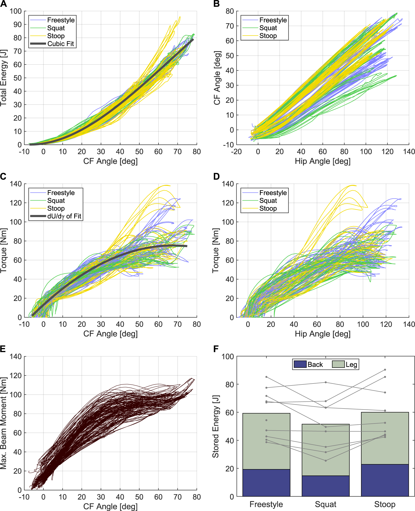
The total stored energy ranged from 25 to 90 J across all lift types and subjects. Although it had a wide range, the total energy varied consistently with the carbon fiber angle $ \gamma $
(Figure 6a), with nearly all of the data following the same cubic curve independent of the lift type. The relationship between the hip angle
$ \gamma $
(Figure 6a), with nearly all of the data following the same cubic curve independent of the lift type. The relationship between the hip angle $ \psi $
and carbon fiber angle
$ \psi $
and carbon fiber angle $ \gamma $
is shown in Figure 6b. There, it can be seen that the ratio between the hip angle and carbon fiber angle was nearly linear, but that this varied widely between participants. Thus, even though the maximum hip angles were relatively similar for all participants, the exoskeleton stored different amounts of energy due to the variable coupling between the exoskeleton and the body between participants.
$ \gamma $
is shown in Figure 6b. There, it can be seen that the ratio between the hip angle and carbon fiber angle was nearly linear, but that this varied widely between participants. Thus, even though the maximum hip angles were relatively similar for all participants, the exoskeleton stored different amounts of energy due to the variable coupling between the exoskeleton and the body between participants.
The differences in coupling were due primarily to two factors: first, the exoskeleton straps could be tightened differently, and on some people, they were slightly tighter, which usually led to the exoskeleton following the body better. Second, we observed that on some individuals the leg pads slipped up more than on others. The leg pads tended to slip if the exoskeleton wearer had slippery clothing; the insides of the leg pads were made of a shiny spandex material, which had a low coefficient of friction. A different material might reduce this. Also, we observed that the exoskeleton tended to slip more on individuals who had legs that were more cylindrical, as compared to more conical. The cubic relationship between the stored energy and carbon fiber angle meant that small differences in carbon fiber angle corresponded to large differences in stored energy.
The exoskeleton returned around 95% of the stored energy, which is only slightly less than the energy returned by carbon fiber itself (98.3% at $ 0.5{S}_y $
). This indicates that any other losses in the exoskeleton structure (e.g., sliding between the beams) were small.
$ 0.5{S}_y $
). This indicates that any other losses in the exoskeleton structure (e.g., sliding between the beams) were small.
Kinematic Analysis
The maximum hip angle was $ {119.1}^{\circ } $
for freestyle lifting,
$ {119.1}^{\circ } $
for freestyle lifting, $ {115.9}^{\circ } $
for squat lifting, and
$ {115.9}^{\circ } $
for squat lifting, and $ {109.5}^{\circ } $
for stoop lifting. Despite squat lifting having an average hip angle in between that of the other two lift types, it had the smallest average CF angle of
$ {109.5}^{\circ } $
for stoop lifting. Despite squat lifting having an average hip angle in between that of the other two lift types, it had the smallest average CF angle of $ {54.5}^{\circ } $
, as compared to
$ {54.5}^{\circ } $
, as compared to $ {61.8}^{\circ } $
for freestyle and
$ {61.8}^{\circ } $
for freestyle and $ {60.4}^{\circ } $
for stoop. This difference was because the leg pads on the exoskeleton tended to slip more during the squat posture, as the back was straighter and the hip bent to a sharper angle. Also due to the straighter back, in squat lifting the back carbon fiber beams stored a smaller percentage of the total energy (28%) as compared to the other lifting styles, while in stoop the back beams had the highest percent contribution to the stored energy (39%) due to the increased curvature of the back. As expected, the torso inclination was greatest for stoop lifting, followed by the freestyle and squat styles (Table 3 and Figure 1).
$ {60.4}^{\circ } $
for stoop. This difference was because the leg pads on the exoskeleton tended to slip more during the squat posture, as the back was straighter and the hip bent to a sharper angle. Also due to the straighter back, in squat lifting the back carbon fiber beams stored a smaller percentage of the total energy (28%) as compared to the other lifting styles, while in stoop the back beams had the highest percent contribution to the stored energy (39%) due to the increased curvature of the back. As expected, the torso inclination was greatest for stoop lifting, followed by the freestyle and squat styles (Table 3 and Figure 1).
Exoskeleton Torque
The exoskeleton torque is plotted in Figure 6c versus carbon fiber angle, along with the derivative of the cubic fit line from Figure 6a. The torque is also plotted in Figure 6d versus hip angle. As can be seen, the torque is relatively consistent across people and lifting styles, and roughly follows a sinusoidal shape, which is desired.
The peak torque was 70–72 Nm depending on the lifting style. This is approximately 42% of the 171 Nm needed to statically support the torso of a 50th percentile male during freestyle lifting (Figure 1). For comparison, the exoskeleton reduced the iliocostalis erector spinae and longissimus erector spinae during lifting by 29–32% on average (Alemi et al., Reference Alemi, Geissinger, Simon, Chang and Asbeck2019). During a lift the back muscles must support not only the static torque of the torso’s mass but also torques from accelerating and decelerating its inertia; the total torque including both of these effects can be 123–200% of the static torque depending on the lift speed (Lindbeck and Arborelius, Reference Lindbeck and Arborelius1991). Thus, since the back muscles must support the inertial torques as well as the static torques during a lift, it is reasonable to expect that the percentage reduction in back muscle activity while wearing the exoskeleton (29–32%) would be smaller than the percentage of the static torque compensated by the exoskeleton (42%). The existence of inertial torques also implies that a passive back exoskeleton that perfectly compensates for static torso torques could only reduce back muscle activity by 50–82%; an active back exoskeleton that also compensates for inertial torques could theoretically reduce the back muscle activity by a larger amount.
Similarly, with a maximum of 90 J and an average of around 60 J of energetic return, the exoskeleton provides less than our target value of 100 J. The differences between the target values and our results for both the torque and energy are likely due to the method of selecting the exoskeleton’s strength: the number of carbon fiber beams was selected based on comfort during initial user testing. It is likely that the individuals who provided initial feedback were not fully adapted to the exoskeleton, and could have preferred additional force once they gained more experience with the exoskeleton. Also, the peak torque is relatively close to that required for a 5th percentile female doing a squat lift (76 Nm).
The maximum beam moment $ M $
(Equation 9) along the leg beams multiplied by the number of leg beams is shown in Figure 6e. This follows a similar shape as the torque, with slightly higher values. The maximum of all subjects and lifts was 117 Nm, which corresponds to a maximum moment of
$ M $
(Equation 9) along the leg beams multiplied by the number of leg beams is shown in Figure 6e. This follows a similar shape as the torque, with slightly higher values. The maximum of all subjects and lifts was 117 Nm, which corresponds to a maximum moment of $ {M}_{beam}=4.18\hskip0.5em \mathrm{N}\mathrm{m} $
per beam. The stress due to bending of
$ {M}_{beam}=4.18\hskip0.5em \mathrm{N}\mathrm{m} $
per beam. The stress due to bending of $ \sigma = Mc/I $
, where
$ \sigma = Mc/I $
, where $ c $
is half of the beam thickness, is 697 MPa or
$ c $
is half of the beam thickness, is 697 MPa or $ 0.41{S}_y $
. Thus, the carbon fiber should have a cycle life of
$ 0.41{S}_y $
. Thus, the carbon fiber should have a cycle life of $ >{10}^6 $
during normal operation per Table 2.
$ >{10}^6 $
during normal operation per Table 2.
Slider Movement
The torso slider moved a mean of 7.9 cm during squat lifting, 9.1 cm during freestyle lifting, and 12.2 cm during stoop lifting, while the leg slider moved a mean of 3.0, 3.2, and 4.0 cm, respectively. In all cases, the sliders moved closer to the ends of the beams. Besides accommodating the kinematic differences between the wearer and exoskeleton, this motion also contributed to the torque curve flattening at the deepest parts of the bend, as the moment arms became longer. For both the torso and legs, the amount of slider motion was not correlated with the subject’s height or weight. It may be that the variation in slider motion amounts is more related to the participants’ specific lifting techniques rather than variation in body type.
If we compare the conditions for a given participant, sliding behavior is more predictable. On average, the torso slider moved nearly three times as much as the leg sliders. This is likely because the leg sliders were frequently close to the end of their travel range, while the back assembly could move upward quite a bit for most users. When the leg sliders reached the end of their travel range, the leg pads sometimes moved upward on the thighs to help accommodate the kinematic difference between the exoskeleton and body.
The question remains open as to whether sliding is necessary. The webbing straps coupling the exoskeleton to the wearer and the other soft interfaces could potentially account for the kinematic differences between the exoskeleton and wearer. In this case, the sliders could be affixed to the carbon fiber beams at the middle of their travel range for each user. However, this would cause the forces on the user’s torso to be not perfectly perpendicular to their body. For the legs, placing the sliders at the middle of their travel range would correspond to affixing the sliders as low as possible to the carbon fiber beams. With the leg pads held up by the straps in the front of the body, the straps would initially be angled downward away from the body. At large hip angles, this would make the forces on the user to be more perpendicular to the body, potentially preventing the thigh pads from sliding upward on the wearer’s legs.
Conclusion
In this paper, we calculate the torques needed to support the torso at different angles, and compare different possible methods of energy storage including the material weight and volume, hysteresis, and cycle lifetime. Much of this analysis is also applicable to passive exoskeletons for other parts of the body. While carbon fiber presents many benefits and thus was used in our design, several other materials are good choices as well. The best spring material for an exoskeleton will also depend on other factors such as the exoskeleton’s form factor or the ease of manufacturing, and indeed a variety of materials have been used by different groups.
We also presented a new exoskeleton with carbon fiber beams as the sole elastic mechanism. The carbon fiber provides large amounts of torque, with an average of 70–72 Nm as set up for this experiment. We note that while this torque is greater than other exoskeletons in the literature (PLAD: 36 Nm (Abdoli-Eramaki et al., Reference Abdoli-Eramaki, Stevenson, Reid and Bryant2007); Laevo: 23 Nm (Koopman et al., Reference Koopman, Kingma, Faber, de Looze and van Dieën2019a); SPEXOR: 50 Nm (Baltrusch et al., Reference Baltrusch, van Dieen, Koopman, Naf, Rodriguez-Guerrero, Babič and Houdijk2020); Biomechanically-Assistive Garment: 33 Nm (Lamers et al., Reference Lamers, Yang and Zelik2017), it is still less than half of the torque needed to statically support the torso of a 50th percentile male, and it only reduced the back muscle activity by 29–32% (Alemi et al., Reference Alemi, Geissinger, Simon, Chang and Asbeck2019). Future exoskeletons may be able to create larger muscle reductions with larger torques. We also note that it remains to be seen what exoskeleton torque is best for optimizing comfort and mobility while maximally reducing the risk of injury.
In our exoskeleton, the torque was a reliable function of the overall carbon fiber angle, but varied widely from person to person due to the coupling between the carbon fiber and body. The exoskeleton’s structure and soft goods have the benefit of making the exoskeleton easily adjustable (by tightening or loosening the straps), but they also lead to inconsistency in the torque applied to the body. The exoskeleton also allows the thigh cuffs to sometimes slide along the legs of the wearer, thereby reducing the torque provided. Future research should investigate other structures which may solve this problem, for example, by removing the sliders.
The exoskeleton presented here applies a significant restoring moment to the body. This indicates that the lumbar spinal compression is decreased, which in turn likely reduces the risk of injury (Dolan and Adams, Reference Dolan and Adams1998; Granata and Marras, Reference Granata and Marras1999; Lamers et al., Reference Lamers, Yang and Zelik2017). Additional investigation into the biomechanical effects of the exoskeleton on the wearer is necessary. Beyond that, additional studies are needed to determine the long-term effects of wearing an assistive device for the back, and the factors leading to adoption rates for exoskeleton wear.
Acknowledgments
We are grateful for the following individuals who contributed to the early development of the exoskeleton: David Weissbrodt, Bonham Ekleberry, Chris Loll, and Maria-Fe Thielman.
Funding Statement
This research was funded by Lowe’s, Inc. and the National Science Foundation (Grant number 1718801).
Competing Interests
S.E.C., T.P., J.G., and A.T.A. are co-authors on a patent for the exoskeleton.
Authorship Contributions
S.E.C., T.P., T.R.P., J.H., J.G., and A.T.A. designed the exoskeleton; T.P. and T.R.P. completed the final detailed mechanical design. S.E.C. and J.H. collected materials data. S.E.C. and A.T.A. performed the materials analysis and the beam image processing. T.P. and A.T.A. derived the slider analysis. M.A. contributed to the early analysis of the exoskeleton. A.A.S. and T.R.P. made the human subjects test setup, and A.A.S. performed testing. S.E.C. and A.T.A. wrote the manuscript.
Data Availability Statement
The data that support the findings of this study are available on reasonable request from the corresponding author, A.T.A. The data are not publicly available due to institutional review board restrictions.
Ethical Standards
The authors assert that all procedures contributing to this work comply with the ethical standards of the relevant national and institutional committees on human experimentation and with the Helsinki Declaration of 1975, as revised in 2008.
Appendix A: Material comparison
Suppliers and details for the elastic mechanisms in Figure 2
Abbreviations: NGR, natural gum rubber.No., number.
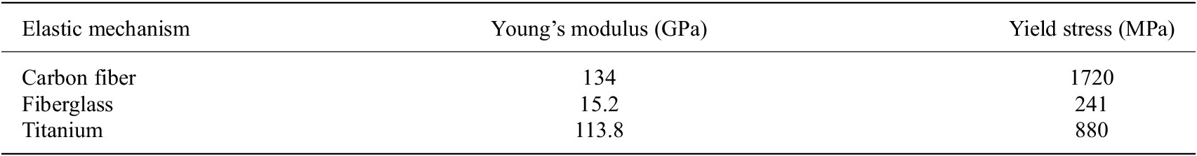
The carbon fiber, fiberglass, and titanium had the following material properties.
Material properties for the carbon fiber, fiberglass, and titanium
In Figure 2, the Cantilever loading cases were computed by $ U=\left({F}^2\hskip0.1em {L}^3\right)/\left(6\hskip0.1em E\hskip0.1em I\right) $
, where
$ U=\left({F}^2\hskip0.1em {L}^3\right)/\left(6\hskip0.1em E\hskip0.1em I\right) $
, where $ U $
is the energy,
$ U $
is the energy, $ F $
is the applied load at the end of the beam,
$ F $
is the applied load at the end of the beam, $ L $
is the beam length,
$ L $
is the beam length, $ E $
is the Young’s modulus, and
$ E $
is the Young’s modulus, and $ I $
is the area moment of inertia which is
$ I $
is the area moment of inertia which is $ I=b\hskip0.1em {h}^3/12 $
for a rectangular beam. Note that we are ignoring the strain energy from the shear, which is typically very small. The Moment loading cases were computed by
$ I=b\hskip0.1em {h}^3/12 $
for a rectangular beam. Note that we are ignoring the strain energy from the shear, which is typically very small. The Moment loading cases were computed by $ U=\left({M}^2\hskip0.1em L\right)/\left(2\hskip0.1em E\hskip0.1em I\right) $
, where
$ U=\left({M}^2\hskip0.1em L\right)/\left(2\hskip0.1em E\hskip0.1em I\right) $
, where $ M $
is the applied end moment and the other terms are the same as in the Cantilever loading equation.
$ M $
is the applied end moment and the other terms are the same as in the Cantilever loading equation.
To perform the calculations for NGR, samples of NGR were first measured in an Instron machine at 50 and 100% elongation (see Appendix B for details). The stiffness $ k $
was extracted from the measured data using the ratio of force to displacement at the most-stretched point, and then an estimate using Hooke’s law (
$ k $
was extracted from the measured data using the ratio of force to displacement at the most-stretched point, and then an estimate using Hooke’s law ( $ F= kx $
) was calculated. Estimates for 200 and 300% were done using the stiffness from 100% elongation. Energy for the calculated NGR was done with
$ F= kx $
) was calculated. Estimates for 200 and 300% were done using the stiffness from 100% elongation. Energy for the calculated NGR was done with $ U=1/2\hskip0.1em k\hskip0.1em {x}^2 $
.
$ U=1/2\hskip0.1em k\hskip0.1em {x}^2 $
.
For the gas springs, if the initial force $ {F}_1 $
, maximum force
$ {F}_1 $
, maximum force $ {F}_2 $
(which occurs at 90% of the stroke length), and stroke length
$ {F}_2 $
(which occurs at 90% of the stroke length), and stroke length $ {L}_{stroke} $
were available, then the initial length of the chamber holding the gas was calculated as
$ {L}_{stroke} $
were available, then the initial length of the chamber holding the gas was calculated as $ {L}_1={F}_2\hskip0.1em \left(0.9{L}_{stroke}\right)/\left({F}_2-{F}_1\right) $
. Then, for an arbitrary displacement
$ {L}_1={F}_2\hskip0.1em \left(0.9{L}_{stroke}\right)/\left({F}_2-{F}_1\right) $
. Then, for an arbitrary displacement $ x $
of the gas spring piston, the force is
$ x $
of the gas spring piston, the force is $ F={F}_1\hskip0.1em {L}_1/\left({L}_1-x\right) $
. This was numerically integrated to find the stored energy. If only the initial force was available, the energy was computed by
$ F={F}_1\hskip0.1em {L}_1/\left({L}_1-x\right) $
. This was numerically integrated to find the stored energy. If only the initial force was available, the energy was computed by $ U={F}_1\hskip0.1em {L}_{stroke} $
.
$ U={F}_1\hskip0.1em {L}_{stroke} $
.
Appendix B: Energy Storage and Hysteresis Testing
Table A3 provides details on the testing done to measure the energy storage and hysteresis values of various materials. The same test results were used for both energy storage and hystersis measurements. The materials tested were the same as those listed in Appendix A.
Test conditions for the materials in Figure 2 and Table 1: In the Type column, “Ext” indicates extension, “Comp” indicates compression testing, and “Bend” indicates three-point bend testing
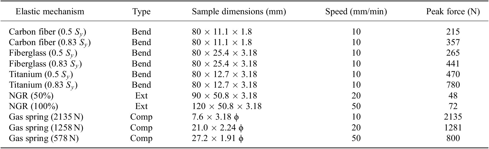
Notes: In the Sample Dimensions column, the dimensions are listed in the order of length × width × thickness, except for gas springs which show the extended length and the diameter of the cylinder body (ϕ). For the three-point bend testing, the sample length listed was the distance between end supports.
Abbreviation: NGR, natural gum rubber.
In detail, all measurements were conducted on an Instron 4204 machine (Instron, Norwood, MA). The sample was secured in the machine, and cycled five times from a small preload ( $ <1 $
N) up to the force specified in the table. The carbon fiber, fiberglass, and titanium were each tested to 50 and 83% of their yield strength. Each sample was tested three times. The hysteresis from the fifth cycle was found, and the results from the three tests averaged together to generate the final hysteresis value.
$ <1 $
N) up to the force specified in the table. The carbon fiber, fiberglass, and titanium were each tested to 50 and 83% of their yield strength. Each sample was tested three times. The hysteresis from the fifth cycle was found, and the results from the three tests averaged together to generate the final hysteresis value.
Several types of testing were performed, corresponding to how the energy storage element could be used in practice. For the carbon fiber, fiberglass, and titanium, three-point bending was conducted. For the NGR, the two ends of a sample were clamped in the machine, then two levels of elongation, 50 and 100 $ \% $
were tested. The gas springs were secured into the machine with clamps and a small fixture, then compressed 90% of their travel.
$ \% $
were tested. The gas springs were secured into the machine with clamps and a small fixture, then compressed 90% of their travel.


 Open access