


1. Introduction
Additive Manufacturing (AM) has evolved from a pure rapid prototyping technology into a mature production technology for functional components. Among AM processes, Material Extrusion (MEX), also known as Fused Deposition Modelling (FDM), offers advantages in terms of cost efficiency, material diversity, and broad industrial accessibility. Nevertheless, polymer-based components produced by MEX remain limited by dimensional inaccuracies, anisotropic behaviour, and insufficient surface quality.
Typically, MEX components are part of an assembly, where they must be joined in accordance with defined mechanical and functional requirements. In many cases rolling element bearings are used as connecting elements between individual components to enable the rotational function. However, when integrating rolling bearings – a machine element proven millions of times in practice – the specific requirements of the bearing often conflict with MEX-specific limitations such as limited dimensional accuracy of cylindric features, anisotropic stiffness and insufficient surface quality for bearing seats. Consequently, the integration of rolling bearing, especially for high-demand applications, are highly desirable but still present many challenges.
Building on the authors’ previous work on integrating high-strength anchoring points for screw connections in MEX components, this paper presents a new approach that addresses MEX-specific limitations while providing a mechanically robust and geometrically controllable interface for standardized machine elements. The approach is based on the thermal application of threaded sleeves, which has been experimentally validated with respect to mechanical anchoring performance. In this contribution, the application of this process is extended conceptually towards the integration of rolling bearings, where the threaded sleeve is introduced as an interface element between the MEX component and the bearing. The rolling bearing integration is discussed as a target application and serves to outline the potential of the proposed method and directions for future experimental validation.
2. State of the art and technology
The integration of a conventional rolling bearing into a MEX component requires a two-sided consideration. Installation conditions for conventional rolling bearings are strictly defined by extensive guidelines, standards and manufacturer specifications. Section 2.1 provides an overview of these requirements. Section 2.2 illustrates how the integration of metallic rolling bearings is currently implemented according to the state of the art. Section 2.3 summarizes the findings from the current state of the art and research and derives the research gap, highlighting the lack of a systematic methodology for integrating conventional rolling bearings into MEX-manufactured components while ensuring compliance with functional, mechanical, and geometric requirements.
2.1. Integration of rolling element bearings in structural components
The state-of-the-art-way to integrate rolling element bearings into structural components, mostly casted or welded housings, is still to use a transitional fit with a slight tendency towards a shrink fit, e.g. defined by component tolerances of bore H7 in combination with an appropriate outer ring tolerance according to ISO 286 (Reference Niemann, Winter, Höhn and StahlNiemann et al., 2019). This standard solution generally assumes a standard steel alloy for the housing, the bearing outer race being typically manufactured out of the bearing steel quality alloy 100Cr6. In automotive light weight housing structures with aluminium housings, (Reference KirchnerKirchner, 2007), different bore tolerance is defined to alleviate the effect of different thermal expansion properties of aluminium and steel to avoid a too loose fit in operation conditions which are typically in the range of 70°C to 90°C in vehicle applications regardless of the propulsion concept.
a) Section of a housing drawing with an integrated steel ring in a die cast housing raw part, b) bearing frame taking over the radial bearing forces in an automotive transmission (Left: Lecture Notes TU Darmstadt, right with friendly permission of Bott Fahrzeugtechnik)

While standardized fits are well established for metallic housings, their direct transfer to polymer-based MEX components is not straightforward due to significantly lower stiffness, time-dependent deformation, and different thermal expansion behaviour.
2.2. Integration of conventional rolling bearings in MEX-components
Currently there is no standardized procedure for the integration of conventional rolling bearings into components manufactured by Material Extrusion (MEX). Instead, “best-practice” approaches to embed the bearing as functionally as possible into the printed structure are used. Common to all existing methods is that a core hole for the bearing is first defined in the CAD model.
When the model is transferred to the slicing software for print preparation, the next important aspect is its orientation within the print chamber. Due to the distinct anisotropy of MEX-manufactured parts, orientation has a significant influence on the direction-dependent mechanical properties and must therefore be selected according to the expected load conditions (Reference Sandanamsamy, Harun, Ishak, Kadirgama, Samykano and TankSandanamsamy et al., 2025; Reference Lambiase, Pace, Andreucci and PaolettiLambiase et al., 2025; Reference Maydanshahi, Najari, Slatter and MohammadpourMaydanshahi et al., 2024).
Another important aspect during printing is the dimensional tolerance achievable for the printed component, particularly the core hole intended for bearing placement. Depending on printer precision and part orientation, these tolerances can vary significantly (Reference Fernández, Zapico, Blanco, Peña and FernándezFernández et al., 2025; Reference Abas, Awadh, Habib and NoorAbas et al., 2023). In addition, machine settings have a significant influence on the quality of the printed component (Reference Lambiase, Liparoti, Pace, Scipioni and PaolettiLambiase et al., 2024).
In practice, two main approaches are applied for integrating conventional bearings into MEX-manufactured components:
Pause-and-insert
By programming a pause command into the printer’s machine code after completion of the core hole, the bearing can be manually placed in the component. Printing can then be resumed and the outer bearing ring overprinted and thereby fixed in place. This procedure is also used in practice for the integration of nuts. (Mark3D The Markforged Experts, 2024)
Press-fit
In this approach, the bearing is inserted after the MEX component has been completely printed. The bearing is press-fitted into the prepared core hole, ensuring its mechanical fixation (Figure 2). The relationship between press-in force and undersize of the core hole was investigated (Reference Palic, Petrovic, Palic, Milenkovic, Pesic, Rackov, Miltenović and BanićPalic et al., 2025).
Integration of a conventional rolling bearing into a MEX-Component

There is also research into printing separate optimized bearing rings, which are then integrated into a component as a connecting element (Reference Retuerta Del Rey, De Lucas Salgado, González Hernández and Chacón TanarroRetuerta Del Rey et al., 2024). Research into how a MEX component with an integrated bearing can fail was conducted by (Reference Khosravani, Sadeghian, Ayatollahi and ReinickeKhosravani et al., 2023). High accuracy requirements may require machining post-processing. Investigations in this context were carried out by (Reference Mourya, Bhore and WandaleMourya et al., 2023).
Overall, these findings indicate the need for a controlled and mechanically robust interface concept rather than a complete replacement of existing bearing integration principles.
2.3. Research gap
Current research and existing solutions in this field demonstrate ongoing efforts to combine the proven reliability of conventional rolling bearings with the potential of Material Extrusion (MEX) technology in order to achieve an optimal product outcome. Nevertheless, several fundamental questions—particularly with regard to the challenges in additive manufacturing outlined in Sections 1 and 2 — remain insufficiently resolved.
Accordingly, there is still a need for systematic research in the following areas:
-
• Positional and dimensional accuracy of integrated rolling bearings
-
• Performance and behaviour of dynamically loaded rolling bearings within MEX components
-
• Development of standardized methodologies for the integration of rolling bearings into MEX-manufactured structures
-
• Qualification and verification of integrated bearing seats
-
• Methods for non-destructive or component-preserving bearing disassembly
-
• Design and performance of bearing seats fabricated using high-performance filaments (e.g. PEEK, ULTEM)
However, in the present contribution, these aspects are not addressed experimentally. Instead, they are used to motivate a novel, structured approach aimed at enhancing the reliability and geometric controllability of bearing interfaces in MEX components.
3. Process requirements for the integration of conventional rolling bearings into MEX-manufactured components
3.1. Innovative application technology for threaded sleeves
In recent years, a specialized process has been developed for joining MEX components—particularly for detachable screw connections—that is tailored to the specific properties of layered materials (Reference Fürst and GöhlichFürst & Göhlich, 2024). This process enables the reliable integration of threaded inserts with metric internal threads and coarse external threads with large flanks into the component structure. As a result, significantly higher pull-out forces for the screws can be achieved compared to previous solutions.
The distinctive feature of this process lies in the fact that the thread flanks are strongly heated before insertion. Due to the resulting intense softening of the filament in the core hole area, the threaded sleeve must be inserted into the MEX component by means of a controlled and coordinated feed and rotational movement, adapted to its thread geometry. For this process, an open-parameter test bench was developed, which is shown in Figure 3.
Test bench for threaded sleeve application

The threaded sleeve to be inserted is attached to the drive shaft. The sleeve is then lowered and passes through an induction coil at a predefined speed in order to heat it to the target temperature. Upon reaching the specimen, the test bench switches to the application process and controls the feed and rotational movement according to the thread pitch of the sleeve until the application is fully completed. After successful insertion and re-solidification of the filament, the direction of rotation is reversed, and the test bench is separated from the specimen.
Results and Advantages of the Process
The developed process is both: reliable and repeatable, allowing for the integration of highly durable anchoring points for screw connections in MEX components. Initial tests demonstrated that the achievable pull-out forces are significantly higher than those obtained with conventional methods, such as melt-in inserts. Moreover, the localized heat transfer during insertion promotes extensive solidification around the screw-in area, enabling targeted material savings. The partial re-softening of the filament also allows for the compensation of build defects, ensuring that the threaded insert can be precisely positioned and aligned independently of the printed core hole geometry and position.
Test specification and result

Figure 4 Long description
Panel A: One photo and one diagram. The photo shows two test samples, one gold-colored and one silver-colored. The diagram depicts a test setup with a test sample placed on supports and a force applied downward at a rate of 5 millimeters per second. Panel B: One diagram. The diagram shows a rectangular area with labels indicating an infill of 50 percent, a core hole, and a full printed wall line area. Panel C: One graph. The graph is a line chart with the x-axis labeled Displacement in millimeters and the y-axis labeled Pull Out Force in kilonewtons. Two lines are plotted, one red and one blue, representing the pull-out force versus displacement for the two different test samples. The red line reaches a higher peak force and displacement compared to the blue line.
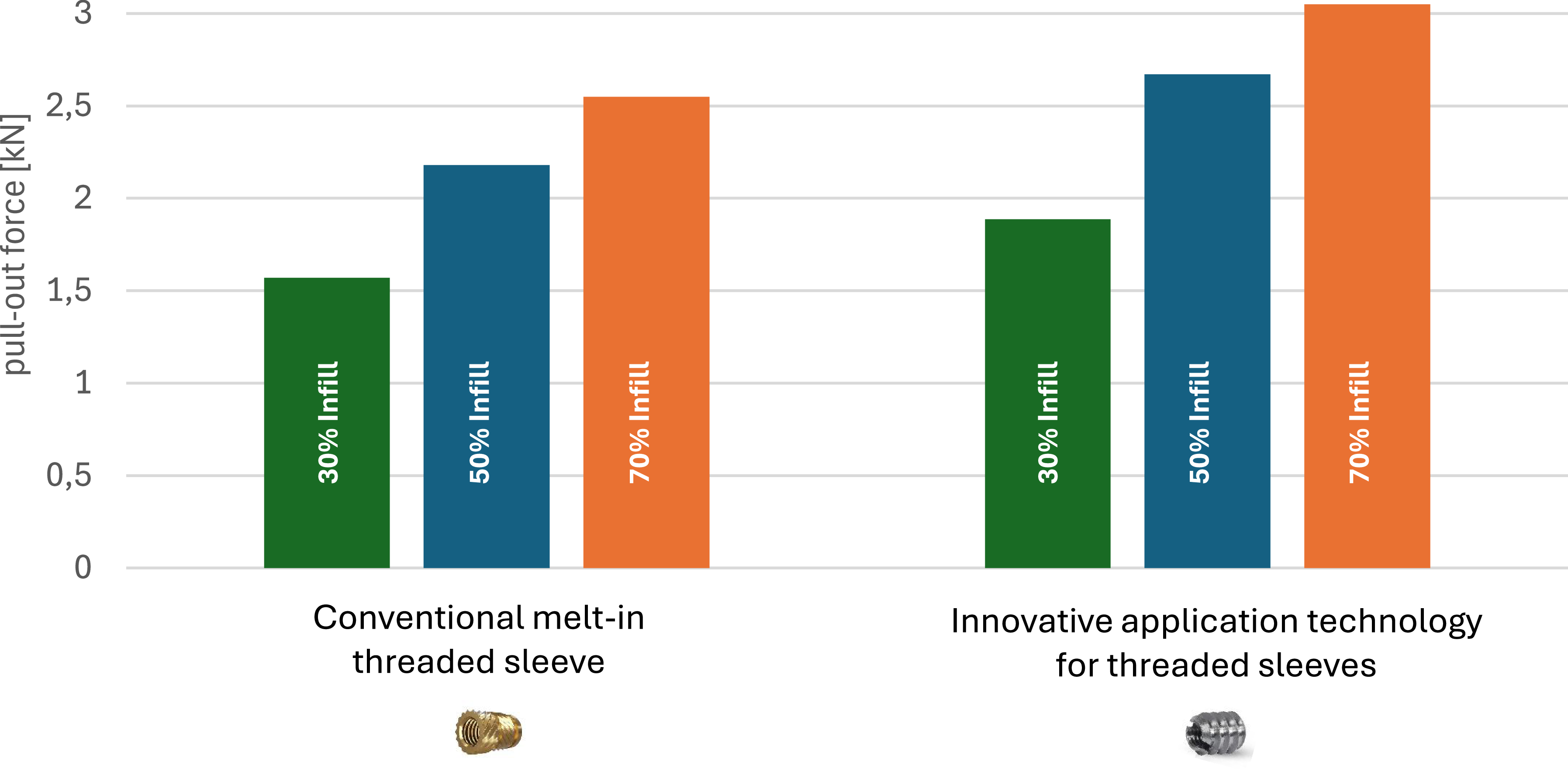
Figure 4 illustrates representative results of a pull-out test comparing conventional melt-in inserts with thermally applied threaded inserts. The data demonstrate not only a substantial increase in pull-out strength but also an enhanced structural stiffness of the component, which can be attributed to the localized introduction of thermal energy during the insertion process. Based on these results, further test series were conducted in which the infill was varied for both threaded sleeve variants and their application methods. The results for 30% and 70% infill, compared to 50% infill, can be seen in Figure 5.
Test results for infill variation

In all infill variants, the novel application process achieved more than 20% higher pull-out forces, compared to the conventional process. This indicates that the sleeve is deeply anchored in the component. This increased anchoring can be used to save material, as thinner or lighter components still provide the required stability. At the same time, the additional strength can be used to enhance functionality in component design, for example by integrating additional features or more complex geometries.
A more comprehensive description of the methodology and additional experimental results can be found in the corresponding research publication (Reference Fürst and GöhlichFürst & Göhlich, 2024). Although only a small number of samples were tested, the observed trends are consistent with and support the results reported in the previous publication. The European patent for this process was granted in July 2025 (Reference FürstFürst, 2025a).
3.2. Adapting the process to sleeves for mounting roller bearings
The approach pursued in this study aims to transfer the proven advantages of threaded insert applications (see Section 3.1) to the machine element conventional rolling bearing. On this basis a precisely positionable and high-strength bearing seat can be created, firmly anchored within the MEX component. The threaded insert serves as a suitable interface between the rolling bearing and the MEX component.
Figure 2 schematically illustrates the conventional integration of a standard rolling bearing into a MEX component. It becomes evident that the contact surface between the bearing and the component does not form an ideal interface. In particular, the standard requirements and guidelines for bearing integration (see Section 2.1) cannot be met.
The approach presented herein enables both, the MEX component and the bearing, to achieve improved conditions for a functionally and technically appropriate integration. On the side of the MEX component, a solid bond with the threaded sleeve is formed through localized remelting and subsequent solidification of the material. Manufacturing inaccuracies are compensated, while at the same time the sleeve can be precisely aligned during the application process.
The inner surface of the threaded sleeve can be tailored to meet the stringent requirements of, for example, the bearing manufacturer or relevant standards and guidelines, particularly with regard to tolerances and surface roughness.
Novel process for the integration of a conventional rolling bearing

Figure 6 Long description
A diagram illustrating the process of integrating a conventional rolling bearing into a component using a threaded sleeve. Panel 1: A pre-heated threaded sleeve is shown being applied to a MEX component. The sleeve has a diameter labeled as D CH, and the component has diameters labeled as D OC and D IC. Panel 2: The threaded sleeve is applied, and a re-melted filament is visible in the core hole area. Panel 3: A conventional bearing is shown being integrated into the component with a force labeled as F PI. Panel 4: The re-solidified filament in the core hole area after cooling is depicted, showing the final structure with the integrated bearing.
Figure 6 schematically illustrates the manufacturing process for integrating a rolling bearing according to the novel developed method in four steps. First, the designated core hole must be adapted to match the outer cylindrical diameter (
 $${D_{OC}}$$
) of the threaded sleeve. Following the procedure described in Section 3.1, the sleeve is preheated to a filament-specific temperature and inserted into the core hole by means of a controlled feed and rotational movement (
$${D_{OC}}$$
) of the threaded sleeve. Following the procedure described in Section 3.1, the sleeve is preheated to a filament-specific temperature and inserted into the core hole by means of a controlled feed and rotational movement (
 $${v_{FR}}$$
and
$${v_{FR}}$$
and
 $${v_{RR}}$$
, see Figure 6 (1)). The connection between the sleeve and the drive shaft can, for example, be achieved using an expandable mandrel, which simultaneously ensures proper centering of the sleeve.
$${v_{RR}}$$
, see Figure 6 (1)). The connection between the sleeve and the drive shaft can, for example, be achieved using an expandable mandrel, which simultaneously ensures proper centering of the sleeve.
After the sleeve has been applied and subsequently cooled, the bearing can be installed according to the specified requirements—for example, by press-fitting. For this purpose, the sleeve can be designed with a corresponding counter-bearing surface.
The corresponding patent application for the specific sleeves was published in November 2025 (Reference FürstFürst, 2025b).
At this stage, the approach is limited to a conceptual transfer of the validated threaded sleeve process, while experimental investigations on rolling bearing performance are subject to future work.
3.3. General design methodology for rolling element bearings
The main difference with regard to their application between threaded sleeves and rolling element bearings is most likely the higher requirements with regard to co-axiality and parallelism of neighbouring shafts and hence bearing seats. The handling of single sleeves needs to be evaluated, the main difficulty is expected in the area of highly loaded bearings, but analogies to the threaded sleeve can be utilized. The typical guidelines concerning manufacturing of bearings seats, their respective tolerances and the assembly of bearings and shaft, respectively, need to be expanded.
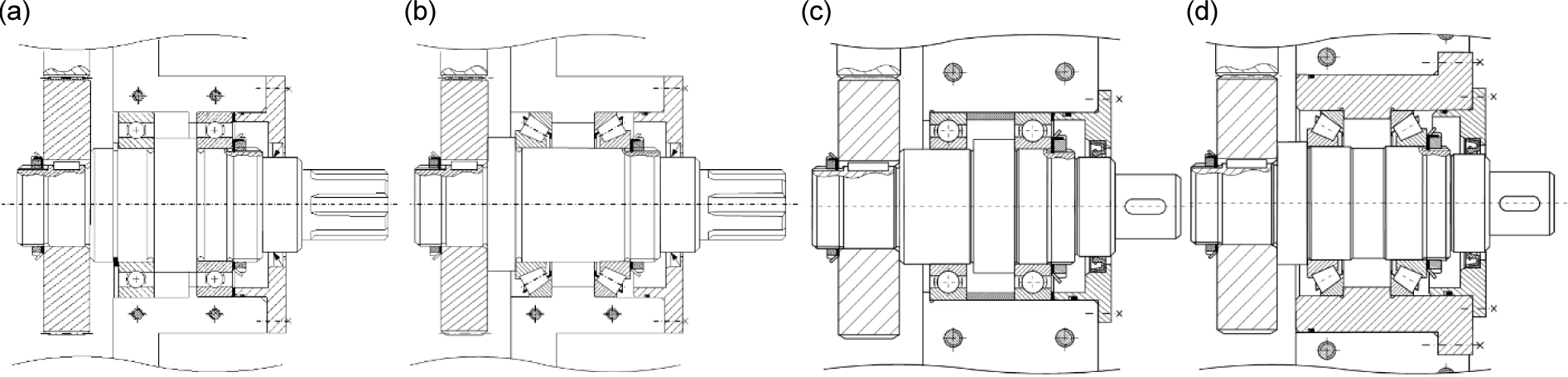
Design for assembly of rolling bearing arrangements: a) poor design requiring manufacturing of the bearing seats and assembly of rolling element bearings from two directions for a fix-loose-arrangement, b) for pre-tensioned O-Arrangement, c) improved bus still very heavy design in fix-loose-arrangement, d) improved design of a pre-assembly of the pre-tensioned bearing arrangement

The assembly process for the sleeves and their respective design needs to be drafted considering different bearing types and loading conditions. Finally, the system structure including e.g. parting planes of housing components needs to be considered. A major part of a methodology for the design of bearing arrangements in MEX-fabricated housing structures will cover the reliable and efficient evaluation of different design alternatives for a selection of the suitable design and manufacturing concept before embarking into embodiment design.
3.4. Outlook on bearing plate integration
In many applications, it will be necessary to combine sleeves for neighbouring bearing into a bearing plate to avoid the MEX fabricated being loaded with inappropriately high bearing forces. Not only the design and assembly process changes, it is also necessary to provide means to investigate the interference of stresses of neighbouring bearing seats, especially in the case of combined axial and radial loads. The dimensioning of the fixation of the bearing plate in the MEX fabricated structure will add additional complexity because of the loss of axial symmetry, that can be exploited for threaded sleeves as well as for single, ideally axially loaded rolling element bearings. No design guidelines were discovered for bearing arrangements in the context of additive manufacturing.
The process to assemble the bearing plate is to be analysed as well, a rotation as used in the predecessor-study is not applicable. The desired process will depart from the three ground rules of engineering design demanding simplicity, unambiguity and safety, (Reference Kirchner, Neudörfer, Bender and GerickeKirchner & Neudörfer, 2021), in order to achieve transferability of the concept.
4. Test bench and method for qualifying the bearing arrangement
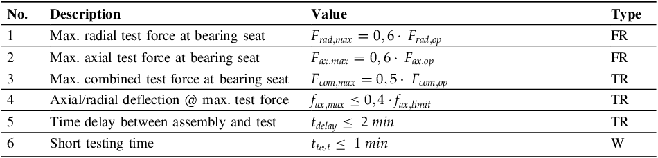
The failure of rolling element bearings and their surrounding support structure causes in the most practically relevant case the immediate failure of the drive system. Hence, the reliability of the bearing support in a MEX-fabricated housing needs to be proven. For the sake of ease of handing, the apparatus used to assemble the inductively heated bearing sleeve or bearing plate shall be used to also test the relevant stiffness parameter. In order to avoid permanent deformations of the housing structure or a static failure of the rolling element bearing itself, test forces need to be controlled. Some initial requirements for the testing method are listed in Table 1. (Reference KirchnerKirchner, 2020)
Proposal of requirements for the testing of the assembled bearing seat in a MEX-fabricated housing structure (TR=target requirement, FR=fixed requirement, W=wish)

The key idea is to keep the test forces well below the maximum operational forces and the resulting deflections small in order to avoid permanent damage. The limit values for the deflection in operation
 $${f_{ax,limit}}$$
and
$${f_{ax,limit}}$$
and
 $${f_{rad,limit}}$$
derive e.g. out of the limitations of a load carrying gear mesh in order to keep the contact pressure distribution within acceptable limits. The underlying assumption in the limitation of the measured deflections in test is a nonlinear progressive increase of the deflection with load being a characteristic behavior of highly loaded structure. A suitable testing method for cyclic loading conditions would require the set up of a dedicated bench with a shaker or pulsator in oder to subject the bearing seat in the MEX-housing to a representative number of loading events. For an initial test the static stress and deformation test is assumed to be of highest importance to prove the system reliability.
$${f_{rad,limit}}$$
derive e.g. out of the limitations of a load carrying gear mesh in order to keep the contact pressure distribution within acceptable limits. The underlying assumption in the limitation of the measured deflections in test is a nonlinear progressive increase of the deflection with load being a characteristic behavior of highly loaded structure. A suitable testing method for cyclic loading conditions would require the set up of a dedicated bench with a shaker or pulsator in oder to subject the bearing seat in the MEX-housing to a representative number of loading events. For an initial test the static stress and deformation test is assumed to be of highest importance to prove the system reliability.
Particular attention is required for the support of axial forces in the MEX-fabricated housing structure. For constant axial forces a lot of the considerations from the threaded sleeves can be transferred, for alternating axial forces the fatigue risk needs to be assessed for the housing. A separate axial fixation of the rolling element bearing will be most likely required in order to properly host the bearing in the housing using the sleeve shown in Figure 5.
5. Conclusion and outlook
This study demonstrates that the integration of conventional, well-established machine elements into additively manufactured components requires specific adaptations in order to exploit the potential of the resulting assemblies. In particular, meeting the often stringent functional, mechanical and geometric requirements of standardized machine elements poses a considerable challenge for MEX-components.
Building on the authors’ previous work, this paper introduces and discusses a novel approach for the integration of rolling bearings into MEX-components. The method addresses two central aspects: the demanding requirements of standardized metallic bearings and the process inherent characteristics of MEX components. By providing a mechanically robust and geometrically controllable interface concept, the approach outlines a potential pathway for extending the application range of MEX technology towards mechanically demanding use cases.
Moreover, the validated threaded sleeve application process enables the qualification of the created interface through process parameters, for example by monitoring the application torque. Conceptually, this interface principle may be transferable to other bearing types, such as journal bearings, as well as to further machine elements with high interface requirements.
However, the implementation of this concept for rolling bearings is currently limited to a conceptual level and requires further fundamental research. This includes the optimization of the application parameters, sleeve design, the design of the MEX component at the bearing interface, as well as comprehensive experimental validation under relevant load conditions. These aspects should be the focus of future work. In the long term, such an interface-based approach could contribute to the development of standardized design guidelines for integrating high-requirement machine elements into MEX-manufactured components.




 Open access

