


Introduction
Industrial robots play an indispensable role in modern manufacturing industries such as automobile manufacturing, aerospace, shipbuilding, and construction. They can automatically perform various tasks, including welding, assembly, spraying, etc., improving the efficiency of production lines, reducing labor costs, and ensuring product consistency and quality. Automation and precision make them an important tool for improving production efficiency and product quality (Moreira et al., Reference Moreira, Neto and Vidal2023; Borboni et al., Reference Borboni, Reddy and Elamvazuthi2023; Yamaguchi and Inaba, Reference Yamaguchi and Inaba2023). However, traditional industrial robots have limitations in certain complex tasks and harsh environments, especially in the field of spraying. The spraying process of traditional robots is often limited by the workspace, complex surface shape, material property changes, and environmental factors (Sotnik and Lyashenko, Reference Sotnik and Lyashenko2022; Chen et al., Reference Chen, Li and Ge2020; Li et al., Reference Li, Zhao and Zhao2019; Wu et al., Reference Wu2020; Kumar et al., Reference Kumar, Kalita and Chatterjee2022; Wang et al., Reference Wang2022). The following problems still exist when planning robot spraying operations:
-
• Insufficient spraying precision: Industrial robots have difficulty maintaining a uniform coating thickness and consistent coating quality during the spraying process, especially for workpieces with complex geometries. This lack of precision may lead to coating defects such as too thick or too thin a coating or uneven surfaces (Gabbar and Idrees, Reference Gabbar and Idrees2024; Santhosh et al., Reference Santhosh, Sut, Uma and Sethuramalingam2024; Tanaka et al., Reference Tanaka, Takahashi and Iwata2024; Wang et al., Reference Wang, Cao, Li, Wu, Li, Hu and Tian2023).
-
• Difficult path planning: Path planning and spray angle adjustment are very difficult for irregular or complex surfaces. Traditional methods have difficulty dynamically adapting to the complex curved surfaces of different workpieces, resulting in uneven spray coverage or blind areas (He et al., Reference He, Lu, Wen, Saunders, Yang, Schoonover, Wason, Julius and Wen2023; Chen et al., Reference Chen, Chen, Chen, Ding, Liu and Yan2024; Lewke et al., Reference Lewke, Wu, List, Gärtner, Klassen and Fay2024).
-
• Lack of real-time feedback and adjustment: During the spraying process, there is a lack of real-time feedback and adjustment capabilities, making it difficult to promptly correct problems that occur during the spraying process, such as missed spraying, overspraying, or spraying deviations (Padhiary et al., Reference Padhiary, Tikute, Saha, Barbhuiya and Sethi2024; Patel, Reference Patel2024; Wei et al., Reference Wei, Li, Tian, Wei, Zhang, Liao and Cao2024).
-
• Poor adaptability to complex workpieces: Existing spraying systems have poor adaptability when processing workpieces with complex geometric shapes and are prone to spraying dead angles and uneven spraying, which affects the quality of the final product (Tasnim et al., Reference Tasnim, Ahmed, Tasnim, Shidujaman and Ahmed2023; Luo and Qiao, Reference Luo and Qiao2023).
-
• Weak response to environmental changes: Changes in temperature, humidity, and airflow in industrial environments can affect the spraying effect, and existing systems often find it difficult to adjust spraying parameters in real time to cope with these changes (Liu et al., Reference Liu, Cheng, Su, Duan and Tan2024; Zeng et al., Reference Zeng, Zhang, Chien, Tju, Wiesse, Cao, Zhou, Li and Chen2024; Prezas et al., Reference Prezas, Arkouli, Michalos, Angelakis, Gkournelos and Makris2024).
In addition, there are obvious gaps in current research on robot spraying and spraying systems:
-
• Insufficient research on closed-loop control systems: Many existing spraying systems are still open-loop systems and lack closed-loop control mechanisms for real-time monitoring and feedback of the spraying process. The real-time detection and automatic adjustment of coating quality remain difficult points in research.
-
• Limited research on the application of digital twin technology: Although the application of digital twin technology in the manufacturing industry has begun to attract attention, relatively few studies have focused on its application in spraying processes, especially how to achieve close integration of highly simulated virtual environments and actual operations.
-
• Optimization of spraying paths for complex geometric workpieces: Most existing research focuses on spraying path planning for simple workpieces, and there is insufficient research on how to optimize spraying paths for workpieces with complex geometric shapes efficiently and accurately.
-
• Weak research on human–machine collaboration: The application of human–machine collaboration in the spraying process is still in the exploratory stage, especially in terms of how to effectively combine the flexibility of human operators with the high-precision operation of robots, and research is still insufficient.
-
• Integrated application of multisensor fusion technology: Multisensor fusion has potential in real-time monitoring of spray quality and workpiece status, but there is little research on its integrated application in actual industrial spraying, especially in how to use these data for real-time adjustments.
-
• Insufficient development of intelligent spraying systems: Intelligent spraying systems can automatically adjust spraying parameters according to the workpiece shape, material properties, environmental conditions, etc., but there is still a large gap in research in this field, especially in algorithm optimization and system integration.
At present, research on digital twin technology is mostly focused on the visualization of macro production data, such as digital twin modeling of factories, workshops, and production lines. Research on digital twin modeling of actual physical equipment is still relatively limited. ØVERNA in Norway uses visual components to build a visualization model and explores the synchronization of industrial robot operation in the information-physical space under the OPC UA protocol. Zhang Aimin et al. (Zhang et al., Reference Zhang, Kong and Wang2010) developed an industrial robot monitoring and diagnosis system based on the socket protocol, which can view a robot’s motion status in real time. GARG et al. (Garg et al., Reference Garg, Kuts and Anbarjafari2021) used a VR controller to control the trajectory of a FANUC industrial robot on the basis of digital twin and virtual reality technology and verified the accuracy of the trajectory. ELVIRA-ORTIZ et al. (Elvira-Ortiz et al., Reference Elvira-Ortiz, Romero-Troncoso and Jaen-Cuellar2016) collected and remotely monitored the torque, temperature and other signals of industrial robots, which can predict and promptly handle the faults of industrial robots. However, the current application of digital twin technology for industrial robots focuses mainly on simulating the operation process through virtual models and visual monitoring of actual working conditions (Cai et al., Reference Cai, Zhu and Shi2021; Du et al., Reference Du, Luo and Peng2023). Real-time interaction between virtual and real models has not been achieved, and efficient human–machine collaboration cannot be achieved.
Difficulties in the spraying process pose significant challenges in industrial production. First, spray path planning needs to consider the complex shape and size of the target surface to ensure complete coverage of the coating while avoiding overlap or omissions (Wu and Tang, Reference Wu and Tang2023). Solutions include the use of path planning algorithms combined with 3D scanning or workpiece models to plan the optimal path in a virtual environment and fine-tune the path in real time through a digital twin model. Second, uniform control of spray thickness is critical to coating quality (Gleeson et al., Reference Gleeson, Jakobsson and Salman2022). Different surface characteristics and angles may cause thickness variations, which require real-time monitoring and adjustment (Ren et al., Reference Ren, Sun and Hui2023). Real-time sensors are usually used to monitor the spray thickness and feed the data back to the virtual environment so that the operator can check and adjust it in real time in the virtual interface. In addition, environmental factors such as temperature and humidity have a direct effect on the spraying process, requiring real-time parameter adjustment to adapt to different conditions. Solutions include simulating the spraying process under different environmental conditions in a virtual environment and adjusting the parameters according to the guidance of the digital twin model. Finally, changes in material properties may lead to inconsistent coating qualities. By monitoring material properties in real time and feeding data back to the virtual environment, the operator can adjust the spraying parameters on the basis of real-time data to adapt to changes in material properties. In summary, as an advanced virtual simulation technology, digital twin technology provides a new solution to overcome the challenges faced by traditional industrial robots in spraying tasks (Chancharoen et al., Reference Chancharoen, Chaiprabha and Wuttisittikulkij2022). Through digital twin and human–machine collaboration, the difficulties in the spraying process can be better solved, the accuracy and efficiency can be improved, and high-quality spraying results can be ensured, thus achieving better application results in industrial manufacturing.
Therefore, this paper studies real-time guided spraying methods for industrial robots that are based on digital twin and human–machine collaboration. By building a human–machine collaborative spraying system based on digital twin technology, it aims to solve the accuracy and adaptability problems faced by industrial robots in the spraying of complex geometric workpieces. The research content includes the construction of a highly simulated digital twin model, initial calibration and real-time synchronization with the physical environment to achieve consistency between virtual and real environments; the design and implementation of a virtual reality-based operating system, in which the operator guides the spraying robot in real time through a VR device; and the acquisition and feedback of key data in the spraying process through multisensor fusion technology. The experiment analyzes the performance of the digital twin system in the spraying of complex workpieces, especially the optimization of spray path planning, the uniformity of the coating thickness, and the adaptability of the system in response to actual environmental changes.
Human–machine collaborative digital twin modeling
Digital twin and human–machine collaboration framework
Digital win have achieved important applications in the industrial field. In industrial robots, a digital twin can help achieve more accurate process control and performance prediction. In the real-time guided spraying process, digital twin technology acts as a bridge between the virtual environment and the real environment, thereby improving work efficiency and quality. The digital twin model architecture of Tao et al. (Reference Tao, Liu and Zhang2019) and Gleeson et al. (Reference Gleeson, Jakobsson and Salman2022) includes five dimensions: physical entities, virtual entities, application services, twin data, and connections. This system is shown in Figure 1.
Digital twin and human–machine collaborative system framework.

Digital twins and human–machine collaboration are key technologies that complement each other, and their relationship is reflected in functional complementarity and deep integration. Digital twins provide accurate perception and prediction capabilities for human–machine collaboration by establishing high-fidelity virtual models of physical entities and synchronizing the status and operating parameters in the physical environment in real time; human–machine collaboration uses the real-time feedback and data-driven provided by digital twins to achieve efficient information interaction and collaborative operations between operators and robots. The combination of the two not only enhances the transparency and operability of the system but also improves the execution efficiency and quality of complex tasks through real-time closed-loop control and dynamic optimization. Digital twins provide technical support for human–machine collaboration, and human–machine collaboration further verifies and improves the functions and actual application effects of digital twins. The two together constitute the core framework of efficient and intelligent industrial operations.
Physical entity
The physical entity is the actual operation object of the digital twin system, which includes industrial robots, workpieces, spraying equipment, and related physical environments. The key features of the physical entity are as follows:
Industrial robot: The industrial robot in the physical entity performs the spraying task. The motion mechanism, joints, spray nozzles, and control system must be highly consistent with the digital twin model. The robot interacts with the outside world through sensors and actuators to perform real-time adjustments of the spraying path and changes in the spraying parameters.
Workpiece: The workpiece is the direct object of the spraying operation, and its shape, size, and surface characteristics (such as roughness and material) directly affect the effect of spraying. These physical characteristics are accurately simulated in the digital twin model to ensure the synchronization of the virtual simulation and actual operation.
Sensors and actuators: Various sensors (such as torque sensors, temperature sensors, and laser scanners) are installed on and around a robot to collect real-time data. The data from these sensors are used to update the digital twin model so that it accurately reflects the current state of the physical entity. The actuator converts the instructions in the virtual model into physical actions.
Virtual entity
Virtual entities are digital representations of physical entities and are the core components of digital twin systems. The construction and operation of virtual entities provide the basis for monitoring, simulation, and optimization of the system.
Digital twin models: All physical entities, including industrial robots and workpieces, have corresponding virtual twin models. These models not only simulate the physical shape and movement but also include detailed descriptions of physical properties (such as mass and inertia) to achieve accurate dynamic simulation.
Virtual simulation environment: Virtual entities include not only individual models but also simulations of the entire operating environment. The processes of paint spraying, flow, adhesion, etc., in the spraying process are simulated through fluid dynamics models and finite element analysis models to ensure that the virtual environment can accurately reflect various physical phenomena in actual operations.
Simulation and optimization algorithms: The core of virtual entities is various simulation and optimization algorithms, which are responsible for simulating robot movement, path planning, spraying effects, and so forth These algorithms require not only high precision but also high efficiency to support real-time requirements.
Application services
The application service provides a series of functional support in the framework of a digital twin and human–machine collaborative system to ensure that the system can effectively perform spraying tasks and conduct real-time monitoring and optimization.
Spraying robot model calibration/testing: This service ensures synchronization between virtual entities and physical entities and adjusts the parameters of the virtual model through real-time analysis of sensor data to accurately reflect the actual operation status. The model calibration and testing service calibrates the robot’s kinematic and dynamic models and verifies its accuracy through experiments.
Human–machine collaborative spraying real-time guidance: This service provides operators with real-time spraying path guidance, combined with virtual reality technology, to help operators adjust the robot path, speed and spraying parameters in real time. The service also integrates automated control and manual operation to optimize the spraying effect.
Spraying monitoring: Through sensor networks and data analysis services, key parameters of the spraying process, such as coating thickness, uniformity, and paint fluidity, are monitored in real time. The monitoring data are used to detect and diagnose abnormal conditions in the spraying process in real time to ensure the quality of spraying.
Spraying quality evaluation: On the basis of real-time data, the application service conducts a comprehensive evaluation of the spraying effect. Using machine learning algorithms and statistical analysis, the overall quality of the coating is evaluated, and optimization recommendations are given to guide future spraying tasks.
Twin data
Twin data constitute the “lifeline” of the digital twin system and includes data collected, stored, and processed from physical entities. These data support the real-time update of virtual entities and the overall operation of the system.
Real-time data stream: Sensors in physical entities continuously generate real-time data streams, which are transmitted to virtual entities through high-speed communication networks for updating digital twin models. The real-time data includes the robot’s position, speed, spraying parameters, and environmental conditions.
Historical data storage: All historical data of operations are recorded and stored by the system for subsequent analysis and model optimization. Historical data provide rich materials for machine learning and data mining, which helps improve the system’s predictive ability and operational performance.
Data processing and analysis: Through data processing and analysis algorithms, twin data are used to evaluate system performance, detect anomalies, and optimize operational processes. Data analysis includes statistical analysis, pattern recognition, trend prediction, and other methods to support decision-making and operational optimization.
Connection
A connection is the bridge between physical entities and virtual entities, and it guarantees application services and data circulation. An efficient and reliable connection ensures that the system can operate under the requirements of real-time performance and accuracy.
Communication network: The core of connecting physical entities and virtual entities is a high-speed, low-latency communication network. Network connections ensure that real-time data can be quickly transmitted from sensors to virtual entities and that control instructions can be passed from virtual entities back to physical entities.
Interface and protocol: The various components in the system are connected and interact through standardized interfaces and communication protocols. Interface design ensures compatibility between different devices and platforms and smooth data exchange.
In application services, the operator interacts with virtual operations through VR devices at the terminal site to guide the movement of the virtual robot. The virtual robot solves the robot drive signal and drives the real robot through the drive signal. The real robot transmits the current running state to the virtual robot, thereby correcting the running state of the virtual robot according to the step length solved by the robot. If it is not corrected in time, cumulative errors will be formed between the physical entity and the virtual entity. The operator interacts in this process to form a cycle.
Driven by data, the spray model is first calibrated and tested. Through precise modeling and real-time calibration, the digital twin model is highly consistent with the real environment. The operator adjusts the spray path and parameters in the virtual environment and monitors the spray effect in real time through sensor data collection and analysis. The spray simulation effect is obtained. In this process, it is necessary to ensure that the simulation accuracy meets the actual needs, so it is necessary to carry out digital twin modeling of the virtual spray environment. The operator holds the VR device to simulate the motion path of the robot spray gun, including speed, spray gun posture, and spray gun movement trajectory, and transmits this information to the virtual robot. The operator gradually optimizes the spray operation through an incremental drive to ensure that each step of adjustment moves toward the best effect. The virtual robot quickly solves the driving parameters of each axis of the robot and transmits them to the real robot. The real robot runs according to the parameters to obtain the new state of the real robot and transmits the new state to the virtual robot. During operation, the state of the virtual robot is corrected in real time according to the new state of the real robot. The state of the operator and the virtual workpiece, the state of the virtual robot and the virtual spray gun are consistent, and the relative state and initial state of the real robot and the real workpiece are consistent. After spraying is completed, the system conducts a comprehensive evaluation of the spraying quality and continuously improves the spraying process through big data analysis and machine learning technology, thereby improving the spraying quality and production efficiency.
Digital twin modeling of the virtual spraying system
Digital twin modeling of a virtual spraying system is a key step in achieving real-time guidance, ensuring high-precision synchronization between the virtual environment and actual operation. It mainly includes data acquisition, geometric modeling, physical modeling, coating simulation, and real-time update and synchronization. Realistic virtual scenes can greatly improve the realism of the system and improve the control accuracy of the robot joint motion angle and motion trajectory. This requires that key factors in the spraying process, such as spraying thickness, spraying volume, coating appearance, and response speed be included in the digital model to simulate and predict the actual spraying process.
In the data acquisition and preprocessing stage, in a real spraying environment, a variety of high-precision sensors, such as laser scanners, 3D cameras, inertial measurement units (IMUs), and temperature sensors, are installed to capture key parameters such as the geometry of the workpiece to be sprayed, the robot’s motion state, and the ambient temperature and humidity. These data provide the basis for the construction of digital twin models. The collected raw data usually contain noise and redundant information. The Kalman filter is used to smooth the sensor data and remove the influence of noise. Through preprocessing steps such as filtering, denoising, and data cleaning, the data input to the digital twin model is ensured to be accurate and reliable.
Geometric modeling methods include virtual environments, workpieces, spray guns, spray robots, and coating formation models. In workpiece geometric modeling, the collected 3D scanning data are used to construct a high-precision geometric model of the workpiece. This process includes mesh reconstruction, surface refinement and topology optimization to ensure that the workpiece model is highly consistent with the actual object shape. The dimensions and surface property parameters of the sprayed workpiece are shown in Table 1.
Model parameters of the semipeep tube

When spraying, a suitable spray gun should be chosen according to the type of paint. When the spray gun nozzle does not match the paint, the paint cannot be sprayed evenly on the target surface, the paint atomization is insufficient, and the degree of nozzle wear is aggravated. Table 2 shows a summary of the spray gun nozzle selection models based on actual spray construction by Shanghai Waigaoqiao Shipbuilding and Offshore Engineering Co., Ltd. Table 3 shows the spray gun dimensions and working parameters.
Spray nozzle selection model

Dimensions and working parameters of the gun

Establishing a twin model of the virtual spraying process involves mapping the parameters and characteristics of the actual spraying process into the digital model. This requires ensuring that the virtual environment can accurately simulate the dynamic changes in the spraying process, thereby providing an accurate reference when the operator guides the actual operation of the robot. For robot geometric modeling, computer-aided design tools are used to establish the robot’s geometric model, including the detailed size, shape, and connection method of each joint and connecting rod. The robot model must correspond to its actual physical structure to ensure the accuracy of motion simulation.
The industrial robot used in this study is the TKB2690 six-axis serial robot, as shown in Figure 2(a). The robot consists of three parts: the robot body, the control cabinet, and the programming teaching box. It has the advantages of flexible operation and a large motion space and supports remote operation. The robot base is named J0, and the rotation joints are named J0, J1, J2, J3, J4, J5, and J6. The range of motion of each joint is shown in Table 4.
Digital twin model of the painting robot.

Robot performance parameters

In physical modeling, kinematic and dynamic models of the robot are constructed based on the robot’s geometric model. The kinematic model describes the motion relationship of each joint of the robot, whereas the dynamic model includes the motion behavior under the action of external forces, friction, and so forth These models are implemented through multirigid body dynamic equations and constraints and are used to simulate the motion trajectory of the robot during the spraying process.
The virtual model of the robot body is established via 3D modeling software, the base and six joints are modeled separately, and the assembly of each part is completed. The D–H coordinate method is used to establish the link coordinate system on each link to determine the corresponding coordinate relationship between each link arm, ensuring the complete mapping of the digital twin model to the actual robot spraying trajectory. To ensure that the robot virtual model is consistent with the joint motion and geometric structure of the physical entity, the model is imported into 3ds Max, the position of each joint model coordinate system is adjusted, and the position of the joint rotation center between the physical robot links is completely matched. Finally, it is imported into the Unity3D development engine for coloring and material mapping, as shown in Figure 2(b). To correctly reflect the posture state of the real robot and maintain consistency between the virtual and real models, when the 3D model is transferred via different software, it is necessary to pay attention to the default size unit of the software to ensure the virtual and real mapping of the connecting rod size.
Modeling and simulation methods for human–machine collaborative robot spraying
One of the key roles of virtual spray modeling simulation in the system is to provide real-time feedback. By simulating the spraying process, the system is able to capture key parameters such as the position of the spray gun, spraying speed, pressure, and flow rate of the sprayed material. These data can be compared with the actual spraying process to ensure that the robot’s spraying operation is consistent with expectations. If any deviations are found, the system can make timely corrections to improve the quality of the spraying. It can also be used to predict spraying results. By simulating the spraying process, the system can predict the quality and uniformity of the final sprayed surface. This allows the robotic system to estimate the results before actual spraying, thereby avoiding unnecessary respraying and repair operations.
Interactive simulation requirements for human–machine collaborative spraying guidance
When conducting virtual spray modeling, it is necessary to clarify the interactive simulation requirements for human–machine collaborative spray guidance. To this end, multiple key spray operation indicators need to be met, including coating appearance, coating thickness, and response speed.
Coating appearance
The simulation system should be able to simulate the appearance of the coating accurately, including visual features such as color, texture, and gloss. This is because, in coating applications, appearance is often an important indicator of spraying quality (Gleeson et al., Reference Gleeson, Jakobsson and Salman2022; Wang et al., Reference Wang, Zhen and Lin2020). Through simulation, operators can preview the appearance of the coating before actual spraying, thereby ensuring that the appearance of the final product meets the requirements. Moreover, the simulation system should also be able to simulate changes in different coating materials and colors so that operators can select and adjust them according to their needs.
Coating thickness
The simulation system should be able to measure and simulate the thickness of the coating accurately, which is critical to ensuring coating uniformity and quality (Ren et al., Reference Ren, Sun and Hui2023; Li et al., Reference Li, Xu and Zi2022; Yi et al., Reference Yi, Mi and Tong2022; Rathore et al., Reference Rathore, Awasthy and Himte2022; Frangez et al., Reference Frangez, Taha and Feihl2022; Hou et al., Reference Hou, Qiu and Cheng2023). Through simulation, the operator can monitor the coating thickness in real time and make adjustments when necessary to ensure that the coating has a consistent thickness across the entire surface. To this end, the system should also provide tools and interfaces that allow the operator to set the desired coating thickness and visually evaluate it in the simulation.
Response speed
The human–machine collaborative spraying process requires a quick response to the operator’s instructions and adjustments. The simulation system should have a high response speed to simulate real-time interactions in the actual working environment (Jasim et al., Reference Jasim, Ali and Hamad2022; Zhang et al., Reference Zhang, Li and Li2022; Sachan et al., Reference Sachan, Goud and Swarnkar2022; Lin et al., Reference Lin, Zhao and Ding2023). The system should be able to quickly update the simulation results when the operator makes adjustments or changes so that the operator can instantly understand the impact of the spraying and make further operations or decisions as needed. Moreover, the response speed is related to the accuracy of the virtual spraying model. The system needs to generate accurate simulation results in a short time to support rapid decision-making and adjustments.
In summary, the interactive simulation system for human–machine collaborative spraying guidance needs to provide high-quality coating appearance simulations, accurate coating thickness measurements, and fast response speeds. These operating indicators ensure that operators can effectively guide and monitor the spraying process in a virtual environment, thereby improving product quality and reducing unnecessary costs in production.
Coating accumulation model for the interactive spraying simulation process
To simulate the behavior of paint during the spraying process, a spraying model based on fluid dynamics is constructed. The coating accumulation model is the basis of interactive spraying simulation, in which the coating thickness is calculated via the coating thickness distribution of each frame after the spray gun is sprayed. Therefore, the spray gun model needs to be established first, and the accuracy of the spray gun mathematical model is a prerequisite for ensuring the authenticity of the simulation results. The thickness at a point on the model is the superposition of the thickness added frame by frame during the spraying process.
The spraying model can be divided into a plane spraying model and an inclined spraying model, as shown in Figure 3. The steps for building the spraying model are as follows:
Flat spraying and tilted spraying models.

Step 1: Construct a plane at the look point P. The plane is perpendicular to the axis of the nozzle, and the intersection point of the axis is P 1; then, the distance from point P 1 to the center point of the nozzle is Lp = P 1Om.
-
1) If Lp > Lm, point P is outside the spraying area; as in the case of point P′ in the figure, point Om to point P constructs vector O m P , and the angle between the vector and the gun axis is α 1;
-
2) If α1 > α, then point P is located outside the spray area, as shown in the middle point P″;
-
3) If the angle formed by the normal of point P and the axial direction of the spray gun is less than 90° (generally judged by the point product of the vector and the nozzle axis vector), then point P cannot be sprayed.
Step 2: According to Lp, α, and β, determine the spray gun in the positive plane of the structure of the spraying area; because of the fixed α:β ratio (10:1), only Lp and α are needed to determine the spraying area Sp:
 $$ {S}_p=\pi \left({L}_p\cdotp \tan \alpha \right)\left({L}_p\cdotp \tan \frac{\alpha }{10}\right) $$
The spray gun working flow rate is q, the unit is ml/s, and the spray gun is oriented along the nozzle axis direction. The maximum effective working distance is Lm, which is beyond this distance and cannot be sprayed; half of the gun longitudinal angle α is the long axis direction angle, and half of the short axis of the gun’s lateral spread angle β. Generally, beta is not set, and the fixed ratio of α and β is taken, that is, the fixed proportion of the long axis and the short axis sprayed on the positive plane.
The data required to calculate the thickness of the curved surface coating include spray gun parameters, spray gun position and spray direction, and surface data. This algorithm provides a new thickness calculation method for any point outside the nozzle in a certain frame and calculates the accumulation thickness at point P in a frame, as shown in Figure 4.
Spray thickness calculation method.

The spray direction is the X direction, the Y direction is the spray gun angle direction, and the spray area of each frame is a rectangle with a Y direction length of L and an X direction length of W. According to the spray gun model, the X- and Y-direction distributions of the paint during spraying are both parabolic distributions.
The spray flow rate of the spray gun is Q, the current frame interval time is Δt, and the total volume of the paint sprayed in this frame is QΔt. According to a utilization rate of 40%, the actual total volume of paint accumulated in this block area is 0.4QΔt. Assuming that the thickness at the center point is δ 0, the parabola along the Y direction is as follows:
 $$ f(x)={\delta}_0\left(1-4{\left(\frac{x}{L}\right)}^2\right) $$
The total volume of paint in this spray area is as follows:
 $$ V=W\cdotp {\int}_{-0.5L}^{0.5L}\hskip0.1em {\delta}_0\left(1-4{\left(\frac{x}{L}\right)}^2\right)\mathrm{d}x=\frac{2}{3}W{\delta}_0L $$
Owing to the symmetry of the parabola, the thickness at point P is as follows:
 $$ \delta =\frac{0.6Q\Delta t}{WL}\left(1-4{\left(\frac{d}{L}\right)}^2\right) $$
Implementation method of visual interactive spraying simulation
Overall scheme of visual interactive spraying simulation
Visual interactive spraying includes four stages: preparation of the spraying scene, setting of the spraying process parameters, spraying operation, and analysis and evaluation of the spraying effect. To achieve this in a VR environment, the system needs to be able to complete all tasks related to these stages. These stages are interdependent, involving different hardware and software, and the roles of operators in each stage are also different. For example, the spraying scene layout and process parameter setting do not require actual VR interactive equipment, so the system is divided into a front-end VR environment, a data server, and a back-end computing environment.
First, before setting the spraying process parameters, the spraying scene, industrial robot, spray gun, and paint data need to be stored in the database because these are prerequisites for determining the parameters. The back-end computing environment is responsible for managing and storing these data. The operator sets the coating process parameters before the spraying simulation operation, which is performed on the VR user side. The analysis of training results requires multiple calculations and displays, and the real-time requirements are not high. Therefore, this stage is also placed in the back-end computing environment.
The implementation method of visual interactive spraying simulation is shown in Figure 5. First, the correct spraying scene is selected, the parameters are set, the VR device is used, the 3D virtual environment is entered for parameter selection and spraying simulation operation, and the simulation is ended. This process is completed entirely in 3D mode. From the implementation point of view, the initialization of the 3D virtual environment is completed, the spray training scene file is read to complete the model import, the robot file and the spray gun file are read to complete the gun model initialization, and then the simulation cycle is entered. The content to be processed in each cycle includes whether there is parameter switching, whether to end training/simulation, viewpoint movement processing, gun movement processing, gun switching processing, gun working status display, determination of the surface to be sprayed, calculation of spray thickness increment and spray thickness value, recording of spray thickness value, recording of gun position, and switching status.
Visual interactive spraying simulation method.

Thickness data storage
During the spraying simulation process, the coating thickness of the sprayed position of the component is calculated in each frame. After the cumulative thickness speed of any point is calculated, the speed is divided by the frame rate to obtain the increased coating thickness at that point on the corresponding texture map. The increased thickness is added to the original thickness to obtain the coating thickness after the frame ends. However, since the thickness needs to be saved in the texture map, the data saved in the map need to be decoded into the original thickness to obtain the increased coating thickness, and then the current thickness is added and encoded into data that can be recorded by the map and stored back in the map. The encoding and decoding methods must meet the spraying thickness range and accuracy requirements.
This article sets the data format of texture map recording to ARGB32 and assumes that the data C of a point in the recorded texture map is [A, R, G, B], where R, G, and B are red, green, and blue channel data, respectively; A is the transparency channel data; and each channel stores 8-bit data in the range [0, 1]. The RGB channel is used to record the thickness data. The paint thickness at the corresponding position of the point is h, and the data format is Float. The decoding method of the texture data C into the thickness h is as follows:
 $$ h=\left(R\cdotp {255}^3+G\cdotp {255}^2+B\cdotp 255\right)/1000 $$
In equation (2.4.18), the unit of thickness h is μm.
The thickness h is encoded as map data C as follows:
where the unit of thickness h is μm.
The method of encoding thickness h into map data C is as follows:
 $$ \left\{\begin{array}{l}R=\left(1000h\mid {255}^2\right)/255\\ {}G=\left[\left(1000h-R\cdotp {255}^2\right)\mid 255\right]/255\\ {}B=\left(1000h-R\cdotp {255}^2-G\cdotp 255\right)/255\end{array}\right. $$
where | is the integer division symbol. According to the decoding and encoding methods, the thickness recording range is [0, 16646655] μm, and the thickness resolution is 0.255 μm, which meets the requirements of coating thickness recording.
Coating thickness-display color conversion
Before the spray coating is rendered, the model of the sprayed component needs to be presegmented to facilitate the clipping of the view volume and reduce the number of rendered faces. The model segmentation algorithm used in this paper is the variational shape approximation (VSA) algorithm, which is an error-driven algorithm based on K-means. It was first used for model simplification to simplify multiple triangular faces into a plane. This simplified plane is called a proxy. This algorithm first quickly divides the initial area according to the priority queue of adjacent triangular faces and then iterates the proxy plane to achieve model simplification or segmentation.
The spraying process has requirements for coating thickness. If the coating thickness is too low, the coating’s anti-corrosion and anti-fouling capabilities for the workpiece will decrease, and the workpiece’s service life will decrease. If the thickness is too high, the coating will sag and wrinkle, which will not be aesthetically pleasing and increase costs. Different types of workpieces have different requirements for coating thickness. For example, the IMO/MSC.244(83) standard has a nominal dry film thickness requirement for the surface coating of the buoyancy tanks of bulk carriers and tankers. The thickness values of 90% of the measuring points must be greater than or equal to the required thickness value, and the thickness values of the remaining 10% of the measuring points must be greater than or equal to 90% of the required thickness value. Therefore, the nominal dry film thickness can be used to measure the effect of coating thickness on coating transparency.
The thickness value of a point on the thickness texture map is h; the red, green, and blue channel data of the paint itself are R 0, G 0, and B 0, respectively; and the required nominal dry film thickness is h NFDT. The display color C converted from the thickness value is as follows:
 $$ C\left[A,R,G,B\right]=C\left[\min \left\{\frac{h}{h_{\mathrm{NFDT}}},1\right\},{R}_0,{G}_0,{B}_0\right] $$
A conversion from thickness to display color is performed for each point in the thickness texture map, and finally, a coating display texture map on the ship component model can be obtained.
Coating crack elimination
Since the volume of the workpiece to be sprayed is generally large, the mesh size of its three-dimensional model is large, and the spray range of the spray gun in one frame during spray simulation is small, resulting in poor results when the mesh vertex color is used directly to simulate spraying. Therefore, it is necessary to use a texture map with a smaller mesh size than the original one, that is, a higher resolution, to record the coating thickness and display it. However, using texture maps for rendering and display will cause the model mesh size to decrease. In some software, changes in model size cause some pixels not to be considered in the rasterization stage. At the same time, cracks easily form at the seams of texture maps. The high-resolution map and the changing model mesh work together to cause cracks in the displayed coating. Therefore, before the coating is displayed, it is necessary to expand the coating and fill the cracks. The method for eliminating coating cracks is shown in Figure 6.
Schematic diagram of the coating crack elimination method.

The target pixel is set as $ {C}_T\left[{A}_T,{R}_T,{G}_T,{B}_T\right] $
, the four pixels around the target pixel are set as
$ {C}_T\left[{A}_T,{R}_T,{G}_T,{B}_T\right] $
, the four pixels around the target pixel are set as $ {C}_i\left[{A}_i,{R}_i,{G}_i,{B}_i\right]\left(i=1,2,3,4\right) $
(i = 1,2,3,4), and the transparency A
T of the target pixel is judged. If A
T > 0.5, the color of the target pixel remains unchanged. Alternatively, when the target pixel color changes, the color changes after
$ {C}_i\left[{A}_i,{R}_i,{G}_i,{B}_i\right]\left(i=1,2,3,4\right) $
(i = 1,2,3,4), and the transparency A
T of the target pixel is judged. If A
T > 0.5, the color of the target pixel remains unchanged. Alternatively, when the target pixel color changes, the color changes after $ {C_T}^{\prime}\left[{A_T}^{\prime },{R_T}^{\prime },{G_T}^{\prime },{B_T}^{\prime}\right] $
as follows:
$ {C_T}^{\prime}\left[{A_T}^{\prime },{R_T}^{\prime },{G_T}^{\prime },{B_T}^{\prime}\right] $
as follows:
 $$ \left\{\begin{array}{c}{A_T}^{\prime }={A}_T\\ {}{R_T}^{\prime }=\frac{\sum \limits_{i=1}^4\hskip0.1em {A}_i{R}_i}{\mathit{\max}\left\{1,\sum \limits_{i=1}^4\hskip0.1em {A}_i{R}_i\right\}}\\ {}{G_T}^{\prime }=\frac{\sum \limits_{i=1}^4\hskip0.1em {A}_i{G}_i}{\mathit{\max}\left\{1,\sum \limits_{i=1}^4\hskip0.1em {A}_i{G}_i\right\}}\\ {}{B_T}^{\prime }=\frac{\sum \limits_{i=1}^4\hskip0.1em {A}_i{B}_i}{\mathit{\max}\left\{1,\sum \limits_{i=1}^4\hskip0.1em {A}_i{B}_i\right\}}\end{array}\right. $$
In the process of crack elimination, the ping–pong buffer mechanism is used to make the two display maps alternately read and written as buffers, thereby improving the computational efficiency. Among the two display maps used, map 0 is used to draw the coating, and map 1 is used to assist in crack elimination. The reading and writing process of the display map is as follows:
-
1) Make map 0 readable and output and map 1 writable;
-
2) Clear the data in map 1, convert the data in the thickness texture map into thickness and then into display color, and write it into map 1;
-
3) After map 1 is written, map 1 is readable and output, and map 0 is writable;
-
4) Read the display color data in map 1, apply the above coating crack elimination method, and write the changed color into map 0;
-
5) Repeat steps (1)–(4).
The effects of the viscosity, fluidity, spraying speed, and environmental conditions (such as temperature and humidity) of the coating were considered. The finite element method is used for simulation to simulate the flow and deposition process of the coating on the surface of the workpiece. The coating formation model mainly includes a thickness model and a display model, which depend on the properties and working parameters of the spray gun, workpiece, and coating. The simulation model is used to predict the coating thickness distribution under different spraying parameters (such as the nozzle distance, spraying angle, and spraying speed). The simulation needs to consider the geometric complexity of the workpiece surface and the characteristics of the coating to ensure that the uniformity and thickness of the coating are controlled within a predetermined range. The simulation data in the virtual environment were used to evaluate the surface quality and physical properties of the coating. The simulation results are analyzed via image processing algorithms to detect potential coating defects such as sagging, bubbles, and uneven thicknesses. The spray gun and workpiece coating formation model is shown in Figure 7.
Spray gun and workpiece coating formation model.

Human–machine collaborative robot spraying guidance in a virtual environment
The human–machine collaborative robot spraying guidance operation process in the virtual environment mainly includes the initial calibration of the digital twin model and the real environment and the real-time drive and real-time feedback of the digital twin model. By providing a real-time, interactive, and visual platform, the operator can intuitively participate in the spraying process, optimize the spraying parameters, and improve the spraying quality, thereby realizing real-time guidance and collaboration of the digital twin in industrial robot spraying.
Digital twin and operator real-time guidance
In the real-time interactive guided robot spraying method based on digital twin, the relationship between real-time guidance and digital twin is inseparable, and the two together constitute the core of the entire system. Digital twin provide an accurate virtual environment and feedback mechanism for real-time guidance, whereas real-time guidance uses real-time data and models of digital twin to make dynamic operational adjustments and decisions. The operator plays a key role in this system. His role is not limited to controlling the robot but also to achieving efficient and accurate execution of spraying tasks through human–machine collaboration.
Relationships between digital twin and real-time guidance
The digital twin is a mirror image of the physical world in virtual space. It simulates a real spray robot and its working environment with accurate digital models, including the geometry, material, and environmental conditions of the workpiece. The digital twin model not only includes the geometry and dynamic properties of the physical entity but also reflects the state of the physical system in real time. Through the continuous update of sensor data, the virtual model is synchronized with the actual environment.
Real-time guidance relies on this digital twin model for operation control. The operator interacts with the digital twin model through VR or AR devices; can observe the state of the robot and its surrounding environment in real time; and can plan and adjust the spray path, speed, spray angle, and other operating parameters in the virtual environment. The high precision and real-time performance of the digital twin model ensure that every detail seen by the operator in the virtual environment is highly consistent with the real situation, so that every adjustment of the operator can be immediately reflected in the real spraying process.
During the operation of the system, real-time guidance involves not only an operation at the execution level but also optimization at the decision-making level. The digital twin provides a full range of virtual simulation environments and real-time data support, enabling operators to continuously optimize operation strategies during the execution of spraying tasks to achieve the best spraying effect. In the industrial context, quantifying “real time” is evaluated through the following indicators: system response time, data processing speed, control delay, and real-time performance indicators. The system response time refers to the time from sensor data acquisition to the execution of instructions, usually in milliseconds to seconds. The data processing speed measures the efficiency of data acquisition to processing, whereas the control delay refers to the time from instruction issuance to system response, which needs to maintain low latency within milliseconds. Real-time performance also includes latency, jitter, and determinism, which ensure that the system responds quickly and consistently within strict time constraints to meet the high-precision requirements of industrial production.
Role and function of the operator
In the digital twin-based spraying system, the operator is not only the user of the robot system but also the guide and decision maker of the entire spraying process. Its main roles and functions are reflected in the following aspects:
Operation and monitoring: The operator operates and monitors the robot spraying process in real time through the digital twin model and virtual interface. During the spraying process, the operator observes the real-time status of the spraying through the VR device and makes adjustments according to the actual situation, such as modifying the spraying path and adjusting the spraying speed and angle.
Decision-making and optimization: The operator makes operational decisions on the basis of real-time feedback data and optimizes the spraying strategy via the simulation results provided by the digital twin model. Through incremental adjustments, the operator can accurately control the movement of the spraying robot in a complex environment to ensure that each layer of spraying is uniform and meets quality standards.
Fault handling and emergency operations: During system operation, the operator also needs to address various emergencies, such as equipment failure or environmental changes. The real-time data and simulation capabilities provided by the digital twin model enable the operator to quickly diagnose problems and take corresponding measures to minimize the impact on spraying quality and production efficiency.
Data analysis and improvement: After each spraying task is completed, the operator needs to analyze the data collected by the system. By analyzing data such as the spraying quality and robot motion trajectory, the operator can identify potential problems in system operation and make suggestions for improvement. These data are used not only to optimize a single task but also to gradually improve the overall performance of the system through big data analysis and machine learning technology.
Together, digital twin and real-time guidance constitute the technical core of the spraying system, which is based on digital twin. Real-time guidance relies on the precise modeling and real-time feedback capabilities of digital twin to provide operators with an operable, adjustable, and optimizable virtual environment. In this process, the operator plays a vital role, and his operation and decision-making directly affect the success of the spraying task. Through the collaborative work of the operator’s experience and the intelligent system, the entire spraying process can be executed efficiently and accurately, thereby meeting the high-standard spraying requirements in complex industrial environments.
Initial calibration of the digital twin model with the real environment
The initial calibration of the digital twin model and the real environment is a key link in the real-time interactive guided robot spraying method and provides a basis for achieving a high degree of matching between the digital twin model and the actual environment (Choi and Yoon, Reference Choi and Yoon2023; Quinn et al., Reference Quinn, Saxby and Yang2023; Hu et al., Reference Hu, Wang and Chu2023). Therefore, before real-time interactive guided spraying, the initial calibration of the digital twin model and the actual environment is needed, as shown in Figure 8. First, the actual robot, workpiece, and spraying environments are modeled via a three-dimensional modeling tool. This includes capturing the geometry, kinematic parameters, properties of the end spray gun, and size and surface properties of the workpiece of the actual robot. In addition, the spraying environment is modeled, including the workbench, spray column, auxiliary equipment, and so forth Subsequently, the sensor system is used to collect actual data related to the workpiece and the robot, as shown in Table 5. This includes the position, shape, and surface properties of the workpiece, as well as the position and posture of the robot, which are all information when the actual robot interacts with the workpiece.
Initial calibration of the digital twin model with the real environment.

Sensor system

In the digital twin model, the initial positions and properties of the actual robot and workpiece are compared with those of the virtual model. Through the calibration algorithm, the reference points of the virtual model are aligned with the corresponding points in the actual environment to ensure spatial consistency. This study uses the feature points of the workpiece, the position of the robot’s end spray gun, and the landmark position in the spray environment. In addition, visual calibration and sensor calibration are necessary steps to ensure that the sensor measurements are consistent with the coordinate system of the virtual model. The camera, depth sensor or other sensors are calibrated to ensure that their measurements are consistent with the coordinate system in the virtual model. Visual calibration usually includes the determination of the internal and external parameters of the camera to map the feature points in the image to three-dimensional space.
For robot sensor calibration, the first task is to calibrate the sensors used in the virtual model. This includes coating thickness sensors, temperature and humidity sensors, wind speed sensors, and so forth The calibration process involves simulating sensor outputs under known conditions in the virtual environment and comparing them with the actual sensor outputs. Any differences are used to adjust the sensor simulation in the virtual model. For the robot model, kinematic and dynamic calibrations are needed. This includes ensuring that the position, velocity, and acceleration of the virtual robot’s joints and end-user spray guns are consistent with the movement of the actual robot. Calibration usually involves fine-tuning the robot control algorithm and joint drive system. In addition, considering the influence of external factors such as temperature, humidity, and wind speed, these factors need to be monitored and compared with those of simulations in a virtual environment. If there are any inconsistencies, calibration can be performed by adjusting the external environment model in the virtual environment.
Once the initial calibration is complete, mechanisms need to be established to synchronize information between the real-world data and the virtual model in real time. This involves tracking the movement of the workpiece and the robot in real time and feeding this information back into the digital twin so that the virtual environment can accurately simulate the actual situation.
Moreover, in a real spraying environment, surface coating thickness sensors, temperature and humidity sensors, speed sensors, robot end effector sensors, and data acquisition equipment are configured to collect data continuously from the actual working environment. The collected data need to be transmitted to the digital twin environment in real time. A network connection or a dedicated data transmission channel is used. Data transmission must have low latency and high reliability to ensure that the simulation in the virtual environment is synchronized with the real environment. Once the data enter the virtual environment, data integration and matching are needed. Integrate data from different sensors into a complete environment model and ensure that the timestamps match so that the order of occurrence of actual events is correctly reflected in the simulation. Sensor data may need to be calibrated and corrected to improve their accuracy. A calibration model is used to adjust the sensor data so that they more accurately reflect the real situation. Once the data are synchronized in the virtual environment, they can be used for real-time feedback and adjustment of robot operations. For example, if the coating thickness is uneven, the virtual environment can adjust the robot’s spraying path to correct the problem.
Initial calibration may have certain errors, so mechanisms are usually needed to correct these errors. This can include real-time feedback loops to calibrate the robot’s position or posture or adjust for deviations in sensor measurements. Finally, the calibration process requires quality control and verification to ensure a match between the digital twin model and the actual environment. This includes verifying the accuracy of the model via standard test pieces and verifying that the model’s predictions are consistent with the actual situation.
The data collected by the sensors are quickly transmitted to the central processing unit or cloud server for processing through communication protocols such as industrial Ethernet, MQTT, and ROS. During the data transmission process, the real-time data processing algorithm filters, interpolates, and compensates for errors to ensure the accuracy and consistency of the data. Through multisensor data fusion technology, the position information, posture information, visual information and other data of different sensors are comprehensively analyzed to generate a unified environmental description and robot state model. Some data are preprocessed on edge devices close to the sensors to reduce latency and improve system response speed. Ultimately, these processed data are used to drive the digital twin model to ensure that it can reflect the dynamic changes in the physical world in real time.
Real-time driving of human–machine collaborative robot spraying
The key goal of real-time driving is to ensure that the actions of the virtual robot match the movements of the actual robot in the real environment so that real-time interaction and guidance can be carried out in the virtual environment. This is very important for verifying and optimizing the robot’s workflow, task execution, and performance and helps to improve work efficiency and quality.
The spraying process of the real-time driven man–machine cooperative robot is shown in Figure 9. The data acquired by the sensor are transmitted, fused with the virtual data, and then directly used to drive the digital twin model so that it can reflect the dynamic changes in the physical world in real time. The digital twin model continuously receives sensor data and updates its internal virtual environment in real time. This synchronization includes updating the position and posture, dynamically changing the surface morphology of the workpiece, and adjusting the environmental parameters. Real-time synchronization ensures that the situation observed by the operator in the virtual environment is highly consistent with the actual environment. Digital twin are not only static models but also dynamic behavior models. For example, the coating thickness data obtained by a visual sensor can be used to adjust the spray path and spray amount in real time to compensate for any detected unevenness. In addition, the robot posture sensor data can adjust the robot motion trajectory in the virtual model to reflect the actual movement.
Real-time driving of human–machine collaborative robot spraying.

After the initial calibration is complete, the operator wears a VR device and uses the digital twin model as a bridge to drive the actual spray robot to perform spraying operations. The operator starts the digital twin model through the VR device. The model is a virtual replica of the actual spray robot system. The digital twin model can drive the movement of the virtual robot in real time. The control commands of the virtual robot are synchronized with those of the actual robot to simulate actual movement in the virtual environment. Real-time drive requires high-bandwidth communication and control systems to ensure that the virtual robot can respond to the operator’s instructions in real time and simulate the movement of the actual robot. It usually includes joint movement, tool path planning, and speed adjustment. The real-time drive of the virtual robot enables the operator to guide the spraying operation of the actual robot in a virtual environment.
The digital twin model includes a virtual robot, a virtual spray gun, a virtual workpiece, a coating formation model, and a virtual spraying environment. In the virtual environment, the operator can freely navigate and view the virtual spraying environment through the head tracking function of the head-mounted device and examine the position, shape, surface properties, and working area of the workpiece. In the virtual environment, the operator uses devices such as VR handles or gloves to interact with the digital twin model. The user interface is used to plan the robot’s work tasks, including paths, spraying parameters, color selection, and so forth The work plan is used to guide the spraying process of the actual robot. The operator subsequently drives the virtual robot in the digital twin model in real time through the VR device, uses the handle or glove to start the movement of the virtual robot, simulates the actual robot movement, and gradually drives a part of the spraying path and task of the virtual robot in the virtual model. The movement, joint movement, tool path, and coating display of the virtual robot are reflected accordingly. Moreover, real-time feedback provides information such as the coating appearance, thickness, and uniformity. If necessary, the operator can intelligently adjust the work task and take effect immediately in the virtual environment. The operator gradually improves the spraying path and tasks in the virtual environment, and through continuous real-time simulation, adjustment, and feedback, the virtual robot gradually approaches the target spraying result. Once satisfied with the spraying process in the virtual model, the operator applies the work task to the actual robot, transmits instructions through the digital twin model, and starts the actual spraying operation. In actual spraying, the operator continues to use the VR device to monitor and compare the work results in real time to ensure that the movement of the actual robot is consistent with the virtual model and evaluate the coating quality. This process enhances the interaction between the operator and the actual robot through virtual reality technology, improving work efficiency, quality, and controllability. At the same time, it allows the operator to gradually guide, optimize, and incrementally drive the spraying tasks of the actual industrial robot. Through the VR device, the operator can make intelligent adjustments in the virtual environment, gradually approaching the expected spraying effect while reducing the error rate and improving the spraying quality.
Real-time feedback of human–machine collaborative robot spraying
Through visual sensors, force sensors, and other related sensing devices, real-time data are collected to interact with the digital twin model, continuously providing actual information about the execution process of the spraying task. These sensors capture data such as the position, shape, movement, and coating thickness of the robot and the workpiece, allowing the operator to understand the status of the task in real time. Moreover, the real-time collected data are transmitted to the virtual environment and correlated with the digital twin model. The established digital twin model includes a virtual robot, a virtual spray gun, a virtual workpiece, and a virtual representation of the spraying environment. This model provides a complete simulation environment that allows operators to interact with actual robot tasks.
The key to real-time feedback is real-time evaluation of the coating appearance. By simulating the actual field of view through the camera in the virtual model, the operator can monitor the coating appearance in real time, including color distribution, uniformity, and surface quality. This visual feedback allows the operator to detect coating defects in time and ensure that the coating quality meets the quality standards. Another important aspect is real-time monitoring of the coating thickness. Through depth sensors or other related equipment, operators can measure the actual thickness of the coating and compare it with the design specifications. This helps to detect coating thickness changes in advance and ensure that the coating effect is within an acceptable range.
The digital twin system monitors the status of the physical twin in real time through a variety of sensors (such as visual sensors, laser rangefinders, and force/torque sensors). After processing, the sensor data are input into the digital twin model to ensure that the virtual environment is consistent with the physical reality. When the sensor detects errors or anomalies in the physical twin (such as missing areas, uneven areas, or cracks found during the spraying process), the system reflects these problems to the digital twin model through a real-time feedback mechanism. Specifically, the visual sensor can capture detailed images of the workpiece surface and detect surface anomalies such as cracks or uneven coatings through image processing algorithms. The laser rangefinder can detect areas with insufficient spray thickness. The force/torque sensor can sense abnormalities in the surface contact force, which may indicate surface defects. When these problems are detected, the system will immediately provide feedback to the digital twin model so that it reflects these physical anomalies and provides the operator with correction suggestions, such as adjusting the spraying parameters or path.
The operator can intelligently adjust the spraying parameters to optimize the coating quality through real-time adjustment of the spraying parameters. Based on real-time data, the operator can modify the spraying speed, pressure, nozzle spacing, and other parameters in the virtual environment. This real-time parameter adjustment process helps to adapt to different workpiece surfaces and spraying requirements to obtain the best spraying results.
In addition, operators are able to monitor and improve the uniformity of the coating. By analyzing the coating appearance and thickness data, operators can identify potential uniformity issues and take corresponding measures to improve the spraying process to ensure that the coating is evenly distributed across the entire workpiece surface. Finally, the real-time feedback process helps maintain the consistency of the coating quality. Operators can verify whether the coating of different parts meets the quality standards through real-time monitoring and comparison to ensure the consistency of the entire workpiece. Data analysis during the real-time feedback process also provides operators with the opportunity to solve problems in a timely manner. If real-time monitoring shows a problem, the operator can quickly take measures to make adjustments to avoid coating quality degradation or defects. Moreover, the real-time feedback process provides timely feedback and records the data to support subsequent data analysis and optimization. These data can be used to establish historical records, trend analysis, and decision support for quality improvement, which helps to continuously improve the accuracy and controllability of spraying tasks.
Experiment and analysis
Experimental design and data acquisition
To verify the effectiveness of the real-time interactive guidance robot spraying method, experimental design and data collection were carried out to evaluate the improvement in spraying quality and efficiency via human–machine collaboration. The experiment set up a simulated industrial environment, using workpieces with corresponding geometric shapes in the spraying scene, generating virtual models through 3D scanning, and the operator used VR equipment to guide the robot to spray in real time. In the experiment, data such as the spraying thickness and path deviation were collected in real time, and the digital twin model was updated through a feedback mechanism to ensure consistency between the virtual and real data. Data analysis will evaluate the spraying quality and operator efficiency to optimize system performance and improve the processing ability of complex-shaped workpieces. In the experiment, the following factors need to be considered:
-
(1) Select appropriate spraying workpieces and spraying materials to represent real application scenarios.
-
(2) Design experiments for different working conditions and parameter settings to cover a variety of possible situations.
-
(3) Sensors are used to obtain experimental data, such as the robot position, spraying thickness, and other information.
The experimental parameters are shown in Table 6. The coating used in this test was a polyurethane coating, the nozzle diameter of the spray gun was 0.45 mm, the spray pressure was 20 MPa, the flow rate was 1.6 L/min, the maximum spray distance was 200 mm, the spray angles were 43.3° and 4.3°, the nominal dry film thickness was 220 μm, the topcoat coating was an epoxy coating, the nozzle diameter of the spray gun was 0.65 mm, the spray pressure was 20 MPa, the flow rate was 2.3 L/min, the maximum spray distance was 200 mm, the spray angles were 43.3° and 4.3°, and the nominal dry film thickness was 45 μm. The measuring instruments used were dry film thickness gauges and wet film thickness gauges.
Spraying experimental parameters

In this experiment, the independent variables are the spraying distance, spraying speed, spraying overlap area width, and spraying pressure. The spraying pressure is controlled by the air compressor, so the spraying equipment should be able to achieve controllable changes in the spraying distance, spraying speed, and spraying overlap area width. The spraying equipment is shown in Figure 10, and the spraying equipment consists of a target plate bracket and a spray gun moving module. The target plate bracket is composed of an aluminum alloy profile for positioning the steel plate. However, the spray gun moving module is composed of a horizontal linear module and a vertical linear module. The horizontal linear module is used to adjust the spraying speed of the spray gun, and the vertical linear module is used to adjust the width of the spray overlap area each time. In addition, the spraying distance is controlled by adjusting the distance between the target plate bracket and the spray gun module.
Schematic diagram of the spraying test and sampling points.

The spraying scheme uses a 1.6 m × 0.8 m flat steel plate as the test material, with the (0,0) point in the lower left corner, the horizontal axis is the x-axis, the spray gun starts to spray horizontally from (0.2, 0.6), and the first spray is to (1.4, 0.6); then, it is sprayed once every 0.08 m in the y direction (the width of the overlapping area is 0.075 m). A total of six sprays, the last one is (0.2, 0.2) ~ (1.4, 0.2). The spraying method is shown in Figure 10a. Since the sampling points in Figure 10b exclude the coating thickness of 0.1 m on the left and right sides, the actual sampling points (0.31, 0.21) to (1.29, 0.59) of the first and last trajectories are placed every 0.05 m; there are a total of 20 sampling points in the x direction, 8 sampling points in the y direction, and a total of 160 sampling points.
In the spray test, accuracy assessment is achieved by combining measured data collection, digital twin simulation comparison, and error statistical analysis. The measured data is collected using high-precision measurement equipment and covers key areas; the digital twin simulation calculates the spray thickness distribution based on the physical model. Accuracy is achieved by comparing the measured values with the simulated values, calculating the mean square error (MSE), and counting the percentage of points within the set error range. For the problem of limited sample points, the complete distribution is generated through the interpolation algorithm, and the coverage of the measurement points is increased to improve representativeness. To ensure the accuracy of the simulation and test results, each spray of the six paint coats was subjected to a complete test, and five tests were performed to calculate the standard deviation of the five tests at each point. The results of the spray test and the measurement of the sampling points are shown in Figure 11. The results show that the standard deviation values of all the sampling points in the simulation are less than 0.005, and the calculation accuracy is greater than 99.5%, which proves the stability of the spray simulation process.
Spray test results and measurement sampling points.

Virtual guided spraying experiment and result analysis
An interactive guided experiment was conducted in a virtual environment. The operator guided the robot in the virtual interface and recorded the operation process and results. During the virtual spraying process, a VR helmet was used to track the operator’s viewpoint, and a controller was used to assist in movement and virtual spraying. The spraying effect can be viewed in real time, enhancing the user’s sense of reality and immersion in virtual ship spraying. The coating thickness data saved at the end of spraying can be used as an indicator for spraying evaluation. The size of all high-resolution texture maps generated according to the model is 200 Mb after the virtual spraying process. The frame rate of the spraying screen during the virtual spraying process is shown in Figure 12, and the average frame rate is 83.96 fps. This solution has the ability to quickly process large-scale models and texture maps, and the coating display meets the real-time requirements of virtual spraying.
Virtual spraying screen frame rate.

During the spraying process, a VR controller is used to control the movement and spraying of the virtual spray gun. The movement direction and speed of the spray gun remain essentially unchanged during spraying. Multiple sprays were applied, and each spraying track was sprayed three times. Figure 13 is a coating rendering effect diagram and thickness cloud map of virtual spraying, and Figure 14 is a thickness distribution diagram. The virtual coating shown in Figure 13 is similar to the actual coating. The color of the edge of the virtual coating is lighter than the center color, and the coating at the edge of the coating is scattered and discontinuous, which is consistent with the elliptical parabolic coating thickness distribution and the thickness-display color conversion method in this paper. The absence of cracks on the surface of the virtual coating also verifies the practicality of the crack elimination method; the thickness cloud map can intuitively express the thickness of the virtual layer at each point on the model through color, indicating that the coating obtained by the virtual spraying experiment is relatively uniform. Figure 14 shows the percentage of the coating volume in different thickness ranges to the total coating volume. The spraying thickness distribution shows a trend in which the proportion of excessive and small layers is small and the proportion of moderate layers is large, which is consistent with the multipass virtual spraying operation.
Virtual spray coating display.

Virtual spray coating thickness distribution.

Real environment experiment and results analysis of real-time guided robot spraying
Conducting guidance experiments in a real environment, applying the results of virtual guidance to actual robot operations, and conducting experiments and result analysis again, as shown in Figure 15.
Real-time guided robot spraying experiment.

It is helpful to test the reliability of the training system by conducting group experiments and comparing operators with different levels of experience (Li et al., Reference Li, Huang and Solomon2022; Li et al., Reference Li, Huang and Solomon2022). Therefore, we recruited 60 participants for the spray training experiment and divided them into three groups. Group 1 consisted of 20 inexperienced operators (nonschool-related students), Group 2 consisted of 20 operators with painting experience but who were unskilled (students related to ship spraying and shipyard employees with spraying experience), and Group 3 consisted of 20 operators familiar with painting (shipyard employees engaged in spraying work). The spraying effect of the experimenters was evaluated from the perspectives of the coating thickness, area distribution and coating loss rate. First, according to the spraying process requirements, the qualified intervals of the spraying thickness value and the spraying standard loss rate were established. Second, the experiments were scored according to the percentage of the coating thickness distribution within the qualified thickness. The coating loss rate was scored according to its deviation from the standard loss rate. Finally, the above two results were combined to comprehensively evaluate the spraying effects of the experimenters. The specific calculations are shown in formulas (9)–(11):
 $$ {S}_{ct}=\frac{S_{qt}}{S_{st}}\times 100\% $$
 $$ {S}_{cl}=\left[1-\frac{R_{sl}-{R}_{ql}}{R_{ql}}\right]\times 100\% $$
 $$ {S}_{Total}={S}_{ct}\times 50\%+{S}_{cl}\times 50\% $$
where S Total is the total score, Sct is the coating thickness score, Sqt is the qualified thickness area, Sst is the total spraying area, Scl is the coating loss score, Rsl is the spraying loss rate, and Rql is the qualified loss rate.
To meet the needs of postspraying performance evaluation, result analysis and subsequent training demonstration, the following information needs to be recorded during the spraying simulation process: operator information (personnel name, work number), training time information (start time, end time), training scene (scene model name), and coating thickness information. According to the coating thickness data of a set of process parameters corresponding to the spraying, the final thickness value corresponds to the set of process parameters for each model and each point. If there are multiple groups in the process parameters, multiple thickness values are sorted. This is because the data are organized according to the working process information of the spray gun according to a model scene (recorded by each frame or other features: time, on/off status of the spray gun, position of the spray gun, and working parameters (nozzle, pressure, paint number, color card number)).
Discussion
To evaluate the effect of human–machine collaboration in the real-time guided spraying process, a quantitative analysis was conducted. The scene model used in this study is a target model drawn with a grid composition. Therefore, by default, the primary color of the training scene is gray. Before the spraying test, the surface of the workpiece to be sprayed must be rust-removed and shotblasted to reduce its surface roughness to the smallest possible value. In the simulation process, since it involves computer-simulated spraying, the sprayed surface is close to a smooth surface.
Since the normal spraying environment is unknown and complex, these spraying scenes are constructed to test the spraying performance of the method on complex surfaces. We selected typical surface features from four spraying scenes, as shown in Figure 16. The thickened part of the model surface is the part that can be sprayed by the spraying model.
Spray scenes and their typical surface features.

The coating thickness and paint loss of the spray model were analyzed, as shown in Figures 17 and 18. The errors between the simulated coating thickness and the actual coating thickness of the four spraying scenarios are all less than 4.5%, the average error between the total spraying amount and the actual spraying amount is 9.5%, and the average error between the coating paint amount and the actual paint amount is 17.2%. The paint loss error is relatively large because the spray gun sprays additional areas during the actual spraying process, environmental reasons, evaporation losses, and so forth Overall, the real-time interactive guidance robot spraying method in this paper has a certain degree of accuracy compared with the actual spraying operation.
Comparison of coating thickness in different scenarios.

Total spraying volume versus spraying material volume.

The experiment aims to evaluate the usability and reliability of the digital twin-based spray guidance system in human–machine collaboration. The experimental design uses virtual reality equipment to allow the operator to plan the robot spraying trajectory in real time, and combines the digital twin system to feedback spraying thickness distribution and error prompts to collect key data such as operator input, robot trajectory, and spraying results. Experimental results show that the digital twin system significantly improves the spraying accuracy and quality, with the consistency error controlled within ±5%, and improves the operator’s operating efficiency and control perception through intuitive interactive design. Reliability is reflected in the stable feedback of the system in multiple experiments, and usability is reflected in the operator’s efficient guidance and good interactive experience, which proves the industrial application potential of the digital twin system in human–machine collaboration scenarios.
Conclusion
This paper aims to explore the application of human–machine collaboration based on digital twin technology in the spraying process of industrial robots to improve the accuracy, efficiency, and quality control level of the spraying process. Digital twin drive virtual models through real-time data, dynamically simulate and predict the behavior of physical systems, and ensure that operators can monitor and adjust the spraying process in real time in a virtual environment. Human–machine collaboration uses virtual reality equipment to enable operators to interact with robots and guide them to perform precise spraying. Digital twin provide accurate data support and virtual environments, and human–machine collaboration uses these resources to achieve efficient operation control. The two are closely combined to jointly improve the execution effect of spraying tasks.
This paper calculates and analyzes key indicators such as spraying thickness and paint loss through virtual spraying modeling. Using digital twin modeling, a model corresponding to the real spraying environment is established in the virtual environment, and synchronization and calibration between the virtual and real environments are achieved. Human–machine collaboration enables operators to guide the robot to perform spraying operations in the real environment in real time in the virtual environment. Through experiments, we verified the effectiveness and feasibility of the real-time guided robot spraying method based on digital twin and achieved precise control of the spraying process.
The results of this study have important practical significance in the field of industrial robots. Through digital twin modeling, we can pretest the spraying results under different parameters and working conditions in a virtual environment, thereby reducing the actual trial-and-error costs and production time. The real-time guidance method of human–machine collaboration enables the operator to accurately guide the robot to perform spraying operations through a virtual interface, improving operational efficiency and spraying quality. This has a positive effect on improving the production efficiency and product quality of the manufacturing industry. Future research will further improve the accuracy of virtual spray modeling by considering more detailed factors, such as nozzle design and nonlinear changes in material properties. More experimental verification under complex working conditions is needed to verify the applicability of this method in diverse production environments. Furthermore, the human–machine interaction interface can be optimized to improve the accuracy and convenience of the operator’s guidance of the robot.
Nomenclature

Data availability and materials
The datasets generated during and/or analyzed during the current study are available from the corresponding author upon reasonable request.
Competing interests
The authors have no financial or proprietary interests in any material discussed in this article.
Author contribution
Authors’ contributions All authors have contributed to the study of concepts and design. The first draft of the manuscript was written by Yu Qihang. All the authors read and approved the final manuscript.
Funding
This work was supported by the National Defense Basic Research Program of China, project number: JCKY2017203A007.


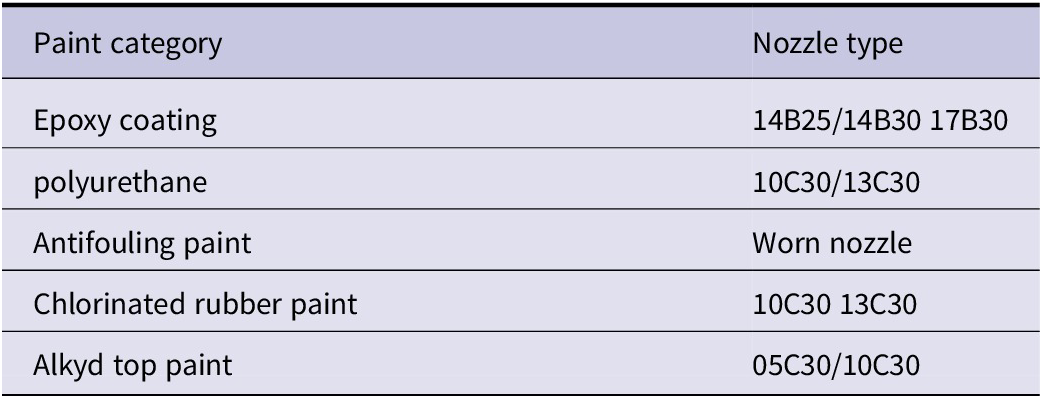


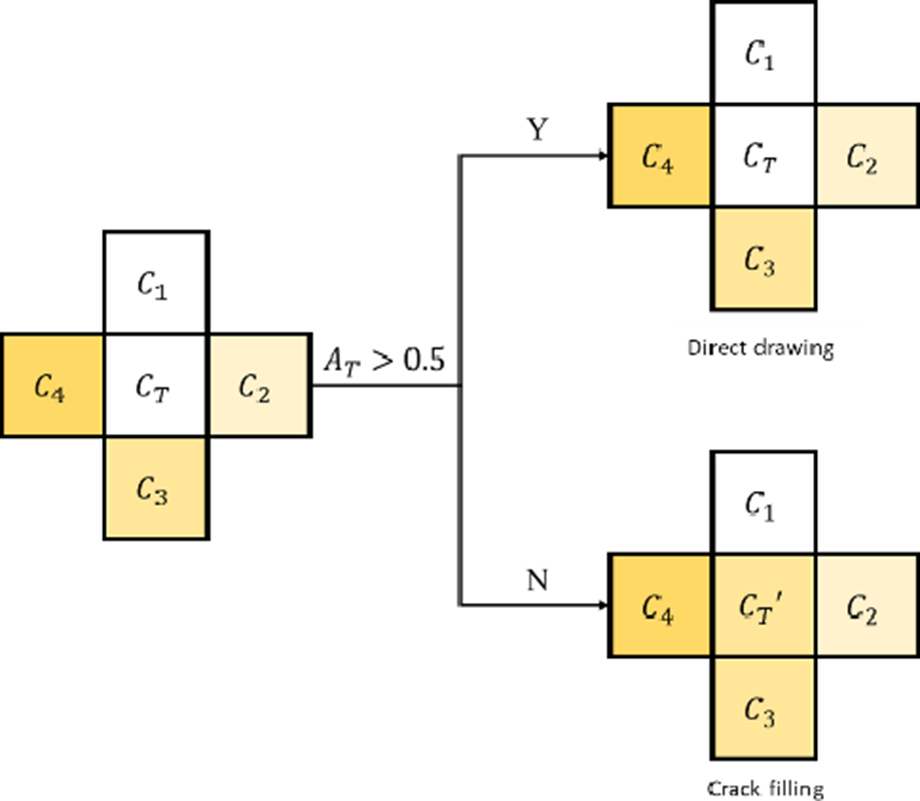


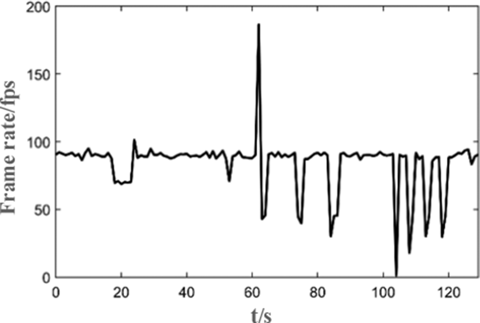

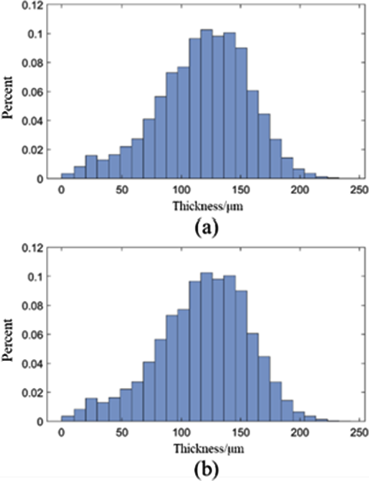


 Open access