





Introduction
Many renewable energy sources, especially those used for electricity generation, such as solar, wind, or hydropower, are not continuously available (Trainer, Reference Trainer2017; Chakraborty et al., Reference Chakraborty, Dawn, Saha, Basu and Ustun2022). For this reason, rapid development of efficient electricity storage technologies is essential to buffer the mismatch between production and demand.
Lithium-ion batteries currently provide the greatest energy density among commercial storage devices. Nevertheless, they face several challenges: global lithium and cobalt reserves are limited, and recycling of these materials is complex and resource-intensive (Deguenon et al., Reference Deguenon, Yamegueu, Moussa Kadri and Gomna2023). Furthermore, lithium-ion batteries carry a risk of spontaneous combustion (Chakraborty et al., Reference Chakraborty, Dawn, Saha, Basu and Ustun2022). Another issue is their degradation during repeated charge–discharge cycles, which leads to a gradual reduction in performance (Trainer, Reference Trainer2017).
Electrochemical double-layer capacitors (EDLCs) offer alternative energy storage technology (Chakraborty, Reference Chakraborty2003). They provide significantly greater energy density than conventional capacitors, although less than that of batteries (Schoetz et al., Reference Schoetz, Gordon, Ivanov, Bund, Mandler and Messinger2022). Conventional EDLCs typically exhibit energy densities of the order of 5–20 Wh kg–1 (Han et al., Reference Han, Fang, Chu, Wang and Ostrikov2023) By comparison, lithium-polymer batteries generally achieve much greater specific energy, of the order of 100–250 Wh kg–1 (Wong et al., Reference Wong, Sunarso, Wong, Lin, Yu and Jia2018; Han et al., Reference Han, Fang, Chu, Wang and Ostrikov2023). A key advantage of EDLCs over rechargeable batteries is their exceptional cycle stability (Chakraborty, Reference Chakraborty2003).
Current research efforts aim to combine multiple charge-storage mechanisms within a single device to bridge the gap between capacitors (large specific power) and batteries (large specific energy) (Schoetz et al., Reference Schoetz, Gordon, Ivanov, Bund, Mandler and Messinger2022).
Double-layer capacitance arises from charge separation in the Helmholtz double layer, located at the interface between the electrode surface and the electrolyte. Solvent molecules adhere to the electrode surface, forming an impermeable barrier between the electrode and the solvated ions in the electrolyte (Zhai et al., Reference Zhai, Zhang, Du, Ren, Xu, Wang, Miao and Liu2022). Compared with conventional capacitors, double-layer capacitors possess a very large specific surface area, when porous carbon materials are used, and an extremely thin separator barrier, of the order of a few Ångströms thick, which allows them to achieve much greater energy density than conventional capacitors (Yadi et al., Reference Yadi, Jiangmin, An, Wu, Dou, Zhang, Zhang, Wu, Dong, Zhang and Guo2020).
Supercapacitors can combine both double-layer capacitance and faradaic charge-storage mechanisms. In parallel with double-layer capacitance, faradaic processes occur when desolvated or adsorbed ions transfer electrons to the electrode surface (Schoetz et al., Reference Schoetz, Gordon, Ivanov, Bund, Mandler and Messinger2022). Pseudocapacitance may be observed in carbon electrodes when charge intercalation occurs between graphite platelets or when desolvated ions are trapped within carbon pores. This pseudocapacitance can be significantly enhanced through the use of nanostructured carbon pores that are compatible with the size of solvated ions. Such pores facilitate electron transfer from desolvated ions to the electrode (Liu et al., Reference Liu, Yang, Wu, Wang, Li, Ma and Zhou2022; Supiyeva et al., Reference Supiyeva, Pan and Abbas2023).
Double-layer capacitors based on clay and conductive carbon black have been developed. These systems store energy exclusively through the formation of an electrical double layer, without involving faradaic charge-storage mechanisms (Kanbara et al., Reference Kanbara, Yamamoto, Tokuda and Aoki1987). Several types of electrically conductive carbon materials were used in the manufacture of supercapacitor electrodes; however, for applications involving mineral compounds such as clay (Kanbara et al., Reference Kanbara, Yamamoto, Tokuda and Aoki1987) or Portland cement-based supercapacitor electrodes (Chanut et al., Reference Chanut, Stefaniuk, Weaver, Zhu, Shao-Horn, Masic and Ulm2023), Ketjenblack EC-600JD nano carbon black was preferred.
The present study aimed to utilize clayey soil combined with carbon black as an electrode material for supercapacitors. The use of clays in supercapacitor electrodes has thus far been studied only to a limited extent due to their low electrical conductivity (Maiti et al., Reference Maiti, Pramanik, Chattopadhyay, De and Mahanty2016). Nevertheless, clays have diverse properties that indicate their potential as supercapacitor electrode material:
-
(1) Fine particle size and large surface area: clay minerals exhibit exceptionally fine grain sizes down to the nanometer range and possess very large specific surface areas, ranging from 5 to 800 m² g–1 for commonly used clays (Kuo and Liao, Reference Kuo and Liao2006).
-
(2) The presence of vacant crystallographic sites: these enable adsorption of charges on clay surfaces (Velde, Reference Velde and Velde1995).
-
(3) Possible internal charge absorption: charge storage may also occur through absorption into internal crystallographic sites or by intercalation between clay layers (Velde, Reference Velde and Velde1995).
-
(4) Large reservoir porosity: this property can facilitate effective ion diffusion within electrolyte-filled pore spaces.
-
(5) Hydrophilicity and chemical stability: clays interact well with aqueous electrolytes and are resistant to aggressive substances, allowing the use of acidic, basic, or neutral salt solutions as electrolytes.
-
(6) Surface conductivity: compared with other sediments, clays exhibit relatively high electrical conductivity in the presence of water due to surface conduction associated with vacant sites in the octahedral sheet (Qi and Wu, Reference Qi and Wu2022).
-
(7) Economic and environmental benefits: clay resources are abundant and widely available worldwide, making them a cost-effective and sustainable electrode material.
Recent reviews have highlighted the growing interest in clay-based and clay-derived materials for electrochemical energy storage and conversion. Lan et al. (Reference Lan, Liu, Li, Chen, He and Parkin2021) provided a comprehensive overview of natural clay-based materials, discussing their structure, modification strategies, and applications as electrodes, electrolytes, and separators in batteries and supercapacitors.
Clays can contribute to electrical energy storage in supercapacitors through several mechanisms. For example, montmorillonite intercalated with Fe2+/3+ ions has been used to construct an asymmetric, flexible, all-solid-state supercapacitors exhibiting redox properties (Luo et al., Reference Luo, Hsu, Gan, Pao, Lee, Wang, Lin, Chen, Wu and Chuang2023). Supercapacitors were developed (Maiti et al., Reference Maiti, Pramanik, Chattopadhyay, De and Mahanty2016) from acid-leached montmorillonite K10, carbon nanotubes, and MnO2. Supercapacitors were fabricated (Chai et al., Reference Chai, Zhang, Yang, Zhang, Han, Theint and Ma2023) from eight different clay minerals – kaolinite, halloysite, montmorillonite, vermiculite, attapulgite, sepiolite, talc, and chlorite – intercalated with CeO2 nanoparticles. They proposed that both double-layer capacitance, involving H⁺ adsorption/desorption on the CeO2 surface, and faradaic charge-storage mechanisms, involving intercalation and deintercalation of H⁺ into CeO₂, contributed to energy storage. Those authors concluded that tetrahedral-octahedral-tetrahedral (TOT) nanosheet clays exhibit greater potential for supercapacitor applications due to their crystal arrangement and larger BET surface area. However, the greatest capacitance was observed for nanorod-shaped halloysite which exposed silicon–oxygen groups, and surface defects provide active sites for charge adsorption (Chai et al., Reference Chai, Zhang, Yang, Zhang, Han, Theint and Ma2023). More recently, Wu et al. (Reference Wu, He, Zhao, Huang, Tong, Liao and Pang2024) reviewed montmorillonite- and smectite-based materials for electrochemical energy storage, emphasizing the role of layered structures, ion transport, and interlayer chemistry in charge-storage behavior. In addition, Liao et al. (Reference Liao, Chai and Zhang2024) demonstrated that chemical modification of clay minerals, including controlled expansion of layer spacing, can significantly influence electrochemical capacitance in supercapacitor electrodes. Smectitic clays are known for their pronounced swelling when water or other polar molecules enter the interlayer space (Al Kausor et al., Reference Al Kausor, Sen Gupta, Bhattacharyya and Chakrabortty2022). This suggests that solvated K⁺ ions from electrolytes such as KCl may access the interlayer regions (Ahlersmeyer et al., Reference Ahlersmeyer, Clay, Kovács, Osterloh, Moradi Rekabdarkolaee and Clark2025) and potentially contribute to charge storage in supercapacitor electrodes.
In studies where clay is combined solely with conductive carbon, without the incorporation of metal oxides or other redox-active species, charge storage is typically dominated by electrical double-layer capacitance, with no significant faradaic contribution. Devices operating under these conditions are therefore classified as double-layer capacitors. Such a system was demonstrated by Kanbara et al. (Reference Kanbara, Yamamoto, Tokuda and Aoki1987) using kaolinitic clay and carbon black, identifying a composite containing 15 wt.% carbon black as the optimal formulation. The distribution of carbon black in porous carbon–clay composites was analyzed by Kanbara et al. (Reference Kanbara, Yamamoto, Ikawa, Tagawa and Imai1989) and those authors proposed two possible modes of electrical current flow: (1) conduction via particles dispersed in the insulating clay matrix; and (2) conduction along carbon chains within the clay. Electrical conductivity measurements as a function of the carbon black volume fraction indicated which mode predominates. The results suggest that both randomly distributed carbon particles and carbon chains co-exist, with current primarily flowing along the carbon chains (Kanbara et al., Reference Kanbara, Yamamoto, Ikawa, Tagawa and Imai1989).
In the study of Kanbara et al. (Reference Kanbara, Yamamoto, Tokuda and Aoki1987), clay–carbon black electrodes were fired in an argon atmosphere to prevent carbon oxidation. In contrast, the present study does not use firing in an inert atmosphere. Raw or calcined/chemically activated powdered clays were mixed directly with carbon black and aqueous electrolytes to form paste electrodes. Furthermore, this study examines systematically the influence of clay mineralogy, activation, and electrolyte chemistry on electrochemical performance and links XRD-observed mineralogical changes to variations in cyclic voltammetry.
Aside from carbon–clay composites, a carbon-doped Portland cement composite that functions both as a construction material and as a supercapacitor has been developed (Chanut et al., Reference Chanut, Stefaniuk, Weaver, Zhu, Shao-Horn, Masic and Ulm2023). Those authors evaluated various parameters, including the type and amount of carbon, electrode thickness, and the water-to-cement ratio. Optimal capacitance was achieved when Ketjenblack EC-600JD was used as the carbon source, with a carbon black-to-cement mass ratio of 0.128, a water-to-cement ratio of 1.4, and an electrode thickness of 6 mm (Chanut et al., Reference Chanut, Stefaniuk, Weaver, Zhu, Shao-Horn, Masic and Ulm2023).
This study addresses a knowledge gap concerning the potential use of clays in the fabrication of supercapacitor electrode materials, as only a limited number of studies have investigated clays for this application. Despite their abundance, low cost, and tunable physicochemical properties, the electrochemical performance of clay-based materials in supercapacitor electrodes remains insufficiently explored.
The hypothesis tested in this work is that clays can be combined effectively with carbon materials to fabricate supercapacitor electrodes. In such composites, clays are expected to contribute to capacitance through electrical double-layer formation and additional faradaic charge-storage mechanisms, leading to capacitance values exceeding those of purely carbon-based electrical double-layer electrodes.
To test this hypothesis, supercapacitor electrodes were prepared using kaolinitic, illitic, and smectitic clays. For each clay type, raw as well as calcined/acid-treated materials were examined. The resulting clay–carbon composite electrodes were evaluated in acidic (H2SO4), basic (KOH), and neutral (KCl) electrolytes.
The results show that capacitance varies as a function of clay mineralogical composition, treatment method, and electrolyte type. In addition, extra anodic currents were observed in the cyclic voltammograms, indicating the presence of faradaic charge-storage processes.
Materials and methods
In the present study, kaolinitic clay obtained from a quarry in southwestern Germany, illitic clay from the Liepa deposit in central Latvia, and commercially available acid-leached smectitic clay (Montmorillonite K10) were used. The illitic clay originating from the Liepa deposit in central Latvia dates back to the Devonian period and is widely exploited by Lode SIA for the production of various construction materials. The mineralogical composition of the Liepa clay is dominated by illite, although quartz, feldspar, kaolinite, and muscovite are also present.
The kaolinitic clay was obtained from a quarry operated by Rech Kies-GmbH in southwestern Germany. This material is removed as overburden during gravel and sand extraction and is mostly landfilled as mining waste. In addition to kaolinite, the clay contains quartz, illite/muscovite, and feldspar.
The commercial acid-leached smectitic clay, montmorillonite K10, was purchased from Sigma-Aldrich. This material was also employed by Maiti et al. (Reference Maiti, Pramanik, Chattopadhyay, De and Mahanty2016) in the preparation of supercapacitor electrodes. Besides smectite, this material also contains quartz, muscovite, and feldspar as other constituents.
The chemical compositions of the three clays were determined by X-ray fluorescence (XRF) analysis (Table 1). The major elemental composition of the powdered samples was measured using a sequential X-ray fluorescence spectrometer (PANalytical MagiXPro). Major element contents are reported as oxide weight percentages on an LOI (loss on Ignition)-free basis.
Chemical composition of three different clays used as supercapacitor electrodes (wt.% on an LOI-free basis)

Table 1. Long description
From the top row, the table lists three clay types: Kaolinitic (Rech) clay, Illitic (Liepa) clay, and Smectitic clay montmorillonite K10. Each row presents values for S i O sub 2, T i O sub 2, A l sub 2 O sub 3, F e sub 2 O sub 3, M g O, C a O, N a sub 2 O, K sub 2 O, and L O I. Kaolinitic clay contains 71.70 S i O sub 2, 1.46 T i O sub 2, 21.15 A l sub 2 O sub 3, 1.36 F e sub 2 O sub 3, 0.40 M g O, 0.10 C a O, 0.15 N a sub 2 O, 2.99 K sub 2 O, and 6.07 L O I. Illitic clay contains 74.11 S i O sub 2, 0.93 T i O sub 2, 13.58 A l sub 2 O sub 3, 5.16 F e sub 2 O sub 3, 1.03 M g O, 0.23 C a O, 0.04 N a sub 2 O, 3.77 K sub 2 O, and 4.66 L O I. Smectitic clay montmorillonite K10 contains 72.46 S i O sub 2, 0.58 T i O sub 2, 18.46 A l sub 2 O sub 3, 3.17 F e sub 2 O sub 3, 1.46 M g O, 0.36 C a O, 0.32 N a sub 2 O, 1.80 K sub 2 O, and 13.28 L O I. The values are given in weight percent on an L O I-free basis.
LOI: loss on ignition
SiO2 is the most abundant oxide in all samples, and its concentration is relatively similar across the materials. Al2O3 shows the highest concentration in the Rech clay, while Fe2O3 is most prominent in the Liepa clay. K2O is also comparatively abundant in all analyzed clay minerals.
For the identification of mineral phases, a Bruker D6 Phaser X-ray diffractometer was used. Cyclic voltammetry (CV) measurements were carried out using a Gamry 1010E potentiostat operated in the two-electrode configuration.
The morphology of the carbon-doped clay sample was examined by scanning electron microscopy (SEM; LEO 435 VP) at 25 kV. Samples were air-dried and gold-coated before imaging; SEM was used to examine particle morphology, surface texture, and the dispersion of carbon black within the clay matrix.
Rather than focusing solely on electric double-layer capacitance, the clays were calcined and acid-activated to enable additional faradaic charge-storage mechanisms.
A study on the acidification and intercalation of illite from the Liepa deposit in Latvia was conducted by Trubača-Boginska et al. (Reference Trubača-Boginska, Ādiņa, Vaivars and Švirksts2018). The authors performed purification, acidification, and intercalation with DMSO (dimethyl sulfoxide) and concluded that potassium ions are strongly bound within the interlayer space of the illite. As a result, intercalation and exfoliation are difficult, and no intercalation of cations was observed (Trubača-Boginska et al., Reference Trubača-Boginska, Ādiņa, Vaivars and Švirksts2018). Zhen et al. (Reference Zhen, Jiang, Li and Xue2017) also investigated the intercalation and exfoliation of illite. In their study, illite was purified, calcined activated at 600°C for 1 h, and acidified with nitric acid. The samples were subsequently intercalated and exfoliated using four intercalating agents: glycerol, hydrazine hydrate, DMSO, and urea. During high-temperature ultrasonic treatment, the intercalated molecules were deintercalated, resulting in the exfoliation of illite layers (Zhen et al., Reference Zhen, Jiang, Li and Xue2017). The authors proposed that H⁺ ions from nitric acid may exchange some of the interlayer K⁺ ions during acid treatment.
Calcination was considered as one strategy for clay activation in this work. During heating at elevated temperatures, the hydroxyl groups of clay minerals are removed (Li et al., Reference Li, Lu, Nkoh Nkoh and Xu2023), leading to increased structural disorder and exposure of active sites (Adesina et al., Reference Adesina, Volaity, Aylas-Paredes, Qi, Kumar and Neithalath2025). However, calcination of common clay minerals typically reduces the magnitude of their negative zeta potential, resulting in values close to zero (Sposito et al., Reference Sposito, Maier, Beuntner and Thienel2021). The dehydroxylation temperature of kaolinite is 550–650°C (Chakraborty, Reference Chakraborty2003), while that of montmorillonite is ~670°C (Guggenheim and Van Groos, Reference Guggenheim and Van Groos1992). Furthermore, calcination of montmorillonite at elevated temperatures decreases its swelling capacity and leads to shrinkage of the electrical double layer (Chen et al., Reference Chen, Sedighi, Curvalle and Jivkov2024).
The selection of an optimal electrolyte can increase the energy density of a supercapacitor even more effectively than improving electrode capacitance, as energy density is proportional to the square of the cell voltage (Thomas et al., Reference Thomas, Vigneshwaran, Abinaya, Rajendran, Jose, Cherusseri, Krishnan, Pham and Dubal2024). Aqueous electrolytes offer significant ionic conductivity, low cost, and low toxicity, but their main limitation is a narrow operating potential window restricted to 1.23 V (Pang et al., Reference Pang, Jiang, Zhao, Zhang, Wang, Li, Liu, Pan, Qu and Xing2020; Thomas et al., Reference Thomas, Vigneshwaran, Abinaya, Rajendran, Jose, Cherusseri, Krishnan, Pham and Dubal2024). Organic and ionic liquid electrolytes can achieve much wider operating potential windows (~3.0 V), allowing a substantial increase in energy density. However, organic electrolytes are frequently flammable and toxic, while ionic liquids suffer from high viscosity and low ionic conductivity (Pang et al., Reference Pang, Jiang, Zhao, Zhang, Wang, Li, Liu, Pan, Qu and Xing2020).
Aqueous electrolytes are commonly classified as neutral (e.g. Na2SO4, Li2SO4, NaNO3, KCl), acidic (e.g. HCl, H2SO4), or alkaline (e.g. KOH) (Thareja and Kumar, Reference Thareja and Kumar2021; Zhang et al., Reference Zhang, Tan, Zhang, Pan, Wang and Le2022; Chanut et al., Reference Chanut, Stefaniuk, Weaver, Zhu, Shao-Horn, Masic and Ulm2023). Taer et al. (Reference Taer, Febriyanti, Apriwandi, Agustino and Sinta Mustika2021) compared the performance of activated carbon electrodes in 1 M H₂SO₄ and KOH electrolytes and found that H₂SO₄ is better suited to biomass-derived carbon electrodes. Chai et al. (Reference Chai, Zhang, Yang, Zhang, Han, Theint and Ma2023) used CeO₂-montmorillonite clay electrodes with H2SO4 electrolyte and identified two capacitance contributions: (1) double-layer capacitance from H⁺ adsorption/desorption on the CeO2 surface; and (2) faradaic charge storage via highly reversible redox reactions where H⁺ ions intercalate into CeO2 due to their small ionic radius.
In the study by Chanut et al. (Reference Chanut, Stefaniuk, Weaver, Zhu, Shao-Horn, Masic and Ulm2023), 1 M KCl solution was used as the electrolyte for Portland cement–carbon black composites because of its relatively large diffusion coefficient and neutral pH. KCl was also one of the electrolytes employed in the earlier work of Kanbara et al. (Reference Kanbara, Yamamoto, Tokuda and Aoki1987).
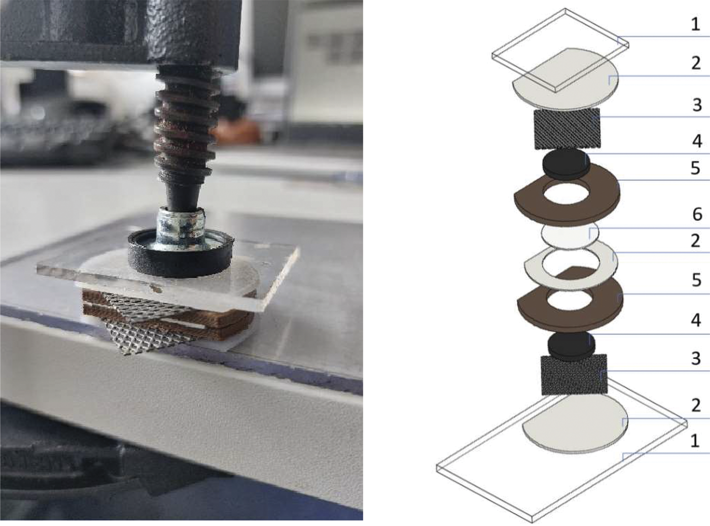
In the present study, the symmetric supercapacitor cell consisted of two identical electrodes with a diameter of 18 mm and a thickness of 2.5 mm, giving a total cell volume of 1.27 cm³ (Fig. 1). The electrode material was filled into two acrylonitrile-styrene-acrylate (ASA) rings, separated by a porous fiberglass membrane in the center. Each side of the assembly was covered with platinum-coated titanium mesh current collectors, which provided electrical contact between the electrodes and the potentiostat.
Design of the supercapacitor: (1) insulating glass plates; (2) silicone sealing membranes; (3) platinum-coated titanium mesh current collectors; (4) electrodes composed of clay, carbon black, and electrolyte; (5) acrylonitrile styrene acrylate (ASA) rings; and (6) porous fiberglass membrane.

Figure 1. Long description
The left panel displays a close-up photo of a supercapacitor being compressed by a clamp, showing stacked layers including a transparent plate, mesh, and dark sealing elements. The right panel is a labeled exploded diagram with six types of components. From the bottom upward: the base is an insulating glass plate labeled 1, followed by a silicone sealing membrane labeled 2, a platinum-coated titanium mesh current collector labeled 3, an electrode layer of clay, carbon black, and electrolyte labeled 4, an acrylonitrile styrene acrylate ring labeled 5, a porous fiberglass membrane labeled 6, another silicone sealing membrane labeled 2, another acrylonitrile styrene acrylate ring labeled 5, a second electrode layer labeled 4, a second mesh current collector labeled 3, another silicone sealing membrane labeled 2, and a top insulating glass plate labeled 1. Each component is separated and numbered, illustrating the assembly sequence from bottom to top.
Silicone sealing membranes and glass plates were used to insulate the cell and to distribute pressure evenly when the assembly was fixed together with screw-clamp to ensure mechanical stability and proper sealing of all components. The compression force during cell assembly was controlled by applying a torque of 1 N m to the screw clamp using a torque wrench. This compression was applied solely to maintain the mechanical integrity of the cell and to ensure reproducible electrode–collector contact.
The inter-electrode spacing (~0.5 mm) was defined by a fiberglass membrane in combination with a silicone sealing membrane, which also served to prevent electrolyte leakage during testing. The fiberglass membrane was pre-soaked in the corresponding electrolyte prior to cell assembly to ensure complete wetting. The electrodes were already saturated with electrolyte during the mixing stage of clay, carbon black, and electrolyte.
Electrical contact between the electrodes and the current collectors was achieved by pressing the electrode paste into a platinum-coated wire mesh, resulting in negligible electrode-to-collector contact resistance.
Platinum-coated titanium mesh current collectors were purchased from Redox.me, Sweden, and a high-porosity fiberglass membrane with strong acid and alkali resistance was provided by Cambridge Energy Solutions. As a carbon additive, Ketjenblack EC-600JD nano carbon black was used due to its very large specific surface area (SBET = 1307 m² g–1); this carbon additive was also employed in the studies of Kanbara et al. (Reference Kanbara, Yamamoto, Tokuda and Aoki1987) and Chanut et al. (Reference Chanut, Stefaniuk, Weaver, Zhu, Shao-Horn, Masic and Ulm2023).
All electrolytes were prepared from laboratory-grade chemicals purchased from Carl Roth GmbH + Co. KG: concentrated sulfuric acid (H₂SO₄, 96–98%, p.A.), potassium hydroxide pellets (KOH, ≥85%, p.A), and potassium chloride powder (KCl, ≥99.5%, p.A). Sixty milliliters of concentrated sulfuric acid was added carefully to a 1 L volumetric flask. The solution was diluted with deionized water to the 1 L mark. The resulting solution has a pH near 0 at 25°C. KOH pellets (56.2 g) were dissolved in deionized water in a 1 L volumetric flask and diluted to the mark, resulting in pH≈14 at 25°C; 74.6 g of KCl powder was dissolved in deionized water in a 1 L volumetric flask and diluted to the mark, giving a neutral solution with pH≈7 at 25°C.
All clay samples were ground in a ball mill for 30 s. Kaolinitic, illitic, and smectitic clays were calcined in a LINN VMK 22 muffle furnace. The ground clay powder was placed in porcelain crucibles. The furnace temperature was increased to 800°C over 1.5 h, followed by calcination at 800°C for 1 h in an oxidizing atmosphere. After calcination, the furnace was switched off and the samples were allowed to cool naturally for ~6 h. The procedure for activation of illitic clay was adapted from Zhen et al. (Reference Zhen, Jiang, Li and Xue2017). The clays in the present study were not purified or intercalated/exfoliated (as they were in the Zhen et al. (Reference Zhen, Jiang, Li and Xue2017) study), and the calcination temperature was increased to 800°C, as this was identified by Kanbara et al. (Reference Kanbara, Yamamoto, Ikawa, Tagawa and Imai1989) as the optimum temperature for obtaining electrically conductive, porous clay–carbon black composites. Raw illitic clay was ground, calcined, and subsequently acidified with 2 M nitric acid at 95°C for 3 h, followed by washing to neutral pH and drying.
Mixing was performed using a laboratory mortar mixer. Three compounds (clay, carbon black, and electrolyte) were mixed for 30 min at a speed of 285±10 rpm (corresponding to ~6 g , estimated based on the stirrer geometry). For mixtures containing clay, mechanical mixing was applied, whereas an agate mortar was used when mixing carbon black with the electrolyte alone.
A total of 18 mixing scenarios was prepared using the three clays and three electrolytes. The proportions of clay, carbon black, and electrolyte were kept constant across all mixing scenarios (Table 2).
Mix design of electrode material containing clays, carbon black, and electrolyte (1); and containing pure carbon black with electrolyte (2)

Table 2. Long description
Column headers from left to right are No., Clay (weight percent), Carbon black (weight percent), Electrolyte (weight percent), Carbon black to clay ratio, and Liquid to clay ratio. Row 1 shows mix 1 with clay at 38.1 percent, carbon black at 4.8 percent, electrolyte at 57.1 percent, carbon black to clay ratio at 0.125, and liquid to clay ratio at 1.5. Row 2 shows mix 2 with clay not applicable, carbon black at 11.11 percent, electrolyte at 88.89 percent, and both ratios not applicable.
The carbon black/clay ratio was selected based on the optimal carbon/cement ratio reported by Chanut et al. (Reference Chanut, Stefaniuk, Weaver, Zhu, Shao-Horn, Masic and Ulm2023). The electrolyte content was adjusted to ensure adequate workability and high paste porosity while avoiding segregation of clay, quartz, or carbon black. The paste was cast into two acrylonitrile–styrene–acrylate rings (18 mm internal diameter, 2.5 mm thickness) following Kanbara et al. (Reference Kanbara, Yamamoto, Tokuda and Aoki1987), separated by a porous membrane and connected via platinum-coated titanium mesh collectors. Cyclic voltammetry was performed using a Gamry 1010E potentiostat at scan rates of 1, 5, and 20 mV s–1, with the potential limited to 1.0 V to prevent oxygen evolution due to water electrolysis.
Relatively low scan rates were used to ensure that ion diffusion within the clay–carbon composite is fully captured and that slower electrochemical processes, such as surface redox reactions and electrode relaxation, are reflected in the observed current. Measured currents were normalized to the total cell volume (1.27 cm³) to obtain volumetric current densities.
The density of the electrode materials was determined by filling the viscous electrode paste into an acrylonitrile–styrene–acrylate (ASA) ring with a diameter of 2.8 cm and a height of 1.0 cm. The mass of each filled ring was measured using a digital balance with a precision of 0.01 g. Three replicate measurements were performed for each mixture, and the average mass was used to calculate the density based on the known volume of the ASA ring.
Results
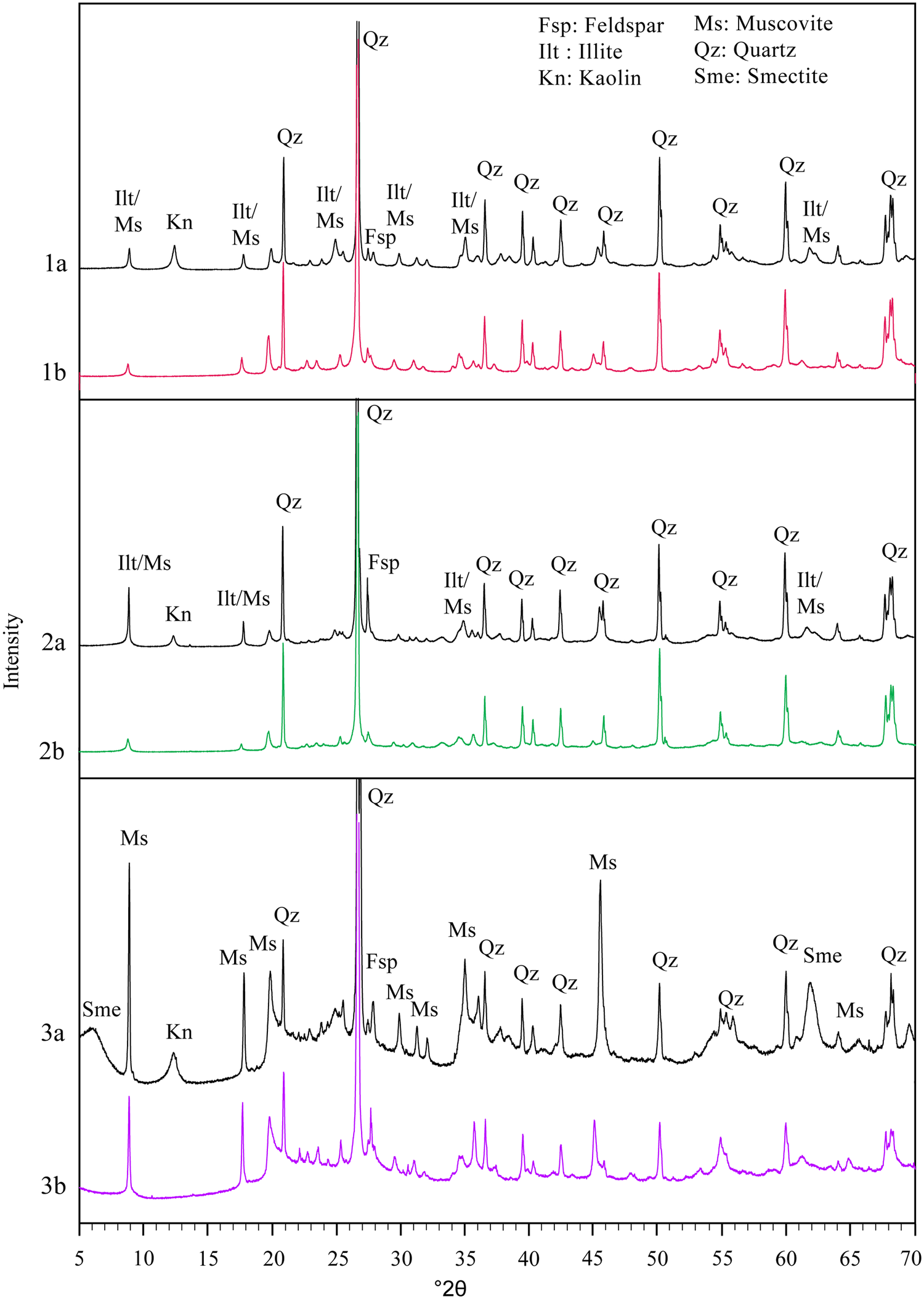
X-ray diffraction patterns were obtained for raw kaolinitic clay and the same clay calcined at 800°C (Fig. 2-1a, 2-1b). The characteristic kaolinite peaks disappeared completely after calcination, while the intensity of illite reflections decreased. Comparing raw illitic clay from the Liepa deposit and the same clay after calcination and acidification (Fig. 2-2a, 2-2b), one can observe that kaolinite reflections at d = 7 Å and d = 3.5 Å were no longer observed, and illite peaks at d = 10 Å and d = 5 Å were reduced significantly. The XRD patterns of uncalcined and calcined smectitic clay (Fig. 2-3a, 2-3b) show that calcination at 800°C caused the smectite peaks to disappear as the interlayer spacing collapsed to d ≈ 10 Å. After calcination at 800°C, the smectite reflections were no longer detectable by XRD (Fig. 2). Calcination at this temperature efficiently dehydroxylates smectite by removing the octahedral Al-OH groups and breaking the layered framework. This process reduces the degree of crystallinity and converts smectite into a more reactive amorphous form (Slaný et al., Reference Slaný, Kuzielová, Žemlička, Matejdes, Struhárová and Palou2023; Panzer et al., Reference Panzer, Scherb, Beuntner and Thienel2024; Sayed et al., Reference Sayed, Ramadan and Mohsen2025).
XRD patterns of raw and activated clays: kaolinitic clay (1a: raw; 1b: calcined at 800°C); illitic clay (2a: raw; 2b: calcined at 800°C and treated with HNO₃); and smectitic clay (3a: uncalcined; 3b: calcined at 800°C).

Figure 2. Long description
The graph contains three vertical panels, each with two overlaid X R D patterns. The X axis is labeled two theta in degrees, ranging from 5 to 70. The Y axis is labeled intensity. Top panel: 1a (black) is raw kaolinitic clay, 1b (red) is kaolinitic clay calcined at 800 degrees Celsius. Middle panel: 2a (black) is raw illitic clay, 2b (green) is illitic clay calcined at 800 degrees Celsius and treated with H N O sub 3. Bottom panel: 3a (black) is uncalcined smectitic clay, 3b (magenta) is smectitic clay calcined at 800 degrees Celsius. Each pattern shows labeled peaks for minerals: Qz for quartz, Fsp for feldspar, Ms for muscovite, Ilt for illite, Kn for kaolin, Sme for smectite. In all panels, the most intense peak is Qz near 26 degrees two theta. Calcination generally reduces the intensity of clay mineral peaks and increases the relative intensity of quartz. The legend at the top right defines all mineral abbreviations.
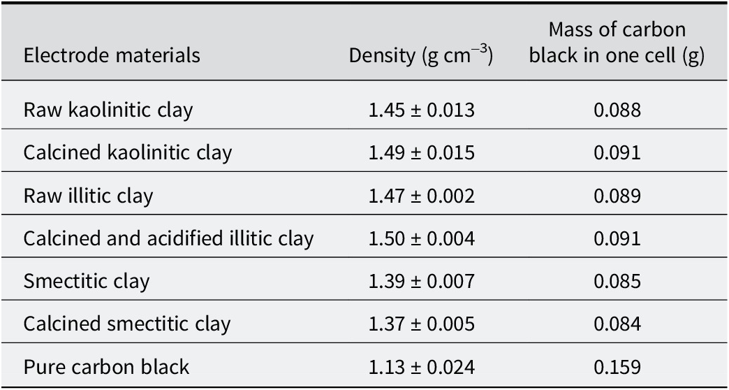
Density was measured for viscous pastes containing carbon black, electrolyte, and various clay minerals with various treatments (Table 3). The lowest density was observed for mixtures containing smectitic clay (excluding pure carbon black electrodes, which exhibit even lower density), whereas calcined illitic clay exhibited the highest density. Notably, the carbon-doped electrode contains ~55–57% of the carbon mass compared with the pure carbon electrode (Table 3).
Density of electrodes composed of clay, carbon black, and electrolyte depending on materials used for electrode preparation
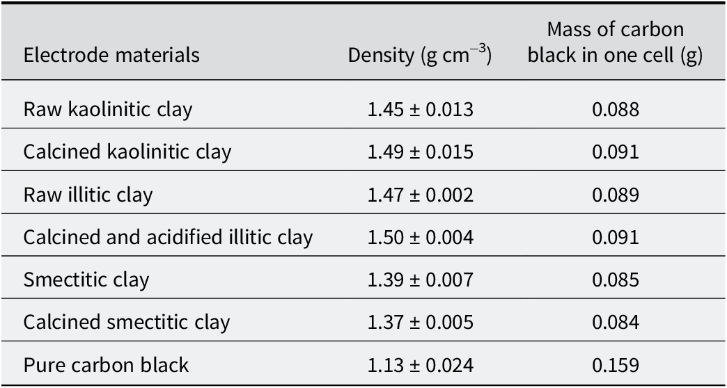
Table 3. Long description
Beginning at the top row, the table lists electrode materials in the first column: raw kaolinitic clay, calcined kaolinitic clay, raw illitic clay, calcined and acidified illitic clay, smectitic clay, calcined smectitic clay, and pure carbon black. The second column presents density in grams per cubic centimeter with uncertainty: raw kaolinitic clay is 1.45 plus or minus 0.013, calcined kaolinitic clay is 1.49 plus or minus 0.015, raw illitic clay is 1.47 plus or minus 0.002, calcined and acidified illitic clay is 1.50 plus or minus 0.004, smectitic clay is 1.39 plus or minus 0.007, calcined smectitic clay is 1.37 plus or minus 0.005, and pure carbon black is 1.13 plus or minus 0.024. The third column shows mass of carbon black in one cell in grams: raw kaolinitic clay is 0.088, calcined kaolinitic clay is 0.091, raw illitic clay is 0.089, calcined and acidified illitic clay is 0.091, smectitic clay is 0.085, calcined smectitic clay is 0.084, and pure carbon black is 0.159. The highest density is for calcined and acidified illitic clay, and the highest carbon black mass is for pure carbon black.
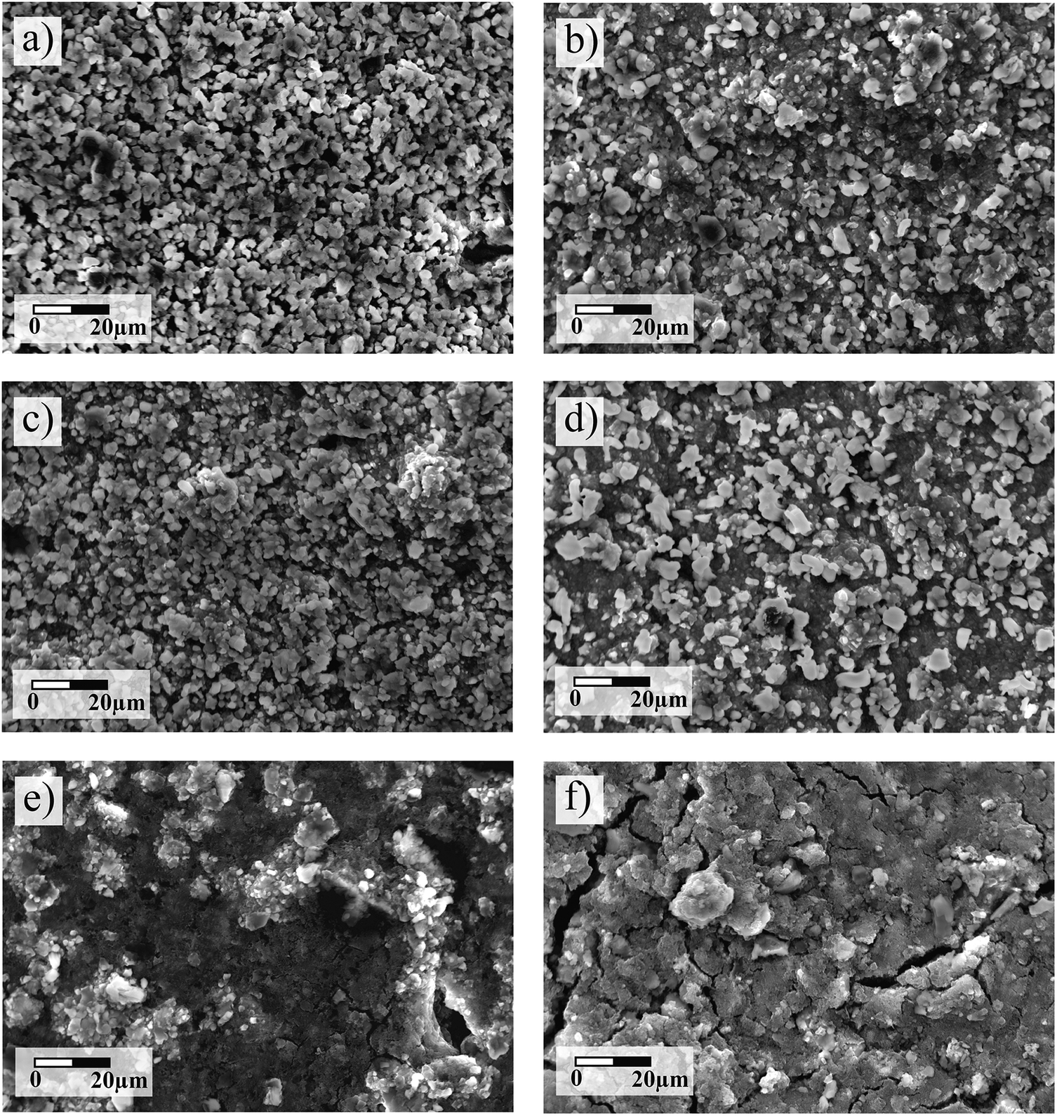
The SEM image in Fig. 3 shows that raw kaolinitic clay with carbon black appears as separate particles with only incipient aggregates (Fig. 3a), whereas the mixture with calcined clay (800°C) shows well-defined aggregates (Fig. 3b). An increase in particle size and surface area is also observed in some loose, sheet-like particles.
SEM images of samples activated with KCl: (a) raw kaolinitic clay with carbon black; (b) calcinated kaolinitic clay with carbon black; (c) raw illitic clay with carbon black; (d) calcinated illitic clay with carbon black; (e) uncalcined smectitic clay montmorillonite K10 with carbon black; (f) calcinated smectitic clay montmorillonite K10 with carbon black. For all samples, the ratio of carbon/clay is 0.125 and KCl electrolyte was used.
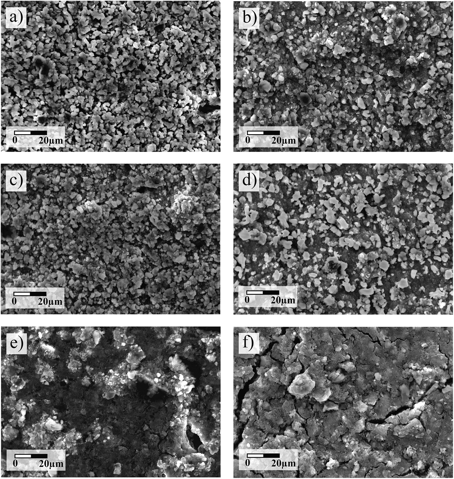
Figure 3. Long description
Panel a in the top left shows raw kaolinitic clay with carbon black, displaying densely packed, fine granular particles. Panel b to its right presents calcinated kaolinitic clay with carbon black, where particles appear slightly coarser and more angular. Panel c in the middle left shows raw illitic clay with carbon black, with a granular but less densely packed texture. Panel d to its right displays calcinated illitic clay with carbon black, where grains are more distinct and separated. Panel e in the bottom left shows uncalcined smectitic clay montmorillonite K10 with carbon black, featuring a heterogeneous surface with bright clusters and dark voids. Panel f in the bottom right presents calcinated smectitic clay montmorillonite K10 with carbon black, where the surface is rougher, with larger aggregates and visible cracks. All panels include a scale bar labeled 0 to 20 micrometers, indicating the magnification. The panels collectively illustrate morphological changes due to calcination and clay type under identical carbon to clay ratios and K C l activation.
Raw illitic clay with carbon black contains a relatively large number of aggregates (Fig. 3c). In the sample with calcined illitic clay, particle agglomeration increases markedly, with greater compactness and smoother surfaces (Fig. 3d). In this case, carbon black is observed to form chain-like networks bridging clay particles, indicating improved particle connectivity. Nonetheless, isolated particles are still present, and the sheet-like particles appear to have increased in size.
The SEM image of K10 montmorillonite (smectite) clay with carbon black shows particle aggregates distributed over an apparently homogeneous surface (Fig. 3e), where carbon black chains are also clearly visible between clay particles. In contrast, in the sample with calcined clay, the aggregates become more massive, losing the distinct shapes of the individual particles (Fig. 3f). In addition, micro-cracks are observed on the surface, probably due to dihydroxylation of the smectites during drying.
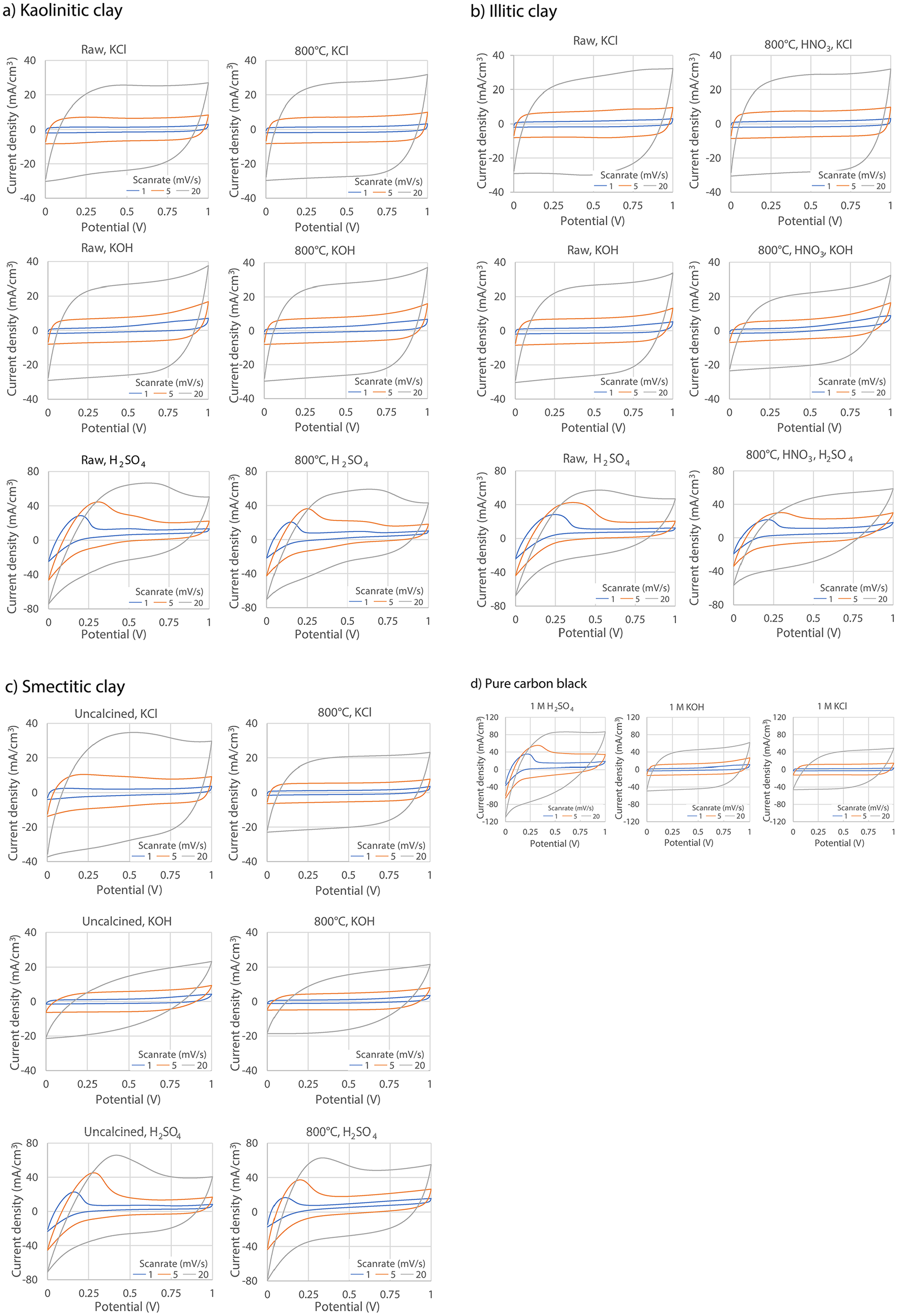
Cyclic voltammetry of the three clay–carbon black composites mixed with three different electrolytes, resulted in a total of 18 scenarios (Fig. 4). For each scenario, cyclic voltammetry was performed at scan rates of 1, 5, and 20 mV s–1.
Cyclic voltammetry of supercapacitors using: (a) raw and calcined kaolinitic clay; (b) raw and calcined/acid-treated illitic clay; (c) uncalcined and calcined smectitic clay; (d) carbon black electrodes without clay. Measurements were performed in 1 M H₂SO₄, 1 M KOH, and 1 M KCl electrolytes.
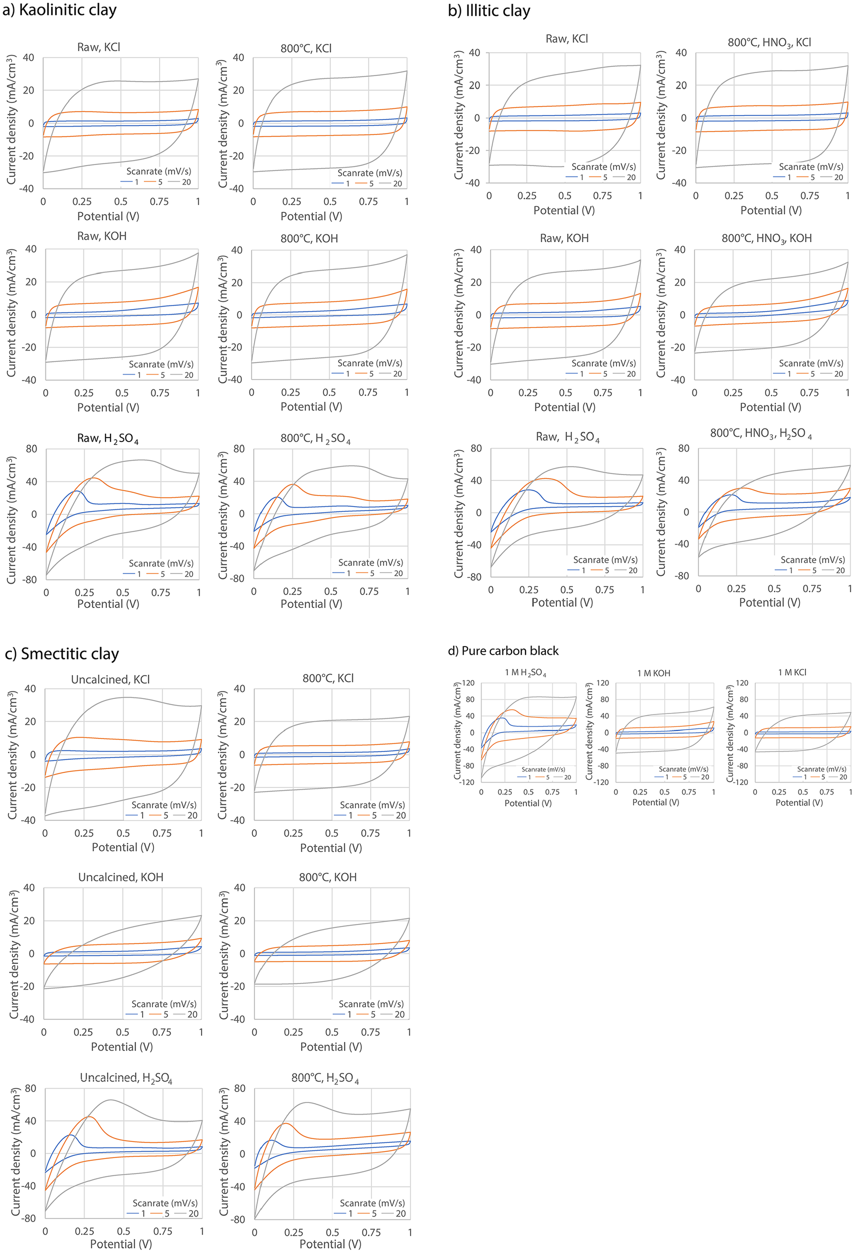
Figure 4. Long description
Panel a, titled Kaolinitic clay, contains six line graphs in a 2 by 3 grid. The x-axis is labeled Potential in volts, and the y-axis is labeled Current density in milliampere per square centimeter. The top row shows Raw K C l, 800 degrees Celsius K C l, and Raw K O H. The middle row shows 800 degrees Celsius K O H, Raw H sub 2 S O sub 4, and 800 degrees Celsius H sub 2 S O sub 4. Each graph displays three to four colored lines representing scan rates of 5, 10, and 20 millivolts per second. Current density increases with scan rate, and calcined samples generally show higher current densities than raw samples. Panel b, Illitic clay, contains six graphs in a 2 by 3 grid. The columns are Raw K C l, 800 degrees Celsius K C l, and 800 degrees Celsius H N O sub 3 K C l in the top row, and Raw K O H, 800 degrees Celsius K O H, and 800 degrees Celsius H N O sub 3 K O H in the bottom row. The third row shows Raw H sub 2 S O sub 4, 800 degrees Celsius H sub 2 S O sub 4, and 800 degrees Celsius H N O sub 3 H sub 2 S O sub 4. Current density increases with scan rate, and acid-treated samples show higher current densities. Panel c, Smectitic clay, contains six graphs in a 2 by 3 grid. The columns are Uncalcined K C l, 800 degrees Celsius K C l, Uncalcined K O H, 800 degrees Celsius K O H, Uncalcined H sub 2 S O sub 4, and 800 degrees Celsius H sub 2 S O sub 4. Current density increases with scan rate and calcination. Panel d, Pure carbon black, contains three graphs in a single row for 1 M H sub 2 S O sub 4, 1 M K O H, and 1 M K C l. All panels show that higher scan rates yield higher current densities, with the greatest enhancement observed for calcined and acid-treated clays, especially in H sub 2 S O sub 4 electrolyte.
Cyclic voltammetry of pure carbon black electrodes generally exhibited greater current densities than those of clay–carbon composite electrodes. This trend was most pronounced in the presence of H2SO4 electrolyte and can be partially attributed to the pronounced additional anodic current appearing in the potential range of ~0.1–0.25 V. An exception to the general trend was observed for electrodes based on raw smectitic clay with KCl electrolyte, which exhibited only slightly lower capacitance than the corresponding pure carbon black electrodes. An additional anodic current in the range of 0.1–0.2 V was also observed for electrodes containing raw smectitic clay when KCl was used as the electrolyte.
The cyclic voltammograms of smectitic clay–carbon electrodes, both calcined and uncalcined, displayed less rectangular shapes than those of pure carbon black electrodes in KOH electrolyte, indicating deviations from ideal double-layer capacitive behavior. By comparison, electrodes based on illitic and kaolinitic clays largely retained rectangular voltammogram shapes similar to those of pure carbon black electrodes. In H2SO4 electrolyte, all electrodes – both pure carbon black and clay–carbon composites – exhibited pronounced extra anodic currents in the potential range of 0–0.4 V, suggesting substantial contributions beyond ideal double-layer capacitance.
Volumetric capacitance (C v) by different scan rates was calculated as shown in Eqn (1):
 $$ {C}_v=\frac{A}{2kv\Delta V} $$
where A is the integrated area under the current–voltage (I–V) curve of the cyclic voltammogram at a given scan rate (expressed in A·V); k is the scan rate (V s–1), v is cell volume (cm3); and ΔV is potential window (V).
The area of cyclic voltammograms was calculated using the Integral tool of the software EC-Lab.
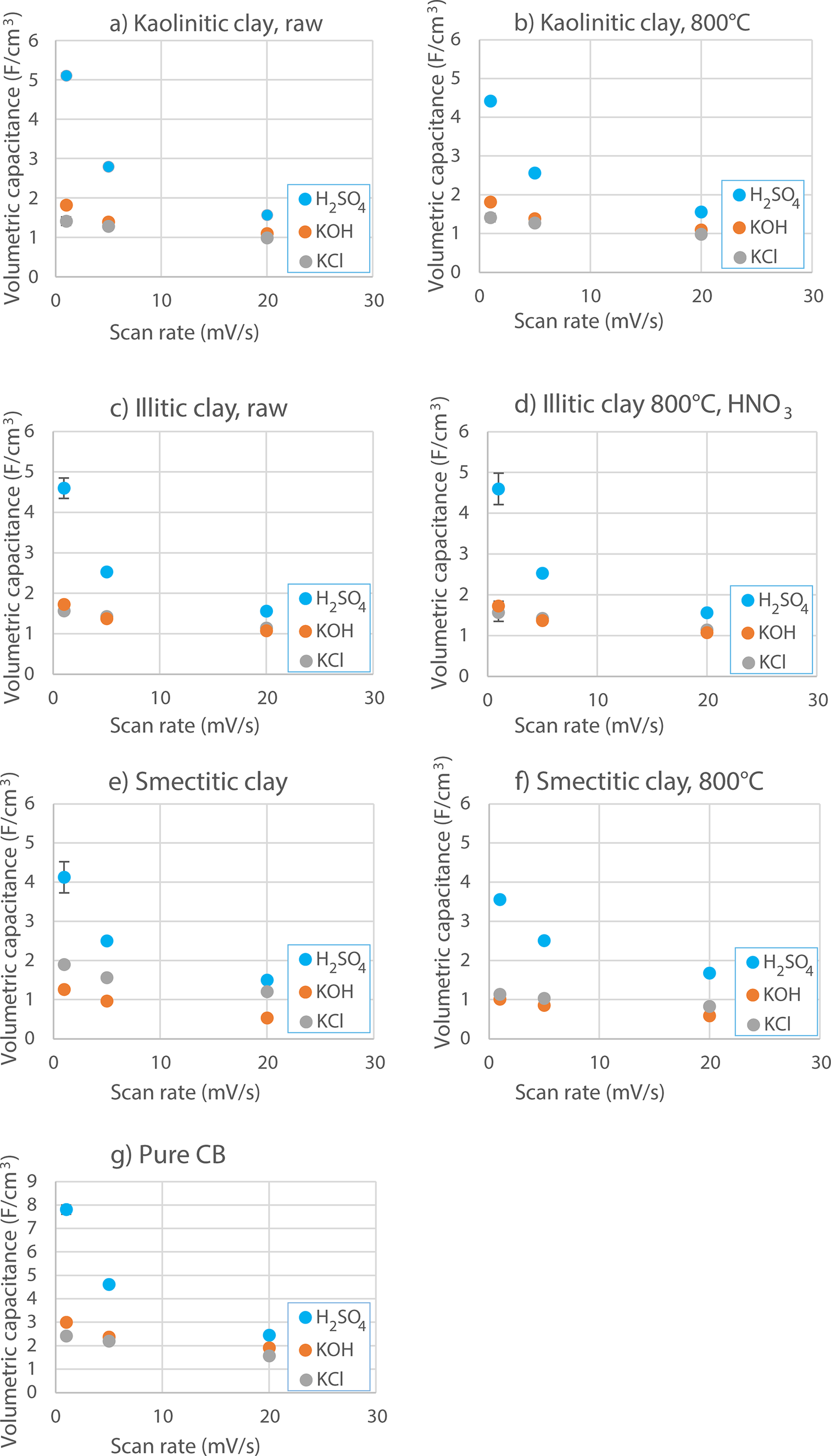
Cyclic voltammetry of the supercapacitor electrodes was performed over six cycles to ensure stabilization of the electrode response. The measurement error was calculated from the volumetric capacitance of the last three cycles, once the CV curves had stabilized. The error is more pronounced with H2SO4 as the electrolyte, while for KCl and KOH it is hardly noticeable (Fig. 5).
Volumetric capacitance (F cm–³) of supercapacitors prepared with kaolinitic clay (a: raw; b: calcined), illitic clay (c: raw; d: calcined and acidified), smectitic clay (e: uncalcined; f: calcined), and pure carbon black (g) measured in 1 M H₂SO₄, 1 M KOH, and 1 M KCl electrolytes at scan rates of 1, 5, and 20 mV s–1.
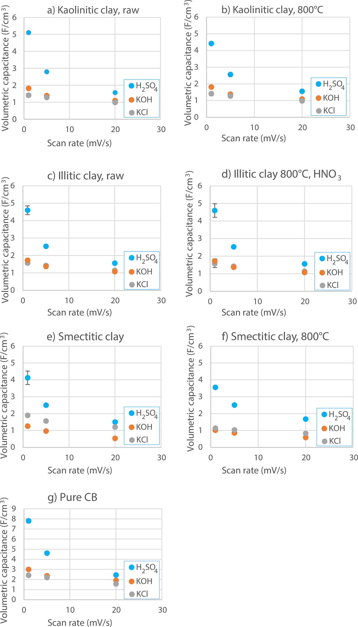
Figure 5. Long description
Starting at the top left, panel a shows kaolinitic clay raw with volumetric capacitance (F per cubic centimeter) on the y-axis and scan rate (milliVolt per second) on the x-axis. Three colored dots represent H sub 2 S O sub 4 (blue), K O H (orange), and K C l (gray) at scan rates 1, 5, and 20. H sub 2 S O sub 4 consistently yields the highest capacitance, peaking near 4 at low scan rates. Panel b, kaolinitic clay at 800 degrees Celsius, shows similar trends but with slightly lower capacitance. Panel c, illitic clay raw, displays lower overall capacitance, with H sub 2 S O sub 4 again highest. Panel d, illitic clay at 800 degrees Celsius with H N O sub 3, shows increased capacitance for H sub 2 S O sub 4, peaking above 5 at the lowest scan rate. Panel e, smectitic clay, shows moderate capacitance, H sub 2 S O sub 4 highest, others lower. Panel f, smectitic clay at 800 degrees Celsius, shows a similar pattern but with slightly higher values. Panel g, pure carbon black, shows the highest capacitance overall, with H sub 2 S O sub 4 near 8 at the lowest scan rate. Across all panels, capacitance decreases with increasing scan rate, and H sub 2 S O sub 4 consistently outperforms K O H and K C l.
Consistent with the current density measurements, the greatest capacitance was obtained for the pure carbon black electrodes (Fig. 5). Nevertheless, the difference relative to the carbon black–clay electrodes was modest, despite the fact that the carbon loading in the carbon-doped clay electrodes was ~1.8 times less than in the pure carbon electrodes. Notably, the capacitance of the smectitic clay electrode measured in KCl was nearly comparable to that of the pure carbon black electrode in the same electrolyte. Among the carbon-doped clays, the greatest capacitance was observed for kaolinitic clay in H2SO4 electrolyte. Capacitance decreased sharply with increasing scan rate. All clays exhibited greater capacitance with H2SO4; raw smectitic clay in KCl showed the next highest values. Calcined smectitic clay displayed lower capacitance than its raw counterpart, whereas the volumetric capacitance of raw and calcined kaolinitic and calcined/acidified illitic clays remained largely unchanged.
For pure carbon black electrodes, the capacitance measured in KOH electrolyte was greater than that obtained in KCl electrolyte. In contrast, smectitic clay–carbon electrodes, both raw and treated, exhibited greater capacitance in KCl than in KOH, indicating a distinct electrolyte-dependent electrochemical response associated with the presence of clay minerals.
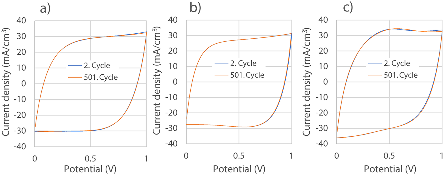
Cycle stability testing was conducted for carbon-doped kaolinitic, illitic, and smectitic clay electrodes in KCl electrolyte over 500 cycles (Fig. 6). KCl was selected as the electrolyte for stability evaluation because it provides a predominantly electric double-layer capacitive response with well-defined and nearly rectangular cyclic voltammograms for all investigated clay types. In addition, the cyclic voltammograms of the smectitic clay electrodes exhibited additional anodic currents, the long-term stability of which was therefore evaluated. Over 500 cycles, the overall area of the cyclic voltammograms showed no pronounced changes, suggesting that the charge-storage response remained broadly stable during repeated cycling.
Cycle stability testing of carbon-doped kaolinitic (a), illitic (b), and smectitic (c) clay with KCl electrolyte at a scan rate of 20 mV s–1.

Figure 6. Long description
From left to right, panel a shows current density in milliampere per cubic centimeter on the y axis and potential in volt on the x axis for kaolinitic clay. Two lines are plotted: blue for 2. Cycle and orange for 501. Cycle. Both lines show a rapid increase in current density from about minus 30 to plus 30 as potential increases from 0 to 1, with minimal difference between cycles. Panel b presents illitic clay with similar axes and trends, where the 2. Cycle and 501. Cycle lines nearly overlap, indicating high cycle stability. Panel c displays smectitic clay, again with overlapping lines for both cycles, showing consistent current density profiles. All panels use the same axis ranges: y axis from minus 40 to plus 40, x axis from 0 to 1. Legends are inside each plot, and the overall trend is that current density profiles remain stable from cycle 2 to cycle 501 for all clay types.
Discussion
Double-layer charge storage effects
The results demonstrated that carbon black-doped clays are capable of storing electrical energy, with a substantial contribution arising from electrical double-layer capacitance at the carbon–electrolyte interface. In the composite electrodes, clay minerals acted as a porous, hydrophilic matrix that supports the dispersion of carbon black and facilitates electrolyte uptake. The large specific surface area and reservoir porosity of clays enhances ion accessibility to electrochemically active surfaces, thereby promoting efficient double-layer formation.
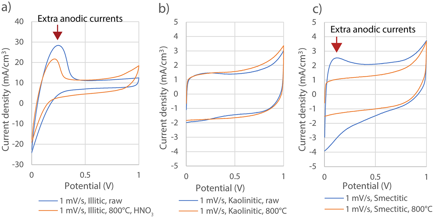
In clay-based electrodes, the strong water adsorption capacity of clay minerals enabled a relatively large liquid-to-clay ratio (~1.5), ensuring good electrolyte penetration throughout the electrode volume. Differences in the rectangular area of cyclic voltammograms among clay types and treatments indicated that the mineralogical composition and structural modification influenced the effective surface area available for double-layer charging. For instance, the largely rectangular cyclic voltammograms of kaolinitic clay–carbon electrodes in KCl electrolyte (Fig. 7b) further indicated that their charge storage was dominated by double-layer processes with limited faradaic contribution.
Cyclic voltammograms of raw and calcined/acidified illitic clay-carbon black supercapacitor with H2SO4 electrolyte (a); raw and calcined kaolinitic clay-carbon black supercapacitor with KCl electrolyte (b); uncalcined and calcined smectitic clay-carbon black supercapacitor with KCl electrolyte (c).
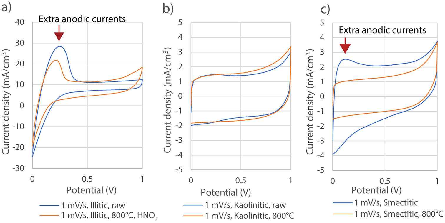
Figure 7. Long description
From left to right, panel a shows current density in milliampere per cubic centimeter versus potential in volts for illitic clay at 1 millivolt per second. The blue line represents raw illitic clay, and the orange line represents illitic clay calcined at 800 degrees Celsius and acidified with H N O sub 3. The orange line shows lower peak current density than the blue, with a red downward arrow and label ‘Extra anodic currents’ above the anodic peak. Panel b shows kaolinitic clay with K C l electrolyte, comparing raw (blue) and calcined at 800 degrees Celsius (orange). Both lines are similar, with the calcined sample showing slightly lower current density. Panel c shows smectitic clay with K C l electrolyte, comparing uncalcined (blue) and calcined at 800 degrees Celsius (orange). The blue line has higher current density, and a red arrow with ‘Extra anodic currents’ is above the anodic region. Legends in each panel specify scan rate and sample type. All panels have x-axes labeled ‘Potential (V)' from 0 to 1 and y-axes labeled ‘Current density (mA/cm super 3)'.
A particularly notable observation is that clay–carbon composite electrodes achieved capacitance values comparable to those of pure carbon black electrodes, despite containing substantially smaller amounts of carbon black. This effect was especially pronounced for uncalcined smectitic clay in KCl electrolyte. This indicated that the electrochemical response of the composites cannot be explained solely by the total carbon mass. Instead, the clay matrix appeared to enhance the utilization efficiency of the conductive carbon phase and, in the case of uncalcined smectitic clay with KCl, to actively contribute to charge storage. Achieving comparable capacitance with significantly reduced carbon content highlights a key advantage of carbon-doped clay electrodes.
Faradaic charge-storage contributions
In addition to double-layer charging, several electrodes exhibited extra anodic currents, suggesting the presence of faradaic charge-storage contributions. In the H2SO4 electrolyte, all electrodes, including pure carbon black electrodes, exhibited pronounced non-rectangular extra anodic currents between ~0 and 0.4 V (Fig. 7a). Because these features were also observed in the absence of clay, they are attributed primarily to carbon-related surface processes rather than to clay–carbon interfacial effects. Such behavior is consistent with reversible redox reactions involving oxygen-containing surface functional groups on carbon, which introduce pseudocapacitive contributions and deviations from ideal double-layer behavior.
In contrast, a distinct additional anodic current in the potential range of ~0.1–0.25 V was observed exclusively for raw smectitic clay–carbon electrodes operated in KCl electrolyte (Fig. 7c). This feature was not present in pure carbon black electrodes with KCl, nor in illitic or kaolinitic clay–carbon composites under the same conditions.
Effects of clay mineralogical structure and treatment
Clay mineralogy and structural modification influenced electrochemical performance significantly. Kaolinitic clay exhibited the greatest volumetric capacitance (5.11 F cm–³ at 1 mV s–1) in combination with H2SO4 electrolyte, while illitic and smectitic clays showed distinct responses depending on treatment and electrolyte conditions.
The XRD analysis of calcined and acid-treated illitic clay revealed weakened diffraction peaks, indicating increased structural disorder and a partial loss of long-range crystallinity. Such structural disorder is likely to enhance surface reactivity and ion accessibility, which is consistent with the relatively pronounced double-layer capacitance observed for the treated illitic clay compared with its raw counterpart (Fig. 7a). However, given the relatively large uncertainty in the specific capacitance values obtained for illitic clay in H₂SO₄ electrolyte, this interpretation should be treated with caution.
Smectitic clay exhibited a more complex behavior. Owing to its expandable 2:1 layered structure and greater cation exchange capacity, raw smectitic clay provides additional sites that may interact with electrolyte ions. These structural characteristics were sensitive to thermal treatment: calcination at 800°C led to dehydroxylation, partial collapse of the layered structure, and a significant reduction in cation exchange capacity. Correspondingly, calcined smectitic clay electrodes showed less capacitance and more ideal double-layer behavior compared with their raw counterparts (Fig. 7c). Analysis by SEM showed that carbon chains, described by Kanbara et al. (Reference Kanbara, Yamamoto, Tokuda and Aoki1987), were clearly visible in calcined and acidified illitic clays and uncalcined smectitic clay (Fig. 3d,e). These chains may account for the increased capacitance observed in these samples with KCl electrolyte.
Electrolyte-specific effects
Electrolyte composition played a decisive role in determining both capacitance magnitude and charge-storage mechanisms. Acidic electrolyte (H₂SO₄) consistently yielded the greatest capacitance across all electrode types, primarily due to its high ionic conductivity and enhanced carbon surface activity. However, the extra anodic currents observed in H₂SO₄ were common to both pure carbon black and clay–carbon electrodes and therefore cannot be attributed to clay-specific effects.
In contrast, the additional anodic current observed for raw smectitic clay–carbon electrodes in KCl electrolyte points to a clay-specific, electrolyte-dependent interaction. Smectite-group minerals are characterized by expandable interlayer regions and exchangeable interlayer cations, which can respond sensitively to the nature of the surrounding electrolyte. In raw smectitic clay, accessible interlayer spaces and exchangeable sites may permit K⁺ ions from the electrolyte to interact with the layered structure, giving rise to additional charge-storage contributions beyond ideal double-layer capacitance. This interpretation is further supported by the observation that smectitic clay–carbon composites in KCl electrolyte achieved capacitance values comparable to those of pure carbon black electrodes, despite containing substantially less carbon. Such behavior underscores the beneficial role of the clay matrix in enhancing charge storage under neutral electrolyte conditions.
This interaction is suppressed after calcination, consistent with the collapse of interlayer spacing and the reduction of cation exchange capacity, which together limit access to interlayer sites. Notably, similar anodic currents were not observed for smectitic clay electrodes in KOH electrolyte. In alkaline environments, pure carbon black electrodes exhibited greater capacitance and more ideal rectangular cyclic voltammograms than the corresponding clay–carbon composites. This difference may be related to the strong hydration and larger effective hydrodynamic radius of OH– ions, which restrict their ability to access confined interlayer environments within smectitic clays. As a result, electrolyte–clay interactions capable of contributing to additional charge storage are diminished under alkaline conditions.
Conclusions
Carbon black-doped clay electrodes exhibited both electrical double-layer capacitance and pseudocapacitance, as evidenced by additional anodic currents observed in the cyclic voltammograms. Clay minerals alone possess insufficient electrical conductivity for application as supercapacitor electrodes, making carbon doping essential. Consequently, a substantial portion of the double-layer capacitance originates from the carbon black; however, for smectitic clays in KCl electrolyte, the additional anodic currents may indicate pseudocapacitive contributions associated with K⁺ intercalation into accessible interlayer spaces. In this study, a relatively modest carbon black content was employed to enhance the relative contribution of the clay minerals and make their effects more discernible. Notably, the smectitic clay–carbon composite in KCl electrolyte contained approximately 1.9 times less carbon black than the pure carbon black reference electrodes, yet exhibited only slightly lower capacitance values. This observation highlights the ability of the clay matrix to efficiently host and utilize conductive carbon networks. While increasing the carbon fraction would probably enhance capacitance, optimization of capacitance was not the primary objective of this work. Instead, the focus was placed on investigating how the clay–carbon–electrolyte system influences the electrochemical response of supercapacitor electrodes.
The comparatively modest capacitance values obtained for the clay–carbon composites (maximum volumetric capacitance of 5.11 F cm⁻³) can be attributed to both the limited carbon content and the relatively large electrode thickness (2.5 mm), which is substantially greater than that typically used in conventional supercapacitor electrodes (<0.5 mm). Greater capacitance could potentially be achieved by increasing carbon content, selecting clays with greater purity, or incorporating redox-active species; however, these approaches were beyond the scope of the present study. Further enhancement of energy density could be achieved by employing electrolytes with wider electrochemical stability windows, enabling operation at greater cell voltages. Excessive carbon loading or the introduction of redox-active additives may negatively affect the economic and environmental advantages of clay-based electrodes. An alternative strategy may involve targeted activation or modification of the clay matrix itself, allowing clay minerals to contribute more actively to charge storage.
Although carbon-doped clays have received limited attention as supercapacitor electrode materials, the results indicate that their charge storage behavior extends beyond ideal electric double-layer capacitance. Clay particles may contribute to additional faradaic or pseudocapacitive processes, potentially increasing total capacitance beyond that provided by carbon alone. While it remains uncertain whether clay particles directly store charge during cycling, their large specific surface area, reservoir porosity, and hydrophilicity make them effective matrices for hosting conductive carbon networks. Calcination and acid treatment can further increase the number of exposed hydroxyl groups and defect sites in illitic clay. Consequently, illitic clay showed enhanced double-layer capacitance following calcination and acid treatment, probably due to the generation of additional surface sites and broken bonds.
Previous studies have focused primarily on clay–metal oxide composites exhibiting redox reactions. Aside from early work by Kanbara et al. (Reference Kanbara, Yamamoto, Tokuda and Aoki1987), electrodes composed solely of clay and carbon black have received little attention. The simplicity of the two-component electrode system used here enabled clearer identification of clay-related effects. Electrodes were prepared using a rapid and straightforward mixing approach involving raw or calcined/acid-treated clays, carbon black, and electrolyte, and were evaluated using a simple test cell design.
Overall, this study demonstrates that carbon black-doped clay composites are capable of storing electrical energy and that the clay mineralogy, processing, and electrolyte composition strongly influence charge storage mechanisms. The ability to achieve comparable capacitance with substantially reduced carbon content underscores the potential of clay-based matrices to develop low-cost, resource-efficient, and sustainable supercapacitor electrodes. Further investigations into ion transport, interfacial charge storage, and long-term stability are required to fully exploit this potential.
Author contribution
Karlis Kukemilks: study conception, sample preparation, and cyclic voltammetry measurements. Jean-Frank Wagner: clay mineralogy and investigation of clay–electrolyte interactions. Jan Philipp Hofmann: interpretation of electrochemical measurements. Oscar Baeza Urrea: clay mineralogical measurements and interpretation, scanning electron microscopy, and interpretation of SEM results. All authors contributed to the writing of the manuscript and the preparation of illustrative materials.
Acknowledgements
The authors acknowledge Yannick Hausener for fabricating components of the measurement cell. The authors also thank Petra Ziegler for preparing the electrolyte solutions, Angela Priebbenow for spelling and grammar corrections, and Dr Harol Anibal Moreno Fernández, Wolfgang Feller, Friedrich Weber, and Christian Schwab for their assistance with the cyclic voltammetry measurements.
Data availability statement
Data will be made available on request.
Financial support
This research was co-funded by the German Federal Environmental Foundation (Deutsche Bundesstiftung Umwelt), grant number 39187/01-23.
Competing interests
The authors declare none.
Use of AI tools
The phrasing, grammar, and clarity of expression of the manuscript’s text were partially improved with artificial intelligence language model (OpenAI’s ChatGPT). All substantive ideas, arguments, and research content are the authors’ own, and the final text was reviewed and edited by the authors.



 Open access

