1. INTRODUCTION
Alignment is the process whereby the orientation of the axes of a Strapdown Inertial Navigation System (SINS) is determined with respect to the reference navigational frame (Chiang et al., Reference Chiang, Huang and Niu2010). It is of vital importance in optimally estimating the attitude, velocity and position for the moving platform (El-Sheimy et al., Reference El-Sheimy, Nassar and Noureldin2004). Poor initial alignment will end up with poor navigation parameter estimation.
Normally, the initial alignment process is divided into two steps – coarse and fine alignment. The purpose of the coarse alignment phase is to estimate the vehicle's heading to the accuracy of a few degrees and roll/pitch to the accuracy of a few tenths of a degree to reduce the linearization errors in the fine alignment phase. Fine alignment is a precise alignment stage during which the small misalignment angles are computed accurately through processing the information from various sensors. Usually, the Kalman Filter (KF) is employed to provide the estimates of attitude and velocity errors in this stage.
Various techniques for coarse alignment have been reported (Schimelevich and Naor, Reference Schimelevich and Naor1996; Jiang, Reference Jiang1998; Savage, Reference Savage2007). These techniques determine the attitude by using the known gravity and Earth's rotation rate in the local level frame and the measurements obtained from accelerometers and gyros (Jiang and Lin, Reference Jiang and Lin1992). However, these techniques cannot be used for underwater vehicles. This is because, when the vehicle is moored or moving, both the accelerometer and gyro measurements will include the values caused by true motions of the vehicle and these values will be treated as system disturbance by the estimator. Considering the projection of the gravity in the inertial frame defines a cone whose main axis is the rotational axis of the Earth, a coarse alignment method using the gravity in the inertial frame as a reference is proposed to correct the effect of wave and manoeuvre motion disturbance (Gu et al., Reference Gu, El-Sheimy, Hassan and Syed2008). This technique is further improved by employing the GPS measurements (GPS velocity and position) to reduce the effects of the linear motion (Silson, Reference Silson2011). The estimation method reported is effective with any initial attitude error. Unfortunately, GPS measurements are unavailable for underwater applications. By improving the coarse alignment model, the technique described in this paper will directly use the body frame velocity provided by the Doppler Velocity Log (DVL) only when the initial position of the vehicle is available.
Most previously reported fine alignment methods establish the SINS error models in the local level reference frame and estimate the attitude and velocity errors by data fusion techniques such as KF, Extended Kalman Filter (EKF) or other nonlinear estimation methods (Setoodeh et al., Reference Setoodeh, Khayatian and Farjah2004; Zhang et al., Reference Zhang, Tian and Jin2004; Han and Wang, Reference Han and Wang2010; Choukroun et al., Reference Choukroun, Weiss, Bar-Itzhack and Oshman2010). In many applications, it is essential to achieve an accurate alignment of SINS within a very short period of time (Wu et al., Reference Wu, Wu, Hu and Hu2011). However, both the coarse and fine alignments need some time to converge. The higher the alignment precision, the longer the alignment time needed. In order to achieve high alignment precision within a short period of time, a backtracking scheme for the alignment is proposed. This scheme is completely different from the traditional two-stage scheme. During the process of the coarse alignment, the parameters that will be used for fine alignment are calculated and recorded. An accurate initial attitude cosine matrix that will be used for the later fine alignment is also calculated in this process. At the end of the coarse alignment, the fine alignment is executed using the data recorded from the coarse alignment. Thus, the fine alignment process takes no extra time. In a sense, the time used for both coarse and fine alignments is extended with this scheme, so the accuracy of the alignments will be improved. In addition, a new model for SINS fine alignment is derived in the inertial reference frame. By using this model, only partial sensor data has to be recorded. So it will be feasible for real time applications.
This paper is organized as follows. In Section 2, the algorithmic principle for the coarse alignment is presented. Section 3 is devoted to the derivation of the SINS error model in the inertial reference frame. Section 4 gives the algorithmic description of the backtracking scheme. Section 5 presents the experimental results. Conclusions are drawn in Section 6.
2. COARSE ALIGNMENT
2.1. Reference frames
The coordinate frames used in this paper are defined as follows:
n-frame: Orthogonal reference frame aligned with North-Up-East (NUE) geodetic axes.
e-frame: Earth-Centred Earth-Fixed (ECEF) orthogonal reference frame.
b-frame: Orthogonal reference frame aligned Inertial Measurement Unit (IMU) axes.
d-frame: Orthogonal reference frame aligned Doppler velocity axes.
i-frame: Earth-Centred Initially Fixed (ECIF) orthogonal reference frame.
n0-frame: n-frame at the start-up. It is rotating with the Earth.
i n0-frame: Orthogonal reference frame non-rotating relative to the i-frame. It's formed by fixing the n-frame at the start-up in the inertial space.
I b0-frame: Orthogonal reference frame non-rotating relative to the i-frame. It's formed by fixing the b-frame at the start-up in the inertial space. $i_{e_0} $-frame: Orthogonal reference frame non-rotating relative to the i-frame. It's formed by fixing the e-frame at the start-up in the inertial space.

2.2 Decomposition of the Attitude Matrix
The attitude matrix, which relates the b-frame to the n-frame, can be decomposed as follows:
 $${\bi C}_b^n = {\bi C}_{n_0} ^n {\bi C}_{i_n _{_0}} ^{n_0} {\bi C}_{i_{b_0}} ^{i_n _{_0}} {\bi C}_b^{i_{b_0}} $$
 The rotation matrix of the b-frame relative to the i b0-frame  ${\bi C}_b^{i_{b_0}} $ can be calculated using the gyro output. At the beginning of the coarse alignment, ${\bi C}_b^{i_{b_0}} $ is identical with:
 $${\bi C}_b^{i_{b_0}} (t_0 ) = {\bi I}_{3 \times 3} $$
where I3 × 3 is a 3 × 3 identity matrix.
Subsequent orientation of ${\bi C}_b^{i_{b_0}} $ is updated by the gyro output  ${\bi \omega} _{ib}^b $:
 $${\bi \dot C}_b^{i_{b_0}} = {\bi C}_b^{i_{b_0}} [{\bi \omega} _{ib}^b \times ]$$
 This means the ${\bi C}_b^{i_{b_0}} $ represents the orientation of the b-frame relative to its initial at start-up, and the i b0-frame axes remain stationary relative to the i-frame. ${\bi C}_{i_n _{_0}} ^{n_0} $ is slowly changing due to the Earth's rotation. It is given by:
 $${\bi C}_{i_n _{_0}} ^{n_0} = {\bi C}_e^{n_0} {\bi C}_{i_{e_0}} ^e {\bi C}_{i_n _{_0}} ^{i_{e_0}} $$
where:
 $${\bi C}_e^{n_0} = \left[ {\matrix{ { - {\rm sin}\;L_0 \;{\rm cos}\;\lambda _0} & { - {\rm sin}\;L_0 \;{\rm sin}\;\lambda _0} & {{\rm cos}\;L_0} \cr {{\rm cos}\;L_0 \;{\rm cos}\;\lambda _0} & {{\rm cos}\;L_0 \;{\rm sin}\;\lambda _0} & {{\rm sin}\;L_0} \cr { - {\rm sin}\;\lambda _0} & {{\rm cos}\;\lambda _0} & 0 \cr}} \right]$$
 $${\bi C}_{i_n _{_0}} ^{i_{e_0}} = ({\bi C}_e^{n_0} )^T $$
 $${\bi C}_{i_{e_0}} ^e = \left[ {\matrix{ {{\rm cos}\;(\omega _{ie} (t - t_0 ))} & {{\rm sin}\;(\omega _{ie} (t - t_0 ))} & 0 \cr { - {\rm sin}\;(\omega _{ie} (t - t_0 ))} & {{\rm cos}\;(\omega _{ie} (t - t_0 ))} & 0 \cr 0 & 0 & 1 \cr}} \right]$$
where L 0 and λ 0 are the geographic latitude and longitude of the initial position. ${\bi C}_{n_0} ^n $ is slowly changing with the movement of the vehicle. It is unknown if the current position is unavailable. In the case of static or moored alignment, ${\bi C}_{n_0} ^n $ is a 3 × 3 identity matrix. During the in-motion alignment, the sailing distance of the vehicle is short, so ${\bi C}_{n_0} ^n $ is also regarded as an identity matrix. Since both the i n0-frame and the i b0-frame are fixed with respect to the i-frame at the start-up, the angular relationship between i n0-frame and i b0-frame ${\bi C}_{i_{b_0}} ^{i_n _{_0}} $ is also fixed. Therefore, ${\bi C}_{i_{b_0}} ^{i_n _{_0}} $ is a constant matrix. If ${\bi C}_{i_{b_0}} ^{i_n _{_0}} $ can be estimated, then the attitude matrix can be obtained by Equation (1).
2.3. Estimation of ${\bi C}_{i_{b_0}} ^{i_n _{_0}} $
In the i b0-frame, there exits:
 $${\bi \dot v}_i^{i_{b_0}} = {\bi C}_b^{i_{b_0}} {\bi f}^b + {\bi C}_{i_n _{_0}} ^{i_{b_0}} {\bi C}_{n_0} ^{i_n _{_0}} {\bi C}_n^{n_0} {\bi g}_m $$
where:
fb is the accelerometer measurement.
gm is the mass attraction force which is the sum of the local gravity and the centripetal force. gm is given by:
 $${\bi g}_m = {\bi g}_l^n + {\bi \omega} _{ie}^n \times [{\bi \omega} _{ie}^n \times {\bi r}]$$
gln is the local level gravitational acceleration expressed in the n-frame, ωien × [ωien×r] is the centripetal force, where:
 $$\openup2pt{\bi g}_l^n = \left[ {\matrix{ 0 \cr { - 9.780318(1 + 5.3024 \times 10^{ - 3} {\rm sin}^2 L - 5.9 \times 10^{ - 6} \; {\rm sin}^2 \; 2L)} \cr 0 \cr}} \right]$$
 $${\bi \omega} _{ie}^n = \left[ {\matrix{ {\omega _{ie} \; {\rm cos}\; L} \cr {\omega _{ie} \; {\rm sin} \;L} \cr 0 \cr}} \right]$$
 $${\bi r} = \left[ {\matrix{ 0 \cr {r_E} \cr 0 \cr}} \right]$$
where:
ωie is the turn rate of the Earth.
r E is the transverse radius of the Earth.
In the i b0-frame, the change in velocity is given by the integral of the  ${\bi \dot v}_i^{i_{b_0}} $:
 $${\bi v}_i^{i_{b_0}} (t) = {\bi v}_i^{i_{b_0}} (t_0 ) + \int_{t_0} ^t {\left({\bi C}_b^{i_{b_0}} {\bi f}^b + {\bi C}_{i_n _{_0}} ^{i_{b_0}} {\bi C}_{n_0} ^{i_n _{_0}} {\bi C}_n^{n_0} {\bi g}_m\right)dt} $$
 The initial velocity  ${\bi v}_i^{i_{b_0}} (t_0 )$ can be obtained by:
 $${\bi v}_i^{i_{b_0}} (t_0 ) = {\bi C}_{i_n _{_0}} ^{i_{b_0}} {\bi v}_r (t_0 ) + {\bi C}_d^b {\bi v}_e^d (t_0 )$$
where:
 $${\bi v}_r (t_0 ) = [\matrix{ 0 & 0 & {\omega _{ie} r_E \cos L_0} \cr} ]^T $$
It is caused by the rotation of the Earth, Cdb is the constant rotation matrix from the Doppler sonar's instrument frame to the b frame, ved(t 0) is the velocity of Doppler at the start-up.
The equivalent change in velocity is given by the Doppler measurement as follows:
 $${\bi v}_i^{i_{b_0}} (t) = {\bi C}_{i_n _{_0}} ^{i_{b_0}} {\bi C}_{n_0} ^{i_n _{_0}} {\bi C}_n^{n_0} {\bi v}_r + {\bi C}_b^{i_{b_0}} {\bi C}_d^b {\bi v}_e^d $$
where:
 $${\bi v}_r = [\matrix{ 0 & 0 & {\omega _{ie} \; r_E \; {\rm cos}\; L} \cr} ]^T $$
Substituting Equation (16) into Equation (13), it yields:
 $$\hskip-9pt\eqalign{& {\bi C}_{i_n _{_0}} ^{i_{b_0}} \left( {{\bi C}_{n_0} ^{i_n _{_0}} {\bi C}_n^{n_0} [\matrix{ 0 & 0 & {\omega _{ie} \; r_E\; {\rm cos}\; L} \cr} ]^T - [\matrix{ 0 & 0 & {\omega _{ie} \; r_E\; {\rm cos}\; L_0} \cr} ]^T - \int_{t_0} ^t {{\bi C}_{n_0} ^{i_n _{_0}} {\bi C}_n^{n_0} {\bi g}_m} dt} \right) \cr &\quad= {\bi C}_d^b {\bi v}_e^d (t_0 ) - {\bi C}_b^{i_{b_0}} {\bi C}_d^b {\bi v}_e^d + \int_{t_0} ^t {{\bi C}_b^{i_{b_0}} {\bi f}^b dt}}\hskip-12pt $$
Define two vectors as follows:
 $$\eqalign{{\bi V}_1 (t) = {\bi C}_{n_0} ^{i_n _{_0}} {\bi C}_n^{n_0} [\matrix{ 0 & 0 & {\omega _{ie} \; r_E\; {\cos} \; L} \cr} ]^T - [\matrix{ 0 & 0 & {\omega _{ie} \; r_E \; {\rm cos}\;L_0 )} \cr} ]^T - \int_{t_0} ^t {{\bi C}_{n_0} ^{i_n _{_0}} {\bi C}_n^{n_0} {\bi g}_m} dt}$$
 $${\bi V}_2 (t) = {\bi C}_d^b {\bi v}_e^d (t_0 ) - {\bi C}_b^{i_{b_0}} {\bi C}_d^b {\bi v}_e^d + \int_{t_0} ^t {{\bi C}_b^{i_{b_0}} {\bi f}^b dt} $$
Then the following equations can be obtained:
 $${\bi V}_2 (t_1 ) = {\bi C}_{i_n _{_0}} ^{i_{b_0}} {\bi V}_1 (t_1 )$$
 $${\bi V}_2 (t_2 ) = {\bi C}_{i_n _{_0}} ^{i_{b_0}} {\bi V}_1 (t_2 )$$
where t 1<t 2.
If the current position is unavailable, the geographic latitude in Equation (19) is set to L 0. From Equations (21) and (22),  ${\bi C}_{i_n _{_0}} ^{i_{b_0}} $ can be calculated by:
 $${\bi C}_{i_n _{_0}} ^{i_{b_0}} = \left[\matrix{ {{\bi V}_2 (t_1 )} & {{\bi V}_2 (t_2 )} & {{\bi V}_2 (t_1 ) \times {\bi V}_2 (t_2 )} \cr} ][\matrix{ {{\bi V}_1 (t_1 )} & {{\bi V}_1 (t_2 )} & {{\bi V}_1 (t_1 ) \times {\bi V}_1 (t_2 )} \cr}\right ]^{ - 1} $$
The accuracy of the coarse alignment is determined by the errors in V1(t) and V2(t). The error source in the coarse alignment includes:
• The error in
$C_n^{n_0} $ caused by position update error of the moving vehicle.• The error in Doppler velocity measurements.
• The error in Doppler installation misalignment matrix Cdb.
• The error in
${\bi C}_b^{i_{b_0}} $ caused by gyro bias.• The error in acceleration measurements caused by motion disturbance.
In the implementation of the coarse alignment, the value of t 1 should be big enough so that the integration process can average these errors over a period of time. Therefore, the effects of the measurements disturbance and the motion disturbance are reduced. In addition, time difference between t 1 and t 2 must be big enough so that ${\bi C}_{i_n _{_0}} ^{n_0} $ changes sufficiently. Otherwise, the estimated matrix would be rank deficient. As a result, t 2 is selected to be the end of the alignment time and t 1 is half of the alignment time in this paper. This estimation method is effective with any initial attitude error, which is similar to the work of Gu et al. (Reference Gu, El-Sheimy, Hassan and Syed2008) and Silson (Reference Silson2011). Besides, as the velocity of Doppler is employed to measure the linear motion, a better attitude estimate will be obtained.
3. FINE ALIGNMENT
The task of the fine alignment is to estimate a more accurate ${\bi C}_{i_n _{_0}} ^{i_{b_0}} $. Then a more accurate attitude cosine matrix Cbn can be obtained by Equation (1). A KF is employed for the fine alignment. In this section, the system and the measurement equations are derived in the ib 0-frame. The advantage of this KF model is that only a little bit of data needs to be recorded for the backtracking scheme. The details of the backtracking algorithm will be presented in Section 4.
3.1. System Equations
The estimated matrix  ${\bi \tilde C}_{i_n _{_0}} ^{i_{b_0}} $ may be written in terms of the true cosine matrix ${\bi C}_{i_n _{_0}} ^{i_{b_0}} $ as follows:
 $${\bi \tilde C}_{i_{n_0}} ^{i_{b_0}} {\rm = [}{\bi I}_{3 \times 3} - {\bi \psi} {\rm ]}{\bi C}_{i_{n_0}} ^{i_{b_0}} $$
where ψ is a skew symmetric matrix composed of the attitude error ϕ, and they are given by:
 $${\bi \psi} {\rm =} \left[ {\matrix{ {\rm 0} & {{\rm -} \gamma} & \beta \cr \gamma & {\rm 0} & {{\rm -} \alpha} \cr { - \beta} & \alpha & {\rm 0} \cr}} \right]$$
 $$\phi = [\matrix{ \alpha & \beta &\gamma \cr} ]^T $$
 As ${\bi C}_{i_n _{_0}} ^{i_{b_0}} $ is a constant matrix, there exists:
 $$\dot \phi {\rm =} 0$$
 Ignoring the influence of the position error, the attitude matrix  $\tilde C_b^n $ which is in error can be described as follows:
 $$\openup3\eqalign{\tilde C_b^n & = {\bi C}_{n_0} ^n {\bi C}_{i_n _{_0}} ^{n_0} {\bi \tilde C}_{i_{b_0}} ^{i_{n_0}} {\bi \tilde C}_b^{i_{b_0}} \cr & \approx {\bi C}_{n_0} ^n {\bi C}_{i_n _{_0}} ^{n_0} {\bi C}_{i_{b_0}} ^{i_{n_0}} [I_{3 \times 3} + {\bi \psi} ][I_{3 \times 3} - {\bi \psi} ^{i_{b_0}} ]{\bi C}_b^{i_{b_0}} \cr & \approx {\bi C}_{n_0} ^n {\bi C}_{i_n _{_0}} ^{n_0} {\bi C}_{i_{b_0}} ^{i_{n_0}} [I_{3 \times 3} + ({\bi \psi} - {\bi \psi} ^{i_{b_0}} )]{\bi C}_b^{i_{b_0}} \cr & = {\bi C}_{n_0} ^n {\bi C}_{i_n _{_0}} ^{n_0} {\bi C}_{i_{b_0}} ^{i_{n_0}} \{ I_{3 \times 3} + [(\phi - \phi ^{i_{b_0}} ) \times ]\} {\bi C}_b^{i_{b_0}}} $$
where  ${\bi \psi} ^{i_{b_0}} $ is a skew symmetric matrix composed of the attitude error $\phi ^{i_{b_0}} $. There exists:
 $${\bi \dot C}_b^{i_{b_0}} = {\bi C}_b^{i_{b_0}} \omega _{ib}^b $$
 And then $\phi ^{i_{b_0}} $ is given by:
 $$\dot \phi ^{i_{b_0}} = - {\bi C}_b^{i_{b_0}} \delta {\bi \omega} _{ib}^b $$
 As can be seen from Equation (28), the attitude error of the fine alignment also includes the error $\phi ^{i_{b_0}} $ which is caused by gyro bias. Therefore, the attitude error equation is given by:
 $$\dot \phi \approx \dot \phi - \dot \phi ^{i_{b_0}} = {\bi C}_b^{i_{b_0}} \delta {\bi \omega} _{ib}^b $$
The estimated velocity may be assumed to propagate in accordance with the following equation in which the estimated quantities are again denoted by a tilde:
 $${\hskip3pt{\dot \tilde }{\hskip-3pt\bi v}_i}}^{i_{b_0}} = {\bi C}_b^{i_{b_0}} {\bi \tilde f}^b + {\bi \tilde C}_{i_n _{_0}} ^{i_{b_0}} {\bi C}_{n_0} ^{i_n _{_0}} {\bi \tilde C}_n^{n_0} {\bi g}_m $$
Ignoring the influence of the position error, it yields:
 $$\hskip3pt{\dot \tilde }{\hskip-3pt\bi v}_i}}^{i_{b_0}} = {\bi C}_b^{i_{b_0}} {\bi \tilde f}^b + {\bi \tilde C}_{i_n _{_0}} ^{i_{b_0}} {\bi C}_{n_0} ^{i_n _{_0}} {\bi C}_n^{n_0} {\bi g}_m $$
Differencing the two Equations (8) and (33), we have:
 $$\eqalign{\delta {\bi \dot v}_i^{i_{b_0}} & = {\hskip3pt{\dot \tilde }{\hskip-3pt\bi v}_i}^{i_{b_0}} - {\bi \dot v}_i^{i_{b_0}} \cr & = {\bi \tilde C}_{i_n _{_0}} ^{i_{b_0}} {\bi C}_{n_0} ^{i_n _{_0}} {\bi C}_n^{n_0} {\bi g}_m - {\bi C}_{i_n _{_0}} ^{i_{b_0}} {\bi C}_{n_0} ^{i_n _{_0}} {\bi C}_n^{n_0} {\bi g}_m + {\bi C}_b^{i_{b_0}} {\bi \tilde f}^b - {\bi C}_b^{i_{b_0}} {\bi f}^b \cr & = {\rm [}I_{3 \times 3} - {\bi \psi} {\rm ]}{\bi C}_{i_{n_0}} ^{i_{b_0}} {\bi C}_{n_0} ^{i_n _{_0}} {\bi C}_n^{n_0} {\bi g}_m - {\bi C}_{i_n _{_0}} ^{i_{b_0}} {\bi C}_{n_0} ^{i_n _{_0}} {\bi C}_n^{n_0} {\bi g}_m + {\bi C}_b^{i_{b_0}} \delta {\bi f}^b \cr & = - {\bi \psi C}_{i_{n_0}} ^{i_{b_0}} {\bi C}_{n_0} ^{i_n _{_0}} {\bi C}_n^{n_0} {\bi g}_m + {\bi C}_b^{i_{b_0}} \delta {\bi f}^b \cr & = \left[({\bi C}_{i_{n_0}} ^{i_{b_0}} {\bi C}_{n_0} ^{i_n _{_0}} {\bi C}_n^{n_0} {\bi g}_m \times )\right]\phi + {\bi C}_b^{i_{b_0}} \delta {\bi f}^b} $$
Equations (31) and (34) may be combined to form a single matrix error equation as follows:
 $$\delta {\bi \dot x} = {\bi F}\delta {\bi x} + {\bi Gw}$$
where:
 $$\delta {\bi x} = \left[ {\matrix{ {\delta v_x^{i_{b_0}}} & {\delta v_y^{i_{b_0}}} & {\delta v_z^{i_{b_0}}} & \alpha & \beta & \gamma \cr}} \right]$$
 $${\bi F} = \left[ {\matrix{ {\matrix{ {0_{3 \times 3}} & {{\bi M}_1} \cr}} \cr {0_{3 \times 6}} \cr}} \right]$$
 $${\bi G} = \left[ {\matrix{ {{\bi C}_b^{i_{b_0}}} & {0_{3 \times 3}} \cr {0_{3 \times 3}} & {{\bi C}_b^{i_{b_0}}} \cr}} \right]$$
 M1 is the skew matrix of  ${\bi C}_{i_{n_0}} ^{i_{b_0}} {\bi C}_{n_0} ^{i_n _{_0}} {\bi C}_n^{n_0} {\bi g}_m $, w represents zero-mean Gaussian white noise which is determined by acceleration bias and gyro bias.
3.2 Measurement Equation
The measurement of the vehicle's velocity in the i b0-frame is given by:
 $${\bi v}_m^{i_{b_0}} = {\bi C}_{i_n _{_0}} ^{i_{b_0}} {\bi C}_{n_0} ^{i_n _{_0}} {\bi C}_n^{n_0} {\bi v}_r + {\bi C}_b^{i_{b_0}} {\bi C}_d^b {\bi v}_e^d $$
Suppose the measurement error is mainly caused by the attitude error, there exits:
 $$\eqalign{{\bi \tilde v}_m^{i_{b_0}} & = {\bi \tilde C}_{i_n _{_0}} ^{i_{b_0}} {\bi C}_{n_0} ^{i_n _{_0}} {\bi C}_n^{n_0} {\bi v}_r + {\bi C}_b^{i_{b_0}} {\bi C}_d^b {\bi v}_e^d \cr & = {\rm [}{\bi I}_{3 \times 3} - {\bi \psi} {\rm ]}{\bi C}_{i_n _{_0}} ^{i_{b_0}} {\bi C}_{n_0} ^{i_n _{_0}} {\bi C}_n^{n_0} {\bi v}_r + {\bi C}_b^{i_{b_0}} {\bi C}_d^b {\bi v}_e^d} $$
Differencing the velocity of SINS and measurements in the i b0-frame. Then the KF measurement model is given by:
 $$\eqalign{{\bi \tilde v}_i^{i_{b_0}} - {\bi \tilde v}_m^{i_{b_0}} & = ({\bi v}_i^{i_{b_0}} + \delta {\bi v}_i^{i_{b_0}} ) - {\rm [}{\bi I}_{3 \times 3} - {\bi \psi} {\rm ]}{\bi C}_{i_n _{_0}} ^{i_{b_0}} {\bi C}_{n_0} ^{i_n _{_0}} {\bi C}_n^{n_0} {\bi v}_r - {\bi C}_b^{i_{b_0}} {\bi C}_d^b {\bi v}_e^d \cr & = \delta {\bi v}_i^{i_{b_0}} + \left[\left( - {\bi C}_{i_n _{_0}} ^{i_{b_0}} {\bi C}_{n_0} ^{i_n _{_0}} {\bi C}_n^{n_0} {\bi v}_r \right)\times \right]\phi} $$
It can be represented by equation:
 $${\bi z} = {\bi \tilde v}_i^{i_{b_0}} - {\bi \tilde v}_m^{i_{b_0}} = {\bi H}\delta {\bi x} + {\bi v}$$
where:
 $${\bi H} = [\matrix{ {{\bi I}_{3 \times 3}} & {{\bi M}_2} \cr} ]$$
 M2 is the skew matrix of  $( - {\bi C}_{i_n _{_0}} ^{i_{b_0}} {\bi C}_{n_0} ^{i_n _{_0}} {\bi C}_n^{n_0} {\bi v}_r )$, v represents zero-mean Gaussian white noise.
4. BACKTRACKING SCHEME
The requirement of SINS initial alignment is to obtain the best accuracy in the shortest time. A backtracking scheme is designed according to this requirement. The traditional and the proposed alignment schemes are shown in Figure 1.
Schemes of the alignment

As can be seen from the traditional scheme, the initial alignment process is divided into two steps – coarse and fine alignment. Each stage occupies a part of the overall alignment time. This conventional approach has its drawbacks; if the coarse alignment occupies too much time or the time for the coarse alignment is not enough, it is hard to guarantee that the misalignments will converge to the required accuracy during the fine alignment. As shown in Figure 1, the advantage of the proposed scheme is obvious. Due to the lengthening span of t 1 and t 2, a more accurate initial attitude will be provided for the fine alignment. As the fine alignment is executed using the former recorded data, it will not take extra time. In addition, compared with the traditional scheme, because the fine alignment runs with the data recorded during the entire process of the alignment, it is equivalent to lengthening the fine alignment time that will make it possible to achieve a higher SINS alignment accuracy.
The traditional SINS fine alignment model in the local level reference frame is not suitable for this backtracking scheme. Because the attitude matrix is corrected by the KF in each filtering circle, all of the IMU measurements have to be recorded for the update of the velocity and the attitude. Due to the high update rate of the IMU, the volume of the measurement data is very huge. But if the new SINS fine alignment model is used, the volume of the recorded data is low enough for the real time applications. As can be seen from the new model derived in Section 3, we only have to record the following variables every 1 second (KF period) to execute the KF and update the navigation parameters.
• The rotation matrix of the b-frame relative to the i b0-frame:
${\bi C}_b^{i_{b_0}} $.• The velocity of Doppler: ved.
• The integral of accelerometer’ measurements in the i b0-frame:
$\int_{t_{k - 1}} ^{t_k} {{\bi C}_b^{i_{b_0}} {\bi f}^b dt} $.

During the fine alignment,  ${\bi C}_n^{n_0} $ is updated by:
 $${\bi C}_n^{n_0} \approx {\bi I} + \left[ {\openup6\matrix{ 0 & {\displaystyle{{r_{\Delta N}^{n_0} \; (t_k )} \over {r_N}}} & {\displaystyle{{r_{\Delta E}^{n_0} \; (t_k )\;{\rm tan} \; L_0} \over {r_N}}} \cr {\displaystyle{{ - r_{\Delta N}^{n_0}\; (t_k )} \over {r_N}}} & 0 & {\displaystyle{{ - r_{\Delta E}^{n_0} \; (t_k )} \over {r_E}}} \cr {\displaystyle{{ - r_{\Delta E}^{n_0} \; (t_k ) \; {\rm tan}\; L_0} \over {r_N}}} & {\displaystyle{{r_{\Delta E}^{n_0}\; (t_k )} \over {r_E}}} & 0 \cr}} \right]$$
where r N is the meridian radius of the Earth, and:
 $$\eqalign{\left[ {\openup3\matrix{ {r_{\Delta N}^{n_0} \; (t_k )} \cr {r_{\Delta E}^{n_0} \; (t_k )} \cr}} \right] & = \left[ {\matrix{ {r_{\Delta N}^{n_0} \; (t_{k - 1} )} \cr {r_{\Delta E}^{n_0} \; (t_{k - 1} )} \cr}} \right] + \left[ {\matrix{ 1 & 0 & 0 \cr 0 & 0 & 1 \cr}} \right]{\bi C}_{i_n _{_0}} ^{n_0} {\bi C}_{i_{b_0}} ^{i_n _{_0}} \int_{t_{k - 1}} ^{t_k} {{\bi C}_b^{i_{b_0}} {\bi C}_d^b {\bi v}_e^d dt} \cr & \approx \left[ {\matrix{ {r_{\Delta N}^{n_0} \; (t_{k - 1} )} \cr {r_{\Delta E}^{n_0} \; (t_{k - 1} )} \cr}} \right] + \left[ {\openup3\matrix{ 1 & 0 & 0 \cr 0 & 0 & 1 \cr}} \right]{\bi C}_{i_n _{_0}} ^{n_0} {\bi C}_{i_{b_0}} ^{i_n _{_0}} {\bi C}_b^{i_{b_0}} {\bi C}_d^b {\bi v}_e^d\; (t_k - t_{k - 1} )} $$
Then the current geographic position Pn is updated by dead reckoning (DR):
 $$\eqalign{{\bi P}^n (t_k ) & = {\bi P}^n (t_{k - 1} ) + \int_{t_{k - 1}} ^{t_k} {{\bi C}_{n_0} ^n {\bi C}_{i_n _{_0}} ^{n_0} {\bi C}_{i_{b_0}} ^{i_n _{_0}} {\bi C}_b^{i_{b_0}} {\bi C}_d^b {\bi v}_e^d} dt \cr & \approx {\bi P}^n (t_{k - 1} ) + {\bi C}_{n_0} ^n {\bi C}_{i_n _{_0}} ^{n_0} {\bi C}_{i_{b_0}} ^{i_n _{_0}} {\bi C}_b^{i_{b_0}} {\bi C}_d^b {\bi v}_e^d (t_k - t_{k - 1} )} $$
The velocity of SINS in the i b0-frame is given by:
 $$\eqalign{{\bi v}_i^{i_{b_0}} (t_k ) & = {\bi v}_i^{i_{b_0}} (t_{k - 1} ) + \int_{t_{k - 1}} ^{t_k} {({\bi C}_b^{i_{b_0}} {\bi f}^b + {\bi C}_{i_n _{_0}} ^{i_{b_0}} {\bi C}_{n_0} ^{i_n _{_0}} {\bi C}_n^{n_0} {\bi g}_m )dt} \cr & \approx {\bi v}_i^{i_{b_0}} (t_{k - 1} ) + {\bi C}_{i_n _{_0}} ^{i_{b_0}} {\bi C}_{n_0} ^{i_n _{_0}} {\bi C}_n^{n_0} {\bi g}_m (t_k - t_{k - 1} ) + \int_{t_{k - 1}} ^{t_k} {{\bi C}_b^{i_{b_0}} {\bi f}^b dt}} $$
The errors on each attitude state are correlated to each other in the coarse alignment model. Therefore, there should be non-diagonal elements in the initial error correlation covariance matrix. But due to the complex error sources in the alignment, it is hard to determine the non-diagonal elements theoretically. So in the implementation of the fine alignment, it is assumed that they are uncorrelated to each other. It is noted that the proposed fine alignment model is completely observable. Therefore, this assumption will not cause a large deviation for real applications. The complete alignment procedure is presented below:
• Step 1. Coarse alignment.
• Step 2. Initialization of the parameters of the KF.
• Step 3. Update
${\bi C}_n^{n_0} $ by Equation (44) and calculate the current geographic position (L, λ) by Equation (46).• Step 4. Update gm by the current geographic position and update the velocity of SINS in the inertial reference frame by Equation (47).
• Step 5. Execute the KF and update
${\bi C}_{i_n _{_0}} ^{i_{b_0}} $, ${\bi v}_i^{i_{b_0}} $ with their corresponding corrections.• Step 6. Goto Step 3 until the fine alignment is finished.
• Step 7. Update the attitude matrix by Equation (1) and output the alignment result.

5. EXPERIMENTAL RESULTS AND DISCUSSION
5.1. Static Alignment Results
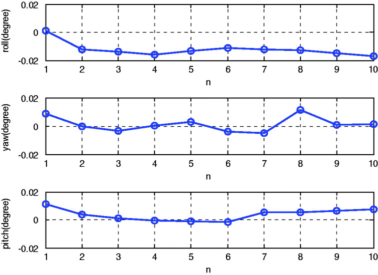
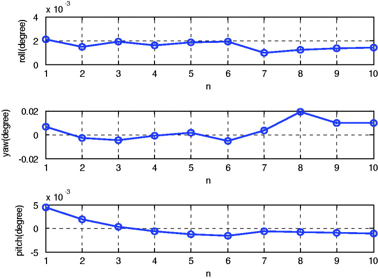
The proposed alignment method was firstly applied to a real static data collected from a navigation grade IMU at latitude 28·2°N. The IMU consists of three ring laser gyroscopes with a drift rate of 0·01°/h(1σ) and three quartz accelerometers with bias of 5 × 10⁻⁵ g(1σ). Its update rate is 200 Hz. During the static test, the average of 10 alignment results calculated by a recently reported technique was regarded as benchmark (Lian et al., Reference Lian, Hu, Wu and Hu2007). Each alignment took 600 seconds (s). The values of t 1 and t 2 in Equation (23) are set to 300 s and 600 s respectively. Figure 2 shows the attitude errors of the coarse alignments and their statistics are listed in Table 1. Figure 3 shows the attitude errors of the fine alignments, while their statistics are listed in Table 2. It can be seen from the Figures and Tables that the accuracy of the alignment is about 0·008° (1σ) in azimuth and about 0·002° (1σ) in levelling in the case of static alignment.
Roll errors (top), Yaw errors (middle), and pitch errors (bottom) of the 10 static coarse alignments

Roll errors (top), Yaw errors (middle), and pitch errors (bottom) of the 10 static fine alignments

Statistics for static coarse alignments.

Statistics for static fine alignments.

5.2. In-Motion Alignment Results
The ship-mounted experimental data were collected to evaluate the performance of the in-motion alignment. The experiment was carried out in Yangzi River. Besides the IMU mentioned in Section 5.1, it was equipped with:
• Bottom-Lock Doppler Velocity Log (DVL). The DVL provided three-axis transformation velocities with accuracy ±5‰ of speed and update rates up to 1 HZ.
• GPS Receiver. The GPS receiver provided velocity with precision of about 0·1 m/s, position with precision of about 10 m, and update rates up to 1 HZ.
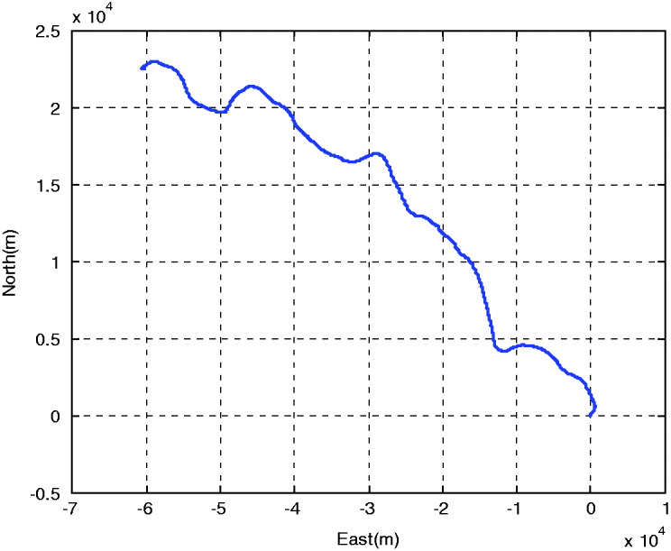
During the experiment, the vessel sailed at the speed of about 4·5 m/s (approximately 4·8 hours). The trajectory of the vessel is shown in Figure 4.
Trajectory of the vessel

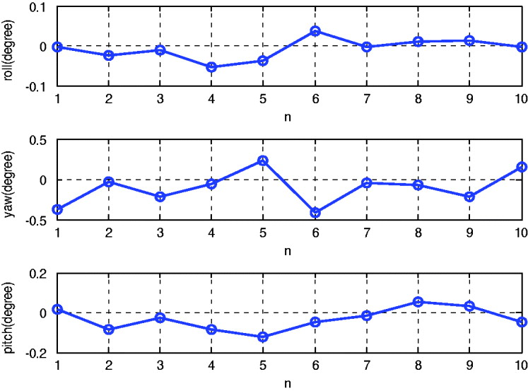
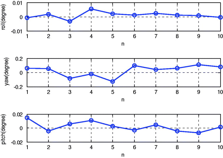
Ten 600-second subsets were extracted to evaluate the performance of the in-motion alignment. Because it is difficult to find another more accurate synchronized benchmark to evaluate the results of the proposed alignment method in the moving environment, the attitude obtained from loosely coupled SINS/GPS integrated navigation was used as reference. Errors of the SINS/GPS integration were estimated and compensated by the 15 states KF. The states include errors of velocity, attitude, position, gyro bias and acceleration bias (Savage, Reference Savage2007). Figure 5 shows the attitude errors of the coarse alignments and their statistics are listed in Table 3. Figure 6 shows the attitude errors of the fine alignments, while their statistics are listed in Table 4.
Roll errors (top), Yaw errors (middle), and pitch errors (bottom) of the 10 in-motion coarse alignments

Roll errors (top), Yaw errors (middle), and pitch errors (bottom) of the 10 in-motion fine alignments

Statistics for in-motion coarse alignments.

Statistics for in-motion fine alignments.

As the results above show, the accuracy for in-motion coarse alignment is about 0·2° (1σ) in azimuth and about 0·05° (1σ) in levelling, which fulfil the need of the fine alignment. In the fine alignment, the attitude errors were reduced further by the KF. The accuracy of the alignment increase to 0·08° (1σ) in azimuth and 0·007° (1σ) in levelling.
5.3. Evaluation of the Proposed Alignment Technique
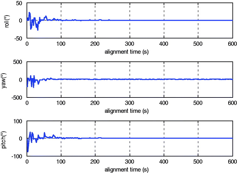
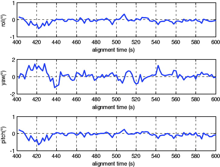
The accuracy of the proposed coarse alignment method is relative to the span between t 1 and t 2. The accuracy is increased if the span is extended. Figure 7 shows the coarse alignment errors with the alignment time. In the implementation of the coarse alignment, the value of t 1 is set to half of the alignment time, while t 1 is the end of the alignment time. It can be seen from Figure 7 that the attitude errors reduce sharply with the increase of the alignment time. Partially enlarged detail of Figure 7 is shown in Figure 8. It is clearly shown that the attitude errors are within a few tenths of a degree if the coarse alignment time is increase to more than 450 seconds.
Roll errors (top), Yaw errors (middle), and pitch errors (bottom) with the alignment time

Roll errors (top), Yaw errors (middle), and pitch errors (bottom) over 400 seconds

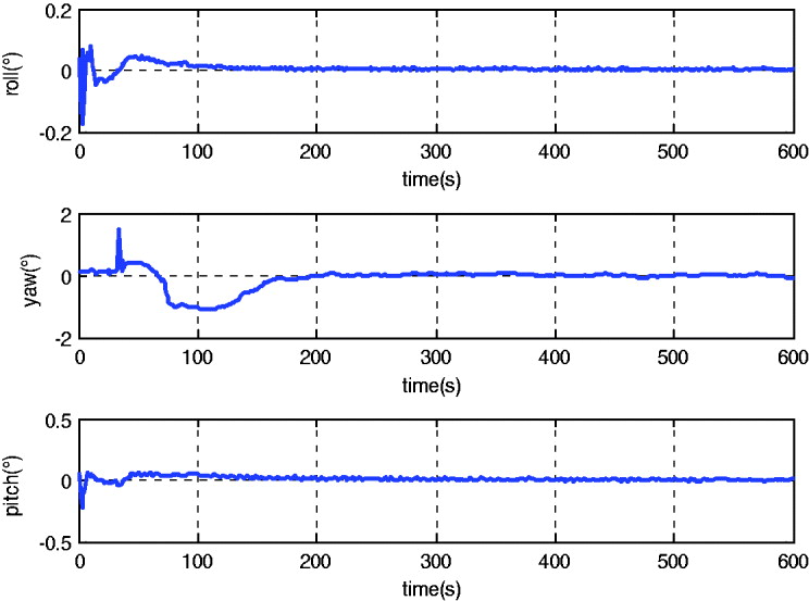
In order to evaluate the performance of the fine alignment, the attitude was calculated by Equation (1) within each KF time update cycle. Compared with the attitude obtained from a high precision reference SINS/GPS integration solution, the error curves of the fine alignment are shown in Figure 9. It can be seen from Figure 9 that the attitude errors converge fast and closely match the attitude provided by the SINS/GPS reference solution.
Roll errors (top), Yaw errors (middle), and pitch errors (bottom) the fine alignment

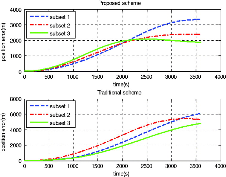
Figure 10 compares the inertial navigation accuracy with the in-motion alignment results obtained from the proposed scheme and the traditional scheme (240 s coarse alignment [Section 2] and 360 s typical DVL-assisted SINS fine alignment [Gao et al., Reference Gao, Zhang, Zhao and Ben2010]). Three subsets were extracted to run the inertial navigation. For the proposed scheme, the maximum position errors of the 1 hour inertial navigation are 3350 m, 2391 m, and 2076 m; while for the traditional scheme, the maximum position errors are 6112 m, 5308 m, and 4800 m respectively. This provides another confirmation of the performance of the proposed fine alignment method.
One hour pure inertial navigation position errors comparison between the proposed (top) and the traditional (bottom) alignment scheme

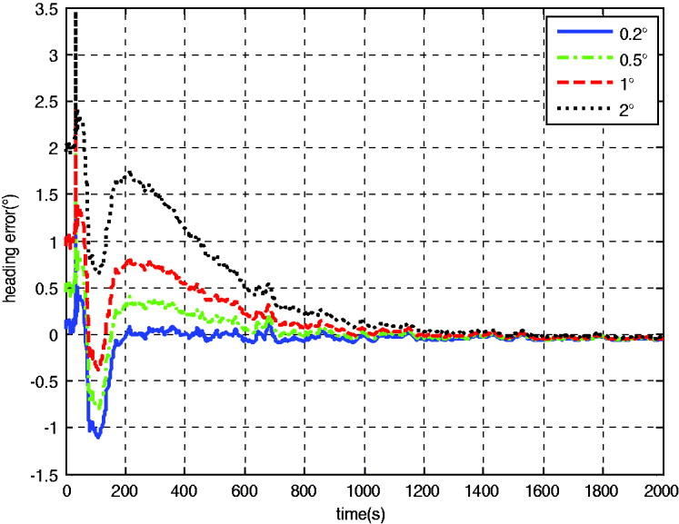
A 2000-second subset was extracted to evaluate the performance of KF model for the fine alignment. Figure 11 shows the error curves of heading with the initial error of about 0·2°, 0·5°, 1° and 2° respectively. It can be seen from Figure 10 that all of the 4 curves have overshoot at the beginning and then converge with time. At the end of the alignment, the 4 curves converge to almost the same value. It is expected that the accuracy of the alignment reaches 0·1° within 600 seconds. It can be seen again that those error curves with larger initial misalignments heading errors took a longer period of time to converge to the value within 0·1°. The initial heading error of 0·5° and 1° took about 600 s and 800 s for it to converge to values smaller than 0·1° respectively. The initial heading error of 2° took even longer. But Figure 5 and Table 3 clearly indicate that the heading errors of the coarse alignments are less than 0·5° and hence fulfil the requirement of the fine alignment.
Error curves of heading with different initial misalignments

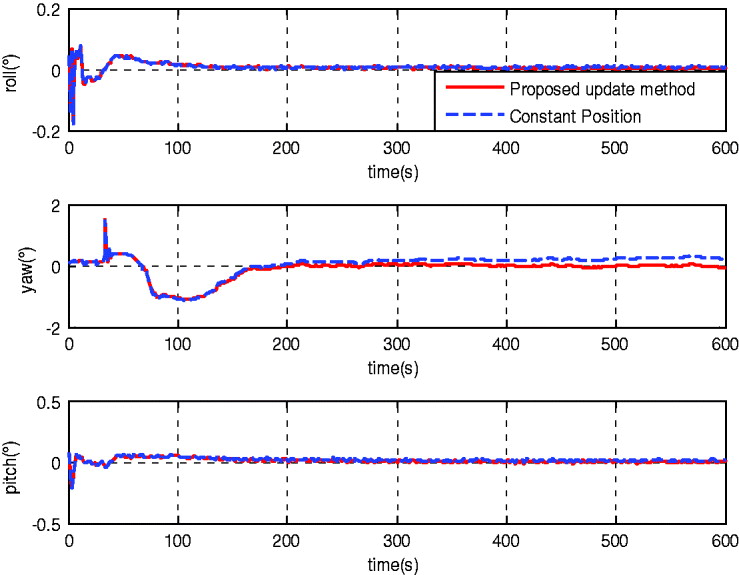
Figure 12 compares the attitude error with different position update methods. As can be seen from Figure 12, the position error plays an important part in the performance of the fine alignment. If a constant position is used (${\bi C}_n^{n_0}$ = I), the error in ${\bi C}_n^{n_0} $ will become larger with the increase of time. This error will directly be added into the attitude error by Equation (1). In addition, since the value of  $C_n^{n_0} $ is used in the fine alignment model, the performance of the KF will also be decreased. It is clearly shown in Figure 12 that it will lead to the biased estimation of the attitude error. The final heading error with the proposed position update method [Equations (44)–(46)] is −0·058° while it is 0·235° by using the constant $C_n^{n_0} $. In addition, if the position measurement is still unavailable after the alignment, the resulting position can be used as the current position.
Effects of the position error in the fine alignment

6. CONCLUDING REMARKS
In this paper, a novel SINS initial alignment scheme has been developed for underwater vehicles. Based on this framework, the following novel work has been completed:
• An improvement of the current coarse alignment methods has been made by employing the velocity of Doppler to correct the effect of the linear motion.
• A backtracking scheme is proposed. It is equivalent to lengthening the time of both coarse and fine alignment. Therefore, the accuracy for both coarse and fine alignment is improved.
• Sensor data has to be recorded during the process of the coarse alignment with the backtracking scheme. A new SINS fine alignment model is derived in the inertial reference frame. With this new model, the volume of the recorded data is very low and hence it is useful for real time applications.
Experimental results have demonstrated that this novel scheme is effective in SINS alignment problem and reaches the accuracy of about 0·008° (1σ) in azimuth and 0·002° (1σ) in levelling in the case of 600-second static alignment, while the accuracy of the 600-second in-motion alignment is about 0·08°(1σ) in azimuth and 0·007° (1σ) in levelling.
The technique proposed in this paper takes no account of sensor errors which limit the alignment accuracy. So this method is not suitable for low cost IMUs. Adjustment of the proposed method for use with low cost IMU is a topic for further investigation.
ACKNOWLEDGEMENTS
The first author is sponsored by the China Scholarship Council for his PhD studies at the University of New South Wales, Sydney, Australia. This work was supported in part by Program for New Century Excellent Talents in University (NCET) of P. R. China.