

Introduction
Mass loss of the Greenland ice sheet (GrIS) is rapid and accelerating, caused by increased surface melt and acceleration of outlet glaciers (Reference Rignot and KanagaratnamRignot and Kanagaratnam, 2006; Van den Reference Van den BroekeBroeke and others, 2009; Reference HannaHanna and others, 2013; Reference NickNick and others, 2013). The land-terminating marginal zone of the ice sheet exhibits seasonal and episodic velocity variations, driven by routing water from the surface to the bed (Reference Zwally, Abdalati, Herring, Larson, Saba and SteffenZwally and others, 2002; Reference Joughin, Das, King, Smith, Howat and MoonJoughin and others, 2008; Reference Van de WalVan de Wal and others, 2008; Reference Bartholomew, Nienow, Mair, Hubbard, King and SoleBartholomew and others, 2010; Reference Hoffman, Catania, Neumann, Andrews and RumrillHoffman and others, 2011). The degree to which basal motion is altered due to a given meltwater input is difficult to determine from surface measurements alone. Surface velocities are easily measured with GPS (e.g. Reference Hoffman, Catania, Neumann, Andrews and RumrillHoffman and others, 2011) and from repeat satellite imagery (e.g. Reference Joughin, Smith, Howat, Scambos and MoonJoughin and others, 2010), but partitioning estimates between ice deformation and basal motion are based on an idealized theory of ice flow, impacting estimates of mass flux. Gravity-driven ice flow is assumed to be laminar, with highest velocity at the surface, decreasing velocity with depth and sliding motion over the base. Internal ice deformation is controlled by the stress state and ice rheology, and depends strongly on temperature, grain texture and other factors that are unknown, except for locations where limited observations exist (near the slowly moving ice divide; Reference Dahl-Jensen, Thorsteinsson, Alley and ShojiDahl-Jensen and others, 1997; Reference ThorsteinssonThorsteinsson, 2002). Knowledge of the rheology of glacier ice and the mechanics of basal motion is key to understanding and correctly modeling the behavior and future evolution of the GrIS.
Here we present a unique set of ice deformation measurements from two drill sites located in the marginal zone of the ablation area of the western GrIS. Borehole deformation measurements allow us to directly quantify the contribution of ice deformation, and thus the contribution of basal motion, to surface speed. Using a two-dimensional (2-D) (plane strain) finite-element ice-flow model we investigate how basal topography and stress transfer affect ice deformation. From the ice deformation measurements and model experiments, the ice rheological parameters are determined and the importance of longitudinal stress transfer is assessed.
Field Sites
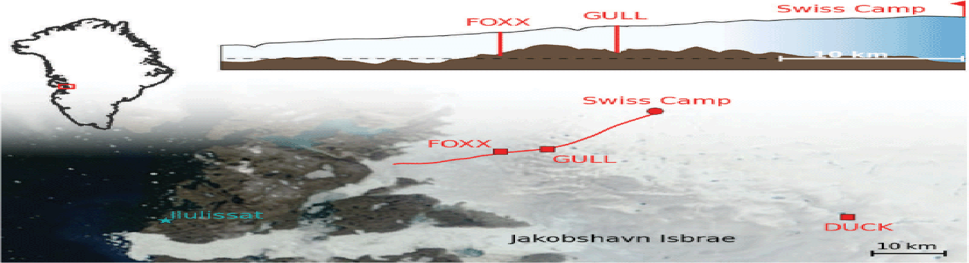
The field sites are located in the West Greenland ablation area on an approximate flowline downstream of Swiss Camp (69˚33.147̍ N, 49˚19.848’ W; 1093 m a.s.l.). The sites are outside the dynamic influence of fast-flowing Jakobshavn Isbræ located 30 km to the south (Reference Lüthi, Funk and IkenLüthi and others, 2003) and are representative of the slower-moving marginal area. Two drill sites, FOXX (69826.7550 N, 49853.1070 W; 700 m a.s.l.) and GULL (69˚27.1410 N, 49˚43.0930 W; 880 m a.s.l.), at distances of 30 and 20 km from Swiss Camp, respectively (Fig. 1), move at ~100 m a-1. Measured ablation rates in 2011 and 2012 were 6 m a 1 at FOXX and 4.5 m a-1 at GULL.
The study site indicated by a red area within the Greenland coastline is illustrated with a Moderate Resolution Imaging Spectroradiometer (MODIS) satellite image (NASA Goddard Space Flight Center, 2010). The drill sites FOXX and GULL are located on a flowline downstream of Swiss Camp, and the 1995 drill site DUCK is located near Jakobshavn Isbræ (Reference Lüthi, Funk, Iken, Gogineni and TrufferLüthi and others, 2002). The red flowline was determined from velocity data of Reference Joughin, Smith, Howat, Scambos and MoonJoughin and others (2010). The inset shows bed and surface topography along the flowline at fivefold vertical exaggeration (data from DTU Space, 2005; Reference GogineniGogineni, 2012; no data close to the margin). The dashed horizontal line indicates sea level.
A total of 13 holes reaching the glacier bed were drilled at FOXX and GULL in summer 2011,using standard hot-water drilling equipment (Reference Iken, Echelmeyer, Harrison, Rado and BeaudoingIken and others, 1989). A hot-water jet of 808C at 80 bar was used to melt the holes at a prescribed speed with an electric winch (Reference Humphrey and EchelmeyerHumphrey and Echelmeyer, 1990). Seven holes ~620 m deep were drilled to the bed at FOXX and six ~700 m holes were drilled to the bed at GULL.
Instrumentation
At each drill site two boreholes, spaced 30 m (FOXX) and 40 m (GULL) apart, were instrumented with the digital borehole sensor system DIBOSS (Appendix A), which consists of several multi-sensor units. Each unit has a digital pressure sensor, a temperature sensor, a two-axis tilt sensor and a three-axis magnetometer. The multi-sensor units were connected by cables that can accommodate 20% of total strain before failure. Sensor spacing decreased towards the bed, where high deformation rates were expected. Thermistor strings to measure near-surface temperature were deployed in the same holes. The two boreholes at FOXX were equipped with seismometers, complementing a dense surface seismology network (Reference RöösliRöösli and others, 2014; Reference Walter, Chaput and LüthiWalter and others, 2014). On the surface, a differential GPS system (see next section) and an automatic weather station were installed at each drill site.
Several down-hole measurements were performed immediately after drilling at each site: logging with an optical televiewer, electrical d.c. conductivity of the ice between boreholes, and pump tests to probe the hydraulic response of the subglacial drainage system.
Data and Methods
Details of the methods used to determine the tilt-sensor data and the resulting ice deformation profiles are given in the subsections below. Complementary data used in the analysis are described here.
Ice temperature was measured with the DIBOSS system and with additional thermistors closer to the surface. Thermistor strings consisted of multi-core cables with negative temperature coefficient thermistors (Fenwal 135–103FAG-J01), for which individual calibration curves were determined in a calibration bath at six to eight reference temperatures. The absolute accuracy of measured temperatures is better than 60 mK. In the field, resistances were measured with a full bridge circuit logged by a Campbell CR-1000 data logger, and occasional readings were made with a digital multi-meter.
Cross-borehole conductivity (CBC) was measured with the aim of detecting layers with high conductivity (e.g. the Holocene–Wisconsin transition). The method was the same as that used by Reference Lüthi, Funk, Iken, Gogineni and TrufferLüthi and others (2002). A bare wire installed in one hole served as a fixed line electrode. A second electrode was attached to an insulated wire that was lowered in a second borehole. Depth and velocity were controlled using the drill winch and its logging. A d.c. voltage of 20–40 V was applied between the electrodes, and the resulting current through the ice was measured with a high-precision ammeter and registered with a data logger at a sampling interval of 1 s. With a constant velocity of 600 m h 1 continuous logs of the current in intervals of ~17 cm were obtained. At GULL, the fixed-line electrode did not reach the bed and we only have conductivity values down to 610 m.
Two ice thickness datasets from airborne ice radar (DTU Space, 2005; Reference GogineniGogineni, 2012) were used to generate an interpolated grid dataset using the natural neighbor interpolation based on Delaunay triangulation. The bed elevation and the ice thickness data are shown in Figure 2. The flightlines of DTU Space (2005) are in an east–west direction with an along-track sample spacing of 28 m and north–south spacing of 1–1.5 km. For both drill sites there is a flightline within 100 m but at a slight angle to the flowline. Ice thicknesses determined from radar data and drilling agree well at GULL (<20 m difference); at FOXX the discrepancy is higher (~50 m difference). A flowline from Swiss Camp through the drill sites was calculated using satellite-derived gridded velocities (data from Reference Joughin, Smith, Howat, Scambos and MoonJoughin and others, 2010). The surface and bed topography determined from the radar data along this flowline are shown in the inset of Figure 1.
(a) Bed elevation in the area of the drill sites. The flowline (red) downstream of Swiss Camp was calculated from velocity data (Reference Joughin, Smith, Howat, Scambos and MoonJoughin and others, 2010). (b) Ice thicknesses in the area of the drill sites. Data from DTU Space (2005) and Reference GogineniGogineni (2012).

GPS antennas were mounted at FOXX and GULL on poles drilled into the ice. GPS data were logged every 15 s, and positions were determined by carrier-phase differential processing using TRACK software (Reference ChenChen, 1998) with the base station QING (16 km northwest of FOXX and 19 km northwest of GULL) as a reference, and final International GNSS (global navigation satellite systems) Service satellite orbits. Each 15 s GPS time series was resampled to a 15 min interval, and a 3 hour moving average was then applied to reduce the sidereal noise (Reference Hoffman, Catania, Neumann, Andrews and RumrillHoffman and others, 2011).
Determination of velocity gradients from tilt sensor measurements
Tilt sensor data were used to infer vertical gradients of horizontal velocity throughout the ice column in two boreholes at each of the drill sites FOXX and GULL. Sensor tilt angle variations cannot be directly inverted to determine all nine independent components of the velocity gradient tensor, Lij = ∂ui/ ∂xj Tilt angles were analyzed with two approximate methods, both relying on simplifying assumptions on ice flow. For the fitting procedure described below, tilt angle data from the winter period (October 2011–May 2012) were used when short-term variations of surface velocity and tilt angle were negligible (Appendix B).
Method A uses an analytic solution for the time evolution of the zenith angle by neglecting the transversal velocity component (v = 0; Eqns (15) and (16) of Reference Keller and BlatterKeller and Blatter, 2012). Components Lxz (vertical shear) and Lzz (vertical extension) of the velocity gradient tensor are determined by fitting the analytical expression to measured zenith angles.
Method B assumes zero vertical extension (L zz = 0), such that tilt angle variations are solely due to vertical shearing (L xz, L yz ≠ 0). The projection of a tilt sensor with initial angle θ0 onto a plane in vertical distance ∆z is x 0 = ∆z tan θ 0, and x 1 = ∆z tan θ1 at a later time t 1 = t 0 + ∆t. The velocity gradient is therefore
and analogously for the y –direction. The trace of projected sensor locations on the map plane is rotated into the flow direction. Tilt angles along and across the flowline are thus directly determined.
The analysis using method B shows negligible sideways movement of the tilt sensors during winter (which would correspond to lateral spreading), whereas a small sideways rotation is observable in summer. This justifies the assumption of planar flow for method A during winter. Conversely, the vertical stretching rate, Lzz , determined with method A, shows alternating signs, and setting vertical stretching to zero only marginally affects the results of the fitting procedure. Therefore setting Lzz = 0 in method B only introduces a small error. Further effects of three-dimensional (3-D) flow cannot be assessed with the fitting procedures, such as transverse stress fields leading to out-of-plane deformation. Compared with vertical shearing, Lxz , these effects are likely small in the lower half of the ice column where most of the tilt sensors are located, but might be important close to the base.
Deformation rates Lxz determined with both methods are summarized in Tables 2 and 3 (Appendix C). The difference between the two approaches is <10% for sensors in the cold ice (except for values <0.02 a-1 at FOXX and <0.04 a-1 at GULL). For the sensors in the basal temperate ice layer the approaches differ by 30%, since the two lowest sensors of each string could not be satisfactorily fitted with method A. This might be a consequence of the temperate ice, which precludes freezing of the sensor to the ice, or an effect of local bed topography.
Theoretical velocity gradients
Theoretical vertical gradients of horizontal velocity L th xz were calculated for a gravity-driven, parallel-sided slab of ice at inclination angle α, using Glen’s flow law (e.g. Reference Cuffey and PatersonCuffey and Paterson, 2010)
with ice density p, gravitational acceleration g, and depth below the surface h. A power-law exponent n = 3 is conventionally assumed. A is a temperature-dependent rate factor and α the surface slope (details below). Horizontal stress transfer is not accounted for in this equation.
Published values of the recommended ice flow law rate factor A at different temperatures show a considerable spread (Reference PatersonPaterson, 1994; Reference Cuffey and PatersonCuffey and Paterson, 2010). The older values from Paterson (1994) agree well with the temperature dependence found by Reference Smith and MorlandSmith and Morland (1981). Current values recommended by Reference Cuffey and PatersonCuffey and Paterson (2010) are much lower and exhibit a different temperature dependence. Both series of values were used in this study, and are referred to as A Paterson and A Cuffey.
Surface slopes α at FOXX and GULL were determined from surface elevations sampled during radar flights (DTU Space, 2005; Reference GogineniGogineni, 2012). These data were filtered with a triangular function with an averaging length of 4l, assuming a stress coupling length l of 4–10 times the ice thickness (Reference Kamb and EchelmeyerKamb and Echelmeyer, 1986). Resulting surface slopes for FOXX and GULL are αFOXX = 1. 67 ± 0. 2˚ and αGULL = 1. 30 ± 0. 2˚.
Determination of basal motion
Displacements measured at the ice surface are the sum of ice deformation and motion over the glacier bed. Using surface displacements from GPS and tilt sensor data from the period October 2011–May 2012, basal motion was determined by subtracting from surface GPS displacements the vertical integral of Lxz –values measured at individual sensors. The approaches used to interpolate sparse data points included linear interpolation of values, and constant values in depth intervals centered about the sensors. Both approaches yielded similar results; the difference of the vertical integral was 0.04 m a-1 for FOXX and 0.2 m a-1 for GULL.
Flow model implementation
We use a 2-D flowline model (FS model; Reference LüthiLüthi, 2009) to explore how variations of basal conditions and geometrical chang ges in bed topography affect ice deformation. The flow model solves the Stokes equations with power-law rheology with the finite-element (FE) method in 2-D (plane strain), and implements free-surface flow with vertical adjustment of surface geometry. This model was implemented with the Libmesh FE library (Reference Kirk, Peterson, Stogner and CareyKirk and others, 2006). The equations for conservation of mass and linear momentum are (using the summation convention)
where v = ( u, v, w) is the velocity vector, σ ij is the Cauchy stress tensor, ρ is ice density and gi is gravity. Glen’s flow law (e.g. Reference Cuffey and PatersonCuffey and Paterson, 2010) is used as the constitutive equation for the stress-dependent ice viscosity
with σ(d) ij the deviatoric stress tensor, T = (1/2 σ(d) ij σ(d) ij)1/2 the effective shear stress, n the power-law index, and A a temperature-dependent rate factor. In the model, A was set per element, according to the mean measured ice temperature with the values recommended by Reference Cuffey and PatersonCuffey and Paterson (2010) or Paterson (1999).
The model domain was discretized with second-order QUAD9 elements with Galerkin weighting. Model variables were (u, w, p) with a second-order approximation for the velocities and a first-order approximation for the pressure (forming a LBB-stable set). The domain of 5000m length and 600 or 700m thickness was uniformly meshed with 150 ˟ 30 elements, and nodes corresponding to the base were mapped to the bed topography. To implement sliding processes, a basal slipperiness C was used as the ratio between velocity at the basal boundary of the ice u b and basal shear stress T b (e.g. Reference Gudmundsson and RaymondGudmundsson and Raymond, 2008)
This boundary condition was implemented as a layer of constant viscosity (linear rheology) with thickness h s = 10m and discretized with two elements in the vertical, and the same spacing in the horizontal. Viscosity of this layer was set to spatially varying values, representing areas with different slipperiness C. Dirichlet boundary conditions on the velocities (u b,w b) = (0, 0) were applied at the bottom of the constant-viscosity layer, and periodic boundary conditions on the velocities were set at the upstream and downstream (left and right) boundaries.
The model surface geometry was evolved with time until a stationary geometry was reached. For each time step, ∆t, the surface node coordinates were moved in the vertical by
where z s are nodal surface coordinates, with (u s, w s) the corresponding nodal surface velocity vector (in 2-D).
Results and Discussion
Measured ice deformation
Borehole tilt data were used to infer vertical gradients of horizontal velocity, which is the dominant component of gravity-driven ice-sheet flow. By restricting our analysis to the period October 2011–May 2012, when surface velocities were stable (Fig. 4), we determine that ice deformation integrated over depth contributes 21 and 40 m a-1 to the surface velocities of 72 and 76 m a-1 at FOXX and GULL, respectively (Fig. 3; Table 1).
Depth profiles of ice temperature, conductivity, deformation and velocity measured at FOXX and GULL. Dots in (a) and (d) indicate depths of temperature sensors, and green and purple curves show the CBC measurements (arbitrary units). Red symbols in (b) and (e) show vertical gradients of horizontal velocity from tilt sensors (dots and triangles for independent boreholes). Red curves in (c) and (f) show horizontal velocity, integrated from the velocity gradients. Subtraction of deformational velocity u d (red arrow) from measured surface velocity u s (blue arrow) leads to inferred basal motion u b (black arrow). Theoretical ice deformation rates are indicated by colored areas in (b) and (e) (for a range of surface slopes), and with two sets of temperature-dependent flow law parameters (green: Reference PatersonPaterson, 1994; cyan: Reference Cuffey and PatersonCuffey and Paterson, 2010). The corresponding velocity profiles are shown in (c) and (f). The depths of the cold–temperate transition surface (CTS) and the Holocene–Wisconsin transition (HWT) are indicated. Black horizontal lines indicate the depths where the glacier bed was encountered while drilling (differs up to 10 m for string1 and string2 at FOXX).

Daily mean values of surface, deformational and basal velocities measured at (a) FOXX and (b) GULL. Ice deformation in (b) ends before March 2012 because of failure of the lowermost sensors. GPS-derived surface velocity is shown with the blue line, and contributions from ice deformation and basal motion are represented by the widths of the red and blue areas. (c) Relative contribution of basal motion to surface velocity.

Evaluation of basal motion contribution to measured surface velocity at three drill sites. Mean winter surface velocities u s, velocity due to ice deformation u d, amount of basal motion u 0 = u s – u d, and percentage of basal motion.

Accordingly, basal motion contributes 73% and 44% to the observed surface velocity during winter. Earlier measurements at a nearby site, DUCK (Fig. 1), at the margin of Jakobshavn Isbræ revealed basal motion of 63% of total ice velocity (Reference Lüthi, Funk, Iken, Gogineni and TrufferLüthi and others, 2002; Table 1). The ice deformation values determined are barely affected by the choice of interpolation method (see previous section). Relative uncertainty of Lxz for the highest and lowest sensors reaches ~10% in the cold ice, and 30% in the temperate ice layer. We can exclude intermediate layers with very high deformation rates, which would lead to cable rupture, such as that observed close to the bed at GULL (see next paragraph). Thus we assume that observed tilt angle variations are representative of the respective depth intervals. These values for u d should be considered a lower bound, since somewhat higher values of Lxz between sensors are possible. Assuming a soft layer at FOXX, similar to that measured at GULL (below 600 m in Fig. 3e), but with a maximum value for Lxz compliant with an intact cable (the cables connecting the sensors can sustain a maximum strain of 20%, which gives a strain limit of 0.47), the velocity due to ice deformation u d rises to 24.6 m a –1 and therefore basal motion u b will decrease to 51.8 m a-1 or 68%. A bottom layer of very high ice deformation can be excluded as the cable of string2 reaches the bed and stayed intact throughout the two years. The values in Table 1 are therefore an upper bound for the basal motion but do not change the general pattern of ice deformation profiles.
Figure 3b and e show important differences between measured ice deformation rates and theoretical values L th xz . Both measured deformation profiles show a zone of increased deformation rates at ~500 m depth and a reduction at greater depths, more so at GULL than at FOXX. Deformation rates in the lowest part of FOXX (Fig. 3b) are three times smaller than expected from theory. At GULL (Fig. 3e), deformation rates close to the base are highly variable, and two sensors between 600 and 650 m depth show high deformation rates. Sensors below this zone failed after 219 and 248 days, presumably due to cable rupture after overstretching. These enhanced deformation rates might be due to ‘soft’ ice from the late Wisconsin observed in several deep ice cores (Reference Dahl-Jensen and GundestrupDahl-Jensen and Gundestrup, 1987; Reference PatersonPaterson, 1991; Reference Dahl-Jensen, Thorsteinsson, Alley and ShojiDahl-Jensen and others, 1997).
At GULL the depth range of strongly increased deformation rates between 595.0 m (Lxz = 0. 086 a 1) and 622.0 m (Lxz = 0.291 a-1) coincides with increasing ice conductivity between 600 and 610 m depth (CBC; Fig. 3d). Unfortunately, no conductivity measurements could be made below 610 m. This layer of increasing conductivity is at a depth of ~ 85% of the ice thickness. At DUCK the Holocene–Wisconsin transition (HWT) is located at 82% of the ice thickness and also coincides with increasing CBC values (Reference Lüthi, Funk, Iken, Gogineni and TrufferLüthi and others, 2002). Tracing the HWT in ice radar data, Reference Karlsson, Dahl-Jensen, Gogineni and PadenKarlsson and others (2013) found relative depths between 80% and 85% at the ice-sheet margins near the study site. Transferring these values to FOXX, we would expect the HWT at ~527 m, which agrees with a strong increase in CBC current at 525 m depth (Fig. 3a). No tilt sensors were installed at this depth, and increased deformation of soft ice-age ice, if present at FOXX, was not recorded.
To investigate seasonal changes of basal motion, the contribution of ice deformation (evaluated with method B) and basal motion to observed surface velocity over the course of 1 year is shown in Figure 4. Daily mean surface velocities from GPS are nearly constant throughout winter, with a more than twofold episodic speed-up during the summer melt season. Ice deformation rates remain approximately constant throughout the year, with marked oscillations coincident with surface speed-up and diurnal variations. A detailed analysis of short-term velocity variations is presented in a separate manuscript (Ryser and others, unpublished information). The relative contribution of basal motion exceeds 90% during periods of intense surface melting with high flow velocities.
Flow model experimentsec
The theoretical velocity gradients L th xz assume no horizontal stress transfer. By contrast, velocity gradients determined from measurements show near-constant (FOXX) or highly variable (GULL) values in the lower parts of the ice column. The observed deformation profiles may be explained by several processes: (1) inhomogeneous stress transfer to the bed due to sticky and slippery patches; (2) stress redistribution due to basal topography; or (3) vertically varying rheology (soft and stiff ice layers).
The model geometry was inspired by the observed surface and bed topography. The bed geometry (Fig. 1 inset, based on ice radar (DTU Space, 2005; Reference GogineniGogineni, 2012)) exhibits a ~5–10 km length scale of hills and depressions, and shows that FOXX is located on a down-sloping flank while GULL is located over a basal depression. We therefore chose a model length of 5 km (with periodic boundaries) and flat bedrock, hills and depressions of the scale of features in the radar data. Although the exposed bedrock at the ice-sheet margin has substantial smaller-scale topography (e.g. narrow canyons), such features cannot be detected with radar, and it is unlikely that ice would slide through such small-scale obstacles at tens of meters per year.
A wide variety of flow model experiments were performed to understand the main features of the measured borehole deformation patterns. First, the effect of sticky and slippery patches on the ice deformation was tested. Then the influence of the bed topography was investigated. To test the influence of ice rheology, model runs using A Paterson or A Cuffey were performed. Unreasonably high deformation rates (compared with measurements) or too low surface velocities were found using A Paterson, such that all the results presented here use the rate factors of Reference Cuffey and PatersonCuffey and Paterson (2010) for the measured temperatures at the respective depths.
Results from a small selection of these model runs are shown in Figure 5. In a set of model runs on inclined, flat bed geometries the spatial extent of a slippery patch and its slipperiness C was varied to assess its influence on the ice deformation profiles at several positions. Figure 5a and b are examples for varying stress transfer due to slippery patches, with deformation gradients Lxz evaluated at a series of virtual boreholes. On the slippery patch, ice deformation in the lower part of the ice column is much smaller than on the sticky patch. This reduction in the lower part agrees well with the general pattern of ice deformation measurements from FOXX. The spatial extent of the slippery patch mainly influences the maximum amount of basal motion and the surface velocity on the entire model domain. Further, if the slippery patch is small compared with the sticky patch (e.g. Fig. 5a), ice deformation is largest somewhat above the glacier bed, whereas ice deformation rates are small on a longer slippery patch, but increase continuously towards the bed.
Results from flow model experiments with basal patches of different slipperiness and various bed geometries. Insets show vertical sections of the 2-D model geometries. Patches with high/low slipperiness are indicated with green/gray horizontal bars. Modeled velocities at surface u s and base u b are given at different locations. Colored vertical lines indicate virtual boreholes where ice deformation rates, Lxz = du= dz, were evaluated which are shown in the main panel with the same colors. Red symbols (dots/triangles for string1/2) indicate measured deformation rates at (a–c) FOXX and (d–f) GULL for comparison.
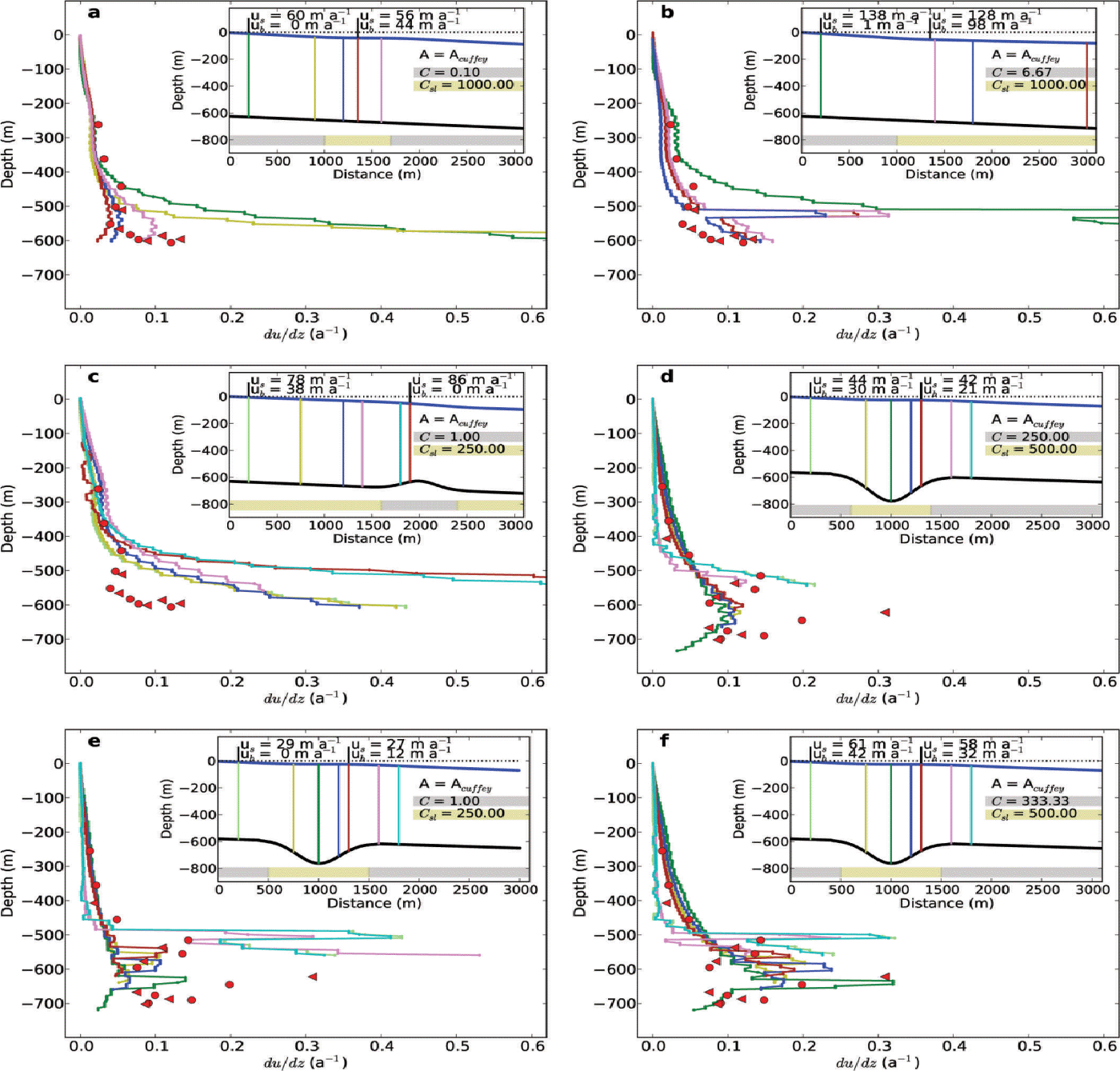
Another set of model runs was performed to reveal the influence of a depression or a bump in bed topography on the ice deformation profile. More complicated bedrock shapes were created with a superposition of Gaussian peaks. With model experiments, such as that shown in Figure 5c, the influence of slippery and sticky bedrock bumps was investigated. The example shown has a sticky bump but, even if the bump is slippery, ice deformation is strongly increased in the vicinity of the bed. The opposite is true for bedrock depressions. Flow model experiments with large bedrock depressions show a reduction of ice deformation within the depression. However, an increase in ice deformation rates occurs at bed depths outside the depression. Such an increase explains the ‘belly’ between 500 and 600 m depth in the ice deformation profile of GULL (Fig. 3e). Examples of model runs with bedrock depressions are shown in Figure 5d–f. In the runs shown in Figure 5e and f a soft layer was introduced to simulate the effect of Wisconsin ice. The flow law parameter A in this layer was enhanced by factors of 2.5–4 (Reference PatersonPaterson, 1991; Reference Thorsteinsson, Waddington, Taylor, Alley and BlankenshipThorsteinsson and others, 1999).
Best-matching model results with simple bedrock shapes (straight, inclined bedrock for FOXX, Gaussian depression for GULL) are shown in Figure 6. We could not reproduce measured surface velocity and deformation profiles precisely with any simple bedrock topography or zone-wise variation of basal slipperiness. However, the most important aspects of the deformation profile at FOXX (nearly constant deformation rates with depth) are reproduced with a model on a flat base with sticky and slippery areas. Figure 6a illustrates that in the center of such a slippery area the shear stress transfer to the bed, and therefore ice deformation close to the bed, is small. For an overall balance of driving force, the basal shear stress and, consequently, ice deformation rates are enhanced on the sticky patch.
Depth profiles of measured and modeled ice deformation at (a) FOXX and (b) GULL. Red symbols indicate vertical gradients of horizontal velocity (dots and triangles for independent boreholes); solid curves are corresponding profiles from model results at several locations of the model domain. The inset shows the locations of these profiles with colored lines, while black and blue curves indicate bed and surface. Green horizontal bars show slippery areas of the bed.
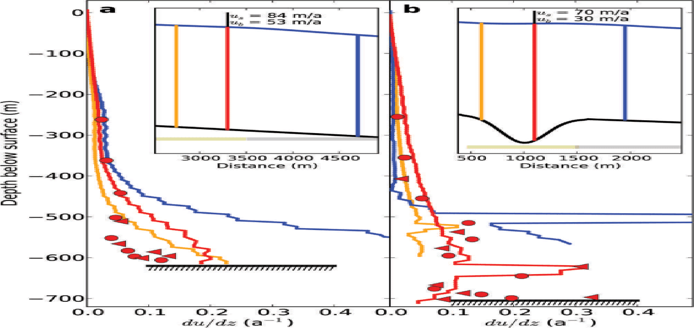
The deformation profile at GULL is qualitatively reproduced if the geometry exhibits a marked depression with a slippery bed. Such a geometry produces shearing strain rates that are higher at half the ice thickness than close to the base (Fig. 6b). High ice deformation rates between 600 and 650 m depth can be reproduced by enhancing the flow law parameter A by a factor of 4. This soft layer likely corresponds to ice from the late Wisconsin, observed in boreholes from the central parts of the ice sheets (Reference PatersonPaterson, 1991; Reference Thorsteinsson, Waddington, Taylor, Alley and BlankenshipThorsteinsson and others, 1999), with enhanced deformation rates of 2.5–4.
Surface velocity paradox
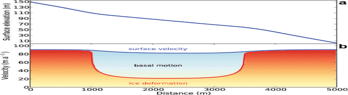
A noteworthy feature of longitudinal stress transfer due to slippery and sticky bed patches is illustrated in Figure 7. The figure shows the surface geometry and velocity from a model experiment (Fig. 6a) with a slippery and a sticky patch, which leads to a flatter surface within the slippery patch (Fig. 7a). The partitioning of surface velocity between ice deformation and basal motion is indicated by colored areas in Figure 7b. Immediately apparent is the paradoxical fact that surface speeds are lower over the slippery bedrock patch than over the sticky patch. This paradox is due to mass continuity and the shape of the ice deformation profiles (e.g. Fig. 6a). In slippery areas with little stress transfer to the base, ice deformation is small and mass flux is mainly due to plug-like flow. On sticky parts of the bed, mass flux has to be provided by ice deformation alone. Since velocity at the base is low, surface velocity is higher than in the slippery patches. An additional effect is the redistribution of driving stress from slippery to sticky areas, increasing the amount of stress transferred to the base there, and consequently increasing ice deformation. This means that high observed surface velocities indicate sticky conditions, whereas lower surface velocities indicate slippery conditions. Any local or vertically integrated theory will overestimate ice deformation on slippery patches, and underestimate ice deformation on sticky parts.
(a) Surface elevation. (b) Modeled velocities over an inclined flat bed with slippery and sticky basal conditions (model experiment shown in Fig. 6a). The blue curve shows surface velocity, the red curve shows surface velocity due to ice deformation and the blue area corresponds to basal motion.
Conclusions
Borehole deformation measurements at three sites in the western ablation area of the GrIS show a 44–73% contribution of basal motion to surface velocity in winter, and episodically up to 90% during speed-up events in summer. Such high ratios of basal motion are probably a local phenomenon, as elucidated by the model experiments. A patchy bed with slippery and sticky areas and topographic depressions leads to surface velocities and vertical ice deformation profiles that are similar to those measured at two sites on the ice sheet. These profiles exhibit an unusual shape, which is likely an expression of horizontal stress transfer from slippery to sticky patches, and from subglacial depressions to hills.
Overall, the agreement of modeled and measured deformation rates in the upper part of the ice column shows that the flow law parameter n = 3 and the temperature-dependent rate factor A of Reference Cuffey and PatersonCuffey and Paterson (2010) are a good choice for ice-sheet models. The remaining discrepancies in the lower part might be due to complex local bed geometry or effects of 3-D flow not considered with the flowline model, or might indicate that the commonly assumed ice rheology (isotropic viscous) is inadequate. Nevertheless, the modeling exercise shows that the best-matching model runs implement a geometry that is similar to that measured with ice radar.
The fact that both our drill sites are located at the downstream end of a slippery bed patch or within a basal depression is due to the corresponding surface topography with flat areas (Fig. 7a), where compressive flow and local surface depressions favor a relatively uncrevassed surface with streams and lakes. Such conditions are ideal drill sites, compared with heavily crevassed areas located over sticky or hilly bedrock. It is therefore likely that our borehole data are biased to one specific setting without exploring the full range of possible stress states and, thus, ice deformation patterns (Reference LüthiLüthi, 2013).
Flow model experiments show some noteworthy properties of longitudinal stress transfer that impact the interpretation of measured velocities and results from ice-sheet models. Horizontal stress transfer, the corresponding surface geometry and resulting vertical ice deformation profiles (plug flow vs shear flow) lead to the counter-intuitive configuration that areas with a slippery bed are thinner, flatter and have lower surface velocity than sticky areas (Fig. 7). Analyzing such surface velocity variations with simple ice deformation profiles (e.g. the often assumed shallow-ice approximation; Reference HutterHutter, 1983) leads to incorrect partitioning of surface velocity between basal and internal deformation, as illustrated in Figure 3 by our measured depth profiles of ice deformation, which differ considerably from the simple assumptions.
Our borehole deformation measurements and model calculations highlight that horizontal stress transfer from slippery to sticky areas, and from subglacial depressions to hills, plays an important role in controlling ice flow in the temperate-based marginal areas of the GrIS. Similar conclusions have been drawn about stress transfer to the margins in fast-flowing ice streams through deeply eroded bedrock channels (Reference Lüthi, Funk and IkenLüthi and others, 2003; Reference Truffer and EchelmeyerTruffer and Echelmeyer, 2003). These observations underline the importance of using higher-order numerical flow models to adequately represent ice flux, not only in the fast-flowing outlet glacier catchments, but in all areas of the ice sheet where the bed is at melting temperature and basal motion is not negligible.
Author Contribution Statement
C.R. and M.P.L. analyzed borehole sensor data, performed model experiments and wrote the paper; L.C.A. and M.J.H. analyzed the GPS data; S.S.K. analyzed the DTU airborne radar survey from 2005. All authors performed the fieldwork, discussed the data and commented on the paper.
Acknowledgements
We thank several people who were essential in this project: Cornelius Senn, Edi Imhof, Thomas Wyder, Martin Funk, Andreas Bauder, Christian Birchler, Michael Meier, Blaine Moriss and Fabian Walter. This project was supported by Swiss National Science Foundation grant 200021_127197, US National Science Foundation grants OPP 0908156, OPP 0909454 and ANT-0424589 (to CReSIS), NASA Cryospheric Sciences, and Climate Modeling Programs within the US Department of Energy Office of Science. Logistical support was provided by CH2M HILL Polar Services. GPS receivers were provided by UNAVCO. We also acknowledge the help of pilots and airport cargo staff of Air Greenland in Ilulissat. We thank ‘Microwave and Remote Sensing, DTU Space, the Technical University of Denmark’ for providing bedrock topography data of the area. We acknowledge the use of Rapid Response imagery from the Land Atmosphere Near-real time Capability for EOS (LANCE) system operated by the NASA Goddard Space Flight Center’s Earth Science Data and Information System (ESDIS) with funding provided by NASA HQ.
Appendix A: Diboss – Digital Borehole Sensor System
The digital borehole sensor system DIBOSS (custom-developed at ETH Zürich) is an improved version of an earlier system (Reference Lüthi, Funk, Iken, Gogineni and TrufferLüthi and others, 2002). The sensor system works in a master–slave mode with communication over four-wire cables on a RS-485 serial bus. Each multi-sensor unit consists of a programmable microprocessor, and digital sensors for pressure (Keller 7LX), temperature (IST TSic-716,±70 mK absolute), two-axis tilt (VTI SCA103T differential, 0.001˚ resolution) and magnetic field (PNI Micromag 3). All tilt sensors were individually calibrated at 52 prescribed angles.
The multi-sensor units are protected against pressure in machined aluminum tubes of 210 mm length and 50 mm diameter. Tube lids are sealed with double O-rings and contain a mounting hole for the pressure sensor. Cables are soldered on specially machined cable feed-throughs in the lids, sealed with potting compound and mechanically protected from bending forces.
The DIBOSS master unit is controlled by a CR-1000 Campell data logger used for switching power supply, addressing individual multi-sensor units and storing instrument readings on external compact flash memory (CFM100 storage module). For communication and power supply a special extensible cable (Cortland Cable Co) with six cores and a central Kevlar member was used. The system is protected against short circuits from cable rupture by testing the resistance of each cable segment between two sensing units before a connection is established.
The sampling interval was set to 10 min in summer, and was automatically reduced depending on battery voltage. All four deployed DIBOSS systems ran continuously for more than a year on a power supply with three 65 Ah batteries, recharged by a steel solar panel (20 W) mounted on top of the logger box.
Appendix B: Tilt Data
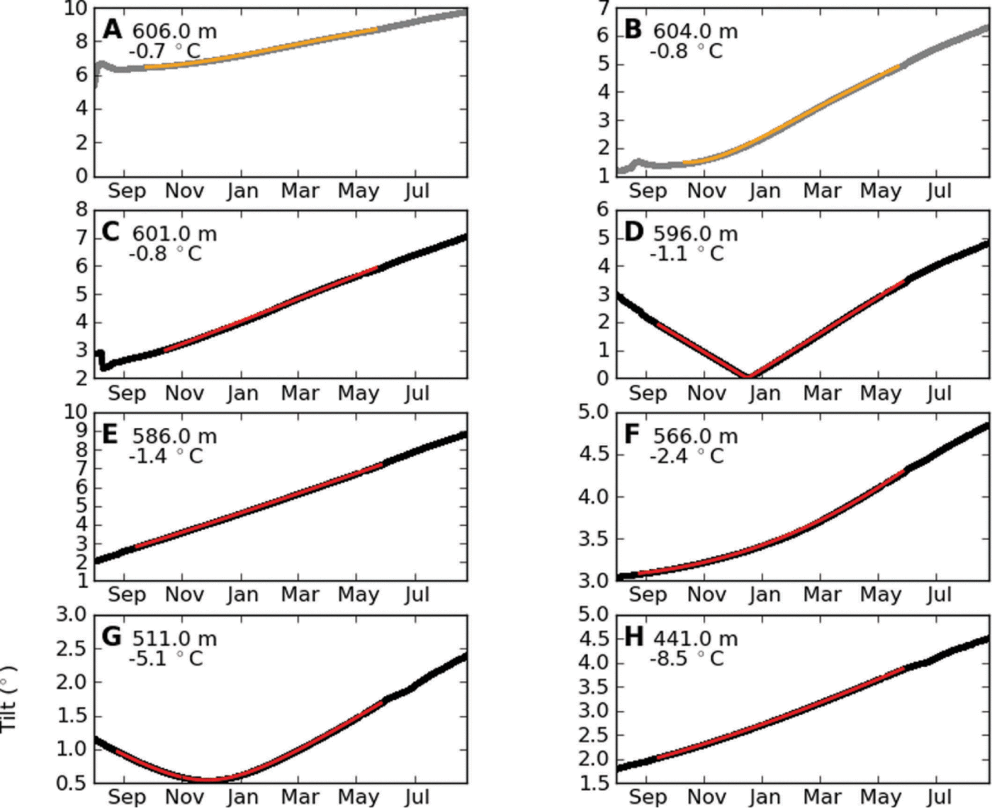
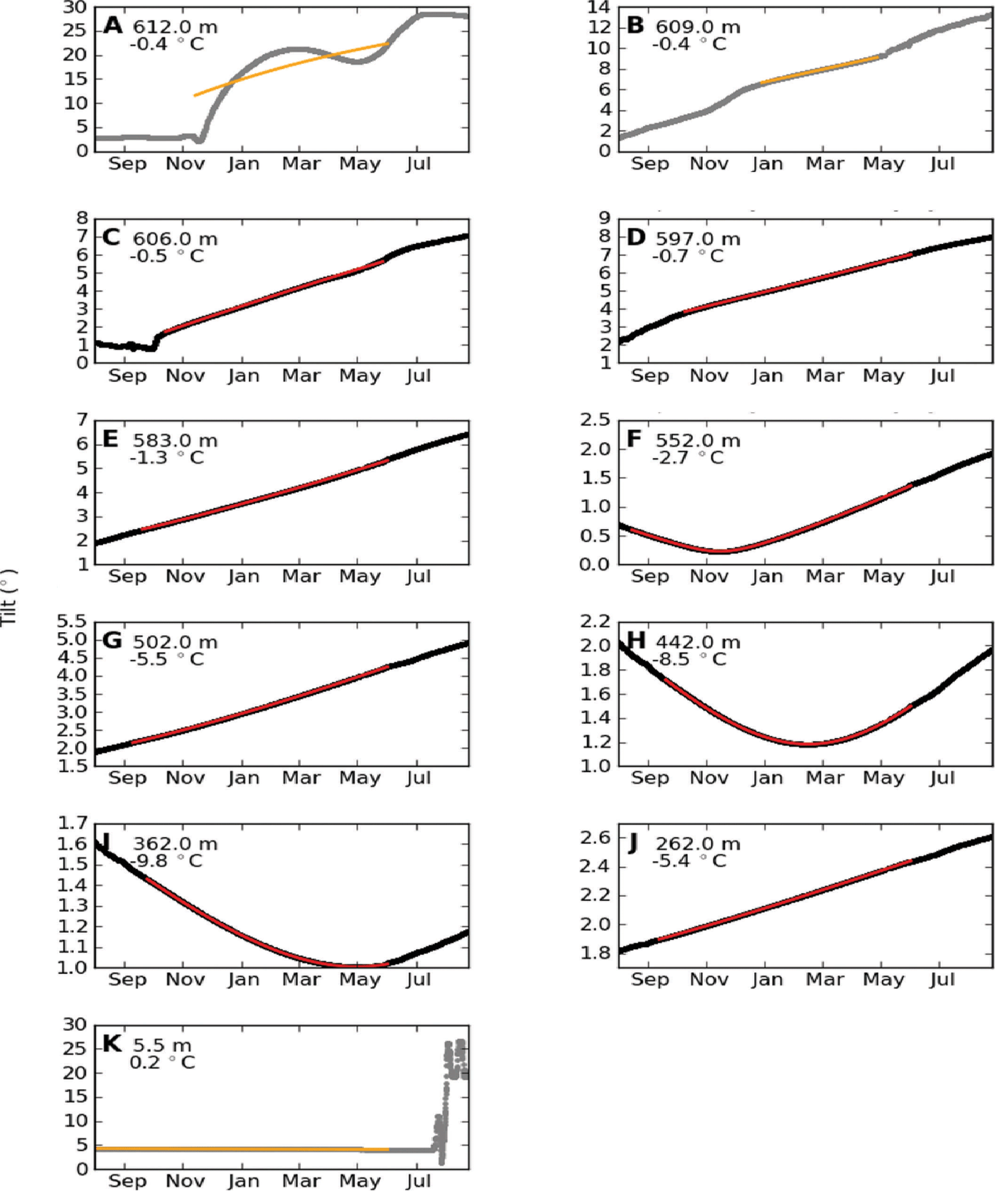
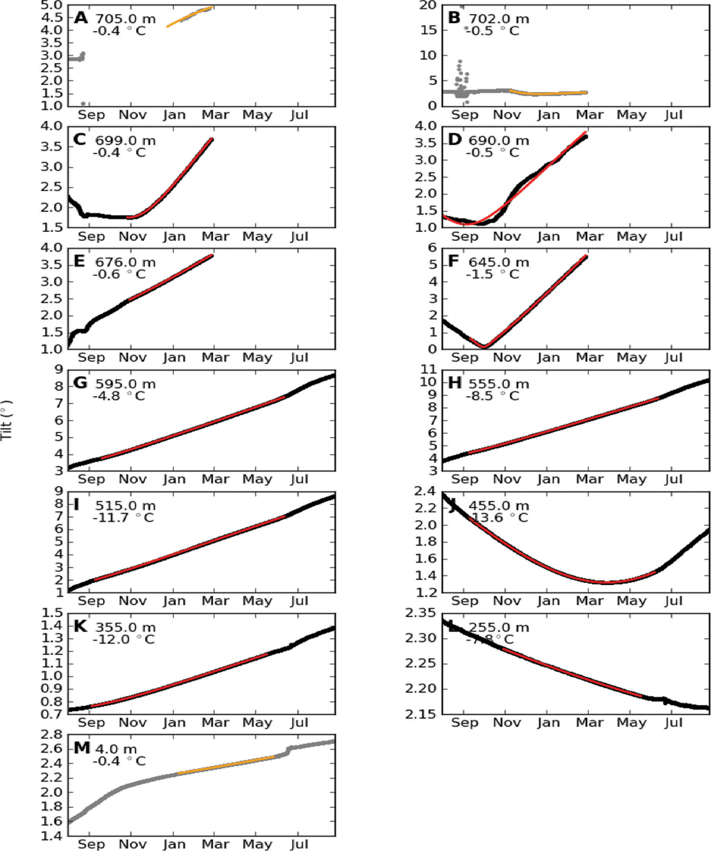
Tilt data for FOXX and GULL with string1 and string2 are shown in Figures 8–11.
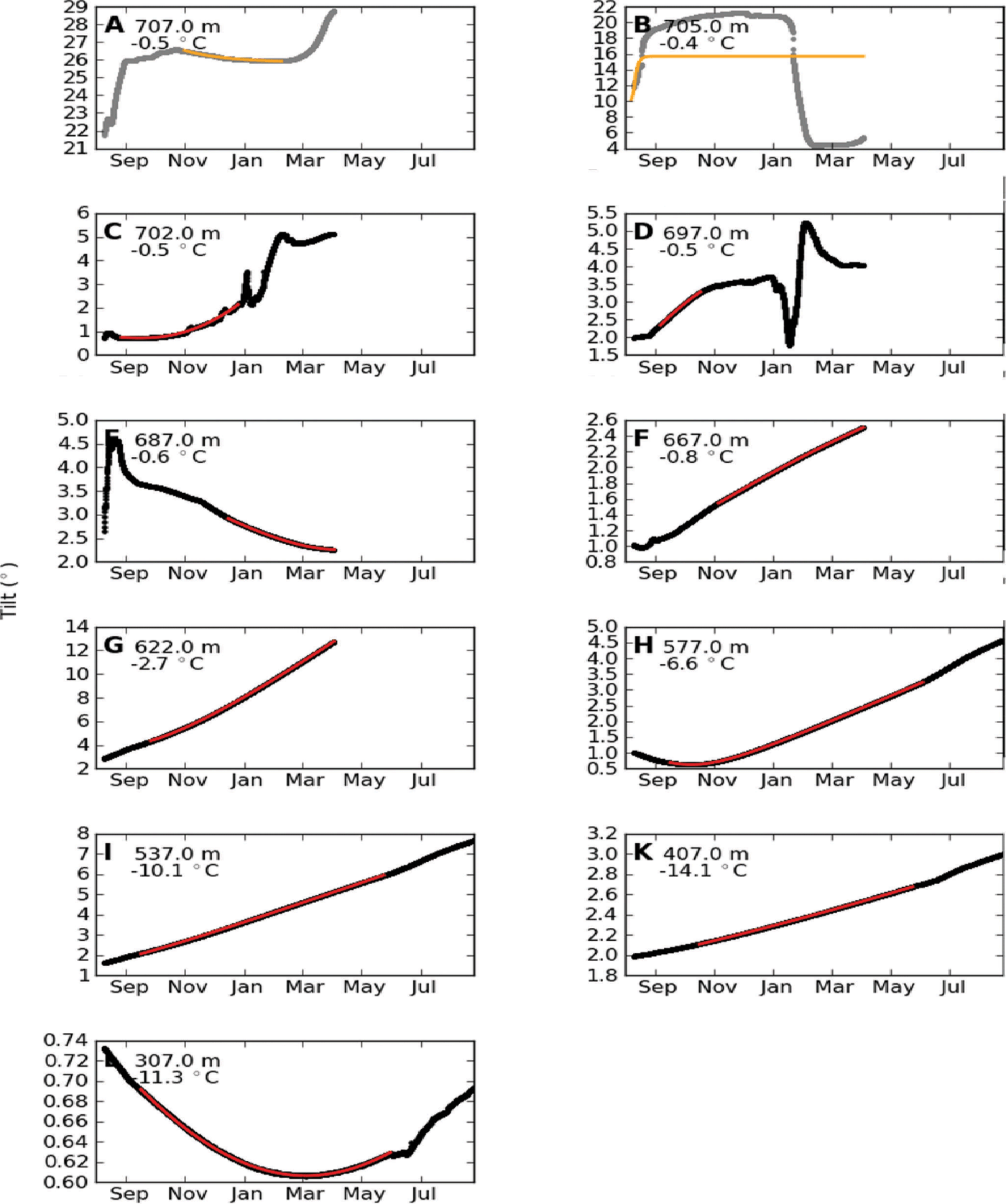
Tilt evolution of sensors A (lowermost) to H (uppermost) from DIBOSS string1 at FOXX. Data are shown in black; depths below surface and ice temperature are indicated in the upper left corner of each panel. The result of the fitting procedure with method A (Reference Keller and BlatterKeller and Blatter, 2012) is shown with colored lines. Data from sensors with bad fits are displayed in gray and orange and were not used in the evaluation.
Tilt evolution of sensors from DIBOSS string2 at FOXX. See Figure 8 for description.
Tilt evolution of sensors from DIBOSS string1 at GULL. See Figure 8 for description.
Tilt evolution of sensors from DIBOSS string2 at GULL. See Figure 8 for description.
Appendix C: Determined Velocity Gradients
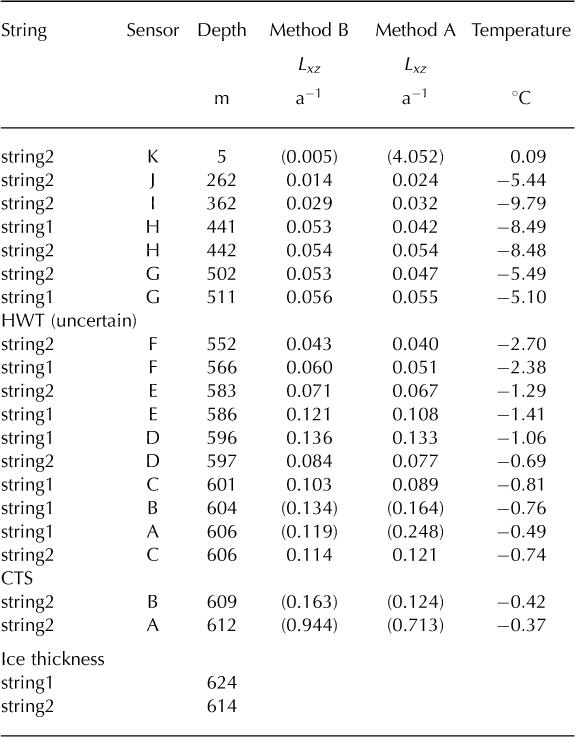
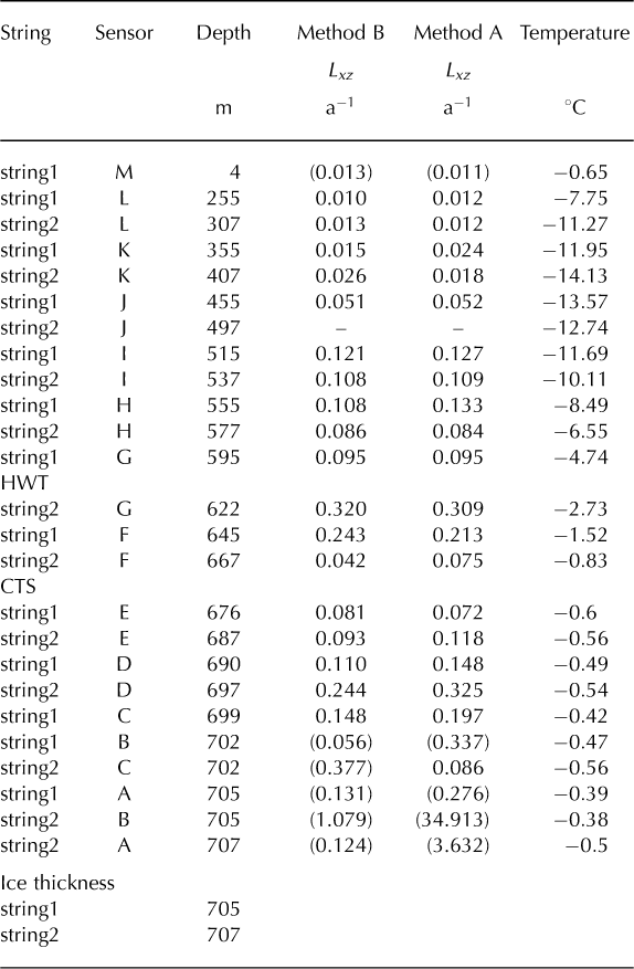
Deformation rates and ice temperature for all sensors at FOXX and GULL are given in Tables 2 and 3.
Deformation rates and ice temperature for all sensors at FOXX. Values in parentheses are not used for calculations (data could not be fitted)
Deformation rates and ice temperatures at GULL. Values in parentheses are not used (data could not be fitted). The HWT is likely between 600 and 610 m; all sensors below were lost in spring 2012, presumably due to cable rupture.


 Open access