

1. Introduction
Variations in surface ice motion within hours to a day have been observed on numerous glaciers (e.g. Reference IkenIken 1977; Reference Sugiyama and GudmundssonSugiyama and Gudmundsson, 2004). To analyze such behavior, it is important to obtain accurate information on the surface ice motion. Traditional standard geodetic methods such as differential GPS or optical laser measurements (i.e. an automated tachymeter) are state of the art in field glaciology and have been applied in numerous studies. With these methods, detailed temporal information on the ice displacement at local observation points on the glacier can be obtained. To analyze the ice-flow regime of a glacier, one usually requires a network of observation points equipped with optical mirrors or GPS receivers. The set-up and maintenance of such a flow survey network can become costly if the target glacier is large and possibly difficult to access. For 20 years, spaceborne interferometric synthetic aperture radar (InSAR) imaging has been successfully used to observe surface elevation (i.e. generation of digital elevation models) and the flow of ice streams and ice sheets in remote areas such as Antarctica and Greenland (Reference Fahnestock, Bindschadler, Kwok and JezekFahnestock and others, 1993, Reference Joughin, Winebrenner and FahnestockJoughin and others, 1995, Reference Joughin, Kwok and Fahnestock1996, Reference Joughin, Kwok and Fahnestock1998; Reference Mohr, Reeh and MadsenMohr and others, 1998; Reference Bamber, Hardy and JoughinBamber and others, 2000). In these studies, differential repeat-pass interferometry techniques (D-InSAR) were mainly used (Reference Bamler and HartlBamler and Hartl, 1998). Nowadays, spaceborne synthetic aperture radar (SAR) imagery can resolve cells as low as a few metres in azimuth and ground range directions. The investigation period is restricted to the time the satellite passes and revisits the target on appropriate orbits, which limits temporal resolution to one or a few particular days (ESA, 2007).
Here we apply a novel ground-based and portable real aperture radar device (Reference Werner, Strozzi, Wiesmann and WegmüllerWerner and others, 2008) for interferometric imaging of the surface ice motion of an Alpine glacier. The Gamma Portable Radar Interferometer (GPRI) is able to acquire phase signal images of the observation area at a repeat interval as low as 20 min. We employed the GPRI on Gornergletscher, Switzerland, (Fig. 1a) in order to monitor sub-daily to daily variations of the surface ice motion of Gornergletscher. These variations in surface ice motion were triggered by the subglacial drainage of the adjacent marginal, ice-dammed lake Gornersee. We present ice displacement maps derived from the GPRI interferograms and analyze the performance of the radar device for remote sensing of surface ice motions of a glacier on spatial and temporal scales lower than in conventional D-InSAR applications. We compare the radar displacements against local in situ ice displacement measurements. To complete the study, a brief discussion of the observed displacements in relation to the drainage phenomena is given.
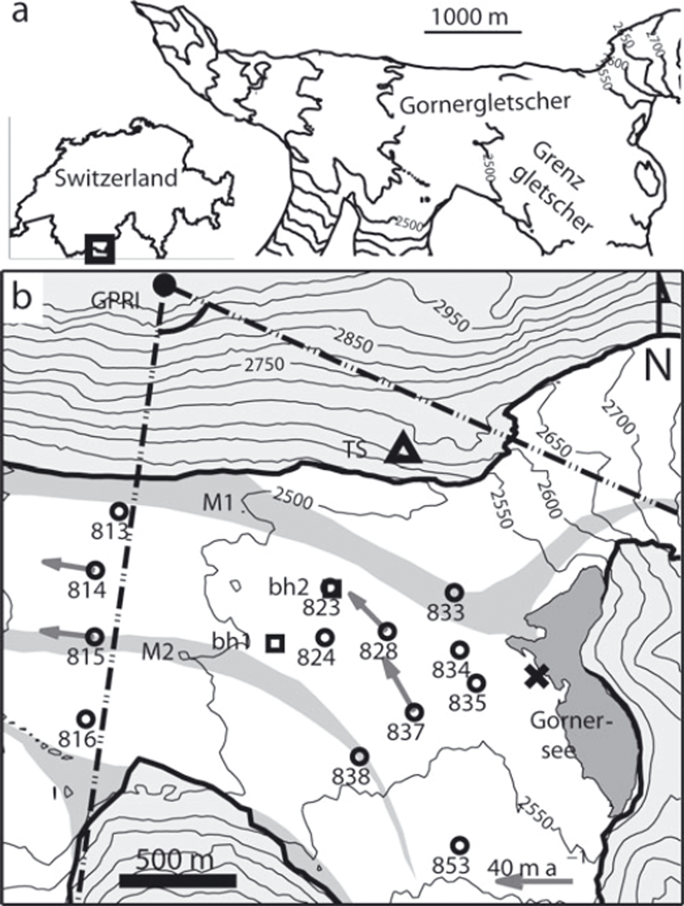
(a) Geographic position of the field site with overview of the tongue of Gornergletscher with 50 m surface elevation contours and Gornersee (dark grey). (b) Detailed map of the study area on Gornergletscher with 50 m surface elevation contours, debris-covered moraines M1 and M2 (grey), local ice displacement measurement points (circles), site of GPS reference and tachymeter (triangle TS), boreholes bh1 and bh2 for water level measurements (squares), GPRI location (dot), scan sector (dot-dashed), and location of an excavated subglacial drainage channel (cross). The arrows at markers 814, 815, 828 and 837 indicate annual ice-flow velocities.
2. Field Methods
Gornergletscher is located in southern Switzerland and is the name-giving tributary to the ablation tongue formed by the confluence of Gornergletscher and Grenzgletscher (Fig. 1). Gornergletscher features two distinct moraines (M1 and M2 in Fig. 1b) of which the medial moraine M1 is severely displaced to the northern margin of Gornergletscher due to the thinning and decreased mass delivery from Gornergletscher tributary. The ice-marginal lake Gornersee is located at the junction of the two tributaries, ∼5 km upstream of the terminus, (Fig. 1b). The yearly subglacial drainage of Gornersee by the adjacent Gornergletscher was investigated extensively during the years 2004–08 (Reference Huss, Bauder, Werder, Funk and HockHuss and others 2007; Reference Sugiyama, Bauder, Weiss and FunkSugiyama and others, 2007, Reference Sugiyama, Bauder, Huss, Riesen and Funk2008; Reference Walter, Deichmann and FunkWalter 2008; Reference Werder and FunkWerder and Funk 2009; Reference Werder, Loye and FunkWerder and others, 2009; Reference Riesen, Sugiyama and FunkRiesen and others, 2010).
2.1. Surface ice motion measurements
We installed the GPRI during the drainage of Gornersee in June 2008 and surveyed the surface ice motion of Gornergletscher across ∼3 km2 of the glacier surface downstream of Gornersee. As the radar was in operation, we carried out in situ ice displacement measurements at 13 marker positions located approximately within the target survey area.
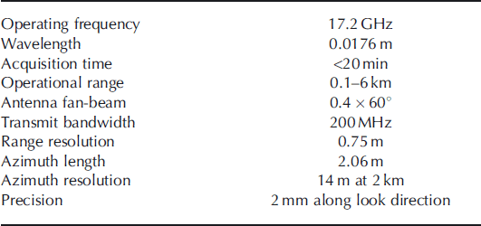
The GPRI was constructed by Gamma Remote Sensing (GRS). It operates at 17.2 GHz, which is higher than the spaceborne SAR operating frequency of 1–10 GHz. Detailed characteristics of the GPRI are summarized in Table 1. The GPRI is designed as a portable system; the device is mounted on a tripod and is promptly installed in remote areas, provided power supply can be ensured. The GPRI acquires a microwave image of the target area of 90° azimuth range in ∼20 min. The device carries a secondary receiver antenna at slightly different look direction than the primary antenna. The simultaneous acquisition of pairs of microwave images permits generation of a DEM of the surveyed topography alongside the displacement measurements.
Key characteristics of the Gamma Portable Radar Interferometer (GPRI)
The analysis of the GPRI microwave images follows differential interferometry processing techniques (Reference Bamler and HartlBamler and Hartl, 1998; ESA, 2007), which includes phase unwrapping, filtering, conversion of the phase-difference signal to scalar displacements, and geolocalization. All these tasks were carried out by GRS. Multiple subsequent images can be integrated into an interferogram as long as the images remain sufficiently coherent. In this way, GRS produced displacement maps based on 5 hour interferograms.
In spaceborne InSAR imaging the device is located high above the target. Thus, the vector of the line-of-sight direction (LOSD) is dominated by the elevation difference between satellite and ground, and is assumed to be the same for all resolution cells (interferogram pixels) of the interferogram, since the lateral extent (azimuthal and ground range) is much smaller. For ground-based interferometry using the GPRI, this does not apply, since the elevation difference between device and target area may be similar to or smaller than the operational range. Thus, for the ground-based GPRI survey, each resolution cell is assigned an individual LOSD vector on which the phase signal is determined.
We intended to monitor the spatial variations of the ice motion at the ice dam (the confluence area in the vicinity of Gornersee). The radar was targeted at the principal area at a distance of 0–1200 m from Gornersee, laterally confined by the two moraines, M1 and M2 (Fig. 1b). In the same area the in situ ice displacement measurements were carried out. Figure 1b shows the locations of 13 markers set up for the local ice-motion measurements; for orientation purposes the mean annual ice-flow directions are indicated in the primary target area at stakes 837 and 828.
The markers used for the in situ ice-displacement measurements were ice-anchored aluminum poles equipped with optical mirrors. From the mirror reflectance pattern of each marker, the tachymeter automatically determined azimuth and relative distance at a sampling interval of 1 hour. The readings were corrected for atmospheric refraction by using fixed reference markers installed at known positions along the glacier margin, thus covering different distances and azimuth directions. From the angular records and the known position of the tachymeter, the positions of the markers and the resulting displacement trajectories were calculated. The accuracy of the position estimates is about ±5 cm. A detailed account of the survey technique and associated error estimates is given by Reference Gudmundsson, Bassi, Vonmoos, Bauder, Fischer and FunkGudmundsson and others (2000) and Reference Riesen, Sugiyama and FunkRiesen and others (2010).
In order to compare the in situ measured displacements to the displacements observed by the radar, we chose nine reference markers (823, 824, 828, 833–835, 837, 838, 853) at which we additionally installed corner reflectors. This enabled identification of the marker locations in the radar interferograms, as the steel panel reflectors are highly reflective.
Three markers, 824, 834 and 837 (Fig. 1b), were equipped with GPS receivers (Leica GPS500) instead of optical mirrors. Simultaneously, a fixed GPS reference site, located close to the tachymeter, was operated. We performed a differential GPS analysis and processed the data in kinematic mode with a sampling interval of 2 min using Track software (Reference ChenChen, 1998; Reference KingKing, 2004). The accuracies of the positions estimated by kinematic GPS are on the same order as those estimated optically by the tachymeter (Reference Riesen, Sugiyama and FunkRiesen and others, 2010). The exact positions of the tachymeter, the GPS reference station and the GPRI were determined with GPS precise point positioning (PPP; CGS, 2008). In this way, a consistent frame of reference for all position estimates was provided, minimizing translation errors.
In addition, an ultrasonic ranger device was operated at the location of marker 837, continuously measuring surface ablation during the lake drainage/radar survey time. Each day, we also recorded the local ice melt at each of the marker locations. The ice surface motion measurements were supplemented by measurements of subglacial water pressure in boreholes, which were drilled to the glacier bed and equipped with pressure sensors.
3. Results
3.1. Drainage of Gornersee
Gornersee filled continuously until 20 June when, at 0700 h CEST (Central European Summer Time), a decrease of lake water level was noticed. The lake water level started to decrease around 0000 h on 20 June (Fig. 2). Gornersee drained more and more rapidly and emptied in <4 days. After the lake was fully drained we inspected the lake basin and detected a large channel (>15 m diameter) at the southwestern lake shore plunging into the ice of Grenzgletscher in the southwest direction (Fig. 1, cross). The level of the channel roof was ∼ 5–10 m lower than the surface elevation of the surrounding ice dam.
Evolution of lake water level (thick solid curve) of Gornersee and water level (w.l.) in boreholes bh1 (dashed curve) and bh2 (thin solid curve). The interval between the two vertical lines (solid grey) marks the duration of the lake drainage.
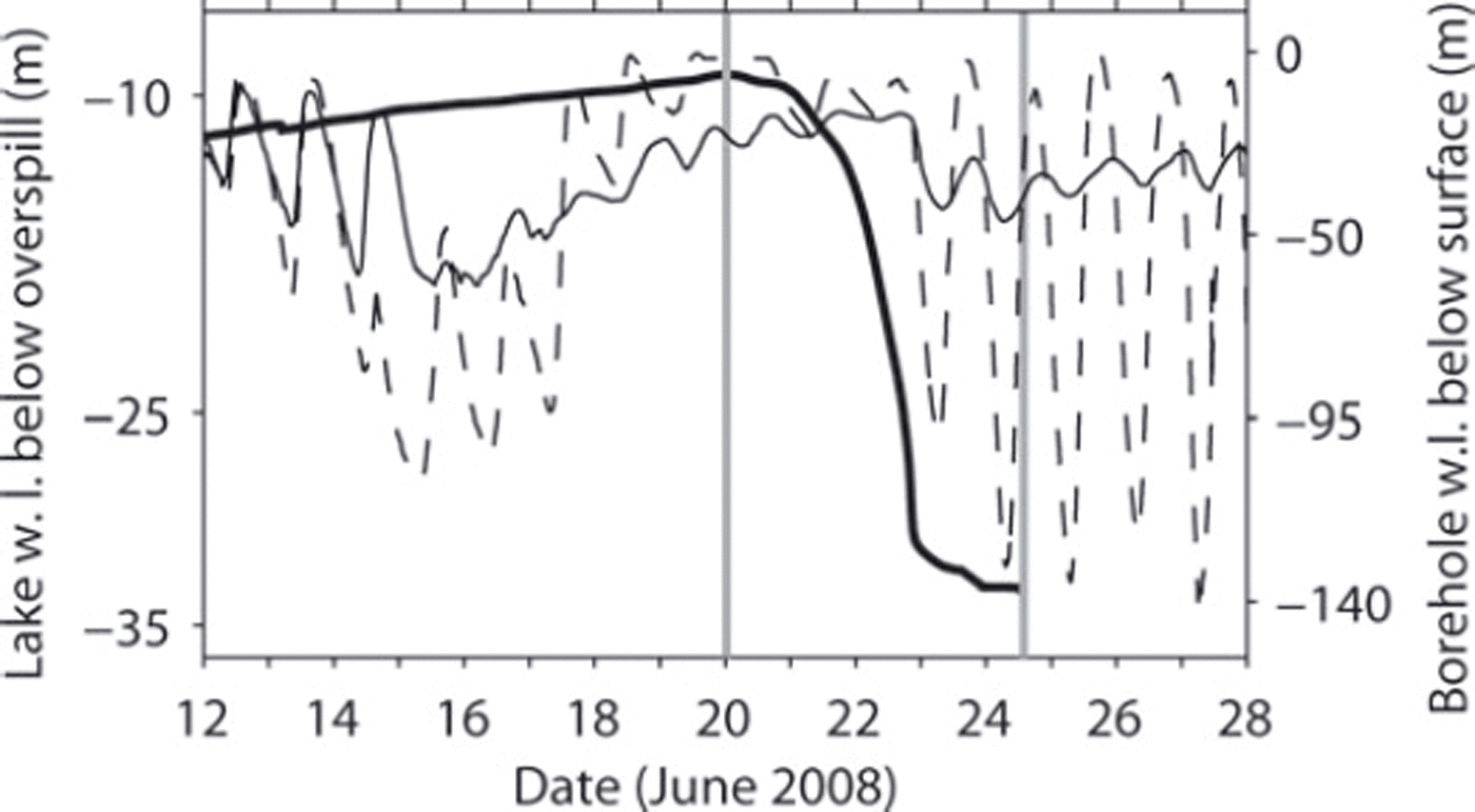
Before 14 June, the water level in the boreholes, bh1 and bh2, synchronously fluctuated diurnally with comparable amplitude (Fig. 2). On 15 June, the water level in bh1 dropped almost 100 m, continued to oscillate diurnally, then rose again sharply on 17 June, remaining at a high level until 23 June. In bh2, the diurnal oscillations were interrupted on 15 June and the water level increased slowly until 23 June without significant fluctuations. From 23 June onwards, the water level started to fluctuate again diurnally, with large amplitude variation in borehole bh1, and small amplitude variation in bh2.
These observations suggest the subglacial drainage system was undergoing some change already before the decrease of lake water level was observed on 20 June. Presumably, the disruption of the diurnal borehole water level fluctuations on 15 June and the successive increase of the water levels were caused by lake water subglacially leaking from Gornersee prior to the superficial decrease of lake water level on 20 June. We suppose the leakage developed into a subglacial channel, which accomplished the complete drainage of Gornersee within 4 days (20–24 June). Most likely, the aforementioned excavated channel was the opening of this major drainage channel.
3.2. Surface ice displacements
The GPRI was in operation between 2000 h on 21 June and 1200 h on 25 June. Due to failure caused by current peaks in the power supply, the device did not operate between 0900 h on 23 June and 1800 h on 24 June. From 55 hours of operation time we obtained 44 hours of useful data, which corresponds to 133 20 min interferograms. As main product, GRS produced several 5 hour interferograms from these data.
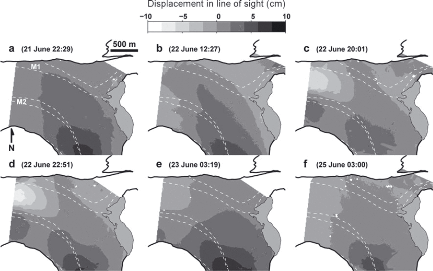
In Figure 3, the displacement maps derived from six 5 hour interferograms are presented. The corresponding acquisition time information is given in Table 2. In the map of Figure 3a, the displacement pattern resembles a typical map of glacier flow velocities, i.e. the largest displacements are located upmost on Grenzgletscher. The displacement magnitude decreases along M2 (in the along-flow direction) and towards the margins (in the cross-flow direction). Generally, the ice moves towards the GPRI (positive displacements), but, down-glacier of the confluence area where the LOSD becomes aligned normal to the principal direction of the ice motion (now to the west), the GPRI did not detect any motion. On the evening of 20 June, the situation changed significantly (Fig. 3c). Below the confluence, strong negative displacements were recorded between M1 and M2. Along the LOSD in the cross-flow direction, a transition of negative to positive displacements occurs across the moraine M2. This displacement anomaly is also present in Figure 3d and then starts to diminish in Figure 3e. In the confluence/ice-dam area, i.e. the primary target area, the observed displacements were small and varied marginally. We expected to record larger displacements in the ice-dam area according to other drainage events from the previous years, 2004 and 2007 (e.g. Reference Sugiyama, Bauder, Weiss and FunkSugiyama and others, 2007), in which the surface ice-motion regime was perturbed more conspicuously. In summary, we observed two clear signals: minor displacements and changes in the confluence and lake vicinity area, and striking displacement variations down-glacier below the confluence area.
Acquisition time periods (CEST) for the 5 hour interferograms underlying the displacement maps of Figure 3a–f
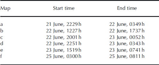
(a–f) Displacement maps derived from six 5 hour interferograms. Negative displacement is away from the radar on the line-of-sight direction (LOSD) while positive displacement is towards the radar on the LOSD. Dashed white curves indicate the side margins of moraines M1 and M2. Date and start times are indicated.
3.2.1. Comparison to in situ measured displacements
In the following, we refer to the displacements measured by the radar as observed displacements, whereas those obtained from in situ markers are referred to as measured displacements. The corner reflectors attached to the nine reference markers already mentioned were easily identified in the interferograms due to the high reflectivity of the steel panels. The flow velocities of Gornergletscher in the target area are <1 m d−1, so none of the markers was displaced >0.7 m in any direction while any interferogram was integrated. Thus, for localization of the corner reflector positions in the radar interferogram, the locations of the markers were treated as constant. Therefore, each marker location corresponded to the interferogram pixel in which the reflection from the corner reflector was identified. During a 5 hour interferogram interval, five positions of a marker were usually measured by the tachymeter, whereas at a marker equipped with a GPS receiver, 150 data points were acquired during the same time span. From the array of j = 1…N measured positions at a marker, denoted as vector ![]() , we determined the actual measured three-dimensional displacement vector during the interferogram (IF) time, Δt
IF, as
, we determined the actual measured three-dimensional displacement vector during the interferogram (IF) time, Δt
IF, as
where v is the velocity vector, of which the components, vi
, were estimated as least-square fits of linear polynomials, ![]() , to the data points, x, in each of the spatial components, i ∈ [1, 2, 3].
, to the data points, x, in each of the spatial components, i ∈ [1, 2, 3].
For each marker, we computed the LOSD unit vector, e*, as the normalized difference between the position of the GPRI and the average of the measured positions. Projecting dm onto e* yields the scalar component of dm in the direction of the line of sight as
which can be directly compared to the observed displacements of the GPRI. However, it was not guaranteed that at every marker all points (N = 5; or N = 150 for GPS markers) were available, as sometimes data points were missing due to malfunction or low visibility. Because the in situ measurements were sometimes sparse at several marker locations, we decided to compute the displacement vector at a marker from the acquired positions within the interferogram time enlarged by an additional ±3 hours of buffering time. In this way, a few more data points, acquired before and after the 5 hour interferogram interval, were incorporated, increasing N slightly. Due to the uncertainties of the individual marker position estimates, the estimate of a displacement vector from these very sparse data points might not be representative. Using an enlarged time interval with more data points and fitting the velocity vector using Equation (1) to the data improves the estimate, provided the time interval is not enlarged too much. This is why we fitted a velocity vector to the data and then scaled the velocity by the interferogram time, Δt
IF, to estimate dm in Equation (1). We tried different lengths of additional buffer time and found that the agreement between ![]() and the observed displacement from the GPRI (denoted henceforth by d*) is best when using ±3 hours of buffer time (section 3.2.3).
and the observed displacement from the GPRI (denoted henceforth by d*) is best when using ±3 hours of buffer time (section 3.2.3).
3.2.2. Ablation correction
Changes of the ice surface motion of Gornergletscher in June are a combination of ice displacement and surface melt. From the diurnal melt signal of the ultrasonic ranger and the local melt measurements at each marker we constructed simple melt functions to estimate the melt component during an interferogram. The (negative) melt component could then be added to dm of each marker if desired.
3.2.3. Verification and error analysis
In the following, we compare the scalar projections, ![]() , of the marker displacements against the displacements extracted from the GPRI maps (distribution of d*) by quantifying the discrepancies,
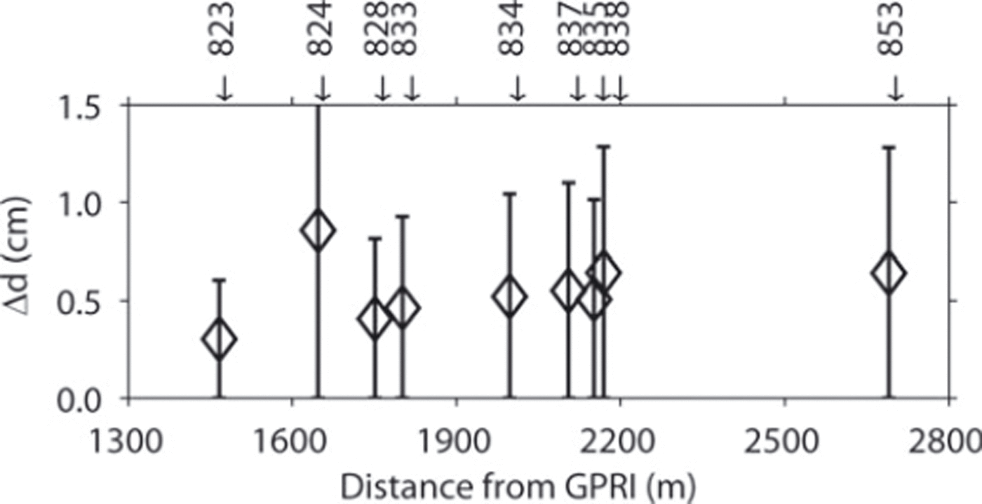
, of the marker displacements against the displacements extracted from the GPRI maps (distribution of d*) by quantifying the discrepancies, ![]() , in detail. In Figure 4, we depict the mean of Δd from the six available displacement maps at each marker, with ±1 standard deviation, σ, the markers being sorted in increasing distance from the GPRI. The error magnitude increases slightly with increasing distance from the GPRI, but this trend is not significant. We compared the measured
, in detail. In Figure 4, we depict the mean of Δd from the six available displacement maps at each marker, with ±1 standard deviation, σ, the markers being sorted in increasing distance from the GPRI. The error magnitude increases slightly with increasing distance from the GPRI, but this trend is not significant. We compared the measured ![]() with the observed, d
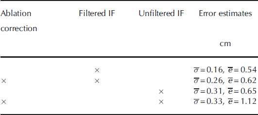
* displacement in several different combinations, i.e. (1) marker displacements corrected for ablation, (2) no ablation correction, (3) the observed displacements extracted from the unfiltered (raw) or (4) from the filtered (smoothed) displacement maps. The error estimates from these combinations are shown in Table 3. We notice that lowest standard deviations and smallest mean errors are achieved when settling with the filtered interferograms and not incorporating an ablation correction. The agreement between observed and measured displacements is acceptable, despite the considerable variance. The mean of the absolute displacements,
with the observed, d
* displacement in several different combinations, i.e. (1) marker displacements corrected for ablation, (2) no ablation correction, (3) the observed displacements extracted from the unfiltered (raw) or (4) from the filtered (smoothed) displacement maps. The error estimates from these combinations are shown in Table 3. We notice that lowest standard deviations and smallest mean errors are achieved when settling with the filtered interferograms and not incorporating an ablation correction. The agreement between observed and measured displacements is acceptable, despite the considerable variance. The mean of the absolute displacements, ![]() , at a marker ranges between 1 and 5 cm and that of the differences, Δd, is 0.5–1 cm, which corresponds to relative errors of 16–30% (Table 4). The mean relative error of the differences at all stakes excluding 833 is 29%. The best agreement between measured and observed displacement was obtained at marker 853 (Table 4), which is located upmost on Grenzgletscher (Fig. 1b), where flow velocities are highest and thus displacements are largest.
, at a marker ranges between 1 and 5 cm and that of the differences, Δd, is 0.5–1 cm, which corresponds to relative errors of 16–30% (Table 4). The mean relative error of the differences at all stakes excluding 833 is 29%. The best agreement between measured and observed displacement was obtained at marker 853 (Table 4), which is located upmost on Grenzgletscher (Fig. 1b), where flow velocities are highest and thus displacements are largest.
Mean values of the absolute differences, Δd, between the ‘observed’ displacement (as measured by the GPRI in line-of-sight direction, LOSD) and ‘measured’ displacement (as obtained at the in situ marker positions and projected onto LOSD) from the six 5 hour interferograms at each of the nine reference markers. Error bars correspond to 1 standard deviation.
Mean standard deviations, ![]() , and mean absolute errors,
, and mean absolute errors, ![]() , of the differences between ‘observed’ displacement (as measured by the GPRI in line-of-sight direction, LOSD) and the ‘measured’ displacement (as measured at the in situ marker positions and projected onto LOSD). The values refer to the results when different data combinations as indicated by the crosses are used (IF = interferogram)
, of the differences between ‘observed’ displacement (as measured by the GPRI in line-of-sight direction, LOSD) and the ‘measured’ displacement (as measured at the in situ marker positions and projected onto LOSD). The values refer to the results when different data combinations as indicated by the crosses are used (IF = interferogram)
Mean values of observed absolute displacements, ![]() , mean absolute errors,
, mean absolute errors, ![]() , and mean relative error,
, and mean relative error, ![]() , from the six interferograms, relative to the ‘measured’ displacement projected onto LOSD, at each marker. The horizontal angle, α, between e* and the mean horizontal marker displacement direction is also indicated
, from the six interferograms, relative to the ‘measured’ displacement projected onto LOSD, at each marker. The horizontal angle, α, between e* and the mean horizontal marker displacement direction is also indicated
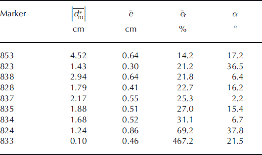
In Table 4 we also indicated the angle of incidence, α, between the horizontal LOSD and the mean displacement vectors for each stake. There is no clear correlation indicating that displacements are better measured when LOSD and flow directions are aligned. The alignment therefore plays a minor role.
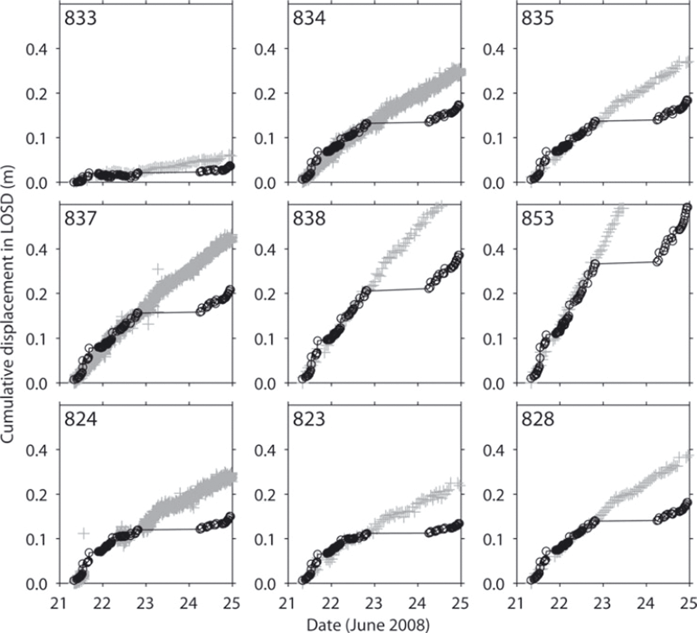
3.2.4. Cumulative displacements
The GPRI was operated almost continuously. We hence extracted the scalar displacements at the marker locations from the chain of 133 interferograms and plotted in Figures 5 and 6 the resulting cumulative displacements together with the marker displacement projected onto the LOSD. Note that in Figure 6 the observed displacements were extracted from the interferograms at the pixels closest to the marker positions. Cumulative observed and measured displacements are in good agreement. The observed displacements are offset by 1 day on 23 June due to the interruption of the GPRI operation on 23–24 June.
Cumulative observed (d*), black solid, circles) and measured (![]() , grey crosses) displacements in LOSD during 4 days (21–24 June) at nine (reference) markers.
, grey crosses) displacements in LOSD during 4 days (21–24 June) at nine (reference) markers.
Cumulative observed (d*, black solid circles) and measured (![]() , grey crosses) displacements in LOSD during 4 days (21–24 June) at the four markers 813–816 outside the GPRI scan sector. The observed displacements are extracted from the interferogram pixels nearest to the marker locations.
, grey crosses) displacements in LOSD during 4 days (21–24 June) at the four markers 813–816 outside the GPRI scan sector. The observed displacements are extracted from the interferogram pixels nearest to the marker locations.
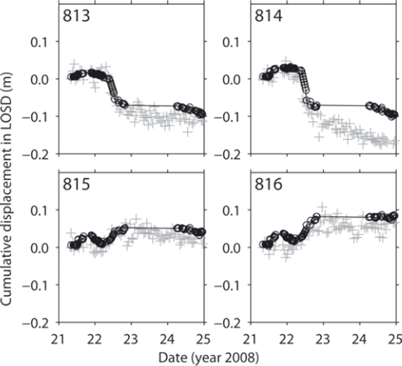
On 22 June, displacements decrease significantly at markers 813 and 814, while at markers 815 and 816 the displacements increase slightly (Fig. 6). This event is well captured by both GPRI and traditional marker measurements. It is the same signal as the displacement anomaly below the confluence, present in the displacement maps of Figure 3c and d, and the change of displacement has a magnitude of ∼10 cm within 0.5 day. This perturbation can be clearly captured by the GPRI.
4. Discussion
We have shown that the agreement between observed and measured displacements is associated with differences of ∼30%. The markers were located in the confluence region of Gornergletscher, which is the region where glacier flow is slowest and thus small displacements were recorded both by the GPRI and at the marker locations. We had been aware of the slow flow in the confluence, but expected more significant disturbances of the surface ice motion in the confluence and lake vicinity area (i.e. pronounced surface uplift as during the drainage event of 2004 (Reference Sugiyama, Bauder, Huss, Riesen and FunkSugiyama and others, 2008)). Small displacements occur because of the slow flow of Gornergletscher and the unspectacular influence of the lake drainage on the ice flow within the ice-dam/ confluence area of Gornergletscher. During 5–8 hours, the surface ice motion within the target area of Gornergletscher is a few cm at most. Thus, the actual measured displacements are on the order of the accuracy of the position estimation of the tachymeter and GPS for such a short time period. This explains why standard deviations are large and why the best agreement was observed where the largest displacement was measured.
The melt rates were on the order of 5 cm d−1. In fact, the large surface melt lowered the coherence of successive interferograms computed with >2 hours integration-time interval during daytime (afternoon). Thus, the 5 hour interferograms and displacement maps presented in Figure 3 were primarily obtained during evening and night time (except for the interferogram of Fig. 3b), when the melt was essentially absent and the inclusion of an ablation correction did not provide data enhancement. Therefore, we did not include any ablation correction when computing the displacements in LOSD from the measured displacements at the markers for comparison with the 5 hour GPRI displacements. On the other hand, for the computation of cumulative displacements like those shown in Figures 5 and 6, successive interferograms with time intervals of 20 min were computed, with good coherence also during daytime.
Below the confluence, the impact of the lake drainage was much more pronounced and resulted in displacements of the ice surface on the order of ∼10 cm within a few hours. The GPRI measurements in this area could not be directly compared with the in situ ice-displacement measurements as the GPRI scan sector did not overlap markers 813–816. Nonetheless, the agreement between cumulative displacements in LOSD extracted from the closest interferogram pixel to the measured marker displacement projected onto the LOSD is indeed satisfactory. The GPRI was clearly able to capture this perturbation both temporally and in spatial dimensions. The resulting displacement maps of Figure 3a–f provide detailed information on the spatial distribution of the displacement changes below the confluence, filling the information gap in the area between markers 823, 824 and 813–816.
4.1. Influence of Gornersee drainage on the surface ice motion
It is known that disturbances of the glacier’s subglacial environment by increased water input affect the basal motion of the glacier ice, which contributes substantially to the surface ice motion (Reference IkenIken 1981; Reference Iken and BindschadlerIken and others, 1986; Reference Sugiyama and GudmundssonSugiyama and Gudmundsson, 2004). The observed and measured changes in surface ice motion on Gornergletscher are thus most likely linked to changes in basal water pressure and temporary water storage in the subglacial drainage system, as induced by the drainage of Gornersee. It drained before the lake water level approached the level of flotation of the ice dam into one major subglacial channel. The impact of the lake drainage on the flow of Gornergletscher in the confluence/ice-dam area was minor; only a slight increase of displacement was determined, but surface uplifts or damaging of the lake border was not detected. This may indicate that the water traveled through the confluence area entirely englacially and only reached the glacier bed down-glacier of the confluence area, which is where the lake drainage had a very pronounced effect.
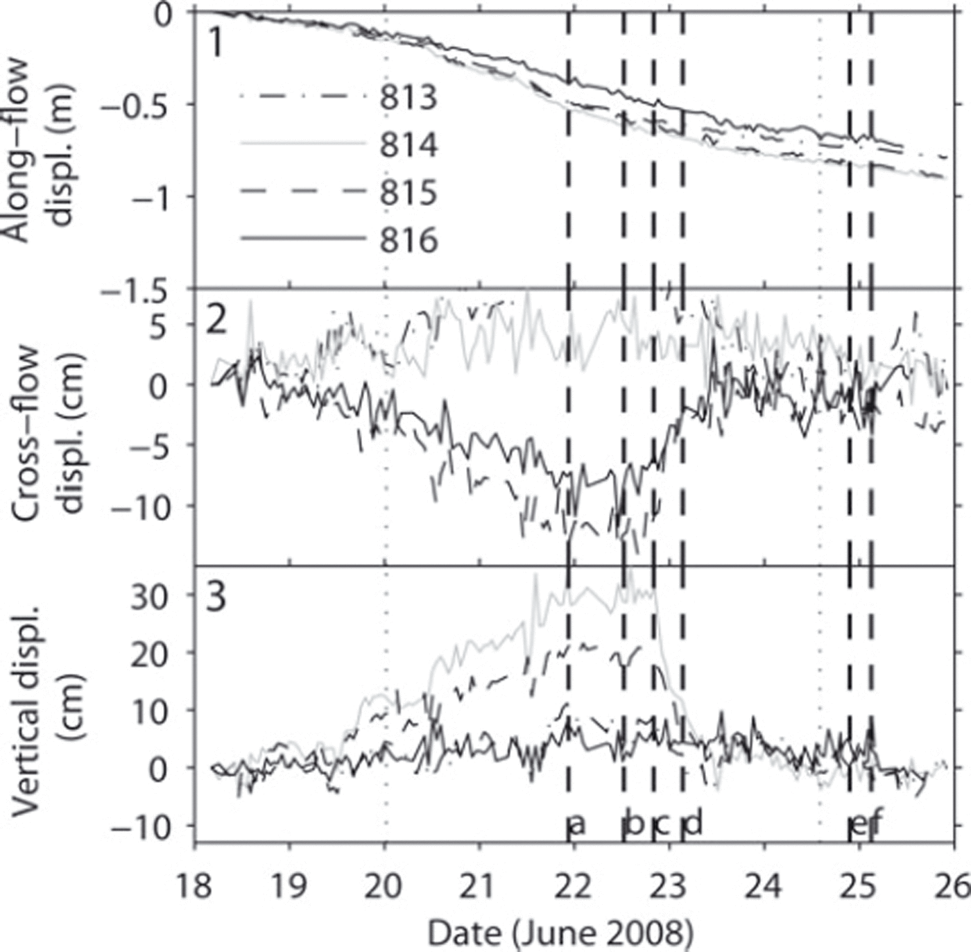
It is intriguing that the GPRI detected opposite displacements across Gornergletscher in the area below the confluence. To elucidate the observation of the GPRI, we refer to the displacements measured at the profile of markers 813–816 across Gornergletscher (Fig. 1b). In Figure 7 we plot the along-flow (1), cross-flow (2) and vertical (3) components of the displacement trajectories of markers 813–816. The along-flow direction of each marker refers to the mean flow direction at each marker. From 20 to 23 June, all markers moved slightly faster down-glacier (Fig. 7a). At the same time, markers 815 and 816 showed an excessive cross-flow excursive motion (southwards) of the order of 10 cm, while markers 813 and 814 seemed to move slightly in the opposite direction (northwards) (Fig. 7b). However, 815 and 816 do not move much in the vertical direction, while 813 and 814 show an uplift of almost 30 cm from 18 to 22 June (Fig. 7c). In the evening of 22 June, the vertical uplift of markers 813 and 814 drops significantly and the ice motion at markers 815 and 816 reverses to the opposite cross-flow direction (northwards), resuming its initial trajectory. This moment of contrariwise ice surface motion was recorded by the GPRI and is visible in the displacement maps recorded on 22 June (Fig. 3c and d). The anomalous signal recorded by the GPRI corresponds to the combined signal of surface down-drop (away from the GPRI, resulting in negative displacements) and cross-flow motion (towards the GPRI, resulting in positive displacements) in the radar look direction across the lower tongue of Gornergletscher, the moraine M2 separating these two motion events. The origin of this anomalous ice motion is not clear. It is treated in detail by Reference Sugiyama, Bauder, Riesen and FunkSugiyama and others (2010).
Displacements (displ.) along (1) the mean ice-flow direction, (2) the cross-flow direction, and in (3) the vertical direction, at markers 813–816. The dashed vertical lines a–f correspond to the start times of the interferograms given in Figure 3.
5. Conclusions
We successfully measured the surface ice motion of Gornergletscher during the drainage of the adjacent Gornersee using a real aperture radar interferometer, GPRI. The lake drainage induced local variations in the ice surface motion of Gornergletscher. We successfully detected the ice displacement variations with the GPRI. The agreement with local in situ ice displacement measurements is satisfactory and shows that the GPRI produces reliable results. It is suitable for measuring ice displacement variations over a large area and over short timescales of a day to a few hours. In the Gornergletscher confluence area, the ice motion anomaly traveled at lowest velocities, on the order of 0.1 m d−1. This is about the lower limit of velocity at which an ice motion event can be tracked with an acceptable error of ∼10%. Our study showed the approximate lower resolution limit of the GPRI. Nevertheless, the range of application is wide. Perturbations of the ice motion which produce displacements and travel at speeds higher than 0.1 m d−1 can be tracked by the GPRI with high accuracy on the sub-daily scale. An upper limit of travel speed is given by the range/ azimuth resolution, i.e ∼50 m d−1. This (theoretical) upper limit is influenced by the loss of coherence due to ablation and should be assessed by further field measurements.
Acknowledgements
This research was funded by Swiss National Science Foundation grants 200021-103882/1 and 200020-111892/ 1. We are grateful to the International Foundation High Altitude Research Stations Jungfraujoch and Gornergrat (HFSJG) for providing facilities and support. We thank C. Werner and U. Wegmüller from GRS for support with using the GPRI device. We appreciate the support and helpful comments of F. Walter, K. Hutter, of the scientific editor, T.H. Jacka, and an anonymous reviewer. Thanks are also extended to all members of the 2008 field campaign on Gornergletscher.


