

Introduction
Metre-thick layers of potassium–magnesium (K–Mg) salts are common in salt giants like the European Zechstein or the Cretaceous of offshore Brazil (Cerqueira et al., Reference Cerqueira, Chaves, Pessoa, Monteiro, Pereira and Wanderley1997; Geluk et al., Reference Geluk, Röhling, Brückner-Röhling and Geertman2000, Reference Geluk, Paar, Fokker, Wong, Batjes and De Jager2007; Warren, Reference Warren2006). Consisting of carnallite or sylvite, these layers are locally exploited by potash mining. They are also known to generate problems while drilling subsalt wells, caused by their high solubilities and very low viscosities (Williamson et al., Reference Williamson, Murray, Hamilton and Copland1998). Occasionally, even less viscous layers of tachyhydrite or bischofite are included in this sequence (Coelewij et al., Reference Coelewij, Haug and Van Kuijk1978; Vysotskiy & Kislik, Reference Vysotskiy and Kislik1987; Poiate et al., Reference Poiate, Costa, Falcao and Petrobrás2006; Geluk et al., Reference Geluk, Paar, Fokker, Wong, Batjes and De Jager2007).
The K–Mg salts carnallite and bischofite deform in the laboratory with viscosities up to three orders of magnitude lower than halite (Van Eekelen et al., Reference Van Eekelen, Urai and Hulsebos1981; Spiers et al., Reference Spiers, Urai, Lister, Boland and Zwart1983; Urai, Reference Urai1983, Reference Urai1985; Urai & Boland, Reference Urai and Boland1985; Langbein, Reference Langbein and Peryt1987; Urai et al., Reference Urai, Spiers, Peach, Franssen and Liezenberg1987, Reference Urai, Schléder, Spiers, Kukla, Lange and Röhling2008; Scott Duncan & Lajtai, Reference Scott Duncan and Lajtai1993; Schenk & Urai, Reference Schenk and Urai2005; Muhammad, Reference Muhammad2015). Together with the much stronger carbonates and sulphates that are precipitated in the same evaporation cycle, a highly stratified mechanical layering can develop inside salt bodies (Richter-Bernburg, Reference Richter-Bernburg, Lerche and O´Brien1987; Geluk, Reference Geluk1998, Reference Geluk and Geertman2000; Warren, Reference Warren2006; Bérest et al., Reference Bérest, Ghoreychi, Hadj- Hassen and Tijani2012). During deformation, evaporites form complex structures including folds, faults, veins and breccias that are often visible in mine galleries and drill cores (Martini, Reference Martini1953; Roth, Reference Roth1968; Siemeister, Reference Siemeister1969; Coelewij et al., Reference Coelewij, Haug and Van Kuijk1978; Talbot et al., Reference Talbot, Tully and Woods1982; Richter-Bernburg, Reference Richter-Bernburg, Lerche and O´Brien1987; Jackson & Talbot, Reference Jackson and Talbot1989; Bornemann & Fischbeck, Reference Bornemann and Fischbeck1991; Burliga, Reference Burliga1996; Zirngast, Reference Zirngast1996; Behlau & Mingerzahn, Reference Behlau and Mingerzahn2001; et al.Bornemann et al., Reference Bornemann, Behlau, Fischbeck, Hammer, Jaritz, Keller, Mingerzahn and Schramm2008; Schléder et al., Reference Schléder, Urai, Nollet and Hilgers2008; Hammer et al., Reference Hammer, Behlau, Mingerzahn and Mertineit2014). However, there are no mine galleries and very few drill cores in evaporites rich in bischofite, due to mechanical and chemical instability. Although mine and core observations give excellent insights into the structures and deformation processes present, the full internal structure of the salt bodies can only be extrapolated from these limited data.
While the external morphology of salt bodies is relatively well understood and can be imaged using 3D reflection seismic data, internal structures in 3D have only recently begun to be studied, using internal reflectors with high acoustic impedance contrasts (anhydrite + carbonate stringers) (Van Gent et al., Reference Van Gent, Urai and De Keijzer2011; Cartwright et al., Reference Cartwright, Jackson, Dooley and Higgins2012; Fiduk & Rowan, Reference Fiduk and Rowan2012; Jackson et al., Reference Jackson, Jackson, Hudec and Rodriguez2014, Reference Jackson, Jackson, Hudec and Rodriguez2015; Strozyk et al., Reference Strozyk, Urai, Van Gent, De Keijzer and Kukla2014). A recent study (Raith et al., Reference Raith, Strozyk, Visser and Urai2016) using high-resolution 3D seismic data, described the large-scale structure of the K–Mg salt-rich Zechstein 3, inside the Veendam salt pillow in the north European Zechstein basin. Nevertheless, the spatial resolution of 3D reflection seismic is limited and structures smaller than 25–30 m cannot be imaged.
In this project, we analysed 81 m of core drilled through the K–Mg salt-rich Zechstein III-1b subunit in the Veendam Pillow. This combination of 3D seismic and a drill core provides a unique opportunity to study the deformation of a salt body with extreme rheological layering at km to 0.1 mm scales, over six orders of magnitude. The core was analysed with the aid of chemical analyses, X-ray diffraction (XRD) and optical microscopy.
The following two questions are addressed: (1) how is strain partitioned in a salt body with extreme rheological layering? and (2) does strain partitioning result in strongly deformed but continuous layers or do pinches or fractures disrupt the original layering to produce a tectonic mélange?
Our results can help us to better understand the impact of thin soft layers on the behaviour of a deforming salt body and to improve prediction of the geometries of ore bodies made up of K–Mg salts. The results of this study may help us to improve the understanding of well-bore stability in K–Mg salts and to predict the long-term evolution of abandoned solution-mining caverns and nuclear waste repositories.
Study area
The Tripscompagnie 9 (Tr-9) core was drilled in the SE flank of the Veendam salt pillow 10 km southeast of the city of Groningen in the NE Netherlands (Fig. 1a). The Veendam Pillow is located at the southernmost edge of the Groningen High in the Lower Permian Basin. The Southern Permian Basin has undergone four tectonic phases with extension, compression and halokinesis (Ziegler, Reference Ziegler1978; Mohr et al., Reference Mohr, Kukla, Urai and Bresser2005; De Jager, Reference De Jager, Wong, Batjes and De Jager2007; Geluk et al., Reference Geluk, Paar, Fokker, Wong, Batjes and De Jager2007). Three major tectonic phases (break-up of Pangaea in the Mesozoic, the Alpine inversion in the late Cretaceous and Early Tertiary and the Rhine Graben rift development from the Oligocene to recent times) took place after salt deposition and triggered renewed salt movement. The Zechstein section in the Veendam Pillow contains Z-I to Z-IV overlain by Lower Triassic (Buntsandstein and upper Röt), Cretaceous (Rijnland and Chalk), Tertiary units (Lower/Middle and Upper North Sea Group) and the Quaternary (Raith et al., Reference Raith, Strozyk, Visser and Urai2016) with an important erosional unconformity between the Triassic and the base of the Cretaceous.
(a) Depth map of Top Salt at the Veendam Pillow. The TR9 well (red dot) was drilled at the SE flank. The profile A–Aʹ is shown in (b). (b) E–W profile (A–Aʹ) at the core location from seismic interpretation (Raith et al., Reference Raith, Strozyk, Visser and Urai2016).
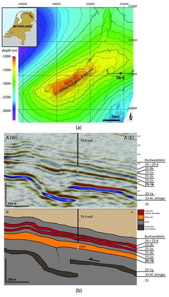
The focus of this study is on the Z3 unit, which contains the Zechstein 3 anhydrite–carbonate (Z3-AC) layer (also called Z3 AC stringer or floater since it is a distinct reflector in the typically seismically transparent rock salt) at the base, overlain by four Z3 subunits (Fig.1b). The Z3 subunits typically consist of halite (>95%) in the lower part (Z3-1a,2a,3a) followed by a K–Mg salt part (Z3-1b,2b,3b) (Geluk et al., Reference Geluk, Paar, Fokker, Wong, Batjes and De Jager2007). The Z3-4 contains no K–Mg salt. While the K–Mg salts in the Z3-2b and -3b were interpreted as intimate mixing of carnallite and halite crystals as the result of co-precipitation (Coelewij et al., Reference Coelewij, Haug and Van Kuijk1978), the much thicker Z3-1b consists of numerous thin layers dominated by one mineral type and metre-thick layers of bischofite. The massive occurrence of bischofite was interpreted as being the result of accumulation of bittern brines in a local depression formed by an active graben in the subsalt Rotliegend (Raith et al., Reference Raith, Strozyk, Visser and Urai2016).
Corresponding to the regional development, salt flow in the Veendam Pillow can be divided into three main phases (Raith et al., Reference Raith, Strozyk, Visser and Urai2016): (1) early extensional salt flow during the Triassic and Jurassic leading to the break-up of the 3Z3-AC stringer, (2) a tectonically quiet phase that lasted until the early Late Cretaceous, and (3) onset of the basin inversion during the late Cretaceous that led to overburden buckling and downbuilding of sediments around the Veendam Pillow forming the structure present today. The salt flow was convergent towards the pillow centre, causing folding and thrusting of the competent Z3-AC stringer. This folding had a dominant influence on the overlying soft K–Mg salts, which were concentrated into areas above the stringer synclines (Raith et al., Reference Raith, Strozyk, Visser and Urai2016). This deformation history suggests intense lateral salt flow in the Z3-1b with high strain, complex folding and boudinage, although in the core photos of Coelewij et al. (Reference Coelewij, Haug and Van Kuijk1978) this is not readily visible.
Data and methods
The Tr9 well was cored over 81 m in December 2012 starting at a 1781.25 m true vertical depth (TVD) (drillers depth of 2420 m). The drilling itself and the first processing of the cores was part of the magnesium-salt exploration of Nedmag B.V. and not part of this research project focusing on the internal deformation of soft K–Mg salts. The core was described on site (ECOSPLAN), and one-quarter of the core (parallel to core axis) was cut out for chemical analysis of 20–40 cm long pieces which were dissolved and analysed for K, Na, Mg, Ca and S content using ICP-MS (inductively coupled plasma--mass spectrometry) (Appendix 1 in Supplementary Material at https://doi.org/10.1017/njg.2017.31). In this paper, we always quote TVD.
For further analysis, 2 cm thick slabs were cut (parallel to core axis) using a diamond saw blade and a small amount of saturated Na, Mg and K chloride brine for cooling and cleaning the diamond blade. We note that when cutting the core, the 1 m core segments were unfortunately not marked to allow orienting the segments with respect to north. When preparing for slabbing, the core segments were matched as well as possible. This was complicated by fact that the quarter of the core that was extracted directly after drilling was cut randomly and the slabs had to be aligned with the existing cuts to produce continuous pieces from the centre of the core axis. Hence, the slabs and photos shown do not always match in orientation, and therefore dip directions are random. As a result, it is not possible to recognise folds directly by change of dip angle if the fold wavelength exceeds the core segment length of about 1 m.
The core slabs were photographed using reflected and transmitted light and subsequently stitched together to images with a resolution of about 250 pixels per cm (Fig. 2). The pictures were taken under constant artificial light conditions to be able to compare colours and identify grain boundaries. The work on the core was carried out in a dry laboratory with a constant relative humidity under 15%. Under these conditions thin sections containing soft and hygroscopic salts like bischofite can be prepared using dry sanding paper with incremental grit sizes from 300 to 4000. During the grinding of bischofite, the top few µm of the polished surface immediately recrystallised; this fine-grained recrystallised layer was removed in a last step with a slightly damp polishing cloth as described in Urai (Reference Urai1983).
Photographed TR-9 core slabs in transmitted and reflected light together with the interpretation into lithoclasses. Each core piece is numbered starting at the highest, first cored part. Missing core pieces are marked with blank panels.

After the first round of analyses, the core was subdivided into six main lithoclasses with additional subcategories, defined by mineralogy and microstructure as recognizable with a hand lens. Thin sections and XRD analysis were used to determine the exact mineralogical composition of the lithoclasses. Detailed analysis of the microtextures in the thin sections was carried out using transmitted and reflected light polarisation microscopy. After gathering the data, the structures in the core were interpreted by identifying layer repetition, folding, faults, veins and fractures. Additionally, polished sections from halite-dominated samples were etched with a slightly under-saturated NaCl brine for about 30 s and dried using a jet of n-hexane to remove all brine. The etching makes halite subgrain boundaries visible in reflective light microscopy, and the halite subgrain sizes were used for halite subgrain piezometry (Carter et al., Reference Carter, Horseman, Russell and Handin1993; Franssen, Reference Franssen1993; Schléder & Urai, Reference Schléder and Urai2005).
Results
Lithoclasses
The layers in the core can be divided into five main lithoclasses (see below) based on the dominant evaporite mineral. These lithoclasses are briefly described below and can be subdivided into subcategories consisting of mixtures.
Halite (NaCl)
Almost pure halite is only present in the top few metres of the Z3-1b and in the Z3-1a cycles. In most cases, halite is mixed with kieserite and in some cases with carnallite. The halite at the top of 1b (under the 1.5 m thick breccia of halite in a carnallite matrix in the top) is divided in equiaxial very coarse-grained (up to 3 cm) layers and layers with <1 cm grain sizes (Fig. 3). In contrast to the rest of the Z3-1b a small amount of clay is common; there is no kieserite present. The coarse halite grains contain subgrains with an average size around 300 µm (Fig. 4). In some grains, chevron-shaped parallel bands of fluid inclusions are present. These have been interpreted as of primary fluid inclusions (Schléder & Urai, Reference Schléder and Urai2005).
Detailed pictures of core piece 1785.7–1786.1 m TVD in transmitted and reflected light showing large, >3 cm, equiaxial halite crystals.

(a) Polished section from top C_H-3 halite showing subgrains inside one big crystal with parallel straight fractures most likely originated from coring or sample preparation. (b) Example of parallel fluid inclusion lines, interpreted to be primary fluid inclusions built into the crystal during evaporation.

The grey to light-brown halite in the Z3-1a contains layers of 5–40 cm thickness separated by thin (few mm) folded or boudinaged layers of fine-grained sulphates (Fig. 5). The up to 5 mm diameter equiaxed halite grains with 120° triple junctions of grain boundaries contain occasional subgrains of about 180 µm size.
Example of the Z3-1a halite. The halite layers are frequently interrupted by thin sulphate layers. The detailed pictures (a, b) show thin layers of slightly folded polyhalite and kieserite. (right) Reflected light microscopy pictures of an edged section showing halite grains of sizes up to several mm and one halite grain (red dashed line) containing subgrains <200 µm. The banding of the halite is very unclear and not distinguishable on this figure.

In the Z3-1b subunit, halite is commonly interbedded with kieserite, forming Halite + Kieserite layers (Figs 6, 7). The grey to white halite–kieserite layers are typically thin-layered and appear in layers from 1 to 30 cm thickness. The sub-mm elongated halite grains (Figs 6, 7) are mixed with kieserite and small amounts of other salts and sulphates. Commonly, these layers are fractured with carnallite/bischofite veins or are separated into fragments in a matrix of carnallite or bischofite. Thin separated halite/kieserite layers are often folded. In thin sections (Figs 6, 7), a distinct elongation of the halite crystals parallel to bedding can be observed. Halite grain size tends to decrease with increasing kieserite content. The halite grains show an aspect ratio of about 3 : 1 and are on average 250 µm long and about 80 µm in the short axis. The kieserite grains are smaller than 20 µm and mostly euhedral (Figs 7, 8).
Slab photographs and thin section of a halite–kieserite mix. Elongated (1 : 2–1 : 3) halite crystals smaller than 0.2 mm (long axis). Intra- and inter-crystalline kieserite is present. The kieserite content varies, forming a parallel layer of higher concentration or complete kieserite layers <0.5 mm. The halite grains are smaller in the layers of higher kieserite concentration. Carnallite is present in sparse layer-parallel lenses with irregular, often elongated (1 : 4), crystals up to 1 cm in size.

Slab photographs and thin section of the contact between a halite + kieserite (top) and carnallite (bottom) layer. Colour code for the lithologies is given in Figure 2.

Examples of kieserite in thin sections. (a) Bischofite and carnallite mixed layer with intra-crystalline kieserite marking old grain boundaries (red arrows). (b) Kieserite overgrown by one larger carnallite crystal. (c) Bischofite, carnallite and kieserite mixed vein in a hostrock of kieserite halite and carnallite. (d) Halite–kieserite mix in cross-polarised (XPL) and unpolarised (PPL) light. (e) Intra-crystalline kieserite in carnallite marking the outline of a recrystallised grain. (f) Kieserite tracks in carnallite crystals shown in XPL (red dashed line).

In some layers halite or halite and kieserite is mixed with larger amounts of carnallite forming Halite + Carnallite and Halite + Carnallite + Kieserite layers. These layers have a grey to white colour and are less transparent than the Halite + Kieserite layers.
Kieserite (MgSo4*H2O)
Although kieserite layers in halite are common in the core, they are normally so thin (<50 µm) that they are mostly included in the Halite + Kieserite or Kieserite + Halite lithoclass, depending on the dominant mineral. The thin kieserite-dominated layers can easily be identified on the freshly cut core surface due to their lower solubility compared to the surrounding salts.
Small amounts of kieserite (<10%) are present in almost all layers as small (10–200 µm) euhedral crystals representing about 5% of the core. Intra- and intergranular kieserite makes up to 7% of the bischofite- or carnallite-dominated layers (Fig. 8). It is also present in mixtures with bischofite where it can make up <50% of the mixture forming thin (few cm) Kieserite + Bischofite layers.
Carnallite (KMgCl3*6H2O)
Carnallite is common in the Z3-1b part of the core (24 vol.% based on the chemical analyses) in up to 1.5 m thick layers consisting of up to 2 cm diameter elongated grains with wavy to straight grain boundaries and 120° triple points between grain boundaries (Figs 7, 9). Many grains show (110) oriented twin lamellae (Tröger et al., Reference Tröger, Bambauer, Taborszky and Trochim1982) and subgrains are rare. Wavy grain boundaries are common, indicating grain boundary migration recrystallisation (GBM). Minor clusters of kieserite are present inside the grains and on the grain boundaries, while intra-crystalline inclusion trails of kieserite often mimic the structure of old grain boundaries (ghost grain boundaries; Fig. 8, cf. Urai and Boland, Reference Urai and Boland1985). Clusters of rounded halite grains of up to 1 mm are often found between the carnallite grains. The carnallite is commonly transparent, grey to white except in the top (Fig. 2a: 1781–1784 m TVD) where it is red. Red carnallite from the Veendam Pillow has been studied by Urai and Boland (Reference Urai and Boland1985) and they found the red colour is caused by dislocation networks decorated by hematite. These hematite networks were not present in the samples studied here.
Slab photographs and thin section of a typical carnallite layer in the TR-9 core. In these layers, up to 1.5 cm partly elongated carnallite grains with mostly straight GBs. 120° triple points are common. Intra- and inter-crystalline kieserite is present (scattered and ghost grain boundaries). Halite is present, often in small clusters of rounded grains <1 mm. Colour code for the lithologies is given in Figure 2.

Carnallite is also present in mixed Carnallite + Halite + Kieserite and Carnallite + Kieserite + Bischofite layers. Here the carnallite is present in small <2 mm grains elongated parallel to the layering or as large amoeboid grains overgrowing kieserite. In veins, equiaxed carnallite is often mixed with equiaxed bischofite of similar grain size (<1 cm) and inter- and intra-crystalline euhedral kieserite (Fig. 12c).
Bischofite (MgCl2*6H2O)
Bischofite forms massive 5–8 m thick layers in the centre of the Z3-1b. These layers contain less than 20% other phases with up to 10 cm sized broken fragments of fine-grained, layered rock salt or single halite and carnallite grains inside the bischofite matrix (Fig. 10). Fine-grained equiaxed intra- and intergranular kieserite is commonly present. The bischofite grains are elongated, typically 2–5 cm in size, and some of the bischofite grains can grow to >15 cm. The grain texture shows frequent 120° grain boundary triple points and wavy grain boundaries. In some cases, GBM and grain overgrowths can be observed. While subgrains are very scarce, (110) twin lamellae are common, possibly caused by thin-section preparation. The bischofite layers are very similar to the carnallite layers in texture but have larger grain sizes and are more transparent. If small amounts of halite are mixed with bischofite the halite grains are rounded and accumulated in small clusters. In some layers bischofite is intergrown with carnallite, forming Bischofite + Carnallite (± Kieserite) layers that have a similar texture to the pure carnallite and bischofite layers.
Slab photographs and thin section of a typical bischofite layer. Up to 2 cm elongated bischofite grains with wavy grain boundaries and 120° triple points. Kieserite on grain boundaries and inside grains (scattered and ghost grain boundaries). Very small amount of <0.5 mm halite grains.

Sulphate mineral layers (XSO4)
Beside kieserite, which is almost omnipresent in small quantities in the core, other sulphates forming mixed layers are also present. All layers dominated by sulphates beside kieserite (polyhalite, anhydrite, kieserite) are grouped into this lithoclass. These layers are only present in the top Z3-1a part of the core and are typically opaque, white to grey. Besides kieserite, polyhalite forming thin (up to 10 mm) layers and anhydrite as rare single <1 mm crystals are present.
Structure of the core
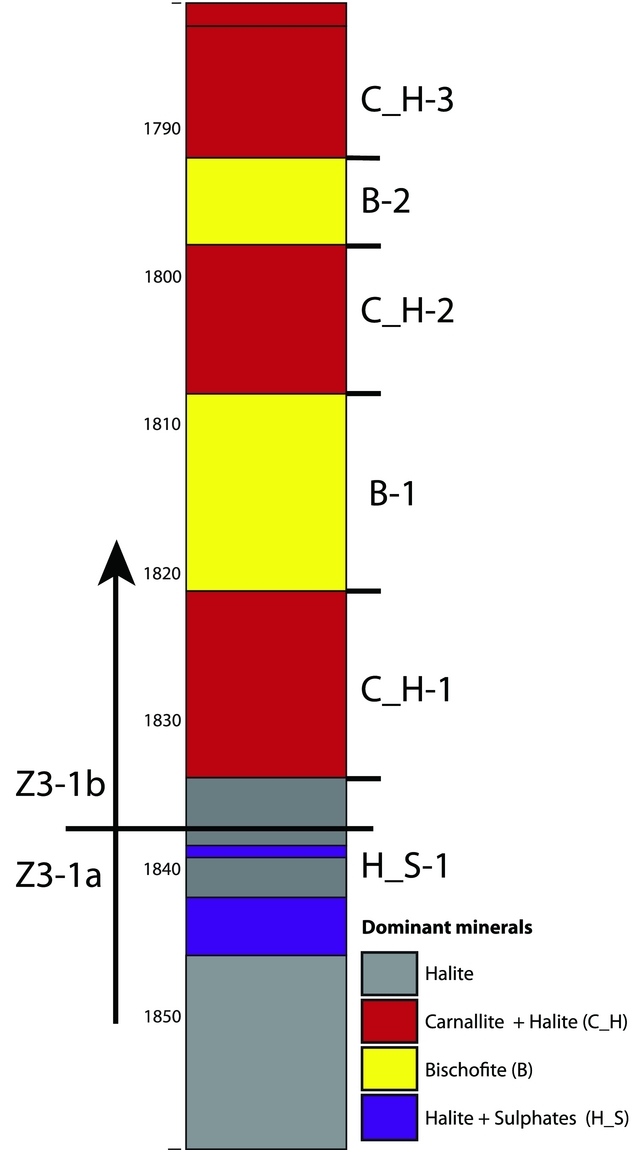
The 81 m long TR9 core represents almost the entire Z3-1b subunit (from 1781.25 to 1837 m TVD) with the top 22 m of the Z3-1a (from 1837 to 1859.37 m TVD). While the Z3-1a mainly consists of halite (>95%) with thin (up to 1 cm layers) of sulphate minerals, the Z3-1b is dominated by K–Mg salts: interbedded, dm-scale halite–carnallite layers with minor kieserite and two massive (7 and 15 m thick) bischofite layers (Fig. 11). In what follows we describe the structure of the core, from top to bottom, divided into sections of similar composition and structure. An overview of these results is given in Table 1.
Overview of the different layers in the TR-9 core.
Overview of the Z3-1b in the core studied

Carnallite/Halite 3 (C_H-3) (1781.25–1792 m TVD)
The top of the core consists of a 1.6 m thick layer with cm-sized fragments of fine-layered rock salt in a matrix of red carnallite with bischofite (Fig. 2a: 1781–1782.6 m TVD). This is followed by 0.7 m of coarse-grained rock salt and 0.7 m of interbedded cm-scale layers of halite and carnallite (Fig. 2a: 1782.6–1783.9). Unlike the deeper parts of the core a small amount of clay gives the top part a much darker colour. The lower part of this section (Fig.2a: 1785.3–1792 m TVD) shows a gradual change from halite to K–Mg salts and increasing layer thickness. The top 3 m consists of alternating bands of fine- and coarse-grained halite with minor clay (Fig. 2a: 1784–1787.6 m TVD). The clay content decreases with depth, and no clay is visible after 3.5 m. This is where the first thin carnallite and halite–kieserite mix layers appear. With increasing depth, the carnallite and kieserite mix layers become thicker, reaching up to 30 cm thickness (Fig. 2a: 1791.2 m TVD). In the last metre (Fig. 2a: 1790.9–1791.8 m TVD) of this part, bischofite is present in the carnallite-dominated layers and in veins perpendicular to bedding.
Bischofite 2 (B-2) (1792–1798 m TVD)
The upper bischofite section consists of very coarse-grained (1–3 cm diameter) bischofite with some grains larger than 10 cm (Fig. 2c: 1810.3 and 1811.8 m TVD). Minor halite and carnallite (up to 5%) are mostly present in clasts of 1–30 cm. These clasts range from rounded to angular, and contain fine-grained layered kieserite. They are locally boudinaged and contain veins filled with bischofite, carnallite and kieserite (Fig. 2b: 1796–1796.6 m TVD).
Carnallite/Halite 2 (C_H-2) (1798–1808 m TVD)
The top 1.5 m of this part consists of fragments of layered kieseritic rock salt in a matrix of carnallite and occasionally bischofite. This is followed by 3.5 m of 10–30 cm thick halite and halite/kieserite layers interbedded with carnallite forming metre-scale folds (Fig. 12 FZ-1). The fold axial planes are sub-horizontal and about 1–1.5 m from each other (Fig. 12). In the fold cores, faulting of the kieseritic rock salt layers is common (Fig. 2b: 1801.2 m TVD). This folded area is followed by 0.7 m of broken kieseritic rock salt fragments (<10 cm), in a matrix of bischofite.
Detailed view on the structure of C_H-2 showing a typical tectonic breccia of halite + kieserite fragments inside a bischofite matrix and an example of layer correlation in a folded segment (FZ-3). The three examples show the same layer sequence while #2 is overturned. Unlike most parts of the core, the core pieces in the C-H-2 part could be aligned reasonably well using the whole core pieces. The structural interpretation was performed using the whole core. Thus, the slabbed core pieces in this figure show only part of the available information and visible dips can be misleading.

This is followed by 2 m of a recumbent fold (Fig. 12 FZ-2) with bischofite in the core (Fig. 2c: 1804.7 m TVD), and interbedded kieseritic rock salt and carnallite at the flanks on top and above the fold are cut off by a sub-horizontal discontinuity, followed by 3 m of folded kieseritic halite layers (Fig. 12 FZ-3) interbedded with carnallite (layer thickness 10–40 cm). The fold axial planes are sub-horizontal and about 1.5 m from each other (Fig. 12).
Bischofite 1 (B-1) (1808–1821.8 m TVD)
This 15 m bischofite- (90%) rich part of the core is similar to B-2 but with less kieseritic rock salt. It contains a 1.5 m thick layer of coarse-grained (1–2 cm) carnallite (Fig. 2c, d: 1815.7–1817.3 m TVD). No layering can be observed in the bischofite and carnallite sections, while the enclosed halite/kieserite fragments are fine-layered or cloudy.
Carnallite/Halite 1 (C_H-1) (1821.8–1834.7 m TVD)
The lowest part of the Z3-1b consists of 13 m folded and broken interbedded halite carnallite layers. Folding is present at mm to metre scale interrupted by common fracturing and highly deformed zones. In contrast to the C_H-2 layer, only minor bischofite is present in this part and no fragments in a carnallite or bischofite matrix were observed.
Halite/Sulphate 1 (H/S-1) (1834.7–1839.3 m TVD)
The halite-rich part at the top of the Z3-1a starts with 4.5 m of folded halite with 0.5–2 cm thick carnallite and sulphate mineral (kieserite, polyhalite, anhydrite)-rich layers. This halite-dominated part is followed by 7 m of halite with much higher sulphate mineral content and some boudinaged and faulted sylvite layers.
Halite (1839.3–1859.4 m TVD)
In the bottom part of the core the Z3-1a consists of halite layers with mm-scale folded sulphate (polyhalite, kieserite, anhydrite) and sylvite layers every 20–50 cm separating the halite layers (Fig. 5). The halite is slightly banded by different grain sizes of 0.5–1 mm in the coarse and <0.5 mm in the fine domain with unclear transitions.
Deformation structures
Visible macro-scale structures in the core are present in small halite/kieserite layers or at larger scale in the interbedded halite–carnallite layers. The common structures are folds, fragments of layered kieseritic rock salt in a matrix of carnallite or bischofite and veins in kieseritic rock salt layers.
Folds
Folds at different scales are interpreted to be common in the Z3-1b. Folding can only be observed if layering was originally present and preserved during deformation (Hirsinger & Hobbs, Reference Hirsinger and Hobbs1983). This is the case in the C_H-1 & 2 layers where metre-scale recumbent folding is interpreted by the closure in the core with correlation of layers on both limbs (Fig. 12). In C_H-2, faulting can be observed in the fold centres and at the hinges. The thickness of the carnallite layers interbedded with halite varies and sometimes the carnallite is completely absent between two corresponding halite layers (Fig. 12). Since the core can only provide 1D information, folds were identified by tracing distinct layer sequences that were found in upright and reversed order (see example in Fig. 12) that sometimes had well-preserved fold cores in the middle (see a fold core at 1806.2–1806.4 m TVD; Fig. 2c).
Folds in the C_H-1 are present on metre to cm scale. The observed fold axes are mostly sub-horizontal with a variety of axial planes from horizontal to vertical. Some observed folds have curved axial planes (Fig. 2d: 1824–1825 m TVD). Coherently folded sections of the core can rarely be traced over more than a few metres, when discontinuities (shear-zones or faults) interrupt the layering (Fig. 12).
In bischofite- and carnallite-dominated layers, folded thin (<3 cm) halite/kieserite layers also show sub-horizontal fold axis but no preferred orientation of the axial planes.
Boudinage, veins and tectonic fragmentation
Halite and kieserite layers are frequently fractured. The fragments are either completely separated as fragments in a matrix of carnallite and bischofite or contain thin, up to 1 cm wide, veins which separate the boudins. These veins are filled with bischofite + kieserite, carnallite + kieserite or both and appear as bedding-parallel and bedding sub-normal veins. The veins at high angle to bedding are commonly observed in halite- or kieserite-rich layers interbedded with K–Mg salts and are often quite high in kieserite content.
Discussion
Sedimentation and diagenesis
The Z3-1b represents the last stage of evaporation of seawater and is interpreted to have been deposited over numerous minor evaporation–refreshing events in the 1b sub-cycle. In the parts of the core where the original layering was not overprinted by high strain deformation, the core consists of thin usually monomineralic beds. This kind of texture is typical for shallow water precipitation (Coelewij et al., Reference Coelewij, Haug and Van Kuijk1978). Changing conditions in temperature and composition of the brine by refreshing events lead to a switch in precipitation of one dominant phase. This is particularly clear in the C_H layers with alternating beds of halite and carnallite. Every halite layer could represent a minor refreshing event, raising the Na content of the brine (Borchert & Muir, Reference Borchert, Muir and Van1964). The thin kieserite-enriched layers inside halite layers, on the other hand, can be interpreted as the result of annual temperature changes due to their mm-spaced periodic character and the thermophile precipitation of kieserite. The kieserite was either precipitated directly or was the result of a later metamorphosis from epsomite. For direct precipitation of kieserite, very high temperatures >55°C are necessary (Borchert & Muir, Reference Borchert, Muir and Van1964). Although those high precipitation temperatures are rarely observed in other evaporite bodies, the unique abundance of massive bischofite layers in the core indicates precipitation from shallow, hot brine pools during Z3-1b time.
Most layers show sharp contacts to other lithologies, and gradual transitions are rarely present on the cm scale. However, as shown below, primary gradual transitions could have been overprinted by layer-parallel shearing concentrated in the softer layers.
Beside the numerous minor refreshing events, two major events are interpreted (Fig. 13). Those events caused a change in precipitation from Mg-rich to halite-rich salt while preventing full dissolution of the underlying bischofite layers. These events are present at the B-1/C_H-2 and B-2/C_H-3 contacts. While the B-1/C_H-2 is rather sharp, the B-2/C_H-3 contact is a gradual transition from pure bischofite to pure halite over 5 m vertical distance.
Core overview showing the precipitation zones (after Pohl, Reference Pohl2011) and bischofite content (from ICP analysis). Starting from the 1a halite, the 1b composition slowly develops from sulphate-rich halite (S_H-1) to an interbedding of carnallite with halite (C_H-1). Towards the top of the C_H-1 layer, the carnallite content increases and first bischofite crystals appear inside the carnallite layers. At a depth of 1822 m the composition changes to strongly bischofite-dominated, ending the evaporation sequence in the B-1. Thin halite/kieserite layers and the 1.5 m of carnallite in the middle of the B-1 indicate refreshing events bringing in new sodium and sulphate. At the contact to the overlaying C_H-2 at a depth of 1808 m the composition changes to an interlayering of halite with carnallite, which is interrupted by two bischofite-rich layers at a depth of 1805 and 1802.5 m. The C_H-2 is interpreted to represent a refreshing event bringing the precipitation back into the carnallite zone. Towards the top of the C_H-2 the carnallite content increases and the transition to the B-2 is gradual from carnallite-dominated to bischofite-dominated at a depth of 1797.5 m. The B-2 bischofite is not as pure as the B-1, with more fragments of broken kieserite/halite layers. At the C_H-3 contact at 1791.8 m depth, 10–20 cm thick halite layers appear that are interbedded with bischofite, carnallite and kieserite layers. The thickness and bischofite content of these layers gradually decreases towards the top until pure halite is present from 1787.5 to 1784.1 m. In the top 2 m a gradual increase of bischofite (up to 30%) and carnallite (20%) is present. Here bischofite and carnallite form the matrix of a breccia with halite clasts. TR9 log data indicate that the following 5 m above the core are still rich in carnallite and bischofite until pure halite is reached at a depth of 1776 m.

In many locations across Europe, Z3 K–Mg salt deposits show mineral alterations during metamorphosis, caused by the dewatering of gypsum in the underlying Z3-AC stringer (Borchert & Muir, Reference Borchert, Muir and Van1964). The result of this process is the rise of Na-chloride and sulphate-rich brines forming ‘Hartsalz’ (sylvinitic halite + sulphates) deposits when they come into contact with carnallite. In the TR-9 core Hartsalz is not present in Z3-1b. That does not mean that the usual gypsum–anhydrite transition did not take place, but we see no evidence for interaction with the fluids (30% vol. loss) in the core. Nevertheless, some of the sulphate-rich halite layers in the top of the Z3-1a are enriched in sylvite and could result from gypsum dewatering by derived brines. In summary, the mono-mineralic character in combination with thin layering in most Z3-1b layers indicates only minor alterations during prograde (increasing temperature and pressure) salt metamorphosis. Since those material alterations are highly dependent on temperature as long as the influence of alternating brines is small, a primary mineral paragenesis, evaporated under high temperatures, would be much more stable under in situ conditions during the deformation and today. Thus, high temperature precipitation of the K–Mg salt found in the core seems very likely.
Deformation
Microstructure
In a section of 81 m, the core displays a large variety of structures from gently dipping intact layers to intensely folded sections disrupted into tectonic breccias, indicating a complex heterogeneous deformation. The bischofite- and carnallite-dominated layers are completely recrystallised and parts of the core containing mostly these minerals show hardly any layering (Figs 9, 10).
Large grains of halite in the top of the C_H-3 with remnants of primary fluid inclusion bands (Fig. 4) are interpreted to show low strains (<20%; (Jessell et al., Reference Jessell, Kostenko and Jamtveit2003). The observed subgrain sizes in these crystals (250–300 µm) indicate differential stresses of about 0.7–1 MPa during the last deformation phase (Carter et al., Reference Carter, Horseman, Russell and Handin1993; Franssen, Reference Franssen1994; Schléder & Urai, Reference Schléder and Urai2005). Comparable subgrain sizes are present in the Z3-1a halite. However, the halite grains are much smaller (<5 mm) with a grain texture typical for dynamical recrystallisation and without preserved remnants of primary fluid inclusions. The halite layers inside the C_H 2 & 1, on the other hand, show much smaller <250 µm) elongated halite grains with a grain texture typical for pressure solution processes. Thus we infer higher strains in the Z3-1a than in the top of the Z3-1b and possibly larger contribution of pressure solution processes in halite layers in the middle of the Z3-1b. 3
The microstructure in the carnallite and bischofite with 120° triple-points, grain boundary migration, elongated grains and wavy grain boundaries indicates extensive dynamic recrystallisation. The observed grain sizes of >2 cm in these layers are interpreted to have formed at very low differential stresses (<0.1 MPa) (van Eekelen et al., Reference Van Eekelen, Urai and Hulsebos1981; Muhammad, Reference Muhammad2015), much lower than those inferred in the halite layers in the C_H-3 and in the Z3-1a.
In the halite/kieserite layers in the centre of the Z3-1b, the halite grains are much smaller (<350 µm) and show a completely different grain texture than the halite below or in the top of the Z3-1b. The small grain size together with a strong elongation of these grains is typical for fluid-assisted dissolution/precipitation creep (Urai et al., Reference Urai, Spiers, Peach, Franssen and Liezenberg1987; Závada et al., Reference Závada, Desbois, Schwedt, Lexa and Urai2012). In summary, the microstructures indicate a heterogeneous stress distribution in the Z3-1b subunit, with lower differential stress in the softer K–Mg salt layers and in the fine-grained halite.
Strain
Together with the microstructure, larger structures like folds and breccia are used to relate parts of the core to areas of low, intermediate and high strain. The lack of strain markers in most parts of the core only allows a qualitative description.
Low-strain areas: The lowest strains are observed in the halite-dominated layers in the top and bottom of the TR 9 core. In these low-strained parts the original layering is fully preserved and primary microstructures can be found indicating strain of no more than 20%. The halite with grain sizes >1 cm in the top part of the C_H-3 (Fig. 2a: 1784.1–1787.6 m TVD) have remnants of primary fluid inclusions and show no sign of strong deformation (Fig. 4). In the rest of the C_H-3 the interbedded thin carnallite/kieserite layers with halite are parallel and show small-scale folding with limb dips <30°. Relatively low strains can also be inferred in the Z3-1a, (Fig. 1b), although the small-scale folded, faulted and boudinaged thin layers of sulphate minerals and sylvite in this part show evidence for stronger deformation than in the top of the Z3-1b (Fig. 1b).
Intermediate-strain areas: The intermediate-strained parts are characterised by strong metre-scale folding, frequent boudinaged layers and indicators for localised salt flow. In the interlayered halite with carnallite or carnallite with sulphate minerals, folding (present in the C_H-1 & 2), fracturing (boudinage) and veins can be observed (Fig. 2b: 1803.8 m TVD). Thickness variations in the carnallite layers can be the result of local flow into the fold flanks or into saddle reef structures. The folded carnallite/halite parts in the C_H-2 (Fig. 12) are interrupted by shear zones, and the folded layers cannot be traced further than a few metres. Since the axial planes are horizontal, layers should be repeated if they were continuous. Fold limbs that could be followed in the core are therefore limited to a couple of metres, and the changes in composition and layering make it very unlikely that they are repeated in the core. A possible explanation for the limited limb length could be that the folded layers fragmented into blocks. Thus they are in fact 1–4 m-sized fragments of folded carnallite/halite layers separated by veins and shear zones analogous to that observed at smaller scales (e.g. Fig. 2b: 1801.1).
High-strain areas: The high-strained parts are characterised by the lack of visible layering and strongly deformed fragments. The bischofite-dominated layers were dynamically recrystallised and it is likely that all original layering was completely overprinted by intense deformation. Although ghost grain boundaries decorated by kieserite occur in some areas, they are not as common as in the carnallite layers. Stronger materials like halite and kieserite, included in a matrix of bischofite, are fractured (Fig. 2b: 1794.7–1795 m TVD). This was observed at small-scale in the form of sheared and disrupted halite grain clusters in bischofite and in breccias of stronger layers in a bischofite-rich matrix at larger-scale (Fig. 2a: 1781–1783 m TVD). While deformation structures are visible everywhere in the core, the amount of strain varies and can be correlated to the mineralogical composition and hence the rheology of the layers. The highest strains are therefore interpreted to be concentrated in the weakest layers. Bischofite is the weakest material, followed by carnallite. Halite and sulphate represent rather strong materials in this environment. In addition, numerous examples of brittle deformation and veins indicate that at one point during the deformation, dilatant (mode one) fracturing was taking place in the stronger layers. This is interpreted to indicate high fluid pressures leading to tensile effective principal stress (Schléder et al., Reference Schléder, Urai, Nollet and Hilgers2008). In summary, the structures observed in the drill core form, depending on the original content of soft K–Mg salts and position in the core, are either (1) weakly deformed parallel layers, (2) a mélange of folded layers in fractured blocks or (3) completely overprinted highly strained layers.
Local deformation history compared to the structures observed in the core
The salt deformation in the Veendam Pillow was interpreted to have started with a phase of extension followed by radial convergent salt flow into the Veendam Pillow (Raith et al., Reference Raith, Strozyk, Visser and Urai2016). It is likely that the common tensile fractures in the core occurred in this early phase, forming disrupted layers that were folded in a later shortening stage. The folding of the disrupted, mechanically much stronger Z3-AC stringer had a dominant influence on the salt flow in the soft Z3-1b K–Mg salts above. Although the salt was generally thickened towards the pillow crest, the Z3-1b salts are interpreted to have been locally squeezed away from the stringer anticlines towards the areas above the stringer synclines (Raith et al., Reference Raith, Strozyk, Visser and Urai2016). The folding of the Z3 AC results in the formation of areas of local extension and areas of local compression above the stringer, leading to local Poiseuille flow in the Z3-1b unit and a great variance in thickness. While layers below the Z3-1b are folded, the layers above the Z3-1b are parallel to top salt, which is on average about 180 m above top Z3-1b. We infer that the weak K–Mg-rich Z3-1b functioned as a decoupling layer between Z3-AC stringer deformation and the suprasalt sediments. Salt flow below the Z3-1b that is locally more competent than above would cause intense shearing and therefore Couette flow inside the weak subunit (Figs 1b,14).
Simplified example of the combination of Poiseuille and Couette flow inside a salt package with layered viscosities similar to the TR9 core, showing the displacement field and folding inside the different layers.

The TR9 well is located on the edge of a small Z3-AC stringer syncline. The syncline is about 500 m wide, with the fold axis striking NW–SE. The NE flank close to the TR9 well the top is thrust about 100 m to the west (Fig. 1). The overlying Z3-1a halite and the stringer are most likely folded into this syncline. The Z3-1a halite almost doubles in thickness into this syncline. However, the section above the Z3-1a (i.e. the Z3-1b) appears hardly disturbed. This is good evidence for strain partitioning across the Z3-1b zone.
The expected salt flow in the Z3-1b at this position would be a combination of general Poiseulle flow towards the pillow crest to the W-SW and Couette flow caused by the movement of the Z3-AC stringer and the Z3-1a halite towards the small syncline NW of the TR9 well after an early extensional phase. The almost exclusively horizontal fold axial planes in the centre of the Z3-1b indicate Couette flow dominant in this layer (Figs 1, 12). Additionally, we expect early salt flow during Triassic extension to have caused ruptures in halite and kieserite layers inside the Z3-1b. Thus, many of the observed veins and boudinaged layers could already be present prior to the main pillow evolution in the Cretaceous. In the late Triassic, the Z3-AC exceeded a depth of 1 km and reached pressure and temperature conditions that would lead to gypsum dehydration. It is therefore possible that the early salt extension was concurrent with the dehydration leading to additional fluids in the Z3 and possible overpressures. Under those conditions, open fractures can produce the veins we observe in the core today. Taking this into account, the fractures observed in the stronger layers originated either from early extension accompanied by fluid overpressures or during later folding and shearing. The observable extent of fractures and veins is strongly limited by the core diameter (fractures and veins in layers thinner than 1 m). By core observations it cannot be determined if the veins present are big enough to separate the C_H-2 layers and connect the B-1 to the B-2. Nevertheless, the multitude of fractures and the high strain deformation in the Z3-1b unit make the existence of larger fractures, veins or faults likely. It is possible that B-1 and B-2 are connected by a matrix of bischofite- and carnallite-filled veins and the Z3-1b is fragmented at the scale of the internal C_H-2 layer the same way as observed in the core at cm-scale. Higher differential stresses observed in the halite in the top and bottom of the ZII-1b than in the bischofite and carnallite layers indicate that these layers were still intact and not separated fragments in a K–Mg salt matrix.
The initial bulk rheology of the Z3-1b consisting of continuous layers with high viscosity contrasts was anisotropic. We conclude that the deformation accompanied by folding and fracturing produced a tectonic mélange of layered carnallite and halite fragments of mm to possibly tenths of metres in size in a matrix of carnallite and bischofite. The result is a less anisotropic bulk rheology dominated by the soft K–Mg salts low viscosity and therefore possibly strain softening of the Z3-1b subunit.
Conclusions
-
• Although the ZIII sub-units appear as rather simply deformed parallel layers on seismic images (e.g. Raith et al., Reference Raith, Strozyk, Visser and Urai2016), they can show highly strained and complex internal structures.
-
• The Z3-1b was strongly deformed during the subsequent phases of salt tectonics (Raith et al., Reference Raith, Strozyk, Visser and Urai2016). The combination of Couette and Poiseuille flow inside the subunit forms a tectonic mélange of metre- to mm-scale horizontal folds, fractures, boudinaged layers, breccias and complete overprinting of the original texture, depending on the mineral content of the layers.
-
• The amount of strain correlates with the viscosity of the layers and therefore with the carnallite and bischofite content.
-
• Stronger layers out of halite and sulphate minerals were either folded or fractured. The observed folds show sub-horizontal fold axes, mostly horizontal axial planes and wavelength from mm <2 m.
-
• While the differential stress during deformation was heterogeneous and lower than 1 MPa, fluid over-pressures were possibly present during the development, leading to brittle mode one deformation and veins.
-
• The brittle deformation of stronger halite and kieserite layers commonly results in boudinaged layers and breccias with fragments of different scales in a bischofite–carnallite matrix.
-
• It is possible that the Z3-1b is internally completely ruptured, leading to connection of the bischofite layers in the subunit and therefore strain softening of the bulk viscosity.
-
• Continuous K–Mg salt layers can act as an internal detachment layer during salt deformation. The result is strain concentration in the K–Mg layers and Couette flow producing sub-horizontal fold axial planes.
Acknowledgements
We thank Nedmag for providing the core, chemical and seismic data. We also would like to thank the reviewers Mark Geluk, Carl Fiduk and an anonymous reviewer for their constructive comments and improvements to this article.
Supplementary material
To view supplementary material for this article, please visit https://doi.org/10.1017/njg.2017.31


