





Nomenclature
- ${A_G}$
-
Aggression
-
${H_s}$
-
Control sensitivity
-
$n\;$
-
Steady-state normal acceleration
-
$\alpha \;$
-
Angle-of-attack
-
$\delta \left( t \right)$
-
Inceptor displacement rate
-
$\zeta \;$
-
Damping ratio
-
$\tau \;$
-
Phase delay
-
$\phi \;$
-
Phase
-
${\omega _{BW}}$
-
Bandwidth frequency
-
${\omega _{sp}}$
-
Natural frequency of short period mode


1. Introduction
The adoption of fly-by-wire (FBW) flight control systems in both civil and military aircraft has eliminated the direct mechanical linkage between pilot controls and control surfaces, it allows the pilot to direct changes in the aircraft motion rather than a specific value of control surface deflection [Reference McLean1], allowing significant weight savings and advanced control laws. However, this also removed the natural tactile feedback received from the aerodynamic forces and the motions of the linked controls. There is no direct relationship between the primary flight controls and the control surfaces [Reference McLean1]. The lack of control feel and feedback from real-time aerodynamics in conventional FBW sidestick implementation reduces pilot situational awareness and pilot-in-the-loop (PIL) coordination [Reference Hanke and Herbst2]. Notably in aircraft with passive sidesticks (such as Airbus A320), the two pilot controls move independently and do not reflect autopilot inputs and flight conditions, requiring pilots to rely solely on instruments for feedback [Reference Gibson and Hess3]. This passive stick control design has been implicated in several incidents where crew miscommunication and/or lack of tactile cueing was a factor. NASA research shows that 75.5% of general aviation accidents have a primary cause of human errors [Reference Shively4], more than 60% of the 734 accidents in the period of 2002–2007 reviewed by FAA flight deck automation working group had a manual handling or pilot control error [5]. These indicate a need for improving human-machine interfaces and PIL awareness to support pilots awareness and adherence to flight limits [Reference Dumitru and Boscoianu6].
Active inceptor systems (AIS) emerge as a solution to re-introduce tactile feedback and coupling into FBW controls. Unlike passive controls that rely on fixed springs and dampers for feel, an active inceptor uses high-bandwidth electrical actuators to dynamically generate control forces and cues to the pilot [Reference Fergani, Allias, Briere and Defay7, 8]. This system can augment the pilot control input with programmable forces – such as variable stick stiffness, force breakouts and detents, tactile vibrations, or control stops, in real time, based on aircraft state and flight control laws [9, 10]. The AIS closes the loop between aircraft and pilot by feeding back aircraft behaviour or limits through the control stick, so maintaining the pilot as an informed, authoritative input, without overwriting pilot decision, while also reducing workload, increase handling quality, enhancing safety margin and situational awareness [9, Reference Van Baelen, Van Paassen, Ellerbroek, Abbink and Mulder11].
Research and development in this field have accelerated over the past two decades. Early explorations showed that appropriately designed haptic feedback can significantly improve pilot performance and limit adherence. Haptic feedback has been demonstrated to improve pilot situational awareness of envelope protection systems [Reference Van Baelen, Van Paassen, Ellerbroek, Abbink and Mulder11–Reference Malpica and Lusardi16]. Coupled (linked) inceptors in dual-pilot cockpits have been found to enhance the monitoring pilot’s awareness and coordination during manoeuvres [Reference Uehara and Niedermeier17]. At the same time, studies note that feedback must be tuned carefully, overly aggressive haptic cues can confuse pilots and reduce their trust in the system or increase the aircraft-pilot coupling tendency [Reference Beeftink, Borst, Van Baelen, van Paassen and Mulder18]. Consequently, active inceptor systems present a multidisciplinary design challenge at the intersection of flight control, human factors, and certification and regulation compliance.
Despite growing interest and ongoing research into Active Inceptor Systems (AIS) for modern fly-by-wire flight control architectures, there is no consolidated literature that comprehensively captures the full functionality and characteristics of AIS. Specifically, there is a need for a review that summarises technical developments, current applications, emerging research efforts, regulatory considerations, and handling quality assessment methods, while also exploring future development possibilities. Existing publications typically focus on isolated aspects of AIS, such as haptic feedback design, pilot-in-the-loop control, or experimental evaluations, without providing a holistic view of the current state of the art, associated certification challenges, and broader implications for next-generation aircraft designs. This review aims to address this gap by offering a structured and systematic overview of AIS technology, detailing its core functionalities, operational roles, integration strategies, and technological maturity. In addition, it examines existing certification frameworks and advisory materials that, although not yet specific to AIS, provide foundational guidance for its future regulatory acceptance.
The remainder of this paper is structured as follows. Section 2 introduces the core functionalities and defining characteristics of AIS. Section 3 traces the historical development and technological evolution of AIS, highlighting key milestones and advancements that have shaped their current form. Section 4 presents selected case studies that illustrate ongoing research and current applications of AIS. Section 5 provides an overview of AIS integration within flight control system architectures. Section 6 reviews existing certification standards and regulatory frameworks from the U.S. military, FAA, EASA, and SAE, and assesses their relevance and applicability to AIS. Section 7 explores handling quality assessment methods applicable to AIS-equipped systems. Finally, Section 8 discusses potential future developments in AIS technology and identifies areas for further research.
2. Active inceptor force-feel characteristics and tactile cueing functions
The following are key functionalities that an active inceptor can provide [Reference Qi19]:
-
1. Force Gradient and Variable Stiffness: In normal operation, the stick will have a nominal force vs deflection gradient, or stiffness. The gradient is programmable through the software design, to change with flight condition or flying mode. For instance, the closer to the flight envelope, the larger the gradient to provide heavier feel, so that the pilot is aware not to input more aggressively, without completely preventing further movement. This is a gentle way of cueing the pilot that a limit is reached, overwriting it if necessary. It preserves pilot authority while providing a clear tactile discouragement against reaching unsafe regimes. By contrast, passive sticks have a constant spring stiffness [Reference Qi19].
-
2. Hard Stop: A hard stop is when the inceptor presents a near-impenetrable resistance at a certain point, effectively preventing further input in that direction, typically for absolute limits that should not be exceeded. Active inceptor implementations should aim to avoid hard stops unless absolutely necessary, because it should not completely prevent pilot input in a real emergency [Reference Qi19].
-
3. Break-Out Force: Same as on passive side stick, this is the small dead-zone force required to move the stick away from the neutral position. It is to prevent unintentional inputs from minor bumps or turbulence or unintentional pilot touches. To optimize both safety and handling precision, the breakout force must be meticulously calibrated, ensuring it provides sufficient resistance to unintended inputs while maintaining a level of sensitivity that allows for precise and responsive aircraft control. The breakout can be made mode dependent or even eliminated if needed for very precise control modes [Reference Qi19].
-
4. Detents: A detent is a noticeable notch or a visible change in resistance at a certain position of the control. While commonly discussed for throttles (a detent for idle, climb power, v1 and v2), detents can also be used on stick travel. Active inceptors can create virtual detents by programming a sudden change or bump in force at a specified deflection [Reference Qi19]. Figure 1 illustrates an AIS Force-Displacement curve for force gradient, hard stop, breakout force and detent.
-
5. Stick Shaker and Vibration Alerts: Active inceptors can emulate the stick shaker, which traditionally is a mechanical device vibrating the stick/yoke at stall warning. This haptic warning is immediate and cuts through pilot inattention effectively. The amplitude and frequency can be programmable depending on severity, starting with a light tremble and increase in amplitude and frequency as the margin decreases, providing a graded warning [Reference Qi19].
-
6. Dual stick synchronization: In dual side stick cockpit, AIS can ensure that both pilot and co-pilot control sticks remain harmonized in motion and feedback. Active inceptors use electronic force-feedback and position sensors to replicate inputs across both inceptors in real time. This function allows each stick to mirror the other’s displacement and force cues, enhancing crew coordination, situational awareness, and safety, while still allowing for independent force feedback tailored to control laws [Reference Uehara and Niedermeier17, Reference Qi19, Reference Uehara and Niedermeier20].
AIS force-displacement plot.

Overall, the functional palette of active inceptors is rich. They effectively allow the flight control system designers to shape how the pilot feels the aircraft, personalise the control inputs. In doing so, they can encode cues for conditions that were previously only able to be recognised by pilot experience and judgment. However, engineering these functions requires careful attention to the feedback and feel design, otherwise it could instead decrease the handling quality and safety if not well-designed. For example, the phase lag between pilot input and force feedback must be minimal to avoid a pilot chasing the moving stick, and any vibratory cues must not inadvertently resonate with aircraft structural or aerodynamic oscillations.
A crucial design requirement is that these functionalities and cues must be distinguishable and predictable to the pilot. Therefore, extensive simulator trials and sometimes in-flight evaluations are conducted to fine-tune all the functionalities. Level 1 handling quality should be met throughout the design as well as the control system adaptability. Pilot opinions should be taken and evaluated via Cooper-Harper rating and qualitative feedback, to ensure the cues are helpful, not intrusive. Typically, the cues are designed to augment, not replace other warnings. They are to reinforce the proper actions in a manner that is faster and more intuitive than visual and audio alerts.
3. Historical development and evolution
In mechanically controlled aircraft, control forces naturally increase with airspeed or manoeuvre loads, and dual controls are rigidly linked, giving inherent tactile cues to both pilots. With the advent of power controls and then FBW, these natural cues were lost or artificially replicated. The first generation of FBW airliners, for example, the Airbus A320 family, and fighters, for example, the F-16, introduced passive force-feedback systems, spring-centred sticks and rudder pedals with bobweights and dampers, to emulate the feel of aerodynamic forces. For instance, the F-16 sidestick is primarily force-sensitive, it hardly moves, with a maximum displacement of about 6.4 mm (0.25 inch), it relies on spring stiffness to generate a resisting force [21]. While effective as an input device, this passive approach provides only a fixed force per deflection and does not vary with flight condition or reflect autopilot or copilot inputs.
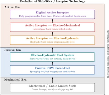
By the late 1980s and 1990s, the need for more sophisticated tactile feedback was evident, especially in advanced military programs that demanded high agility and carefree handling qualities. Figure 2 illustrates the staged evolution of inceptor technology. Hosman et al. [Reference Hosman, Benard and Fourquet12, Reference Hosman, Benard and Fourquet22] and Hegg et al. [Reference Hegg, Smith, Yount and Todd23] discussed the feasibilities and advantages of implementing the active inceptor into a modern aircraft cockpit controls and demonstrated the features of an experimental active sidestick controller. BAE Systems started developing their active inceptor technology for military application around the same period of time, intended for the Joint Strike Fighter Program, which was later equipped on the F-35 Lightning, representing a first in bringing an active force-feedback joystick into operational service [9].
Evolution of side-stick technology.

Another thread of early development occurred in flight simulation and research testbeds. Companies like Stirling Dynamics in the UK pioneered active control systems for flight simulators for more than 3 decades [24]. By the 2000s, Jeram integrated a Stirling Dynamics active sidestick into a UH-60 Black Hawk FBW test helicopter to evaluate in-flight tactile cueing [Reference Jeram25]. The research implemented soft stop and limit cue protection algorithms to warn and protect impending rotor blade stall, with the active inceptor providing a resistive force and vibration when limits are approaching. The success of such simulation trials showed that active inceptors could reliably operate in real flight conditions and meaningfully assist pilots in maintaining safe envelopes on helicopter applications [Reference Jeram25, Reference Whalley, Hindson and Thiers26].
Active control sticks have been extensively tested in rotorcraft and fighter aircraft simulation studies to address various handling and safety issues. In particular, active sticks have proven effective in mitigating Pilot-Induced Oscillations (PIO) and other handling quality issues [Reference Jeram and Prasad27, Reference Liu, Sun, Tan, Xu and Jiao28]. For the past decade, they have also been researched to other helicopter scenarios, including near-ground obstacle avoidance [Reference von Grünhagen, Müllhäuser, Abildgaard and Lantzsch29–Reference Binet and Rakotomamonjy31], and Vortex Ring State (VRS) protection [Reference Binet, Abildgaard, Taghizad and von Grünhagen32–Reference Dang-Vu34] etc. In fixed-wing aircraft, active control sticks have been utilized for flight envelope protection [Reference Van Baelen, Van Paassen, Ellerbroek, Abbink and Mulder11], mitigation of loss-of-control scenarios [Reference Klyde and McRuer35, Reference Klyde, Liang, Richards and Cogan36], flight path guidance and assistance [Reference Beeftink, Borst, Van Baelen, van Paassen and Mulder18, Reference Theunissen and Mulder37–Reference Latorre-Costa, Defay and Saussié39], and ground taxi assistance [Reference Galea, Zammit Mangion, Muscat, Thornton and Gauci40], more details will be discussed in Section 7. Additionally, active inceptor technologies have shown significant potential in collision avoidance during UAV tele-operation scenarios.
Overall, by the early 2000s, the technical viability of active inceptors was established, but they had yet to see widespread adoption beyond experimental use. Key challenges remain to achieve the necessary reliability and redundancy for safety-critical use, with an additional system and weight, as well as convincing pilots, regulators, and manufacturers of their benefits against its high development and integration price.
Nevertheless, active inceptors have gradually transitioned from experimental systems to certified, flight-critical components on both military and civil platforms. This evolution is summarised in Figure 3.
Timeline of major developments in active inceptor technology (1985–2025).

3.1. Evolution into operational service
The first aircraft to enter operational service with true active inceptor systems were primarily military. The Lockheed Martin F-35 Lightning is widely regarded as a landmark. It uses a BAE Systems active electronically back-driven sticks for all three of its variants. The active stick is engineered with full programmability to accommodate the fighter’s multiple control laws and flight regimes [Reference Harris41, Reference Krumenacker42]. The success of the F-35 Active Inceptor System demonstrated that active sticks could meet the stringent demands of a fighter aircraft environment and provided confidence for further applications [9]. BAE Systems also provides active inceptors to various military rotorcraft, for example, UH-60MU Black Hawk, CH-53K King Stallion and MH-47G Chinook. They can bring benefits to rotorcraft by cueing complex limits like mast torque, blade stall, or attitude constraints in degraded visual environments [9]. BAE Systems active inceptors are also supplied to the Embraer KC-390 military transport and the South Korean KAI T-50 Golden Eagle [9].
The implementation of active inceptor technology into civil aviation did not start until the first decade of the 21st century, due in part to the conservatism of airliner flight deck designs, the highly automated control systems, certification hurdles and the higher price of the active inceptor system. The breakthrough came in the business jet sector, Gulfstream’s G500 and G600 models, first certified in 2018, debuted the first civil certified active sidesticks, supplied by BAE Systems [Reference Taylor, Essenberg, Horne and Hugon43, Reference Taylor, Narisetti, Stewart and Hildebrand44]. In these aircraft, each pilot’s sidestick is an active inceptor unit, electronically linked to synchronise the movement and provide tactile feedback of both the autopilot and the other pilot inputs. The coupled active inceptors give both pilots immediate awareness of the other’s control actions, and also presents an intuitive cue of autopilot engagement, where the sticks physically move when the autopilot adjusts the controls. The Gulfstream design team [Reference Taylor, Essenberg, Horne and Hugon43] compared the effect of traditional control yoke and active control stick on pilot tracking performance in a flight simulator. Ten pilots, none of whom had experience on flying with a side stick, took part in the experiment. Test scenarios included climbing turn manoeuvres, such as, pitch, roll and airspeed errors, steep turn manoeuvres, upset recovery and landings. The results also considered pilot feedback. The conclusion shows that the active control stick performs as well or even better than the traditional control yoke. There is no significant difference for climbing turn and steep turns, however, the Active Control System assists pilots with an average 6 seconds faster recovering time for upset recovery, which includes moderate and wake turbulence on both left and right side. Given the conclusion that the active control stick does not provide any negative effect during pilot manual flight path control, at the same time it could assist pilot to perform better and faster on recovering the aircraft and provide a safer flight experience [Reference Taylor, Essenberg, Horne and Hugon43].
In Europe, future fighter and trainer concepts are considering active inceptors, and active sidestick products are offered by several suppliers, such as, BAE Systems, Liebherr Aerospace, Stirling Dynamics etc. Experimental aircraft and research simulators, such as DLR’s Flying Helicopter Simulator (FHS) have been fitted with active sidesticks to investigate advanced pilot assistance functions [Reference von Grünhagen, Müllhäuser, Abildgaard and Lantzsch29]. DLR has integrated active sidesticks from Liebherr and Stirling Dynamics into its EC135 test helicopter as early as 2007, enabling trials of haptic feedback for helicopter manoeuvring and envelope protection [Reference von Grünhagen, Müllhäuser, Abildgaard and Lantzsch29].
Today, research on active inceptor systems is increasingly seen in next-generation aircraft designs and urban air mobility (UAM), such as electric vertical take-off and landing (eVTOL) aircraft, which employ simplified and highly augmented controls where haptic feedback could compensate for low pilot training or high automation. Bromfield also suggests that introducing FBW into small general aviation or urban air mobility vehicles will likely necessitate active inceptors to avoid the shortcomings of passive controls [Reference Bromfield45].
4. AIS case studies
Figure 4 presents the current AIS research on both fixed-wing aircraft and rotorcraft.
Current AIS studies.

4.1. Flight envelope protection
Research by Van Baelen et al. [Reference Van Baelen, Ellerbroek, Van Paassen and Mulder46] highlights the use of haptic feedback to augment pilot awareness of flight envelope boundaries. The study proposed several forms of feedback: discrete force cues triggered when nearing the envelope limits, progressive increases in control stick stiffness as aircraft states approach critical boundaries, stick shaker activation at low velocities, and automated adjustments of the control stick neutral position in overspeed and critically low-velocity scenarios [Reference Van Baelen, Ellerbroek, Van Paassen and Mulder46].
In the longitudinal axis, the haptic feedback communicates velocity protection, angle-of-attack (AOA) protection, and load factor limitations. Force gradients and neutral stick positions dynamically adjust based on the proximity of the aircraft state to the defined safe flight envelope, significantly improving pilot awareness and decision-making in near-critical conditions [Reference Van Baelen, Van Paassen, Ellerbroek, Abbink and Mulder11, Reference Van Baelen, Ellerbroek, Van Paassen and Mulder46]. For instance, a discrete ‘tick-on-the-stick’ force cue alerts the pilot upon leaving the predefined safe flight envelope (SFE), accompanied by increasing stick stiffness if the pilot continues steering toward the flight envelope limits [Reference Van Baelen, Van Paassen, Ellerbroek, Abbink and Mulder11].
The result of these studies shows that discrete haptic feedback, i.e. force pulses or ticks, proved effective in alerting pilots when the aircraft exited the SFE. Secondly, progressive stiffness cues were beneficial in conveying the increasing criticality as aircraft states approached physical limits. However, results also indicated potential dependency on automated guidance from force feedback, as pilot performance notably degraded when such cues were removed [Reference Van Baelen, Van Paassen, Ellerbroek, Abbink and Mulder11, Reference Van Baelen, Ellerbroek, Van Paassen and Mulder46, Reference de Rooij, Van Baelen, Borst, van Paassen and Mulder47].
4.2. Loss of control (LOC) protection
Several innovative cueing methods have been developed and evaluated to mitigate aircraft loss of control incidents, including Smart-Cue, Smart-Gain, Safe-Cue, and Safe-Gain approaches [Reference Klyde, Liang, Richards and Cogan36, Reference Klyde, Liang, Alvarez, Richards, Adams and Cogan48, Reference Klyde, Lampton, Richards and Cogan49]. The Smart-Cue method introduces gradient force feedback, damping, and frictional forces which vary based on the aircraft position error and its rate-of-change of this error, activating only when errors surpass predefined thresholds. Studies demonstrate that the Smart-Cue effectively supports pilots during pitch axis manoeuvres but exhibits limited assistance in roll axis manoeuvres [Reference Klyde and McRuer35, Reference Klyde, Liang, Richards and Cogan36].
The Smart-Gain method employs adaptive command attenuation driven by dynamic distortion measurements, effectively reducing pilot inputs to prevent exacerbation of control surface actuator rate limitations. By modulating the pilot input based on real-time position errors, the Smart-Gain concept has shown significant potential in alleviating PIO scenarios, particularly those associated with nonlinear flight control system responses such as actuator saturation [Reference Klyde and McRuer35, Reference Klyde, Liang, Richards and Cogan36].
Safe-Cue system expands upon the Smart-Cue concept by utilizing system errors, differences between actual aircraft responses and nominal system models, rather than positional errors alone. Safe-Cue provides intuitive haptic feedback, and adaptive command gains specifically designed to support pilot interactions with adaptive controllers, particularly during aircraft damage or failures [Reference Klyde, Liang, Alvarez, Richards, Adams and Cogan48, Reference Klyde, Lampton, Richards and Cogan49]. The Safe-Cue approach effectively reduces pilot-vehicle oscillations, enhances system stability, and ensures pilots can maintain control even under significant system degradation [Reference Klyde, Lampton, Richards and Cogan49].
In conclusion, the Smart-Cue/Smart-Gain approaches are primarily aimed at mitigating actuator rate limiting and associated nonlinear behaviours, while the Safe-Cue method expands applicability to a broader range of nonlinearities and system failures. Results consistently show that the combination of these methods eliminate unfavourable pilot-vehicle coupling tendencies and restore predictable, linear aircraft responses. Consequently, pilots can successfully execute challenging manoeuvres despite failures or damages that might otherwise lead to LOC [Reference Klyde and McRuer35, Reference Klyde, Liang, Richards and Cogan36, Reference Klyde, Liang, Alvarez, Richards, Adams and Cogan48, Reference Klyde, Lampton, Richards and Cogan49].
Aircraft Pilot Coupling (APC) or Pilot-induced-oscillation (PIO) is a big contributor to aircraft LOC, which is an unintentional oscillation resulting from pilot overcontrol [Reference Mitchell and Klyde50]. Xu et al. [Reference Xu and Wu51] designed an AIS for PIO mitigation, based on pilot comprehensive evaluation, using a scalogram-based PIO metric [Reference Klyde, Schulze, de Mello, Mitchell, Cameron, Cunliffe and White52]. The research shows a single force gradient design with a stiffness of 800 N/m gives the best result in PIO mitigation [Reference Xu and Wu51].
4.3. Flight path and guidance assistance
The Tunnel-in-the-Sky (TIS) display, a three-dimensional visual tool that provides intuitive trajectory guidance, has significantly improved pilot performance during aircraft approaches by simplifying flight path tracking [Reference Theunissen and Mulder37, Reference Mulder38, Reference Crunwald, Robertson and Hatfield53]. However, reliance on visual displays such as TIS inherently increases head-down time, potentially reducing pilot situational awareness and multitasking capabilities [Reference Beeftink, Borst, Van Baelen, van Paassen and Mulder18]. Research suggests that integrating haptic feedback through active inceptor systems could mitigate these drawbacks by enhancing task-sharing performance and reducing cognitive load [Reference Beeftink, Borst, Van Baelen, van Paassen and Mulder18].
A study was conducted using a Cessna Citation I simulator to evaluate the effectiveness of combining visual (TIS display) and haptic feedback modalities [Reference Beeftink, Borst, Van Baelen, van Paassen and Mulder18]. The study assessed primary flight control performance, secondary task management (external visual monitoring), subjective mental effort, and gaze behaviour using eye-tracking technology, with 12 pilots of varying flight experience. The primary task involved accurately tracking a TIS-defined trajectory, while the secondary task required visual identification of distinct shapes displayed externally to assess head-up behaviour.
The research employed proportional force cues directly corresponding to predicted lateral and vertical positional errors indicated by the TIS display. The active inceptor provided continuous guidance forces based on these predicted errors, effectively transforming a complex flight path tracking task into a simplified two-dimensional pursuit tracking task, thus aligning closely with pilots’ intuitive proportional control strategy [Reference Beeftink, Borst, Van Baelen, van Paassen and Mulder18].
The experimental results demonstrated that integrating haptic feedback significantly improved both primary and secondary task performance, especially under high workload conditions such as smaller tunnel widths and curved trajectory segments. Specifically, pilots exhibited reduced tracking errors, increased accuracy in the external visual task, reduced mental workload ratings, and increased head-up time, suggesting enhanced situational awareness and improved multitasking capacity and enhanced overall flight performance and safety [Reference Beeftink, Borst, Van Baelen, van Paassen and Mulder18].
Latorre-Costa et al. [Reference Latorre-Costa, Defay and Saussié39] proposed a guidance assistance system within an A320 simulation environment using an active yoke to assist pilots in capturing and maintaining precise aircraft headings. The system measures the bearing between the aircraft and the subsequent waypoint, compares this to the actual aircraft heading, and calculates appropriate haptic feedback forces applied through the yoke. The results indicated no significant performance differences on the simpler path scenario, whereas on the more complex path, active feedback notably reduced variance in pilot control inputs. This finding suggests that active haptic feedback has the potential to enhance guidance control accuracy and simulation handling quality, particularly under challenging conditions [Reference Latorre-Costa, Defay and Saussié39].
4.4. Taxiing assistance
Galea et al. [Reference Galea, Zammit Mangion, Muscat, Thornton and Gauci40] proposed to employ an active side stick controller designed to simplify ground operations by integrating multiple control functionalities into a single intuitive interface, augmented with haptic feedback. The active side stick system provides pilots with tactile cues, proportional to the aircraft’s lateral deviation from the taxiway centreline, guiding the aircraft back toward the centreline, thereby enhancing directional control and reducing cross-track errors. PIL tests demonstrated the efficacy of this active side stick approach, indicating improved taxiing precision, especially beneficial under low visibility conditions. Pilot evaluations highlighted reduced workload and increased operational intuitiveness, thereby increase taxiing safety and efficiency. Though certain refinements such as sensitivity adjustments and improved haptic response profiles were suggested to enhance usability further.
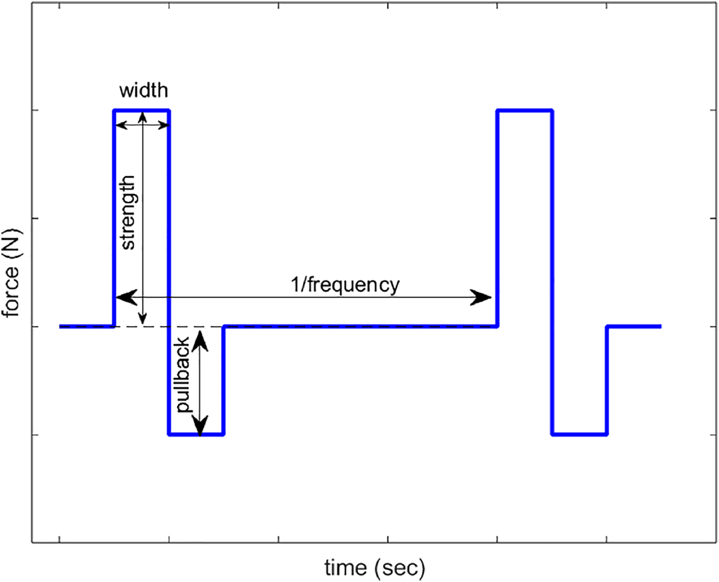
Ticker force command for rotorcraft near ground obstacle avoidance [Reference Walko and Müllhäuser54].

4.5. Near-ground rotorcraft obstacle avoidance
Near-ground, low-speed helicopter operations carry significant collision risks due to ground obstacles. Traditional visual and auditory warning systems can often be overlooked or ineffective under high stress. The use of AIS to mitigate collision risk has been explored [Reference Müllhäuser30, Reference Binet and Rakotomamonjy31].
AIS is used to translate obstacle proximity into force vectors that guide pilots away from potential collisions. For instance, Müllhäuser et al. [Reference Müllhäuser30] evaluated two force strategies: a continuously increasing force combined with a stiffening spring gradient, and a pulsing, frequency-modulated force to indicate proximity and urgency.
A notable implementation, haptic ticker, provides short, directional pulses to alert pilots of nearby obstacles, as shown in Figure 5 [Reference Walko and Müllhäuser54]. This system activates within a critical proximity, generating intuitive haptic cues that indicate both distance and direction away from the obstacle. Evaluations in DLR’s Air Vehicle Simulator demonstrated a significant reduction in collision rate from 84% without the system to less than 4% with the ticker, indicating substantial safety improvements. Pilot feedback underscored the system’s intuitiveness and its potential to prevent approximately 75% of obstacle-related accidents [Reference Walko and Müllhäuser54].
4.6. Rotorcraft vortex ring state protection
Vortex Ring State (VRS) is a hazardous aerodynamic condition that occurs when helicopters descend rapidly at low forward speeds, resulting in airflow recirculation, loss of lift, and reduced controllability, particularly critical at low altitudes [Reference Jimenez, Desopper, Taghizad and Binet55]. ONERA developed a semi-empirical induced velocity model to predict VRS boundaries and inform flight envelope protections [Reference Jimenez, Desopper, Taghizad and Binet55].
ONERA and DLR have implemented this model within an active sidestick system providing haptic feedback to enhance pilot awareness and prevent VRS. The system delivers force-feedback cues via collective and cyclic controls based on real-time helicopter flight data. Simulator tests conducted by DLR demonstrated that haptic cues with force gradient significantly reduced pilot workload and improved descent management, whereas cyclic stick tick cues increased workload and were less effective [Reference Binet, Abildgaard, Taghizad and von Grünhagen32, Reference Abildgaard and Binet56].
Empirical evaluations showed collective cueing reduced pilot inputs by up to 70%, maintained safer descent rates, and notably minimized occurrences of unsafe VRS conditions [Reference Binet, Abildgaard, Taghizad and von Grünhagen32, Reference Dang-Vu34, Reference Abildgaard and Binet56].
4.7. Dual pilot operation
Research into active inceptor systems explores the potential for electronically coupling sidesticks, aiming to enhance communication and situational awareness between pilot flying (PF) and pilot monitoring (PM) [Reference Hegg, Smith and Yount57].
In the context of dual pilot operations, a notable study revisited the Air France AF447 incident, where lack of sidestick coupling contributed to degraded crew situational awareness and subsequent loss of aircraft control [Reference Uehara and Niedermeier20, 58]. The research employed a simulation scenario replicating the accident conditions with four participants, comparing outcomes with and without sidestick coupling. Results demonstrated that active sidestick coupling substantially enhanced PM awareness by providing haptic feedback corresponding to PF inputs, suggesting potential improvements in pilot communication and reduced accident probability [Reference Hegg, Smith and Yount57].
Uehara et al. [Reference Uehara and Niedermeier17] also conducted experiments using an Airbus A320 fixed-base simulator to investigate active sidestick coupling during landing flare manoeuvres. Utilizing recorded PF inputs coupled to PM sidesticks, twelve pilots evaluated scenarios involving the decision-making process for potential control takeover. Findings confirmed the coupling function significantly improved PM situational awareness regarding PF control actions [Reference Uehara and Niedermeier17].
The EFAICTS (Ergonomic Impact and New Functions induced by Active Inceptor Integration in Cockpits) project, utilizing active inceptor technology from Safran Electronics & Defence, specifically targeted the human-centred cockpit design for civil tilt-rotor aircraft [Reference Binet and Perret59]. The project examined pilot coupling strategies using active inceptors across three operational modes: Master/Slave, Dual, and Decoupled modes. Comprehensive scenarios including glide slope guidance, failure warning cues, and corridor protection functions were developed and assessed, demonstrating notable improvements in crew situational awareness, reduced workload, and enhanced collaboration [Reference Binet and Perret59].
5. AIS architecture in flight control system
The AIS should not intend to override or replace pilot authority, but rather to inform pilots with certain limits, in support of mission objectives, improve situational awareness and reduce workload. Unlike fully autonomous systems, AIS maintains the pilot-in-the-loop by providing real-time haptic feedback that reflects the current state of flight control system, aircraft aerodynamics and control surfaces [Reference Hosman, Benard and Fourquet12]. It should be designed to augment, but not to substitute the existing flight control architecture by projecting critical information to pilots through tactile cues. Figure 6 illustrates a representative control block diagram showing the integration of AIS within an FBW flight control system, proposed by the author.
AIS architecture.

AIS should be able to adapt different control laws. In normal law operation, AIS should reinforce the flight control system (FCS) by providing haptic cues that reflect aircraft control surfaces and dynamics. However, when the system degrades to alternate or direct law, often due to loss of sensors, loss of envelope protection logics, or loss of control augmentation, in such case, continue to provide the same haptic cues as normal laws might be misleading or even dangerous. Force feedback derived from invalid or partial sensor data may incorrectly suggest flight protection. Therefore, AIS behaviour must adapt accordingly, prioritizing pilot authority over system. The AIS should allow the pilot to switch it to passive spring-damper mode in failure conditions where automation and sensors cannot be trusted. Research should be carefully conducted on how AIS should function in order to provide maximum help to the pilot and minimum damage during failure modes.
AIS should be able to provide flight phase-dependent feedback. Different flight phases have different control priorities. Although cruise phase takes the majority of time during flight, only 6% of accidents occur during cruise in the decade from 1990–1999 [Reference McLean1]. During cruise, stability is high so fewer inputs and less workload is required from the pilot. The author suggests that the AIS have a stiff breakout detent and lower sensitivity to avoid pilot mis-touch and overcorrection. During take-off, approach and flare landing phases, precise longitudinal control is crucial [Reference Gautrey60], the AIS should be designed to enhance direction, flight path tracking and AOA limitation, and so minimise the risk of APC/PIO. Handling quality assessment criteria discussed in Section VI could be considered during the AIS algorithm design. For ground operations, an error-based force displacement could be applied as discussed by Galea et al. [Reference Galea, Zammit Mangion, Muscat, Thornton and Gauci40].
6. Certification standards and regulatory considerations
Regulatory authorities and standards organisations have established criteria to ensure flight safety and system reliability. While specific regulations for Active Inceptor Systems (AIS) are currently limited, existing standards for conventional flight control systems provide a foundational framework that can guide the development and certification of AIS.
6.1. Control force and cueing criteria for fixed-wing aircraft (MIL-STD-1797A)
Military fixed-wing aircraft flying and handling qualities have long been specified by standards like MIL-F-8785C [61], mainly for pre-1980s fly by cable (FBC) aircraft, and its successor MIL-STD-1797 [62], which expanded to cover modern FBW aircraft, and gives more quantitative criteria using frequency domain criteria. These standards define desirable control characteristics such as stability, responsiveness, and control forces for various classes of aircraft and flight phases. Even though these were written with conventional controls input, e.g. sidestick and yoke, in mind, they could influence active inceptor design to ensure handling quality level, pilots’ control feel.
-
1. Control Force Gradient: MIL-STD-1797 guided that the stick force per g must be linear or progressively increasing with load factor, excessive force gradient may cause higher pilot workload or fatigue [62].
-
2. Breakout: MIL-STD-1797A recommends that breakout forces and control friction be low enough to not cause abrupt inputs, but not so low that the control feels sloppy. Typically, breakout forces on the order of 0.5 lb to 1 lb (about 2 N to 4.5 N) and friction under 1.12 lb (5 N) are desired for precise control [62].
-
3. Force Feedback in non-linear control laws: The standard acknowledges the challenges of force feedback in highly augmented aircraft, if an aircraft has a carefree manoeuvring limiter, the pilot might not feel the aerodynamic cues of an approach to stall. MIL-STD-1797 encourages supplemental cues in such cases. Active sticks fulfil this by injecting synthetic feel to indicate when limiters are active [62].
-
4. Trim changes: In a conventional aircraft, changes in configuration or airspeed induce stick forces. FBW aircraft often auto-trim these out. MIL-STD-1797 suggests that predictable cues for structural configuration changes are important for pilot awareness. An active inceptor can optionally add a detent or transient force when a major configuration change happens, for example, flap deployment, to mimic this cue [62].
Military rotorcrafts also have similar standards, ADS-33E, for handling qualities, which place importance on force feel characteristics in hover and agility tasks.
6.2. Certification specification for force-gradient and control integrity (EASA CS-25)
EASA CS-25 (Certification Specification 25) is the European Union Aviation Safety Agency’s set of airworthiness standards that define the certification requirements for large commercial aircrafts. As per CS 25.175 [63], an aircraft must demonstrate positive static longitudinal stability through a consistently positive stick force gradient across various flight configurations. The average gradient of the stick force–airspeed curve shall not be less than 1lbs (4 N) for every 11.2 km/h (6 kn) increase in speed, CS 25.173. The stick force vs. speed curve must exhibit a stable slope.
The regulation stipulates that even under the most adverse mis-trim conditions, the stick force vs. load factor (g) curve must remain positively sloped, ensuring that increasing aft stick force corresponds to increased g, and vice versa (CS 25.255 [63]). Any decrease in stick force gradient with changing load factor must be gradual and not so significant that it compromises the pilot’s ability to control pitch attitude and g-load effectively (AMC No. 2 to CS 25.143(g) [63]).
Stick shaker and stick pusher is suggested to be applied for stall warning according to AMC 25.207 [63].
In general, progressive and predictable force-displacement should be mapped across all phases of flight. These constraints are particularly critical for the design of active inceptors, where longitudinal force-displacement profiles are software-defined. To ensure pilots always receive correct and intuitive force cues in pitch, regardless of the aircraft’s configuration or speed, safe and intuitive handling, even in degraded or mis-trimmed conditions, the force feedback logic must be compliant with CS 25. The active inceptor must not only produce the required control authority but also maintain consistent pilot cueing through predictable and non-reversing force feedback [63].
6.3. US regulations on pilot-force cue integrity for transport aircraft (FAA 14 CFR 25)
FAA 14 CFR Part 25 is the section of the U.S. Federal Aviation Regulations that sets the airworthiness standards for large transport aircraft. The FAA Advisory Circulars generally align with EASA on force-gradient regulations on load factors and speed where, furthermore, Part 25 ${\rm{\S}}$
25.671 mandates that the flight control system must include provisions to clearly indicate which pilot has control and to alert the crew when the primary controls approach the limits of their operational authority [64]. These requirements can be effectively addressed through AIS using dual-stick synchronization, programmable force feedback, and detent mechanisms to provide intuitive haptic cues.
${\rm{\S}}$
25.671 mandates that the flight control system must include provisions to clearly indicate which pilot has control and to alert the crew when the primary controls approach the limits of their operational authority [64]. These requirements can be effectively addressed through AIS using dual-stick synchronization, programmable force feedback, and detent mechanisms to provide intuitive haptic cues.
Additionally, FAA Advisory Circulars, such as AC 25-7D [65], generally align with EASA guidance in stipulating appropriate force-gradient characteristics in response to variations in load factor and airspeed, reinforcing the need for consistent and predictable control force behaviour across all phases of flight.
6.4. Aerospace active inceptor systems for aircraft flight and engine controls (SAE ARP 5764)
ARP 5764 is a recommended practice providing comprehensive recommendations for active inceptor design, performance and safety assessment. It defines force, frequency, and time-domain design limitations for active inceptor to ensure they meet the required handling quality and pilot cueing standards. In longitudinal and lateral control axes, for structural load requirement, the maximum continuous force is typically limited to 133 N (30 lbf) for sidesticks and up to 267 N (60 lbf) for centre-sticks or collective inceptors, depending on axis configuration. Breakout forces must exceed 2.2 N (0.5 lbf), to avoid uninteded force input and vibration. [8]
In the frequency domain, ARP 5764 requires the AIS to achieve a minimum closed-loop bandwidth of 5 Hz, with gain and phase margins of at least 6 dB and 45°, respectively, to preserve system robustness and prevent pilot-induced oscillations. The active actuator system must exhibit a settling time below 150 ms for a step input, and rise time under 75 ms, with overshoot capped at 10% of the commanded force. These criteria ensure timely and accurate force cueing without lag or excessive amplification, both of which could deteriorate handling qualities under dynamic flight conditions.
ARP 5764 also advises that active inceptors should include failure fallback modes, where passive force-displacement characteristics, e.g. via springs-dampers, take over to maintain minimum control cueing during actuator or power loss. In all modes, force-displacement curves must remain monotonically increasing, preventing reversal or dead zones that could mislead the pilot. These specifications directly support compliance with CS 25.143 and CS 25.255, where stick force gradient and pitch axis cueing integrity are essential for maintaining positive static and dynamic longitudinal stability.
SAE ARP 6001, for passive sidesticks requirement [66], and other human factors guidelines provide baseline expectations which active sticks should also fulfil in their passive mode.
In summary, the regulatory framework for AIS in transport aircraft remains relatively underdeveloped, with no comprehensive design-specific standards, however, regulations and advisories for conventional control input could give a baseline in AIS research and development. Notably, the successful certification of AIS in Gulfstream cockpits [67] has established an important precedent, effectively paving the way for broader adoption. For future aircraft programs, particularly in the commercial transport sector, the availability of SAE ARP 5764 and historical certification examples provides a structured pathway. However, each new AIS design laws will continue to require careful validation through human factor assessments, and compliance with handling quality criteria.
7. Handling quality assessment
Aircraft handling quality refers to how effectively a pilot can control an aircraft and achieve desired performance throughout its operational envelop. In the context of AIS, handling quality extends beyond traditional aerodynamic and control system characteristics to include the pilot-in-the-loop human-machine interaction by force feedback cues. While Section 6 covered the regulatory requirements and advisories related to handling quality of sidesticks and active inceptors, this section focuses on how AIS designs could be evaluated, including experimental and theoretical handling quality criteria, in both subjective pilot rating and objective engineering criteria.
7.1. Subjective handling quality assessment
The standard subjective metric is the Cooper-Harper Handling Qualities Rating (CHR) scale. The CHR is a well-established subjective method of assessing pilot-in-the-loop handling qualities. Pilots rate aircraft based on workload, precision and control ability using a scale from 1(excellent) to 10 (unacceptable), as shown in Figure A1 in Appendix [Reference Cooper and Harper68]. Traditionally, extensive piloted simulations and flight tests are conducted where pilots perform defined manoeuvres and assign handling quality rating [Reference Lusardi, Blanken, Ott, Malpica and Von Gruenhagen15]. For AIS, the CHR would be particularly useful in capturing pilot feedback on how force cues influence perceived control harmony and workload. Lower CHR rating should be reached when AIS is tuned to match control feedback with the aircraft’s dynamic response.
The NASA Task Load Index (NASA-TLX) is another widely adopted subjective workload assessment tool developed by NASA to evaluate perceived cognitive and physical demand during task execution. It captures six dimensions of workload, mental demand, physical demand, temporal demand, performance, effort and frustration [Reference Hart and Staveland69], as shown in Figure A2 in Appendix. NASA-TLX can provide insight to how the AIS haptic cues affect the pilot’s overall workload and task manageability. It can help establish a more comprehensive evaluation of handling quality between system and pilot experience.
7.2. Objective handling quality assessment
Objective handling quality criteria provides quantitative frameworks for evaluating how effectively an aircraft responds to pilot input. These criteria could offer valuable insights on how well the AIS system integrate into the aircraft dynamics and controls. By applying objective criteria to pilot-in-the-loop experiments in both time and frequency domains, how different AIS configurations affect system performance and aircraft handling quality can be assessed, thereby providing a rigorous foundation for AIS handling quality evaluation and optimization in an engineering perspective.
-
1. Bandwidth/Phase Delay Criterion:
This criterion evaluates the closed-loop frequency response of the aircraft, emphasizing how quickly and accurately it responds to pilot input. It was developed to overcome the limitations of time-domain metrics by characterizing how well the aircraft responds to pilot control inputs across frequency. The closed-loop input defined by this criterion is the stick force, which is highly related to AIS design. The frequency needed for different tasks throughout the flight is different, hence the bandwidth/phase delay criterion is task-oriented [Reference Mitchell, Hoh, Aponso and Klyde70]. Defining ${\omega _{\rm{BWphase}}}$
as the frequency where phase
${\omega _{\rm{BWphase}}}$
as the frequency where phase $\phi $
is at −135°, and
$\phi $
is at −135°, and ${\omega _{\rm{BWgain}}}$
as the frequency where gain is at 6dB above gain margin, the lesser of
${\omega _{\rm{BWgain}}}$
as the frequency where gain is at 6dB above gain margin, the lesser of ${\omega _{{\rm{BWphase}}}}$
and
${\omega _{{\rm{BWphase}}}}$
and ${\omega _{{\rm{BWgain}}}}$
is the bandwidth as shown in Figure 7 [Reference Gautrey60, Reference Mitchell, Hoh, Aponso and Klyde70]. The phase delay
${\omega _{{\rm{BWgain}}}}$
is the bandwidth as shown in Figure 7 [Reference Gautrey60, Reference Mitchell, Hoh, Aponso and Klyde70]. The phase delay $\tau $
is defined as
$\tau $
is defined as
 \begin{align}\tau = \frac{{{\rm{\Delta }}{\phi _{2{\omega _{180}}}}}}{{57.3 \times 2{\omega _{180}}}}\end{align}
Definition of bandwidth and phase delay criteria [Reference Mitchell, Hoh, Aponso and Klyde70].

As the criterion is task oriented, different boundaries are applied for different task categories. For instant, Field et al. showed that for active control transport aircraft, during landing approach scenario, ${\omega _{{\rm{BW}}}}$
should be larger than 1.4 rad/s,
${\omega _{{\rm{BW}}}}$
should be larger than 1.4 rad/s, $\tau $
less than 0.1 s,
$\tau $
less than 0.1 s, ${\omega _{{\rm{BW}}\gamma }}$
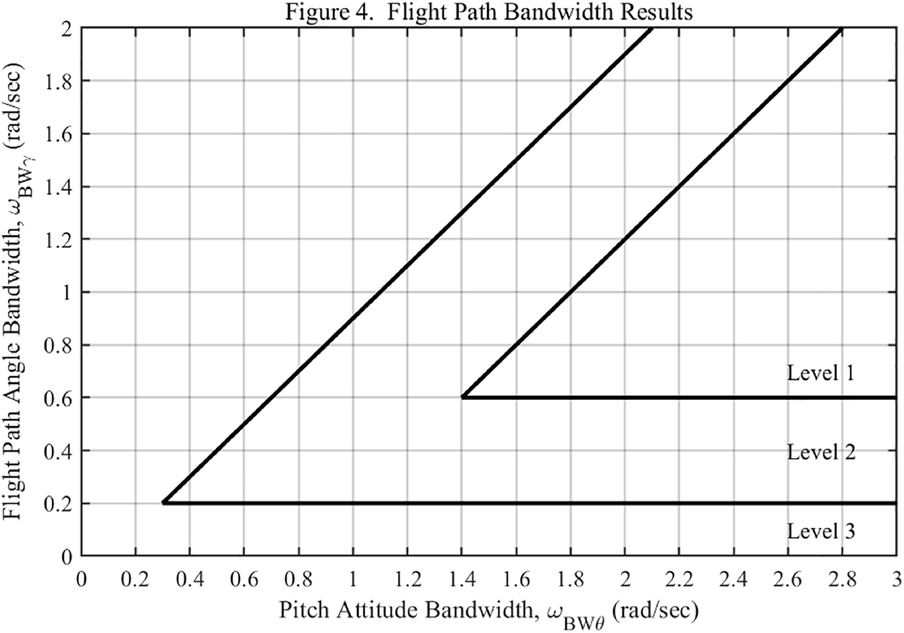
should be larger than 0.6 rad/s, as shown in Figures 8 and 9 [Reference Field, Rossitto and Mitchell71] to achieve level 1 handling quality. Since the Bandwidth/Phase Delay (BW/PD) criterion is inherently task-oriented, distinct boundary values are specified for different operational scenarios.
${\omega _{{\rm{BW}}\gamma }}$
should be larger than 0.6 rad/s, as shown in Figures 8 and 9 [Reference Field, Rossitto and Mitchell71] to achieve level 1 handling quality. Since the Bandwidth/Phase Delay (BW/PD) criterion is inherently task-oriented, distinct boundary values are specified for different operational scenarios.
-
2. Phase-Aggression Criterion (PAC):
Pitch attitude bandwidth [Reference Field, Rossitto and Mitchell71].

Flight path bandwidth [Reference Field, Rossitto and Mitchell71].

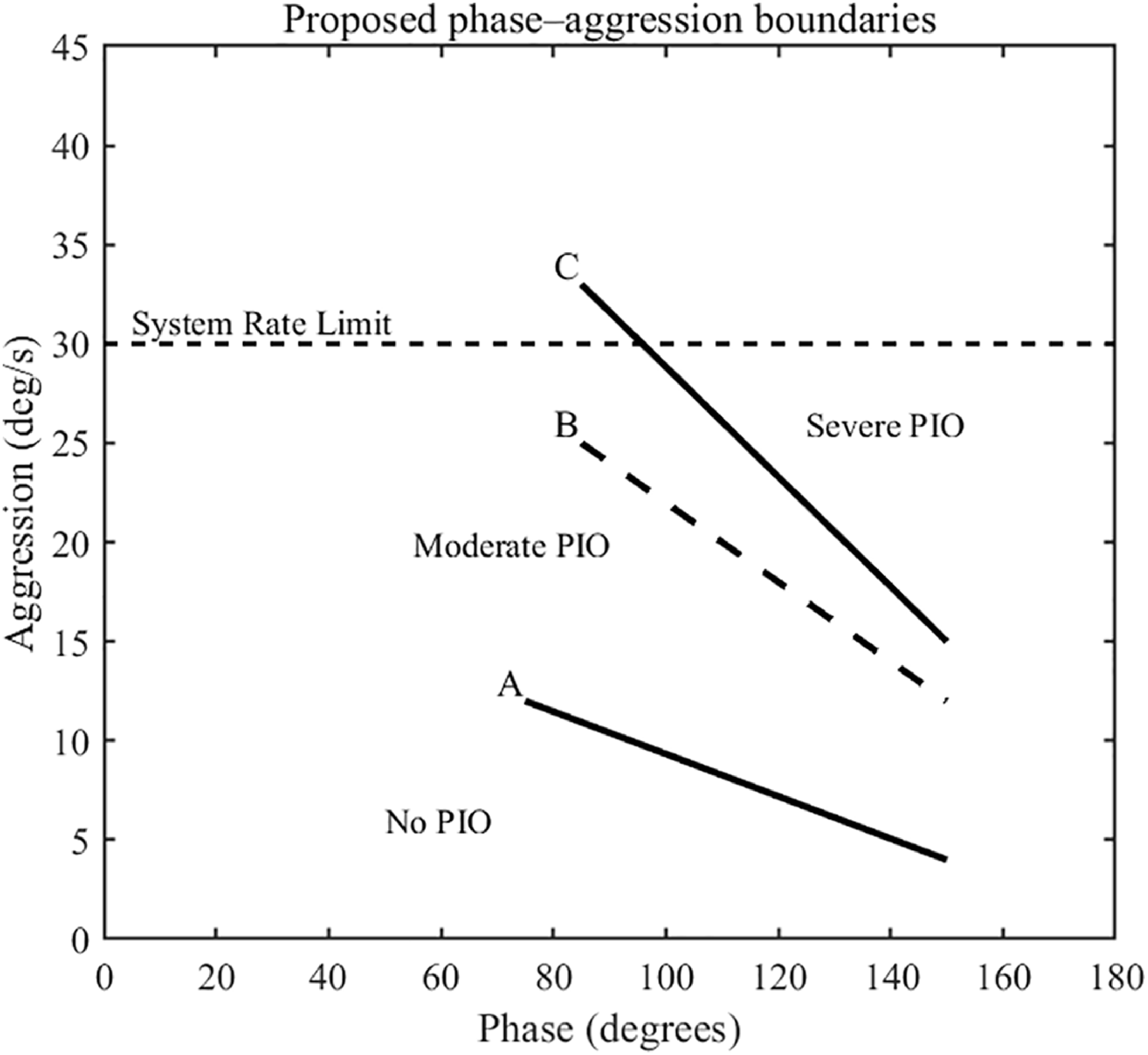
While not a primary handling-qualities criterion, the Phase Aggression Criterion (PAC) is well-suited as a quantitative APC/PIO detection metric. Deployed as a real-time monitor alongside Bandwidth/Phase-Delay (BW/PD) metrics and pilot subjective ratings, PAC gauges susceptibility to aircraft–pilot coupling by analyzing closed-loop pilot–inceptor–aircraft signals; it is particularly informative when linear pilot–vehicle dynamics dominate the oscillatory behavior. The aggression ${A_G}$
is calculated as the root mean square average of the control rate over defined time intervals,
${A_G}$
is calculated as the root mean square average of the control rate over defined time intervals,
 \begin{align}{A_G} = {H_s} \cdot {1 \over {\left( {{t_2} - {t_1}} \right)}}\mathop \smallint \nolimits_{{t_1}}^{{t_2}} \left| {\dot \delta \left( t \right)} \right|dt\end{align}
where the factor ${H_s}$
represents control sensitivity, defined as the ratio of control surface response to inceptor deflection controlled by the pilot,
${H_s}$
represents control sensitivity, defined as the ratio of control surface response to inceptor deflection controlled by the pilot, $\dot \delta \left( t \right)$
denotes the rate at which the pilot moves the inceptor, while
$\dot \delta \left( t \right)$
denotes the rate at which the pilot moves the inceptor, while ${t_2} - {t_1}$
is the sampling time. The aggression reflects the intensity of the pilot control input, in terms of both inceptor displacement and rate of movement. The phase
${t_2} - {t_1}$
is the sampling time. The aggression reflects the intensity of the pilot control input, in terms of both inceptor displacement and rate of movement. The phase $\phi $
, given by
$\phi $
, given by
 \begin{align}\phi = 360 \cdot \frac{{{T_{{\rm{q}},{\rm{peak}}2}} - {T_{\delta ,{\rm{peak}}2}}}}{{{T_{\delta ,{\rm{peak}}2}} - {T_{\delta ,{\rm{peak}}1}}}}\end{align}
indicates the lag between the pilot control input and the resulting aircraft pitch rate response. Jones et al. [Reference Jones, Jump and Lu72] provide Figure 10, illustrating the PAC boundaries for PIO detection.
Phase aggression boundary [Reference Jones, Jump and Lu72].

It should be noted that the PAC was initially developed on rotorcraft APC/PIO detections, its implementation on fixed-wing aircraft remains an open topic.
-
3. Performance Matrix Evaluation:
To quantify pilot performance with an active inceptor during a defined tracking phase, the root-mean-square (RMS) tracking error could be used to capture how precisely the pilot–AIS–aircraft loop follows the task, where the error is computed between the commanded reference and the pilot response. Stick-force measurements could also quantify the workload the pilot needed to achieve certain accuracy, which is especially relevant with AIS because haptic cues and active force shaping directly influence pilot input characteristics.
AIS enables the adjustment of haptic characteristics, allowing researchers to evaluate how different haptic profiles influence pilot control behaviour, tracking precision, and workload. For instance, adaptive force feedback may assist in reducing overshoot, improving tracking accuracy and reduce error, by shaping pilot input in real time, and hence, pilot-centred assessment remains indispensable. Objective metrics, e.g. BW/PD, PAC, RMS tracking error, should be interpreted alongside CHR and NASA-TLX to anchor handling-qualities levels of AIS. With the development of augmented aircraft handling-quality assessment, additional criteria may become valuable for objective AIS-in-the-loop evaluations, their boundaries and methods of application should be carefully researched.
It should be noted that human pilots cannot be treated as static controllers in the aircraft-pilot loop [Reference Bachelder and Aponso73]. A pilot’s control strategy adapts according to the aircraft dynamics, task requirements, command type, control environment, characteristics and position [Reference Jones, Klyde, Musso, Fegely, Gillett and Baik74] of the control inceptor. Studies on pilot neuromuscular (NM) systems show that pilots adjust their muscle stiffness and control impedance depending on factors such as inceptor sensitivity, feel system inertia, stick force gradient and inceptor placement, etc. For example, increasing stick force gradient requires larger muscle tension, which increases damping and reduces effective stiffness, thereby decreasing limb responsiveness and lowering closed-loop NM frequency [Reference Bachelder and Aponso73].
8. Future development and research directions
While the flight control systems (FCS) and pilot input interfaces in current-generation aircraft are highly mature and governed by well-established regulatory frameworks, the integration of AIS is likely to gain greater benefits in future aircraft architectures where conventional design may no longer be sufficient. Advanced aircraft designs such as Blended Wing Body (BWB) configurations, Urban Air Mobility (UAM) vehicles including eVTOLs, and next-generation fighter jets present unique handling challenges due to their unconventional structure and dynamics, high levels of automation, and aggressive flight envelopes. These vehicles demand more sophisticated aircraft-pilot interfaces to manage control precision, workload, and safety under dynamic conditions. AIS could offer a promising solution through programmable haptic feedback and adaptive cueing strategies that can enhance pilot situational awareness, mitigate adverse APC and improve handling quality. As such, it is expected to play a central role in shaping the aircraft-pilot interface of future flight control systems.
A promising direction for future research in AIS lies in the development of adaptive control algorithms tailored to specific aircraft configurations, flight conditions, and mission phases. Unlike traditional passive input devices, AIS offers the flexibility to modulate force-feedback characteristics dynamically, enabling optimization for unique control challenges across diverse platforms, particularly non-traditional airframes, as mentioned in the previous paragraph. These configurations often exhibit varying stability margins and control sensitivities across flight phases, requiring inceptor logic that adapts in real time. In parallel, the integration of pilot intent estimation and machine learning-based adaptation into AIS architectures could be another promising research avenue. By predicting pilot goals or identifying patterns in control behaviour, AIS could proactively adjust feedback cues to enhance precision, reduce workload, and mitigate the onset of adverse aircraft–pilot coupling. Together, these advances position AIS not only as a control input device but also as an adaptive interface in next-generation flight control systems.
Another area of future research is the design of AIS algorithms capable of adapting to aircraft failure conditions, such as sensor faults, control law degradation, or envelope protection loss. In such scenarios, continuing to provide nominal haptic cues may mislead the pilot, especially under high-stress or high-workload conditions. AIS should reflect the degraded status of the flight control system or aircraft response through simplified cueing. This requires future research and development on failure-mode force feedback logic that enhances situational awareness while minimising reliance on potentially faulty systems.
AIS provide a unique interaction between pilot and aircraft, which might need a unique pilot training process. Research is needed to evaluate how AIS would influence learning curves, response time, and trust development, potentially enabling more effective and safer training pipelines, especially for next-generation aircraft platforms.
From a certification and safety standpoint, future work should focus on establishing guidelines and regulatory pathways for AIS in civil and military aviation. This includes defining fault tolerance, redundancy, and failure modes specific to force-feedback control interfaces. Harmonization of standards between regulations such as EASA and FAA will be important.
Finally, the advancement of AIS represents a multidisciplinary challenge, requiring close integration of control systems engineering, aerodynamics, aircraft system design, and human factors. As AIS is fundamentally a cockpit technology, its ultimate value lies in how effectively it supports the pilot, it not only includes control law design and hardware performance but also on how intuitively and safely it communicates aircraft state and limits to the human pilots. Intensive pilot-in-the-loop evaluations are therefore essential, not only to assess technical performance but also to capture pilot perspectives and acceptance. Importantly, the introduction of AIS may reshape established practices, for example, pilot training requirements, handling expectations, and even the overall aircraft concept of operations (CONOPS) could evolve significantly compared to conventional inceptor architectures. Future research must bridge these domains, to develop an inceptor that is not only robust from the engineering point of view, but also cognitively aligned with pilot expectations and limitations. Collaborations between engineering, human factors, pilots, and regulatory bodies will be essential to establish new standards and best practices of AIS. A holistic approach will be critical in ensuring that AIS will evolve as an adaptive pilot-centred control interface for the next generation aircraft.
Competing interests
The authors declare none.
APPENDIX
Cooper-harper handling quality rating [Reference Cooper and Harper68].

NASA task load index survey [Reference Hart and Staveland69].








 Open access

