


1. SKA phase synchronisation
The Square Kilometre Array (SKA) (Dewdney et al. Reference Dewdney, Hall, Schilizzi and Lazio2009; Carilli & Rawlings Reference Carilli and Rawlings2004) is an international project to construct the world-leading radio telescope operating at frequencies between 50 MHz and 15.4 GHz. The first phase of the project (SKA1) will result in the construction of the initial 10% of the telescope’s receiving capacity. In this phase, a low-frequency aperture array comprising over a hundred thousand individual dipole antenna elements will be constructed in Western Australia (SKA1-LOW), while a mid-frequency array of 197 parabolic-dish antennas, incorporating the 64 dishes of the MeerKAT telescope (Jonas Reference Jonas2009), will be built in South Africa (SKA1-MID).
The SKA, being an interferometric array of individual antennas, requires coherent frequency reference signals at each antenna in the array to achieve phase coherence as required for performing interferometry and beamforming. In the case of the SKA1-MID, these reference signals will be generated centrally and transmitted to the antennas via fibre-optic links up to 175 km in length, with the longest links comprising mostly overhead cables (Grainge et al. Reference Grainge2017). Environmental perturbations add phase noise to the reference signals, degrading the array coherence, and thereby reducing the fidelity and dynamic range of the astronomical data (Cliche & Shillue Reference Cliche and Shillue2006).
Low-frequency arrays, such as the Murchison Widefield Array (MWA) (Lonsdale et al. Reference Lonsdale2009; Tingay et al. Reference Tingay2013) and the Low-Frequency Array (LOFAR) (van Haarlem et al. Reference van Haarlem2013), or intermediate frequency arrays with a compact configuration, such as MeerKAT (Jonas Reference Jonas2009; Julie & Abbott Reference Julie and Abbott2017) and the Westerbork Synthesis Radio Telescope (Hogbom & Brouw Reference Hogbom and Brouw1974), can attain sufficient phase coherence with a carefully designed passive frequency distribution system. In such systems, the frequency reference is simply transmitted to each antenna with no active attempt to control the fluctuations in phase. Arrays operating at higher frequencies and/or that are more extended in size, such as the Very Large Array (VLA) (Thompson et al. Reference Thompson, Clark, Wade and Napier1980) and the Australia Telescope Compact Array (ATNF 2016; Hancock et al. Reference Hancock2011), often incorporate a round-trip phase measurement system. Here the system records changes in phase and feeds forward a prediction of the future phase to the array’s correlator. However, for both the mentioned arrays, the system is currently not in use.
Telescopes operating at high frequencies, such as the Atacama Large Millimetre Array (ALMA) (Wootten & Thompson Reference Wootten and Thompson2009; Shillue, AlBanna, D’Addario Reference Shillue, AlBanna and D’Addario2004), or arrays that have a very large physical extent, such as the enhanced Multi-Element Radio Linked Interferometer Network (e-MERLIN) ((McCool et al. Reference McCool, Bentley, Garrington, Spencer, Davis and Anderson2008; Garrington et al. Reference Garrington2004), require actively stabilised frequency transfer to suppress the fibre-optic link noise to maintain phase coherence across the array. A similar scheme was also implemented using coaxial cable transmission lines for the compact, but high-frequency, Plateau de Bure Interferometer (Guilloteau et al. Reference Guilloteau1992). In addition, actively stabilised frequency transfer has also been proposed for synchronising what are currently individually referenced Very Long Baseline Interferometry (VLBI) antennas (He et al. Reference He2018; Clivati et al. Reference Clivati2017; Krehlik et al. Reference Krehlik2017; Dierikx et al. Reference Dierikx2016).
Given the combination of long fibre links, particularly from the increased environmental exposure of overhead cables, and relatively high frequencies of the astronomical observations, the SKA1-MID will therefore employ actively stabilised frequency transfer technologies to suppress the fibre-optic link noise to maintain phase coherence across the array (Grainge et al. Reference Grainge2017). Given these unique challenges and many specific technical requirement of the SKA, a novel, bespoke phase synchronisation system had to be designed specifically for the SKA.
In this paper we describe the technical details and practical implementation of the SKA1-MID phase synchronisation system. Following a 4-year development period, this system was formally selected for use on the SKA1-MID telescope in November 2017, and it has passed its Critical Design Review in November 2018. The system has been extensively tested using well-established metrology techniques while operating over installed fibre links (Schediwy et al. Reference Schediwy, Gozzard, Stobie, Malan and Grainge2017) and during field trials on long-haul overhead optical fibre, and further verified using novel astronomical techniques with existing radio telescope arrays (Gozzard et al. Reference Gozzard, Schediwy, Wallace, Gamatham and Grainge2017c).
2. Stabilised frequency transfer
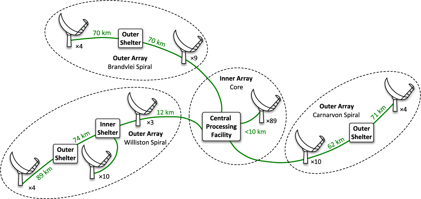
The SKA1-MID phase synchronisation system is based on the transmission of actively stabilised microwave (MW)-frequency reference signals that are generated at the SKA’s central processing facility (CPF), and then transmitted via separate fibre-optic links to each antenna. The star-shaped network topology of this phase synchronisation system matches the fibre topology of the SKA’s data network shown in Figure 1. This means that the same fibre-optic network that carries the astronomical data from the antennas to the CPF can also be used by the phase synchronisation system. The actively stabilised frequency transfer technique at the core of SKA1-MID phase synchronisation system builds on the technology used in ALMA’s distributed ‘photonic local oscillator system’ (Shillue et al. Reference Shillue, AlBanna and D’Addario2004), by incorporating advances made by the international frequency metrology community over the last decade (Foreman et al. Reference Foreman, Holman, Hudson, Jones and Ye2007; Lopez et al. Reference Lopez, Amy-Klein, Lours, Chardonnet and Santarelli2010b; Predehl et al. Reference Predehl2012), as well as several key innovations developed by the authors specifically for the SKA telescope (Schediwy et al. Reference Schediwy, Gozzard, Stobie, Malan and Grainge2017; Gozzard et al. Reference Gozzard, Schediwy and Grainge2018b; Schediwy Reference Schediwy2012; Gozzard, Schediwy, & Grainge Reference Gozzard, Schediwy and Grainge2018a).
Layout of the planned SKA1-MID telescope showing the locations of the antennas in the core and in the three spiral arms.
The SKA1-MID phase synchronisation system transmits a MW-frequency reference as a sinusoidal beat between two optical-frequency signals. As shown in Figure 2, the system is fully fiberised and generates this MW-frequency reference signal by physically splitting the optical signal from one laser into two arms of a fiberised Mach–Zehnder interferometer (MZI). In one arm of this interferometer, an MW-frequency shift is applied to the optical signal using a dual-parallel Mach–Zehnder modulator (DPM) whose input signals are biased in a manner to generate single-sideband suppressed-carrier (SSB-SC) modulation. This effectively produces an MW frequency shift of the optical signal. The other arm contains an acousto-optic modulator (AOM), which produces a radio-frequency shift on the optical signal.
Simplified schematic diagram of the stabilised frequency transfer technique forming the core of the SKA1-MID phase synchronisation system. DPM, dual-parallel Mach–Zehnder modulator; AOM, acousto-optic modulator; PD, photodetector; MW, microwave-frequency source; RF, radio-frequency source.
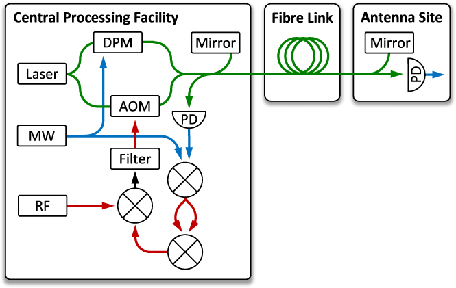
When the two MZI arms are recombined, the result is an MW-frequency beat between the two optical frequencies. This MW-frequency beat signal is transmitted over the fibre-optic link to each of the antennas, where it is converted into the electronic domain by a photodetector (PD). This electronic signal is then used as the frequency reference for the SKA1-MID receivers.
Active stabilisation of the transmitted signal is achieved through the use of an imbalanced Michelson interferometer (MI). At the antenna, a mirror reflects part of the optical signal back to the CPF forming the long arm of the MI. This reflected signal is then mixed with a copy of the transmitted optical signal originating from a short MI reference arm, and the resultant frequency modulation is extracted at the MI output using a PD. The electronic signal is then mixed with an MW-frequency reference to produce two radio-frequency signals. These are mixed together, and their product is further mixed with a radio-frequency reference to produce an error signal that contains an imprint of the fluctuations of the fibre-optic link. Appropriately filtering this signal and using it to steer the input frequency of the AOM closes the servo loop and effectively supresses the phase noise acquired on the fibre link as well as the MZI. The full technical details of the stabilisation technique are given in Schediwy et al. (2017); the remainder of this paper describes how this technique is used to build a phase synchronisation system designed specifically to meet the scientific needs and technical challenges of the SKA telescope.
3. SKA1-mid requirements
The SKA1-MID phase synchronisation system must meet a set of performance and operational requirements to ensure sufficiently high coherence between all the receptors to allow beam forming and interferometry. The principal requirements of the SKA1-MID phase synchronisation system dictate that the distributed reference signals be stable enough, over all relevant timescales, to ensure a sufficiently high coherence of astronomical data detected by the telescope array.
There are three specific phase stability performance requirements (Turner Reference Turner2015): The requirement for <1.9% coherence loss within a maximum integration period of 1 s is dictated by the correlator integration time; while <1.9% coherence loss over a 60-s integration period is determined by the period between in-beam calibrations. Finally, the requirement for <1 radian of phase drift over intervals up to 10 min is to ensure no wrap-around ambiguity in the phase solution between phase calibration observations. For the SKA1-MID phase synchronisation system, the dominant factor affecting the coherence loss is the choice of frequency of the transmitted reference signals. Therefore, the system is designed to transmit the highest MW frequency practicable given the constraints of its constituent key hardware elements.
The system must deliver the stabilised frequency reference signals to all 197 antenna sites across a range of expected operating conditions. The system must meet the above coherence loss requirements while subjected to temperatures between −5°C and +50°C within the dish pedestals and fibre link, and between +18°C and +26°C at the CPF and repeater shelters. In addition, the system must be able to operate with temperature gradients of ±3°C every 10 min within the dish pedestals and on the fibre link; and in non-condensing relative humidity between 40% and 60% within the dish pedestals and repeater shelters. The system must also be able to operate over the maximum link distances of 175 km on overhead fibre, with wind speeds up to 40 km per hour. Finally, the system must be resilient to seismic shocks of 1 m/s2.
Additional important requirements include the need for every individual antenna’s reference signal to be transmitted with unique frequency offsets that are integer multiples of exactly 10 kHz, to help the correlator to reject radio-frequency interference and for the system to rigorously limit any self-generated radio-frequency transmission (this is especially critical for the equipment at the antenna site, as it will likely be located at the antenna indexer). There are also limits on power consumption and on available space. Space is severely constrained in both the CPF and at the antenna indexer. Operational requirements include aspects of system availability, operability, maintainability, and monitoring. Finally, the SKA1-MID phase synchronisation system must meet all these requirements for less than 1/10th of the cost per link compared to the equivalent ALMA system.
4. Practical implementation
The SKA1-MID phase synchronisation system is an element within the SKA Signal and Data Transport (SADT) consortium’s Synchronisation and Timing (SAT) network. The full SADT element name of the SKA1-MID phase synchronisation system is SADT.SAT.STFR.FRQ, where STFR is an acronym of ‘Station Time and Frequency Reference’ and FRQ is an abbreviation of ‘Frequency’. The other elements within the SAT network are SAT.CLOCK, the SKA’s hydrogen maser clock ensemble and timescale; SAT.UTC, the system for disseminating absolute time, which utilises ‘White Rabbit’ (WR) technology (Dierikx et al. Reference Dierikx2016; Boven Reference Boven2017); and SAT.LMC, the local monitor and control system for the SAT network. The output of SADT.SAT.STFR.FRQ is passed to the SKA1-MID receivers, which are the remit of the DISH consortium. A simplified schematic of the SADT.SAT network architecture, showing the interrelationships between the various SADT.SAT network elements and DISH, is given in Figure 3.
Schematic diagram of the SKA1-MID Synchronisation and Timing (SAT) network. Signal colour code: pink, data; red, radio frequencies; blue, MW frequencies; green, optical frequencies/optical fibre; yellow, timing signals.
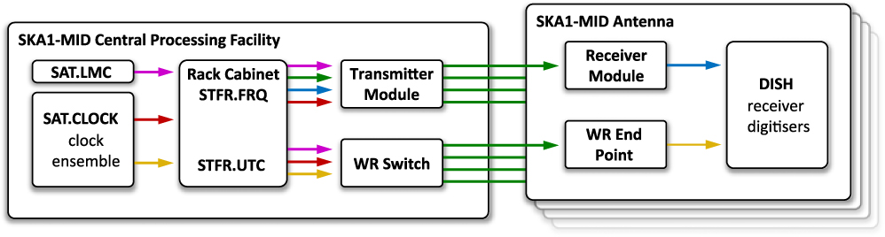
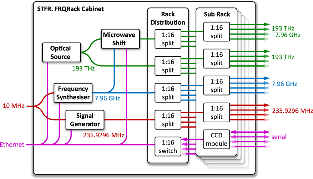
The SKA1-MID phase synchronisation system comprises a combination of 10 hot-swappable modules. The individual modules for transmitting and receiving the frequency reference signals (the Transmitter Module and Receiver Module , respectively), as well as the required mounting and racking hardware ( Rack Cabinet ) are shown in Figure 3. As shown in Figure 4, the Rack Cabinet incorporates the transmission laser ( Optical Source ), the MW-frequency source ( Frequency Synthesiser ), the module for encoding the MW-frequency signal into the optical domain ( Microwave Shift ), the reference radio-frequency source ( Signal Generator ), and some passive signal distribution modules ( Rack Distribution ). In addition, the Rack Cabinet holds multiple Sub Rack modules, each of which holds 16 Transmitter Modules . The simplified schematics for the Transmitter Module and Receiver Module are shown in Figure 5.
Schematic diagram of the SKA1-MID STFR.FRQ Rack Cabinet .
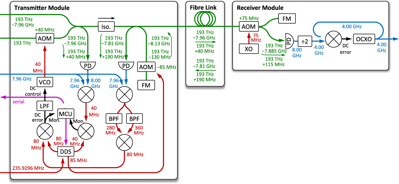
Schematic diagram of the SKA1-MID Transmitter Module and Receiver Module . AOM, acousto-optic modulator; PD, photodetector; Iso., optical isolator; FM, Faraday mirror; VCO, voltage-controlled oscillator; LPF, low-pass filter; MCU, microcontroller unit; BPF, band-pass filter; DDS, direct digital synthesiser; XO, crystal oscillator; ÷2, frequency divider; OCXO, oven-controlled crystal oscillator.
The Rack Cabinet takes input from SAT.CLOCKS and SAT.LMC, and produces a series of outputs that are passed to the Transmitter Module . The Transmitter Module transmits the reference signal across the fibre link to the Receiver Module . The Transmitter Module contains the servo-loop electronics and all monitor and control hardware. The Receiver Module includes a clean-up oscillator in a phase-locked loop (PLL), with the output then passed onto the SKA1-MID antenna receivers. Note, for the longest 14 of the total 197 SKA1-MID fibre links, optical amplification is required to boost the frequency reference signal strength; the Optical Amplifiers (not shown in the figures) are therefore located in various repeater shelters and antennas pedestals [see Schediwy & Gozzard (Reference Schediwy and Gozzard2018) for details].
Four of these modules are available commercially off-the-shelf (COTS), and the remaining six modules are bespoke assemblies made up of mainly COTS components. During the SKA Pre-Construction stage, the SKA project intends to keep the telescope designs ‘vendor agnostic’, and therefore no specific products are mentioned in the following section. Suitable components can be sourced from a range of vendors.
5. Implementation details
The specific implementation of the SKA1-MID phase synchronisation system is as follows: As per Figure 4, an optical signal with a frequency of 193 THz, generated by the Optical Source , is fed into a fiberised MZI. An MW-frequency reference signal of 7.96 GHz generated by the Frequency Synthesiser is applied to the DPM incorporated within the Microwave Shift module, which is tuned to produce a static MW-frequency shift of the optical signal, producing a new optical signal with a frequency of 193 THz–7.96 GHz. As shown in Figure 4, these two optical-frequency signals are split 256 ways to provide the required inputs for all of the system’s 197 active Transmitter Modules (the system also maintains several ‘hot’ spares).
In each Transmitter Module , the ‘servo’ acousto-optic modulator (AOM) adds +40 MHz to the 193 THz optical signal. This signal is then recombined with the DPM-shifted optical signal at the output of the MZI, and the signals pass an optical isolator (Iso.) to prevent any reflections from returning to the laser. The signals then enter an unbalanced MI, where the fibre link is the long interferometer arm, and the short interferometer arm acts as the physical reference for the optical phase. The MI reference arm contains a local ‘anti-reflection’ AOM, which is used to apply a static frequency offset of −85 MHz that allows the servo electronics to reject unwanted reflections from the link. Therefore, the optical reference signals at the PD have frequencies of 193 THz–8.13 GHz and 193 THz–130 MHz.
Two optical signals are transmitted across the fibre link; these have frequencies of 193 THz–7.96 GHz and 193 THz+40 MHz. As the signals are transmitted over the fibre link, they pick up phase noise resulting from optical path length changes occuring in the link due to environmental fluctuations. At the Receiver Module , a remote ‘anti-reflection’ AOM applies a static frequency of +75 MHz, produced by a simple crystal oscillator (XO), to the two optical signals. The signals are then split, with one set of signals being received at a PD, where the beat note results in an 8.00 GHz remote electronic signal. The second set of optical signals reflects off a Faraday mirror (FM) back across the fibre link to the Transmitter Module . Each optical signal receives an additional shift of +75 MHz when passing through the remote AOM a second time. The optical signals returning to the Transmitter Module now have frequencies of 193 THz−7.81 GHz and 193 THz+1pt190 MHz.
When the two reference frequency signals are mixed with the two reflected optical frequency signals, this results in six primary electronic mixing products. Of those six, the two MW-frequency mixing products with frequencies of 8.32 GHz and 7.68 GHz, contain the combination of phase noise information required by the system. The six mixing products are then mixed with the MW-frequency reference signal at 7.96 GHz. The two signals carrying the phase noise information produce radio-frequency signals at 360 and 280 MHz. An electronic MZI is used to separate the signals into two physical paths, with each path containing a band-pass filter (BPF) that is centred on one of the above frequencies. These filters reject the unwanted mixing products and any frequency inter-modulations. The two radio-frequency signals are then mixed and filtered to produce a signal with a frequency of 80 MHz. Finally, the 80 MHz signal is mixed with the local oscillator (LO) signal at 80 MHz to produce the DC servo error signal. The LO signal is generated by a direct digital synthesiser (DDS) with a clock of 235.9296 MHz. This clock frequency is produced by the Signal Generator , which is referenced by a 10-MHz signal from the SKA’s SAT.CLOCK hydrogen-maser clock ensemble.
The DC error signal is low-pass filtered to reject higher-frequency mixing products and then fed into a voltage-controlled oscillator (VCO). The VCO has a nominal centre frequency of 40 MHz. The VCO signal is used to drive the servo AOM, with variations in the DC error signal mapping directly to changes in AOM frequency. The servo loop attempts to drive the error signal to zero volts. As demonstrated in Schediwy et al. (Reference Schediwy, Gozzard, Stobie, Malan and Grainge2017), this has the effect of suppressing any phase noise added by the fibre link, as well as the MZI, that is stationary at timescales slower than the light round trip time. The DC error signal is also recorded using a microcontroller unit (MCU), and then relayed to SAT.LMC.
At the Receiver Module , the 8.00 GHz signal is divided by two (÷2) to produce 4.00 GHz. This signal is mixed with a signal of the same frequency produced by an oven-controlled crystal oscillator (OCXO). The resultant low-pass-filtered DC signal is fed into the control port of the OCXO. This creates a PLL where the 4.00 GHz output signal tracks the transmitted reference signal at frequencies below the PLL cut-off frequency, while the short timescale phase noise is dominated by the intrinsic stability of the OCXO. The optimal combined phase noise is expected when the PLL cut-off frequency is set below the frequency-equivalent light round trip time of the fibre link. As the longest SKA1-MID fibre links are 175 km, the light round trip time will be around 1.7 ms, resulting in an ideal maximum loop bandwidth of around 570 Hz. However, practically, the optimal loop bandwidth may be between 10 and 100 Hz. The 4.00 GHz OCXO output signal is passed to the SKA’s DISH receiver digitisers.
The SKA1-MID phase synchronisation system also includes an out-of-loop monitoring system. As shown in Figure 5, the transmitted optical signals are detected with a second ‘monitor PD’ incorporated into the Transmitter Module . The resultant 8.00 GHz electronic signal is mixed with the 7.96 GHz signal generated by the Frequency Synthesiser to produce a 40-MHz mixing product. This is further mixed with a 40-MHz reference signal from the DDS to produce a DC monitor signal. Again, the MCU is used to record this signal and passes it to SAT.LMC.
6. System performance
The functional performance of the SKA1-MID phase synchronisation system was experimentally verified using the following method. An independent out-of-loop measurement of the system’s transfer stability was able to be made by locating the Transmitter Module and Receiver Module in the same laboratory. The frequency reference signal was transmitted from the Transmitter Module to the Receiver Module over up to 166 km of optical fibre networks (two 83-km fibre loops, managed by AARNet) installed in a metropolitan area. The two-way light round trip time for the signal transmission was 1.6 ms, thereby limiting the servo bandwidth to around 600 Hz. The total optical loss of the link was measured to be 47 dB. Two bi-directional optical amplifiers manufactured by IDIL Fibres Optiques with a total gain of 34 dB were used to partially make up for the signal attenuation on the fibre link. The first amplifier was located after the initial 83-km fibre loop, and the second amplifier just prior to the Receiver Module . The 8.00-GHz remote electronic signal was mixed with the 7.96-GHz signal generated by the Frequency Synthesiser to produce a 40-MHz signal.
6.1 Coherence loss requirement
For the evaluation of the coherence loss, the 40 MHz signal was probed using a Microsemi 5125A Test Set. The raw Allan deviation data produced by the Test Set were divided by the mixing ratio of 200 (8.00 GHz/40 MHz) to obtain the appropriate fractional frequency stability. Figure 6 shows a plot of these computed Allan deviation values.
Allan deviation as a function of integration time of the SKA1-MID phase synchronisation system as measured over a 166-km metropolitan fibre link (solid blue line, filled diamonds), and estimated for two independent antennas with the maximum fibre distance of 175 km (dotted blue line, open diamonds). Also shown are the two specified coherence requirements converted to an Allan deviation (filled red circles).
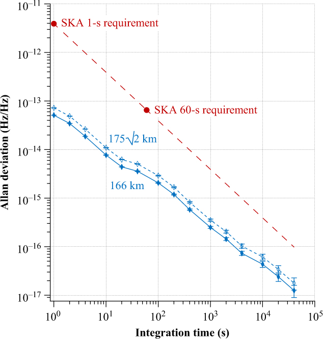
The most stringent use case of the SKA1-MID phase synchronisation system is synchronisation of two antennas each located at the end of separate 175 km links. To predict the coherence loss performance for this use case, the Allan deviation values for the 166 km measurements were first extrapolated to 175 km using the process described in Williams, Swann, & Newbury (Reference Williams, Swann and Newbury2008). The measured Allan deviation values are multiplied by (L2/L1)3/2, where L1 is the length of the measured link (166 km) and L2 is the extrapolated length (175 km). Secondly, to predict the stability between two independent systems, the extrapolated Allan deviation values were then multiplied by a factor of $\sqrt 2 $
.
$\sqrt 2 $
.
The Allan deviation measurement has a slope with a gradient close to τ− 1. This indicates that the dominant noise process affecting the stabilised frequency reference is white phase noise. An estimate of the coherence loss can therefore be calculated using the process described by Thompson, Moran, & Swenson (Reference Thompson, Moran and Swenson2017, p. 435) and Rogers & Moran (Reference Rogers and Moran1981). With this, a permissible Allan deviation upper limit value of 3.9×10⁻¹²/τ was calculated given the requirement of 1.9% coherence loss at the maximum observing frequency.
If the same coherence calculations are applied to the extrapolated Allan deviation values, the coherence losses are determined to be 7.41 × 10⁻⁶ and 7.96 × 10⁻⁶ at one second and 60 s of integration time respectively. This results in an excess of the coherence loss requirement by a factor of 2 560 at 1 s integration, and a factor of 239 at 60 s.
6.2 Phase drift performance
The phase drift performance was measured by mixing down the aforementioned 40 MHz out-of-loop measurement signal to DC using a stable 40 MHz LO. This 40 MHz LO was derived by frequency dividing the existing 80 MHz LO by a factor of 2. Both the RF and LO inputs of the mixer were band-pass filtered and the input powers were tuned to drive the mixer at its optimal level.
Temporarily using an independent RF input set at identical power level, but detuned from the LO by 50 kHz, revealed that the discriminator curve was approximated by an ideal sinusoidal shape, with a peak-to-peak range of 274 mV. This produced a phase-to-voltage discriminator with a gradient of 137 mV/rad, which is 99% linear within a range of ±53.4 mV (±0.39 rad).
With the measurement signal re-connected, the phase of the LO signal was adjusted using a variable delay line to centre the mixer DC output as close as possible to 0 V. This was necessary to ensure that any deviations would remain within the linear output range of the mixer.
With this initialisation process completed, the resultant DC signal was logged using an Agilent 34410A digital multimeter. The root mean square of the measured voltage data is 58 μV, so well within the linear range of the mixer. The recorded time-series values were converted to phase deviations using the discriminator value calculated above, and the resultant absolute phase time-series was then used to calculate the magnitude of phase drift for each 10-min period within the data set. The magnitude of phase drifts was tallied and the results are presented as a histogram in Figure 7.
Histogram of 10-min phase drift magnitude of the SKA1-MID phase synchronisation system shown with 1 μrad bins, as measured over a 166 km metropolitan fibre link (solid blue line). Also shown is the 1-standard deviation cut-off value of 14 μrad (dashed red line); the requirement is for <1 rad.
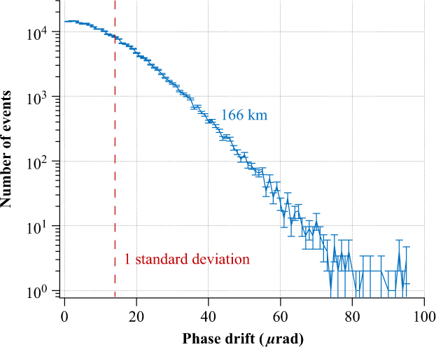
The 1-standard deviation value of 10-min phase drift of the SKA1-MID system deployed over a 166-km urban conduit optical fibre link is 14 μrad. There were no 10-min phase drift events greater than 100 μrad during the entire 15-h test period. The phase synchronisation system exceeds the 10-min phase drift requirement by almost five orders of magnitude.
6.3 Normal operating conditions
In addition to the above-mentioned baseline measurements, the transfer stability performance of the system was tested repeatedly over a wide range of normal operating conditions. The 1 and 60 s coherence loss, as well as the 10-min phase drift values were determined to exceed SKA performance requirements over all of the SKA-specified normal operating conditions outlined below. Further details of the particular experimental methods of each test and the associated specific performance values are outlined in the SKA1-MID Detailed Design Report (Schediwy & Gozzard Reference Schediwy and Gozzard2018). These normal operating conditions are stipulated according to the location of the equipment, with the defined locations being the CPF, the shelters (see Figure 1), and the pedestal at the antenna site. For a breakdown of the location of each equipment see Figures 3 and 4.
The specified operating conditions for temperature range are −5°C to +50°C at the antenna site and for the fibre link, and +18°C to +26°C for the CPF and shelters. The CPF equipment was tested in an environmental test chamber over a range of −8°C to +51°C; the shelter equipment between −8°C and +57°C, and the equipment in the CPF between +16°C and +30°C. During a two-week field deployment of the system on long-haul overhead fibre at the South African SKA site (Gozzard et al. Reference Gozzard, Schediwy, Wallace, Gamatham and Grainge2017b), the ambient temperature of the 186-km fibre link unfortunately ranged only between 0.9°C and 14.8°C (Gozzard et al. Reference Gozzard, Schediwy, Wallace, Gamatham and Grainge2017a).
The maximum temperature gradient is specified only for the antenna pedestal and fibre link. It is ±3°C over a 10-min period. Again an environmental test chamber was used for the equipment at the antenna pedestal, achieving maximum temperature gradients of at least +3°C and −13°C over a 10-min period. The maximum temperature gradient experienced by the 186-km fibre link during the field deployment was only ±1.2°C over 10 min.
The requirement for non-condensing relative humidity is between 40% and 60% at all locations. Test was conducted with all equipment exposed to a relative humidity range between 9% and 99%. The fibre link experienced a relative humidity between 21% and 97% during the field deployment. The final operating conditions specify that the system has to operate on overhead fibre with wind speeds up to 40 km per hour. During the field deployment, the system was operated and tested at wind speeds up to 50 km per hour.
In addition to the above normal operating conditions, a few other system properties were experimentally investigated. It is required that the system can survive seismic shocks up to 1 m/s2. This was verified by loading the equipment in a vehicle and subjecting the equipment to accelerations in all three axes at a variety of frequencies, including shock loads, up to 10 m/s2. Finally, the system was shown to exceed both the broadband and narrowband electromagnetic compliance requirements over the entire specified frequency range. The CFP equipment exceed specifications by a minimum of 27 dB for broadband, and 14 dB for narrowband emission, and the antenna hardware by a minimum 50 dB for broadband, and 37 dB for narrowband emission.
6.4 Additional design elements
The SKA1-MID telescope will employ a sample clock frequency offset scheme in order to assist with the mitigation of strong out-of-band radio-frequency interference and digitiser artefacts. The SKA1-MID phase synchronisation system will need to deliver the nominal MW-frequency reference signal to each antenna site with an offset determined by a unique integer multiple of 10 kHz. The system achieves this by simply commanding the DDS to apply the appropriate offset to the servo LO in each Transmitter Module . This then changes the control signal applied to the servo AOM which in combination with the fixed MW-frequency applied in the Microwave Shift module applies the appropriate offset to the frequency reference sent to the antennas.
The equipment in the CPF fits within two rack cabinets. The Optical Source , Microwave Shift , Frequency Source , Signal Generator , and Rack Distribution require 15 rack units (U) in total. In addition, the CPF equipment includes 14, 3 U-high Sub Racks , each of which house 16 Transmitter Modules ; 100-mm high, 580-mm deep Eurocard printed circuit boards (PCB). A few other rack units are dedicated to cooling, cable managements, network switches, and rack power supplies. The commercial bidirectional amplifiers in the repeater huts are 1 U. The optical and electronic components in the Receiver Module at the antenna site have a volume of less than 1.5 l. The equipment in the CPF requires 2.3 kW of electrical power. Each of the 14 bidirectional amplifiers in the repeater shelters or antenna pedestal requires no more than 50 W each. The Receiver Module is evaluated to require 5 W.
The MCU on each Transmitter Module is used to monitor the out-of-loop monitoring system and DC error signal, reporting the values to SAT.LMC at a cadence of once per second. The MCU is also used to command the DDS to adjust the servo LO frequency to the appropriate value required by the frequency offset scheme. Each type of module is designed to be hot swappable, and bespoke modules are constructed using mostly COTS components to help maximise maintainability, operability, and availability. All this is achieved with hardware costs of less than 10,000 per link.
7. Discussion
The SKA1-MID phase synchronisation system was designed specifically to meet the scientific needs and technical challenges of the SKA telescope. The system is able to optimise key design parameters while exceeding the performance needs of the SKA. The key innovation of SKA1-MID phase synchronisation system was finding a way to use AOMs as servo-loop actuators for modulated MW-frequency transfer (Gozzard et al. Reference Gozzard, Schediwy and Grainge2018b). This is important because AOMs have large servo bandwidths as well an infinite phase actuation range. This means that practical systems can be made extremely robust, as their servo loop will never require an integrator reset; this is a common problem encountered by most other techniques. Previously, AOMs had only been used as actuators for optical frequency transfer (Schediwy et al. Reference Schediwy, Gozzard, Baldwin, Orr, Warrington, Aben and Luiten2013; Ma et al. Reference Ma, Jungner, Ye and Hall1994).
For comparison, all ‘standard’ modulated frequency transfer techniques (Lopez et al. Reference Lopez, Amy-Klein, Lours, Chardonnet and Santarelli2010b), including ALMA’s (Shillue et al. Reference Shillue2012), require group-delay actuation to compensate the physical length changes of the fibre link. For practical deployments, this usually involves a combination of fibre stretcher (medium actuation speed and very limited actuation range) in series with at least one thermal spool (slow actuation speed and physically bulky). For the number of fibres, link distances, and servo loop actuation ranges encountered by the SKA, especially for SKA1-MID overhead fibre, which required actuation ranges hundreds of times greater than comparable-length underground fibre (Gozzard et al. Reference Gozzard, Schediwy, Wallace, Gamatham and Grainge2017b), standard modulated frequency transfer is totally impractical. A novel solution to this is to conduct the group delay in the electronic domain (Krehlik et al. Reference Krehlik, Śliwczyński, Buczek, Kołodziej and Lipiński2016); however, so far this has reportedly only been achieved using independent delay lines for the outgoing and return signals, thereby limiting the transfer performance below that of other leading techniques. Modulated ‘phase conjugation’ techniques (Primas, Lutes, Sydnor Reference Primas, Lutes and Sydnor1988) have also been successfully deployed over longer distances (He et al. Reference He, Orr, Baldwin, Wouters, Luiten, Aben and Warrington2013, Reference He2018) than standard modulated frequency transfer, and a particular implementation of this technique was selected as the phase synchronisation system for SKA1-LOW (Wang et al. Reference Wang, Zhu, Gao, Bai, Dong and Wang2015).
In addition, the AOMs generate frequency shifts to mitigate against unwanted reflections that are inevitably present on real-world links. This reflection mitigation strategy cannot intrinsically be implemented with modulated frequency transfer techniques, as the carrier and sidebands would be shifted by the same frequency. Therefore, these modulated transfer techniques require the returned signal to be rebroadcast at either a different modulation frequency, optical wavelength, or on a different fibre core, to avoid frequency overlap from unwanted reflections on the link. These reflection mitigating methods thereby reduce the symmetry between outgoing and returning signals, leading to degraded stabilisation performance, and can bring about additional complications, including those resulting from optical polarisation mismatch or from chromatic dispersion, which in turn requires further system complexity to overcome. However, reflection mitigation is essential for the SKA, as there is no way to guarantee that all links will remain completely free of reflections over the lifetime of the telescope.
The SKA1-MID system also benefits from being able to simultaneously suppress phase noise acquired on the fibre link and in the optical MZI contained within the CPF equipment (Schediwy et al. Reference Schediwy, Gozzard, Stobie, Malan and Grainge2017). This makes the equipment extremely robust to environmental perturbations, such as the vibration generated by the large number of cooling fans within the CPF. In contrast, the transmitter rack of the ALMA photonic system had to be specifically engineered to not use any cooling fans, and physically isolated from other telescope equipment.
Another innovation of the SKA1-MID phase synchronisation system is the use of a DPM in parallel with an AOM to generate the MW-frequency reference signal as a difference between two optical signals. Given the lower operating frequency of the SKA compared to ALMA (Shillue et al. Reference Shillue, AlBanna and D’Addario2004), the two optical signals can be generated using a single laser in combination with the DPM. This avoids the differential phase noise and complexity associated with offset locking a set of independent master and slave lasers as per the ALMA system. Another method of using a DPM to generate two (widely-spaced) optical frequencies was proposed (Kiuchi et al. Reference Kiuchi, Kawanishi, Yamada, Sakamoto, Tsuchiya, Amagai and Izutsu2007), but ultimately not adopted, as an alternative photonic system for ALMA (Kiuchi & Kawanishi Reference Kiuchi and Kawanishi2009). However, this technique still relied on group-delay actuation and would therefore be incompatible with the technique described in this paper.
Similarly, using a single radio-frequency source (the Frequency Generator ) to generate the reference signals for all independent Transmitter Modules avoids the phase drift that can occur even between two high-quality synthesisers (Gozzard et al. Reference Gozzard, Schediwy, Wallace, Gamatham and Grainge2017c). This is because for a synthesiser to maintain a constant output frequency relative to an input reference, it must change the phase of that output frequency signal as its internal temperature changes in response to variations in ambient temperature.
Another benefit of a technique that transmits only two optical signals is the avoidance of signal fading normally encountered with ‘standard’ and ‘phase conjugation’ techniques that use dual-sideband modulation (Foreman et al. Reference Foreman, Holman, Hudson, Jones and Ye2007). In these cases the chromatic dispersion of the fibre results in a differential evolution of phase of the two sideband-carrier products, resulting in periodic distances where the signal amplitude fades to zero amplitude. The SKA1-MID system intrinsically delivers the reference signal with maximum amplitude for any length of fibre.
Similarly, the use of FMs as reflectors for the remote site and MI reference arm (as opposed to using standard mirrors or circulators), ensures that the signals are always aligned in polarisation when combined on the local PD (Lopez et al. Reference Lopez, Amy-Klein, Lours, Chardonnet and Santarelli2010a). This avoids complexity and cost of a polarisation scrambler or polarisation alignment servo system (Lopez et al. Reference Lopez, Amy-Klein, Lours, Chardonnet and Santarelli2010b). Optical amplifiers are used for simply boosting signal strength of the optical signals without having to have the complexity of an optical–electronic–optical conversion typical in a full regeneration system (Gao et al. Reference Gao, Wang, Zhu, Yuan and Wang2015).
These advantages ensure that SKA1-MID phase synchronisation system can easily meet the functional performance requirements in practical realisation of the system while achieving maximum robustness, minimum cost, simple installation, and easy maintainability.
8. Conclusions
In this paper we have described the phase synchronisation system of the SKA1-MID telescope. Extensive testing has shown that the worst-case coherence loss for the SKA1-MID phase synchronisation system is 7.41 × 10⁻⁶ at 1 s second integration time, and 7.96 × 10⁻⁵ at 60 s integration time. These values exceed the 1.9% coherence loss requirement by a factor 2 560 and 239, respectively. Similarly, it was found that the system typically drifts in phase over a 10-min period by no more than 14 μrad, exceeding the phase drift requirement by almost five orders of magnitude.
The SKA1-MID phase synchronisation system can operate within specification over all required operating conditions, including temperature range, temperature gradient, and relative humidity. In addition, the system was operated on overhead fibre links longer than the maximum SKA1-MID distance, and at wind speeds up to 50 km per hour. Finally, the tests have also demonstrated seismic resilience and electromagnetic compliance.
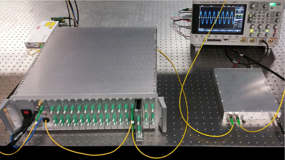
With the 4-year development period completed and the SKA1-MID phase synchronisation system having passed its Critical Design Review, work has now progressed to completing the mass-manufacture prototypes in readiness for SKA Construction (see Figure 8).
Photo of mass-manufacture prototypes of the SKA1-MID phase synchronising system. A Transmitter Module is shown protruding from the Sub Rack on the left, and the Receiver Module is shown on the right.
Author ORCIDs
S. W. Schediwy, https://orcid.org/0000-0001-9928-1364.
Acknowledgements
This paper describes work carried out for the SKA SADT consortium as part of the SKA project. The authors wish to thank Bassem Alachkar for useful discussions on interferometer coherence, and Thea Pulbrook for contributing to follow-up work stemming from the work reported here. Thanks also to AARNet for the provision of light-level access to their fibre network infrastructure.
The SKA project is an international effort to build the world’s largest radio telescope, led by the SKA Organisation, with the support of 12 member countries. This work was supported by funds from the University of Manchester and the University of Western Australia.


