
The rapidly evolving world of wireless communications is driven by the ever-ongoing enhancement of already existing services and the emergence of new services. This includes the usage of video-on-demand services such as ultra-high definition (UHD) television and 3D video (enhanced mobile broadband), which will continue to grow and account for a large portion of all mobile data traffic. Moreover, Mobile Internet (MI) and Internet of Things (IoT), including machine-to-machine (M2M), device-to-device (D2D) and human-to-machine (H2M) connectivity, will be major market drivers beyond 2020 and are expected to trigger a large range of use cases. Some of these emerging use cases will significantly contribute to increasing mobile data traffic. The rate at which applications are being adopted is thereby accelerating (application uptake). Another driving factor is the massive growing number of connections (connected devices) and the spread of smart mobile devices (device proliferation), smartphones, and tablets, but also other kinds of devices such as wearable and machine-type communication devices. This is running alongside a growing number of users/subscribers with an ever-increasing demand for flexibility, mobility, and higher user data rates. All these driving factors will lead to an explosion of data traffic in mobile communications [1]. To enable higher data rates and spectrum efficiency to cope with this data traffic explosion as well as to meet users’ demands for flexibility and mobility, various enabling techniques, technologies, and smart hardware solutions have to be developed and devised such as advanced modulation, coding and multiple access schemes, flexible backhaul and dynamic radio access configurations, flexible spectrum usage, flexible downlink/uplink resource allocation schemes, flexible (frequency-agile and environmental-agile) radio interfaces, as well as polarization- and space-agile antenna systems, including analog beam-steering and beam-forming antenna arrays as well as active and massive multiple-input–multiple-output (MIMO) antenna configurations.
Because of the huge spectrum availability in the millimeter-wave (mm-wave) frequency range from 30 GHz to 300 GHz, and connected with it, the feasible large bandwidths to meet the requirements for ever higher user data rates, mm-wave communication will be the next frontier in wireless technology, in particular for future fifth generation (5G) and beyond terrestrial as well as future satellite-based hardware platforms and infrastructures. The latter will include intrinsic multicast/broadcast and high-throughput satellites (HTSs) in the Ku-, Ka-, and V-bands, but also future non-geostationary orbit (NGEO) satellite fleets for real-time communication services. Consequently, one of the next evolutionary steps will be to form hybrid networks, combining satellite and terrestrial Internet Protocol version 6 (IPv6) connectivity, for example for connected, self-driving cars (Internet of Vehicles) and IPv6 on robotics, and later in the next generations of mobile communications systems, 6–8G [Reference Tripathi and Khaparde2]. Some of the HTSs and NGEOs operate or will operate below the mm-wave frequency range, for example from about 10 GHz to 30 GHz, that is, belonging to the microwaveFootnote 1 frequency range. This part of the spectrum is also considered in this book.
Sections 1.1 and 1.2 give an overview of the different communication platforms and infrastructure, depicting the evolution and trends in terrestrial and satellite-based mobile communications and technologies impacting emerging and future applications. These sections will also provide details about the driving factors behind these evolutionary processes, with facts and figures, including the major drivers influencing the growth of future mobile traffic; the 5G activities, vision, and objectives; the spectrum allocation schemes; the key technology drivers; the markets and perspectives; the evolving high-altitude platform stations (HAPSs); and trends of HTSs in geostationary and medium Earth orbits (GEOs and MEOs), as well as of low Earth orbit (LEO) HTS constellations, picturing also future interoperable satellite and hybrid terrestrial 5G satellite networks.
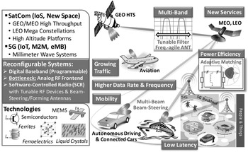
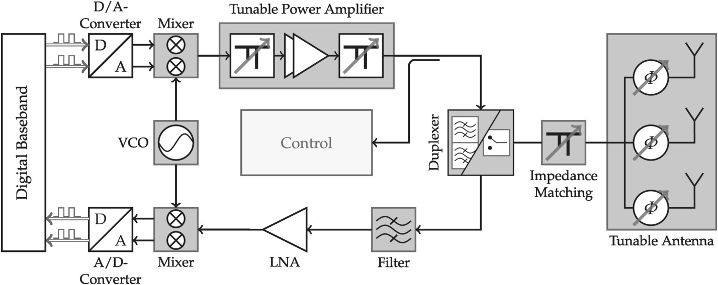
To integrate more and more users, services, and standards, and related to this, more and more frequency bands over a wide frequency range, as well as to enable broadband access, for example to internet, and at the same time, high energy efficiency, future generations of mobile communication systems require much higher flexibility for multiservice, multistandard, and multiband operation than in state-of-the-art systems. While reconfigurable architecture in the digital baseband already allows this flexibility for multiservice and multistandard operation, using powerful field-programmable gate arrays (FPGAs), controllers, and analog to digital converters with high dynamic and high speed, it has not yet been achieved in the analog radio frequency (RF) front end. There, up to now, multiband operation is often realized by individual transceivers for each frequency band. However, parallel implementation of transceivers means higher cost as well as larger space and volume, and in addition, higher overall energy consumption and hence less efficiency, in particular for the high-power amplifiers in the transmitter branches. Hence, frequency-agile RF front-end components such as filters, antennas, or impedance matching networks, tuning its center frequency over a wide frequency range or changing its bandwidth and/or impedance on demand and controlled by software would enable compact and smart frequency-agile, software-controlled radios. However, these approaches require new system concepts and corresponding innovative technological solutions for hardware with high integration density and low power consumption, in particular for hand-held devices. Another technological challenge in mm-wave mobile communications, in particular for relatively long distances, are electronic beam-steering or even beam-forming, high-gain antennas to enable flexible and reliable line-of-sight (LOS) communications.
High-gain, narrow-beam antennas are desired because of the following physical imperative: as the operational frequency increases, the free-space path loss increases at least quadratically, resulting in a stringent link budget. Moreover, utilizing a larger amount of bandwidth results in a higher amount of received noise power. Both effects lead to a significantly reduced signal-to-noise ratio (SNR) for a given communication distance, making mm-wave communication scenarios quite different from existing approaches in the radio-frequency and microwave ranges. The reduced SNR can be circumvented by increased equivalent isotropic radiated power (EIRP), which can be achieved by large output power of the transmitter’s power amplifier and by high-gain antennas. However, it is a challenge to obtain high transmit power in the mm-wave range no matter which device technology is chosen; therefore, such systems are typically built upon high-gain, narrow-beam antenna array architectures, utilizing electronic polarization agility, beam-steering, beam-forming, or adaptive spot-beam capabilities. This would enable flexible and reliable LOS mm-wave communications for wireless backbones and small cells such as micro-, pico-, and femtocells in cellular networks or for mobile users of satellite systems.
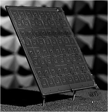
A first introduction and overview of concepts and technologies to implement these smart system functionalities is provided in Section 1.3, including the software-defined and software-controlled radio approaches; examples of reconfigurable/tunable RF components and circuits; various technologies to enable suitable low-cost, robust, and reliable hardware solutions suited for smart mm-wave systems; and different electronically steerable antenna (ESA) concepts, introducing also approaches of various spin-off companies for producing and commercializing low-profile, cost-efficient large-scale ESAs.
1.1 Evolution of Mobile Communications
Since the 1990s, mobile communication has become a most significant platform, leading to a revolutionary transformation in the way to communicate, experience entertainment, and make use of the Internet, driven by users’ demands for mobility and tremendous amount of growth in connectivity and data traffic volume. Since these trends are evolving dramatically, we are now at the dawn of a new era in mobile communications, aiming to overcome limits of state-of-art systems toward innovative mobile broadband applications and to meet new and unexpected demands beyond the capability of previous generations of systems to provide a mobile and everywhere-connected society [Reference Xiang, Shen and Zheng3, 4]. Since the sociotechnical evolution in the past decades has been significantly driven by this evolution of mobile communications, which has been closely integrated in the daily life of all of society, it is expected that both will remain tightly coupled, forming an even stronger foundation for society beyond 2020 [4]. Figure 1.1 illustrates the evolution in mobile communications, that is, all evolving generations that use a licensed spectrum, including the future 5G. Wireless technologies that are using an unlicensed spectrum (nomadic) such as WiFi, Bluetooth, and WiMAX will not be considered. During the process of evolution in mobile communications, the data rate, mobility, coverage, and spectral efficiency generally increase.
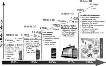
Figure 1.1 Evolution in mobile communications with some characteristics of the various generations.
It all started in 1979 with the foundation of the first cellular mobile communication systems by NTT in Japan. These 1G cellular mobile communication systems were focused on basic voice service with analog-based protocols, using most often frequency modulation (FM) and frequency division multiple access (FDMA) schemes. A unique feature was the use of first cellular networks built up of hexagonal cells. Data rates were up to 2.4 kbit/s, but often accompanied with some drawbacks such as unreliable handoff and poor voice links. Major standards were the Advanced Mobile Phone System (AMPS), Nordic Mobile Telephone (NMT), and Total Access Communication System (TACS) [Reference Tripathi and Khaparde2, Reference Rafay5].
The first digital standards were developed in the 1990s in the second generation of mobile communications with additional voice capacity and improved coverage and mobility. Standards were Global Systems for Mobile communications (GSM), IS-54 TDMA (Time Division Multiple Access), IS-95 CDMA (Code Division Multiple Access), and the Personal Access Communications System (PACS). Beyond voice communication, 2G also provided services such as Short Message Service (SMS) and email. Data rates were up to 64 kbit/s. 2G-mobile handset battery lasted longer, because radio signals have low power. 1G and 2G used a circuit-switched, connection-based technology, where the end systems are devoted for the entire call period, having low efficiency in the usage of bandwidth and resources and inability to handle complex data such as video. In 2.5G, packet switching was applied along with circuit switching, supporting high data rates up to 144 kbit/s. The main technologies were General Packet Radio Services (GPRS) and Enhanced Data rate for GSM Evolution (EDGE) [Reference Tripathi and Khaparde2, Reference Rafay5]. While 1G and 2G technologies used a circuit-switched, connection-based technology, where the end systems are devoted for the entire call period, 2.5G and 3G used both circuit and packet switching, and the next generations from 3.5G to 5G use packet switching.
3G was established with the first commercial network of NTT DoCoMo in October 2001 in Japan, merging high-speed mobile access to services based on Internet Protocol (IP). It allowed transmission rates of up to 2 Mbit/s for fixed applications in local coverage areas, enabling video calls and video conferences, and 144 kbit/s to 384 kbit/s for mobile applications in wide coverage areas. Beside improved voice quality, it provided global roaming for the first time. However, 3G handsets often required more power than most 2G models. Since 3G utilized Wideband Code Division Multiple Access (WCDMA), Universal Mobile Telecommunications Systems (UMTS) and Code Division Multiple Access (CDMA) 2000 technologies, evolving technologies such as High Speed uplink/downlink Packet Access (HSPA) and Evolution-Data Optimized (EVDO) made an intermediate wireless generation 3.5G with improved data rates of 5–30 Mbit/s, allowing downloading of huge files in less time. The peak upload rate was 5 Mbit/s and the peak download rate is 100 Mbit/s [Reference Tripathi and Khaparde2, Reference Rafay5, Reference Mitra and Agrawal6]. Thus, 3G was the first mobile broadband standard.
After the introduction of Long-Term Evolution (LTE) technology and Fixed Worldwide Interoperability for Microwave Access (WiMAX) already during the 3G evolutionary period, subsequent LTE-Advanced (LTE-A) as a forthcoming 4G standard along with mobile WiMAX, developed in the 2010s, provided a substantial number of users with faster and better mobile broadband services such as video-on-demand, peer-to-peer file sharing and composite web services, Multimedia Messaging Service (MMS), Digital Video Broadcasting (DVB), and video chat as well as high-definition TV and mobile TV. Thus, 4G truly constitutes mobile broadband. All this is possible because a supplementary spectrum is accessible and operators manage their network more efficiently, offering better coverage with improved performance such as higher throughput and spectral efficiency for lower cost, and most decisively, the prevailing communication networks could be improved by imparting a complete and reliable solution based on IP, where the 128-bit IP version (IPv6) replaces the 32-bit IP version (IPv4), supporting a high quality of services, security, and mobility [Reference Rafay5, Reference Mitra and Agrawal6].
4G uses orthogonal frequency division multiplexing (OFDM) and ultra-wide band radio (UWB). The frequency range is between 2 and 8 GHz with a bandwidth of 100 MHz and data rates of 20 Mbit/s up to 1 Gbit/s, where the peak upload and download speed may be up to 500 Mbit/s and 1 Gbit/s, respectively. Mobile speed can be up to 200 km/h. The high performance is achieved by the use of long-term channel prediction, in both time and frequency, scheduling among users, and multiple antennas combined with adaptive modulation and power control. First efficient software-defined radios (SDRs) are introduced, where the radio can be configured or defined by software. Primarily, SDR benefits from the high processing power, enabling multistandard and multiband operation, and where terminals will adapt the air interface to the available radio access technology [Reference Tripathi and Khaparde2]. Although 4G connections represented only 26% of all mobile connections, 4G traffic already accounted for 69% of all mobile traffic in 2016, while 3G connections represented 33% and only 24% of all mobile traffic. Thus, a 4G connection generated four times more traffic on average than a 3G connection [7].
To cope with this exponential increase in mobile data traffic and smart device connections in the future, but also to meet the network operators’ and users’ demands for flexibility and mobility as well as for enhanced and new services and applications, often requiring significant higher data rates, and hence, bandwidth, the next major phase in the evolution of mobile communications is upcoming, named 5G. 5G is considered as beyond 2020 mobile communications technology, supporting IPv6 and flat IP, where it is commonly assumed that 5G cellular networks face some challenges that are not effectively addressed by 4G: higher capacity, higher data rate, lower end-to-end latency, massive device connectivity, reduced cost, and consistent quality service (QoS) provisioning. Recently introduced IEEE 802.11ac, 802.11ad, and 802.11af standards are acting as building blocks on the road toward 5G [Reference Rafay5].
1.1.1 Major Drivers Influencing the Growth of Future Mobile Traffic
The evolution of wireless communications is driven primarily by the anticipated data traffic explosion and its economical perspective. Many white papers and reports present some of the major global data traffic projections and growth trends. According to the CISCO White Paper [7], the forecast for global mobile data traffic per month ranges from about 7 EB to 49 EB between 2016 and 2021, which means a compounded annual growth rate (CAGR) in the overall mobile data traffic of 47% from 2016 to 2021. The key figures in [8] are quite similar: the total mobile data traffic is estimated as 8.5 and 69 EB/month in 2016 and 2022, respectively, with a CAGR of 45% compared to 70 and 170 EB/month for the total fixed data traffic in 2016 and 2022, respectively, with a CAGR of 20%. Better user experience and lower prices of “smart” devices will accelerate its proliferation. Thus, the projected IPv6 mobile traffic forecast will increase over the same time period from 1.03 EB in 2016 to 27.4 EB in 2021, which means an increase from 14.7% to 56% of the total mobile traffic noted earlier. The CAGR in IPv6 network traffic is then 92% from 2016 to 2021 [7].
Some drivers and trends that impact traffic growth are described in detail in Report ITU-R M.2370 [1], containing global International Mobile Telecommunications (IMT) traffic estimates beyond 2020 from several sources, where the global mobile traffic estimates per month beyond 2020 with and without M2M traffic are illustrated in Figure 1.2. These traffic estimates are significantly higher than those of the aforementioned White Paper [7] for 2020 and 2021. They reach 62 EB/57 EB, 607 EB/543 EB, and 5016 EB/4394 EB with and without M2M traffic in 2020, 2025, and 2030, respectively. This means a CAGR of around 55% and 54% in 2020–2030 with and without M2M traffic, respectively. These estimates anticipate that global IMT traffic will grow in the range of 10–100 times from 2020 to 2030 [1].
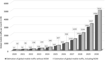
Figure 1.2 Mobile traffic estimates per month in EB between 2020 and 2030 without and with M2M traffic. All data values are taken from [1]. The network capacity unit ExaByte is 1018 bytes.
Among many characteristics and trends that are expected to impact the anticipated traffic growth and the overall traffic demand in 2020 and beyond, there are three major drivers influencing the growth of future mobile traffic [1]:
▪ Enhanced mobile broadband, in particular by video usage
▪ Application uptake, that is, the rate at which applications are being adopted
▪ Device proliferation, accompanied with an evolution toward ever smarter mobile devices in different form factors and with continuously enhanced capabilities and intelligence, which require increasing bit-rates and bandwidth
All are expected to evolve over time.
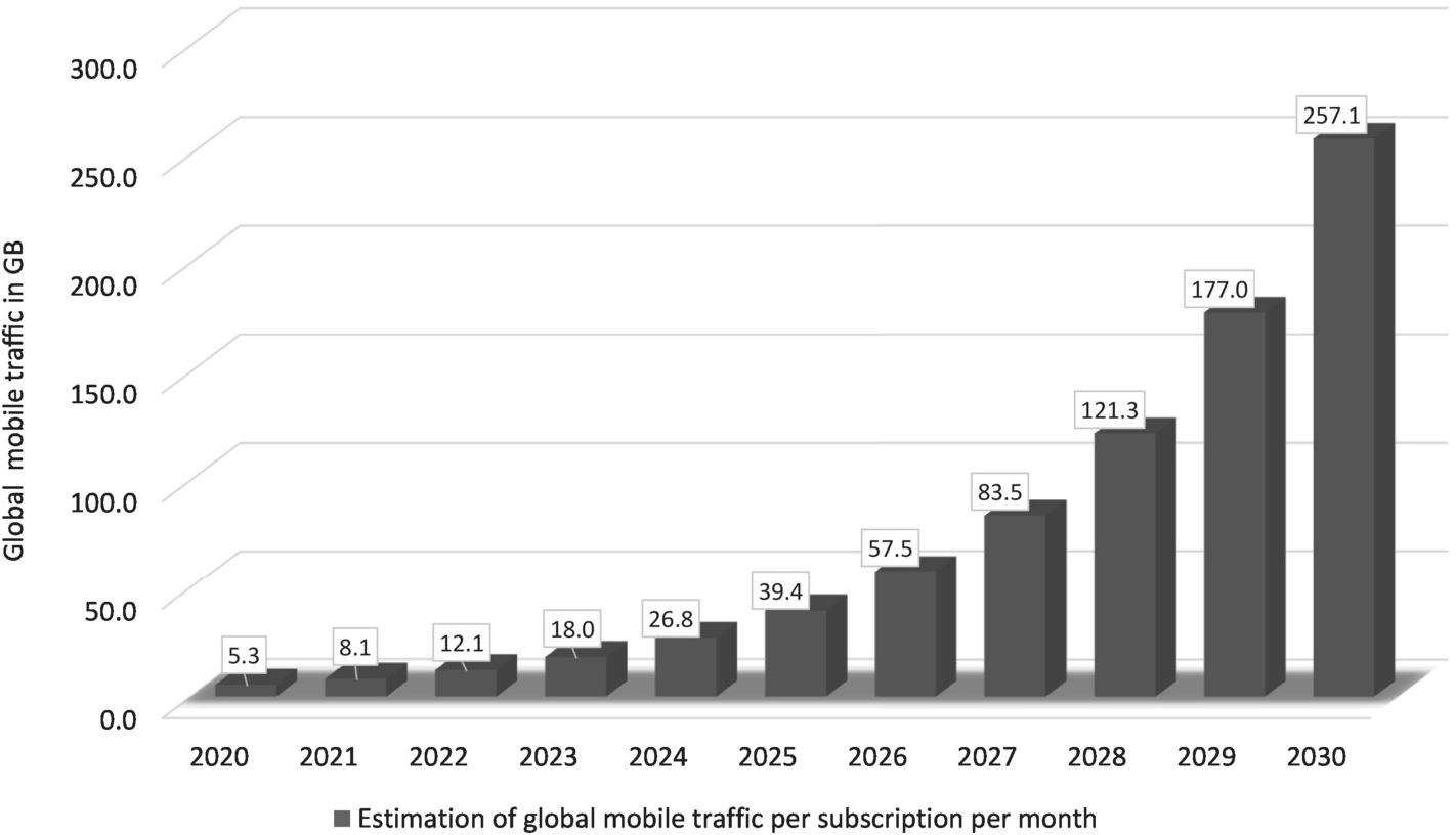
Within the different service types behind this anticipated traffic growth is M2M with a traffic volume of about 7% and 12% of the total in 2020 and 2030, respectively [1]. By far the largest traffic volume will be consumed by the usage of video-on-demand services (video usage), which will continue to grow, and resolution of these videos will continue to increase. Beyond 2020, people will watch more ultra-high-resolution audio-visual content, regardless of the way the content is delivered. Video streaming with an enhanced mobile broadband is expected to account for almost 75% of all global mobile traffic in 2021, being 4.2 times and 6 times higher than non-video in 2025 and 2030, respectively [1]. The popularity of ultra-high resolution and large screens as well as the increasing number of high-performance smart devices such as smartphones and tablets, widely used around the world, together with the growth of mobile subscriptions will dramatically increase the mobile traffic volume consumed by each user according to Figure 1.3. The figure indicates that each subscriber will consume 5.3 GB, 39.4 GB, and 257.1 GB of data traffic per month on average in 2020, 2025, and 2030, respectively.

Figure 1.3 Estimations of global mobile data traffic per subscriptions per month from 2020 to 2030 without M2M traffic. All data values are taken from figure 10 in [1]
Moreover, the rate at which applications are being adopted by users is accelerating. The annual global downloading of applications was 102 billion apps in 2013 and grew to about 270 billion in 2017. This mobile application uptake and usage of applications will contribute to increased mobile broadband traffic [1] and the broadband access growth rates given by various laws.
Nielsen’s Law of Users’ Internet Bandwidth, that is, users’ internet connectivity in bits per second, is based on data from 1983 to 2016. It states that high-end users’ connection speed grows by 50% per year, reaching 120 Mbit/s and 240 Mbit/s in 2014 and 2016, respectively [Reference Nielsen9]. This means it doubles roughly every 21 months. This 50% CAGR is close to the more established Moore’s Law, which states that computers double in capabilities every 18 months, which corresponds to about 60% annual growth. An observation similar to Nielsen’s has been made by Ulm et al. in [Reference Ulm, Cloonan, Emmendorfer, Finkelstein and Fioroni10]. It reflects a 50% CAGR for the downstream and about 30% CAGR for the upstream capacity, respectively. Similar exponential curves, that is, fitted straight lines of data rates plotted logarithmically against time, can be found for the wireline, wireless (cellular), and nomadic (WLAN) technologies according to Edholm’s Law of Bandwidth. Some trends can be observed from the figures of data rates plotted logarithmically against time [Reference Fettweis and Alamouti11–Reference Cherry13]:
▪ Backhaul network bandwidth (wireline) is larger than the ones for cellular (wireless) and WLAN (nomadic) technologies. For example, in 2010, data rates of cellular connections were around 10 Mbit/s, for WLAN connections at about 1 Gbit/s, and for Ethernet connections of office desktops about 10 Gbit/s.
▪ Backhaul network bandwidth grows annually at 20–30%, while the bandwidth of wireless and nomadic technologies exhibits a 50% CAGR according to Nielsen’s Law.
▪ Since wireless and nomadic data rates are growing much faster than wireline ones, the curves will converge sometime in the future.
▪ Wireless and nomadic bandwidth lines are almost parallel with a gap in between of about 100 times, however, gradually converging and cutting at around 2030. This is because use cases for mobile data on devices will converge. Consumers only care about applications and services, not about the underlying network; thus a truly heterogeneous network is needed, leading to a new inflection point of technology [Reference Fettweis and Alamouti11].
Because the highest data speed offered is a determining factor for sizing the network, some open questions arise [Reference Ulm, Cloonan, Emmendorfer, Finkelstein and Fioroni10]: will this broadband demand for wireless and nomadic technologies end, that is, Nielsen’s Law break as Moore’s Law or will service providers offer a residential 10+ and 100+ Gbit/s Internet service by 2025 and 2030, respectively, according to Nielsen’s Law?
As mentioned earlier, another driving factor is the device proliferation accompanied with an evolution toward ever smarter mobile devices in different form factors and with continuously enhanced capabilities and intelligence, which require increasing bit-rates and bandwidth. Globally, the growth of wireless devices, accessing mobile networks worldwide, grew to 8.0 billion in 2016, and it will grow to 11.6 billion by 2021 at a CAGR of 8%, where 8.3 billion will be handheld or personal mobile-ready devices and 3.3 billion M2M connections according to the 2017 CISCO White Paper [7]. Again, the values for the personal mobile-ready devices are close to the one in [8]. The growth of global mobile subscriptions between 2020 and 2030 was estimated in 2015 by the International Telecommunication Union [1], where the values in 2020 and 2021 are higher than the ones of the aforementioned CISCO Report. It estimated the following number of global mobile subscriptions: 10.7 billion in 2020, 13.8 billion in 2025, and 17.1 billion in 2030, respectively. This is illustrated in Figure 1.4, together with the estimated number of mobile connected M2M devices, which would be around 7 billion in 2020, 34 billion in 2025, and 97 billion in 2030, respectively. Hence, it is expected that the total number of devices connected by global mobile communications networks will surpass 100 billion by 2030, which will be more than 10 times greater than the world population at that time, which was estimated at 7.52 billion in July 2017, 7.76 billion in July 2020, 8.14 billion in July 2025, and 8.5 billion in July 2030 [14].
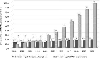
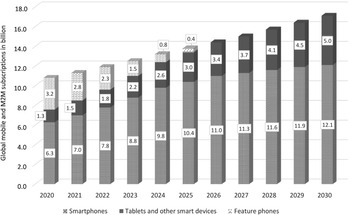
Figure 1.4 Estimations of global mobile and global M2M subscriptions in billions between 2020 and 2030 (top). In addition, the global mobile subscriptions are separated into three categories (bottom). All data values are taken from [1]
Better user experience and lower prices of smart devices will accelerate the growth rate of the penetration of smart devices. Thus, concerning the share of total devices, there will be a rapid decline of non-smartphones or feature phones from about 40% (3.3 billion) in 2016 down to 13% (1.5 billion) in 2021. At the same time, the share of smartphones, including phablets, will increase from about 45% (3.7 billion) in 2016 up to 53% (6.1 billion) in 2021. The shares of tablets, PCs, and other smart devices will smoothly go up from 4% in 2016 to 5% in 2021, while a noticeable growth is expected in M2M connections with shares of 10% in 2016 to 29% in 2021 [7]. Again, the estimation of global mobile subscriptions, separated for feature phones, smartphones, tablets, and other smart devices between 2020 and 2030 from [1], is given in Figure 1.4.
1.1.2 5G Activities, Vision, and Objectives
The framework, the overall objectives, and timelines of the development of IMT, including user and applications trends, usage scenarios and capabilities, technology trends and technical feasibility, traffic growth estimation, and spectrum implications as well as the expected evolution is regularly defined and released in Recommendations of the International Telecommunication Union (ITU), offering at the time of its publication some visions of future systems and networks. The most important ones for mobile communications are taken as basic references for this book chapter.
The Recommendation for IMT-2000 in 2000 [15] provides a single set of standards for 3G, which marks a major change in cellular mobile communications evolution. Based on IMT-2000 (3G), the ITU has released Recommendation ITU-R M.2012 in the terrestrial radio interface of IMT-Advanced in 2012, after nine years for its development, where 4G specifications are based on the IMT-Advanced requirements. Along with the enhancement of IMT-2000 (3G) and IMT-Advanced (4G) systems, a new IMT vision was released in 2015 [4], defining the framework and overall objectives of the development of future radio interfaces with far more enhanced and new capabilities of IMT in 2020 and beyond, called IMT-2020 (5G).
In parallel, different activities, involving academic research groups and telecommunication companies, have worked on or are still working on 5G scenarios, test cases, new system concepts, network architectures, and technologies, influencing the standardization and regulatory processes. A brief overview over some activities is given in [Reference Mitra and Agrawal6]. An example is the largest 5G project METIS (Mobile and wireless communications Enablers for the Twenty–twenty Information Society) within the Framework Program 7 (FP7) of the European Union, where top telecommunication companies and top academic institutions have been evolved. Their comprehensive outcomes are summarized in the METIS final project report in 2015 [16] (Deliverable D8.4), based on in total 29 deliverables, including scenarios, requirements, and key performance indicators for 5G mobile and wireless system (D1.1), channel models (D1.2, D1.4), test-bed/demonstration results (D1.3), requirements and general design principles for new air interface (D2.1), novel radio link concepts and state of the art analysis (D2.2), components of a new air interface-building blocks and performance (D2.3), proposed solutions for new radio access (D2.4), multi-node/multi-antenna transmission technologies (D3.1, D3.2, D3.3), network-level solutions (D4.1, D4.2, D4.3), spectrum needs and usage principles (D5.1, D5.3, D5.4), METIS system concept and technology roadmap (D6.6), and architecture and system evaluation results (D6.4, D6.3). In the subsequent METIS-II project (https://5g-ppp.eu/metis-ii/), the key objectives have been
to develop an overall 5G radio access network design and to provide the technical enablers needed for an efficient integration and use of the various 5G technologies and components currently developed. On the strategic level, METIS-II provided the 5G collaboration framework with the 5G-PPP (5G Infrastructure Public–Private Partnership) for a common evaluation of 5G radio access network concepts and prepare concerted action towards regulatory and standardization bodies.
Stimulated by the METIS outcome and on the aforementioned 5G/IMT – 2020 Report [4], Wei Xiang et al. published a comprehensive book in 2017 [Reference Xiang, Shen and Zheng3], in which a large number of authors have been involved, revealing the enabling techniques for 5G networks and addressing the challenges and opportunities of 5G mobile communications.
Based on these three major literatures on 5G, its vision is briefly summarized in the text that follows, starting with the major market drivers beyond 2020, which is expected to be MI and IoT, including M2M or D2D connectivity [Reference Xiang, Shen and Zheng3, 4]. Both MI and IoT will trigger a massive number of use cases, for example
▪ Mobile Internet (MI): Ultra-high density (UHD) and 3D video, augmented reality, virtual reality, online gaming, mobile cloud, remote computing, tactile Internet, 3D connectivity to aircrafts and drones, collaborative robots, smart office, as well as
▪ Internet of Things (IoT): Smart grid and critical infrastructure monitoring, mobile surveillance, environmental monitoring, industrial automation, eHealth services, smart wearables and smart body area networks, sensor networks, smart homes/buildings, smart cities, smart transportation, self-driving and connected cars (Internet of Vehicles).
All these use cases can be grouped into three usage scenarios [Reference Xiang, Shen and Zheng3, 4] or generic 5G services [16], addressing different use case characteristics according to Figure 1.5:
▪ Enhanced/extreme mobile broadband (eMBB) for improved performance and an increasingly seamless user experience, offering human-centric use cases for access to multimedia services at least with IMT capabilities (see Table 1.1)
▪ Massive machine-type communications (mMTC) characterizes a large number of connected devices, typically with relatively low-volume, non-delay sensitive data at low cost and very long battery lifetime
▪ Ultra-reliable and low-latency communications (URLLC) with stringent requirements for capabilities such as throughput, latency, and availability for applications such as industrial process monitoring and manufacturing, remote medical diagnosis and surgery, as well as safety and automation in smart grids.

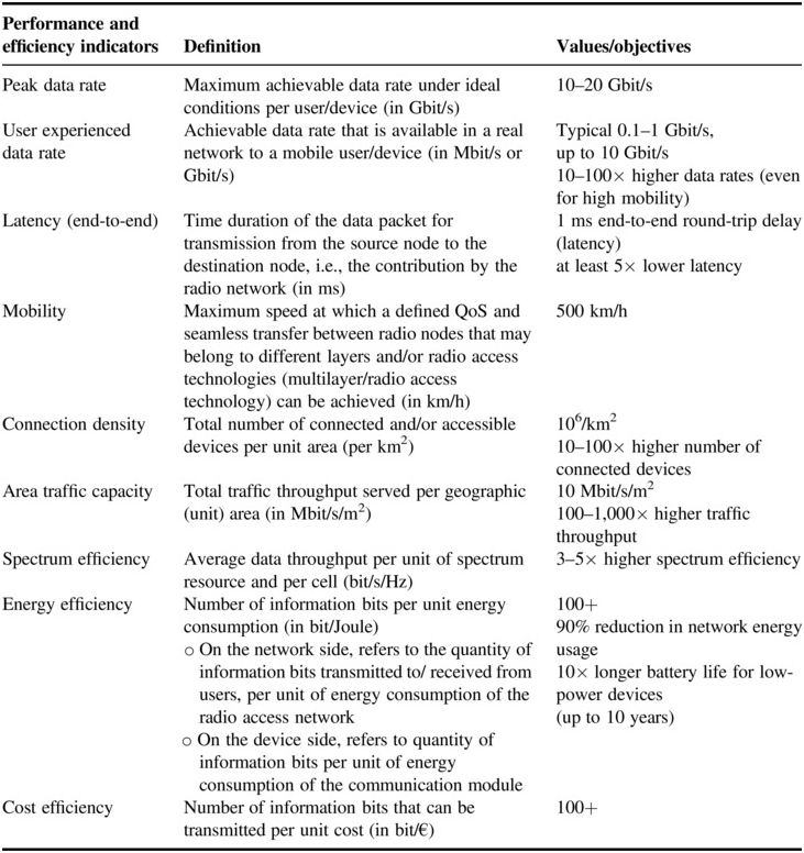
Table 1.1 Key capabilities or key performance parameters for 5G/IMT-2020 according to [Reference Tripathi and Khaparde2–4, 16]
| Performance and efficiency indicators | Definition | Values/objectives |
|---|---|---|
| Peak data rate | Maximum achievable data rate under ideal conditions per user/device (in Gbit/s) | 10–20 Gbit/s |
| User experienced data rate | Achievable data rate that is available in a real network to a mobile user/device (in Mbit/s or Gbit/s) | Typical 0.1–1 Gbit/s, up to 10 Gbit/s 10–100× higher data rates (even for high mobility) |
| Latency (end-to-end) | Time duration of the data packet for transmission from the source node to the destination node, i.e., the contribution by the radio network (in ms) | 1 ms end-to-end round-trip delay (latency) at least 5× lower latency |
| Mobility | Maximum speed at which a defined QoS and seamless transfer between radio nodes that may belong to different layers and/or radio access technologies (multilayer/radio access technology) can be achieved (in km/h) | 500 km/h |
| Connection density | Total number of connected and/or accessible devices per unit area (per km2) | 106/km2 10–100× higher number of connected devices |
| Area traffic capacity | Total traffic throughput served per geographic (unit) area (in Mbit/s/m2) | 10 Mbit/s/m2 100–1,000× higher traffic throughput |
| Spectrum efficiency | Average data throughput per unit of spectrum resource and per cell (bit/s/Hz) | 3–5× higher spectrum efficiency |
| Energy efficiency | Number of information bits per unit energy consumption (in bit/Joule)
| 100+ 90% reduction in network energy usage 10× longer battery life for low-power devices (up to 10 years) |
| Cost efficiency | Number of information bits that can be transmitted per unit cost (in bit/€) | 100+ |
The third column indicates values/objectives and improvements compared to 4G/IMT-Advanced.
While MI is focused on people-oriented communications, IoT provides communications between things and between things and people. Some of its use cases are indicated in Figure 1.5. UHD and 3D videos, over-the-top services such as social networking, as well as desktop cloud, augmented reality, and online gaming will significantly drive up data rates, even at high mobility in high-speed trains and connected cars (Internet of Vehicles), where massive data activities of a vast number of users will require a high system capacity. For services such as smart homes, smart cities, as well as environmental monitoring, future networks have to support massive connectivity of devices with low energy and cost. While some use cases such as desktop cloud, augmented reality, and online gaming will additionally need “imperceptible” latency, “safety-critical” use cases such as e-banking, eHealth, self-driving cars, smart grid, and critical infrastructure monitoring face extreme security requirements, that is, in fast response with very low latency in the lower millisecond range and with nearly absolute reliability and perception of 99.999% availability [Reference Tripathi and Khaparde2–4, 16].
It is expected that 5G/IMT-2020 will provide far more enhanced capabilities than 4G/IMT-Advanced, defining nine key performance and efficiency indicators summarized in Table 1.1.
Among these key capabilities, the user experienced data rate, connection density, and latency might be the most fundamental ones. While all key capabilities may to some extent be important for most of the aforementioned use cases, the relevance of certain key capabilities may be significantly different for the individual use cases or usage scenarios [Reference Xiang, Shen and Zheng3, 4, 16]. In these references, the importance of key capabilities for the three usage scenarios are given in form of a “spider-web” and “blooming flower” pictures together with some explanations, and in addition, the enhancement of key capabilities from 4G/IMT-Advanced to 5G/IMT-2020.
Compared to 4G, 5G should have three to five times higher spectrum efficiency and more than 100 times improvement on energy and cost efficiency to outperform previous generations of mobile communications systems. Moreover, to keep up with the rapid traffic growth, some core design objectives of 5G wireless networks are [Reference Tripathi and Khaparde2–4, 16, 17]:
▪ Implementation of massive (up to 1,000-fold) area traffic capacity (see Table 1.1) and massive device connectivity for at least up to 100 billion devices according to the predictions in Figure 1.4.
▪ Providing a fiber-like user experienced data rate by 10–100 times (see Table 1.1), that is, of up to 10 Gbit/s, for example, to support mobile cloud service, capable of extremely low latency and response times.
▪ Support for an increasingly diverse set of services, applications, and users – all with extremely diverging requirements as discussed earlier for the usage scenarios.
▪ Flexible and efficient use of all available noncontiguous spectrum for wildly different network deployment scenarios, which will be described in the next section.
1.1.3 Spectrum Allocation
To cope with the anticipated 1,000 times higher traffic capacity and the up to 100 times higher typical user data rate in 5G wireless networks, considerably more spectrum is required than currently available for mobile and wireless communication systems. Hence, in the 5G vision, another significant driver is the vast amount of spectrum available in the mm-wave range [Reference Xiang, Shen and Zheng3, 16, 18–20], for example, for cellular hot-spot coverage to satisfy consumer demand for high-speed wireless access with ultra-low latency. Technical feasibility of radio interface technology and systems operating in frequency bands between 6 GHz and 100 GHz, considering propagation characteristics, antenna technology, active and passive components, physical layer, and medium access control design as well as deployment architectures, is carried out by simulations and performance tests and trials and are published in [18, Reference Rappaport, Heath, Daniels and Murdock19, Reference Rappaport21].
Spectrum has been in the past and will also be in future one of the most valuable resource for mobile communications. Therefore, agencies and standardization organizations worldwide aim for international harmonized spectrum and full-spectrum access, especially above 6 GHz. Hence, beyond the sub-6 GHz bands for 5G in Europe 3.4–3.8 GHz, USA 3.1–3.55 GHz and 3.7–4.2 GHz, Japan 3.6–4.2 GHz and 4.4–4.9 GHz and China 3.3–3.6 GHz, 4.4–4.5 GHz and 4.8–4.99 GHz for 5G phase I, frequency bands in the mm-wave range are already foreseen for 5G phase II: in Europe 24.25–27.5 GHz and 31.8–33.4 GHz, United States 27.5–28.35 GHz and 37–40 GHz, Japan 27.5–29.5 GHz, China 24.75–27.5 GHz, South Korea 26.5–29.5 GHz. Moreover, some studies and tests are carried out by Samsung at 13.4–14 GHz, 18.1–18.6 GHz, 27.0–29.5 GHz, and 38.0–39.5 GHz. China allocated 40.5–42.5 GHz and 48.4–50.2 GHz for fixed point-to-point wireless access systems as well as 42.3–47.0 GHz and 47.2–48.4 GHz for mobile point-to-point wireless access systems [Reference Xiang, Shen and Zheng3].
In the V-band, a continuous spectrum is allocated for wireless communications in unlicensed mode: 57–64 GHz in the United States, 57–66 GHz in Europe, 59–64 GHz in China, and 59–66 GHz in Japan [Reference Xiang, Shen and Zheng3, Reference Rappaport, Heath, Daniels and Murdock19, 20]. In Europe, the European Telecommunications Standards Institute (ETSI) is working to facilitate the use of the E-band from 71.0 to 76.0 GHz and 81.0 to 86.0 GHz, and in the future, on the channelization of the W-band from 92.0 to 114.5 GHz and the D-band from 130.0 to 174.8 GHz for large-volume (high capacity) backhaul and front-haul systems as well as for innovative solutions for fixed broadband access [20].
Most of the GEO- and MEO-HTS make efficient use of both, Ku-band and Ka-band (e.g., O3b downlink 17.7–20.2 GHz, uplink 27.5–30 GHz). LEO high-throughput satellite constellations also aiming to operate in the Ku-, Ka- and V-bands.
International harmonized spectrum and spectrum regulation will support future mobile network implementation and other services, enabling large-scale usage of the spectrum. Parts of the aforementioned bands do not have global mobile allocation, and since several other services such as different satellite services, radiolocation, and radionavigation will use portions of these bands, some compatibility studies to determine the feasibility of using these bands must be discussed and managed on a global level, for example at World Radiocommunication Conferences [Reference Martin, O’Keefe and Finucan22].
1.1.4 Key Technology Drivers
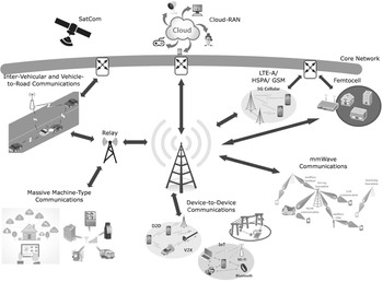
The deployment of 5G networks is expected to emerge between 2020 and 2030. In [Reference Tripathi and Khaparde2-4, 16, 17] different deployment scenarios and environments are considered in detail such as various indoor hotspots (offices, shopping malls, stadiums) and various urban and rural, high-speed, and highway environments, as well as detailed requirements on the key performance indicators and many more capabilities, including also the requirements for the next generation of radio access network (RAN), which should support a wide range of intercell coordination schemes and accommodate new mobile access technologies for massive capacity, huge numbers of connections, and ultra-fast network speeds. Figure 1.6 illustrates some deployment scenarios for 5G and beyond cellular systems, indicating some usage scenarios such as cellular 5G, LTE-A, HSPA or GSM, D2D, mm-wave- and intervehicular communications in macro-, micro-, pico- and femtocells, where external communication flow is provided by a core network, which might consist of hybrid radio backhaul and/or fiber access networks, including satellites. Hence, 5G will realize networks capable of providing connectivity between people and machines/devices (M2M and H2M) over very small as well as long distances. Moreover, 5G radio access will be built upon both, evolved existing wireless technologies (GSM, HSPA, LTE, LTE-A, M-WiMAX, and WiFi) and new radio access technologies, that is, 5G core networks will also be equipped to seamlessly integrate current mobile core networks.

Figure 1.6 Deployment scenarios envisioned for 5G and beyond cellular systems.
While previous generations of wireless networks were characterized by fixed radio parameters and spectrum blocks, 5G network nodes will be flexible/configurable based on cloud, software-defined networking, and network function virtualization technologies [4].
Integration of mass-scale cloud architectures or cloud-based RAN will infuse mobile networks with capabilities for delivering services in a very flexible way, available to the customer on demand, which might leverage new services and applications. It will provide on-demand resource processing, storage, and network capacity (in a centralized server) wherever needed in a rapid speed, in order to cope with the tremendous growth in mobile data traffic, the diversification of mobile app innovation, IoT connectivity, and security, but also to facilitate on-demand customization. Thus, it will ensure QoS, and at the same time, reduce network cost and energy consumption. Software-defined air interface technologies will be seamlessly integrated into 5G wireless access network architectures toward a “hyper transceiver” approach to mobile access, which will help to realize the joint-layer optimization of how radio resources are efficiently utilized [17].
In addition, new integrated access node and backhaul design will enable ultra-dense networking of radio nodes. Plug-and-play will become essential to deployment, where such nodes will need to access and self-organize available spectrum blocks for both access and backhauling. This capability will be a key for enabling high-frequency spectrum radio access. All these adaptive network solutions will allow a much higher flexibility to utilize “any” spectrum and “any” access technology for the best delivery of services and to speed up the creation of massive-scale services and applications [17].
Moreover, if cognitive radio technology can be used for 5G cellular systems, then, it would enable the user equipment/handset to look at the radio landscape in which it is located and choose the optimum RAN, modulation scheme, and other parameters to configure itself to gain the best connection and optimum performance [Reference Tripathi and Khaparde2]. For this, reconfigurable baseband and RF hardware architectures are required to enable computationally intensive and adaptive air interfaces.
Hence, 5G will use advanced heterogeneous networks and new kinds of network deployments, in order to create an integrated system that can provide and support a variety of services and applications with flexibility, including ubiquitous ultra-broadband network infrastructure, mass-scale cloud architectures, ultra-dense radio networking with self-backhauling, D2D communications, and dynamic radio access infrastructure sharing. Thus, in 5G and beyond cellular systems, users will concurrently be connected to several wireless access technologies and seamlessly move between them (pervasive networks). With different access schemes, it will be possible to link, for example, devices to nearby devices to provide ad-hoc wireless networks for much higher data flow and low-latency connectivity. Furthermore, in current cellular networks, data rates fall toward the cell edge, where interference levels are higher and signal levels lower. To overcome this, that is, to make high data rates available over a wider area of the cell, group cooperative relay will be applied in 5G networks [Reference Tripathi and Khaparde2].
As enabler for designing programmable/flexible air interfaces, various advanced waveform technologies combined with advances in modulation and coding as well as advances in multiple access schemes such as Filtered OFDM, Filter Bank Multi Carrier, Pattern Division Multiple Access, Sparse Code Multiple Access, Interleave Division Multiple Access, and Beam Division Multiple Access are essential to achieve continuing improvements in spectral efficiency. In the latter concept, an orthogonal beam is allocated to each mobile station, that is, this technique will divide the antenna beam according to locations of the mobile stations for giving multiple accesses to the mobile stations, which correspondingly increases the capacity of the system [4, Reference Rafay5, 16, 23].
Other techniques such as flexible backhaul and dynamic radio access configurations can also enable enhancements to the radio interface. Moreover, flexible spectrum usage, joint management of multiple radio access technologies, and flexible uplink/downlink resource allocation such as Time Division Duplex (TDD) and Frequency Division Duplex (FDD) joint operation and dynamic TDD provide technical solutions, which address the growing traffic demand and allow more efficient and flexible use of radio resources. The latter one could also be attained by advanced RF-domain processing, for example using single-frequency full-duplex radio technologies, where simultaneous transmission and reception on the same frequency with self-interference cancellation could increase spectrum efficiency significantly. Improvements in these areas will drive overall network costs down while achieving improved energy efficiency [4, 17, 23].
Another major element of any 5G cellular system in the future are smart antennas, to alter the narrow beam direction to enable more direct communications and suppressing interference effectively, thus increasing the overall cell capacity and spectrum efficiency. This can be done by using advanced antenna technologies such as analog or digital 3D-beam-forming, active antenna systems, massive MIMO, and network MIMO. However, a significantly more advanced baseband computation and RF and antenna hardware are required to meet the complex requirements of digital 3D-beam-forming and mass-scale MIMO [23].
Finally, to cite [17]:
breakthroughs in radio technologies for mobile devices are required to support a vast range of capabilities, from ultra-low energy sensors to ultra-fast devices with long-lasting battery life. Miniaturized multi-antenna technologies will be critical for enabling Gbit/s-level access speeds with less spectrum and lower power consumption. Extending the capability of mobile devices could support certain base station functionalities. This will allow device-based, on-demand mobile networking for services like instant device-to-device communications.
1.2 Evolution and Trends in Satellite Communications Technology
Similar to terrestrial cellular mobile communications, satellite communications technology evolution can also be scaled in different generations of development in terms of significant increase in throughput [Reference Ippolito24]. However, compared to terrestrial mobile communication evolution, it starts much earlier (see Appendix 1, but in much slower development cycles. This is because satellite solutions are characterized by quite long design, development, implementation, and testing phases before deployment, which is rather different from terrestrial solutions, where technologies and solutions are easier to be tested in situ. In addition, the time to fix a larger LEO or MEO satellite constellation in orbit might also take a long time period. Moreover, to manage and continuously replenish these constellations can be a rather complex task, especially for the recently proposed large LEO satellite constellations of up to several hundred satellites. Moreover, GEO satellites are planned for a long lifetime of up to about 15 or even 20 years (usually limited only on fuel), while LEO/MEO satellites last only about 5–8 years because of atmospheric contamination and eventually radiation from the van Allen belts. Therefore, critical systems on board of satellites are implemented with redundancy to ensure communications over their expected lifetimes in a rather harsh environment. This also means that satellite solutions tend to rely on proven and very robust technology, and historically on-board capabilities of satellites tend to be rather modest in comparison to their terrestrial counterparts. Although hardware updates of satellite on-board systems are not possible, they must, therefore, be reconfigurable; this means the RF front end, and in some cases, the multibeam and steerable beam antenna arrays. All these various aspects result in completely different business models to recap the development costs and investment in deployment over the long operational lifetime. However, once in orbit, a satellite infrastructure offers a quick and flexible roll-out of services and provisioning connectivity [Reference Kapovits25].
In the text that follows, the generations of satellite communications technology are briefly characterized in terms of significant increase in throughput according to chapter 15 in [Reference Ippolito24]:
▪ First-generation satellites primarily in geostationary orbit were characterized by C-band links. A typical communications satellite payload had 12–24 transponders, each with 70–120 MHz bandwidth, operating with fixed beam full earth coverage antennas. Transmissions were primarily analog with limited flexibility in adjustments to modulation or processing to enhance communication rates.
▪ Second-generation satellites in the early 1980s, including GEO broadcast and data relay satellites and LEO/MEO mobile and radio navigation satellites, are characterized by Ku-band extension, the implementation of digital communications technology, first introduction of beam-steering antennas, and on-board processing transponders. In this time period, satellite capacity improved significantly with the use of high-power solid-state transmitters, shaped beam antenna coverage, and steerable spot beams for higher data rate users. Typical data rates were in-between a fraction and several hundred Mbit/s.
▪ Many of the third-generation, fully digital communications satellites in the mid-1990s operated with a larger number of Ku-band transponders, some even of higher data rate Ka-band transponders. Moreover, few satellites employed frequency reuse the first time by using multibeam technology. All this leads to a considerable increase in satellite capacity at the global level.
▪ Current fourth-generation communications satellites expanded capacity even more significantly by a factor of 20 or more compared to earlier geostationary orbit networks by the application of enhanced solar power systems, though with increased flexibility and on-board processing to maximize the spectrum use. Moreover, hybrid terrestrial/satellite innovations can divert latency-sensitive traffic over shorter terrestrial routes. By 2020–2025, it is assumed there will be more than 100 HTS systems in orbit delivering terabytes of connectivity across the world with reduced unit bandwidth costs by an estimated factor of 10 [Reference Martin, O’Keefe and Finucan22].
▪ To ensure global coverage, mobility with low latency, high throughput and reasonable signal power, huge LEO satellite constellations are planned to be deployed for connectivity anywhere, anytime to any device. These future LEO constellations, briefly considered in Section 1.2.2, might be defined as fifth-generation communications satellites.
1.2.1 High-Throughput Satellites in Geostationary and Medium Earth Orbits
These HTS in the geostationary orbit make efficient use of the allocated frequency spectrum, both at Ku-band and Ka-band, use much larger capacity payloads with several hundred transponders and extensive multibeam and steerable beam antenna arrays. Moreover, adjustable spot beams enable greater flexibility for the operator to direct capacity according to the customers’ demands, considering an average lifespan of a GEO satellite of about 15–20 years during which market requirements can change significantly.
The use of multibeam antennas to provide coverage of small service areas, typically with 100–250 km diameter footprints (see Appendix 1), rather than the individual wide beams or spot beams of earlier satellites, has provided a significant increase in data handling capacity and throughput for all primary satellite communications services fixed satellite service broadcasting satellite service and mobile satellite service, because of frequency reuse, and higher EIRP on the transmit side and higher G/T on the receiver side. The design and principles of multibeam antennas are given in chapter 15.2 of [Reference Ippolito24, Reference Minoli26, Reference Swinford and Grau27], where the total available bandwidth in Hz and the capacity or overall throughput of the multibeam satellite in bit/s can be determined by
 (1.1)
(1.1)where  if polarization diversity is not employed and
  for dual-polarization frequency reuse and
  is the number of beams of the satellite,
  is the cluster size,
 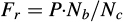 is the frequency reuse factor,
  is the bandwidth allocate to the satellite, and
  is the spectral efficiency in bit/s/Hz of the modulation and coding scheme.
By software-defined payloads, these GEO-HTS will provide flexible coverage, power, and connectivity [Reference Suber28, Reference Dios29]. Moreover, advanced modulation and coding schemes in the next-generation modems allow users to increase channel throughput, and adaptive coding enables more efficient use of higher frequency bands that are intrinsically susceptible to rain attenuation. Typical services that GEO-HTS provides are high data rate very small aperture terminal (VSAT), transmission control protocol/Internet protocol (TCP/IP) over satellite, IP-TV, HD-TV, and UHD-TV [Reference Ippolito24, Reference Minoli26].
Few providers plan to build up global networks with GEO-HTS, such as Intelsat, for applications such as maritime and aeronautical, cellular backhaul, consumer broadband, and enterprise networks. Moreover, some providers started with Ku-band transponders to develop the market, then moved to the Ka-band as demand increased [Reference Suber28, Reference Dios29]. One of the earliest broadband satellites in geostationary orbit was Thaicom 4 (IPSTAR), launched in August 2005, operating in the Ku-band and providing multibeam coverage with 84 two-way spot beams, 3 shaped broad area beams, and 7 one-way broadcast beams. Examples of other broadband, high-capacity satellites are the following, with brief descriptions of their capabilities according to [Reference Ippolito24, 30]:
▪ Ka-Sat 9A, built by Eutelsat, launched December 2010, location 9° east, lifetime 15 years, 82 Ka-band spot beams, 250 km footprint, 10 gateways, 70 Gbit/s total throughput capacity
▪ ViaSat-1, built by Space Systems Loral, launched October 2011, position 115° west, lifetime 12 years, 56 Ka-band transponders, 72 spot beams, coverage continental United States, Alaska, Hawaii, and Canada, 140 Gbit/s total throughput capacity
▪ EchoStar 17, built by Space Systems Loral, launched July 2012, position 107° west, lifetime 15 years, 60 Ka-band downlink beams
▪ lntelsat 29e Epic, built by Boeing Satellite Systems, launched January 2016, global coverage, transponders: 14 C-band, 56 Ku-band, 1 Ka-band, wide beams, area beams, 25–60 Gbit/s total throughput capacity per satellite of the Intelsat EpicNG platform
▪ lntelsat 33e Epic, built by Boeing Satellite Systems, launched August 2016, position 60° east longitude, lifetime >15 years, coverage: Europe, Africa, Asia, transponders: 20 C-band, 249 Ku-band, 1 Ka-band, wide beams, area beams
▪ ViaSat-2, built by Space Systems Loral, launched June 2017, position 69.9° west, lifetime >15 years, Ka-band transponders, coverage North and South America, 300 Gbit/s total throughput capacity, hybrid (chemical and electric) propulsion
To reduce latency, HTS can also be placed in a MEO, which can result in three to four times lower delay compared with GEO. However, in these MEO-HTS, users require steerable antennas to track the satellite and retain signal connectivity by moving from one satellite to another one within the MEO constellation [Reference Ippolito24, Reference Minoli26]. An example of an MEO-HTS system is the O3b satellite constellation, operated by O3b Networks, founded in 2007 and that is now a wholly owned subsidiary of SES S.A. It is designed for telecommunications and data backhaul from remote locations, providing high-speed connectivity to Internet service providers and phone companies. The first four satellites were launched in June 2013, and eight more in 2014. However, only nine are used operationally. There are plans to extend this to 20 satellites. The satellites were deployed in an MEO along the equator at an altitude of 8062 km (4.8 times closer to Earth, 14 dB less path loss, that is, 20 times lower power requirement than GEO), each making 4 orbits a day. Its service area can be covered continuously by a relatively small constellation compared to LEO. Each satellite is equipped with 12 fully steerable Ka-band (downlink 17.7–20.2 GHz, uplink 27.5–30 GHz) antennas (2 beams for gateways, 10 beams for remotes) that use 4.3 GHz of spectrum (2 × 216 MHz per beam) with a proposed throughput of 1.6 Gbit/s per beam (800 Mbit/s per direction), resulting in a total capacity of 16 Gbit/s per satellite. Each beam’s footprint measures 700 km in diameter. O3b claims a one-way latency of 179 ms for voice communication, and an end-to-end round-trip latency of 140 ms for data services compared to about 500 ms for GEO. The satellites weigh approximately 700 kg each [31–Reference Barnett34]. More examples and details about GEO- and MEO-HTS are given in chapter 15 in [Reference Ippolito24] and chapter 3.12 in [Reference Minoli26].
The growth in HTS has been accelerated in recent years as costs for ground terminals and satellite transponders have been coming down. Globally, the number of potential subscribers for satellite services is expected to rise quickly from about 1.5 and 3.1 million subscribers in 2010 and 2015, respectively, up to about 6 million in 2020 according to the projected growth in satellite broadband subscribers by ITU assessments. Thus, the number doubles every 5 years. This rapid anticipated growth highlights the need for continued development and launching of HTS networks, which promise a more competitive market and a key enabler to meet universal broadband targets than previous iterations of satellite technologies [Reference Martin, O’Keefe and Finucan22, Reference Ippolito24].
1.2.2 Low Earth Orbit High-Throughput Satellite Constellations
The demand for connectivity anywhere, anytime and to any device, will continue to grow in traditional sectors such as wireless connectivity and enterprise networking, but it will also open up new opportunities in providing services to the fast-growing mobility sector, that is, people/vehicles-on-the-moveFootnote 2, aiming in particular for MI (including ultra-high density and 3D video, augmented reality, virtual reality, online gaming, mobile cloud, remote computing, tactile Internet, and 3D connectivity to aircrafts and drones and smart office) and to extend IoT (including M2M and H2M) to broadly distributed entities [Reference Ippolito24, Reference Emery35]. This could include access to people’s smartphones, tablets, and laptops, as well as to various smart devices in recreational vehicles, buses, trucks, in future autonomous driving and connected automobiles, trains, boats, ships, and airplanes. Advances in smaller, less costly low-orbit satellites, capable of delivering high-speed, bidirectional services will make this possible. By positioning in low orbit rather than geostationary, low-power processors and wireless transceivers for the device back on the ground have similar technology gains [Reference Kelly36].
To ensure global coverage, mobility with low latency, high throughput, and reasonable signal power will require to deploy huge satellite constellations in LEO and/or hybrid communications solutions combining wireless terrestrial and satellite networks that work together seamlessly, since no single technology or company might reach all the possible markets and customers that will be available in the future [Reference Ippolito24, Reference Emery35]. Thus, satellite connectivity will play a critical role.
According to [Reference Fitzsimons37], nearly 4.4 billion people around the world have never been online, at least are “unconnected or underconnected” [Reference Kelby38–Reference Grossman40]. For example, in India, 80% lack access to the Internet. Even in the United States and in Europe, full coverage is not achieved, and a certain percentage of the population are lacking high-speed broadband. This is because of both economic and technological factors. For example, rural areas have much lower average revenue per user than urban ones, since it would entail significantly large backhaul infrastructure [Reference Velivela32].
This motivates new ventures to provide reliable and fast Internet to the masses via new satellite constellations. By December 2019, at least 20 systems are announced for Earth observation and at least 6 new LEO systems for telecommunications [Reference Grossman40–43]. Google, SpaceX (Space Exploration Technologies Corporation), and Boeing recently announced large investments in LEO constellations around the globe to provide Internet to rural and developing areas of the world. Google announced plans to deploy 180 small LEO satellites to provide Internet access to underserved regions of the globe. SpaceX’s proposed constellation Starlink would comprise a network of 4,425 Ka- and Ku-band small operational satellites in the category between 100 kg and 500 kg to make global Internet service a reality. Launching with SpaceX’s own rockets, the full constellation would take about 10–15 years, starting in 2019. Latency is assumed under 20–30 ms with speeds up to 1 Gbit/s through ground terminals [Reference Velivela32, Reference Kelby38, Reference Henry44]. Moreover, SpaceX proposes an even larger constellation of 7,500 V-band satellites, which would circle in an orbit below the first constellation [Reference Henry44]. Also, Boeing applied for a license of the US Federal Communications Commission (FCC) to operate between 1,396 and 2,956 satellites in LEO to provide Internet access in the V-band around the world [Reference Alleven39, Reference Werner41]. With all these satellite constellations, price per bit is aimed to approach terrestrial cellular and fiber offerings.
Because of first-mover advantage, another entity, OneWeb (founded by Greg Wyler of O3b), seems to be ahead of the schedule of all the aforementioned campaigns [45]. Among many investors are SoftBank Group, Qualcomm, Virgin Group, Hughes, Intelsat, and Airbus Group. However, in March 2020, OneWeb faced a liquidity crisis and considered bankruptcy. Then, in July/August 2020, the UK Government announced that it had acquired a 45% stake in OneWeb Global for US$500 million in a joint venture with Sunil Mittal's Bharti Global of India who would hold 55% (formerly a partner of OneWeb). It was reported that the UK would repurpose the satellites for its own Global Navigation Satellite System. It was also announced that Hughes Network Systems would invest US$50 million in the consortium [46].
The original schedule of OneWeb was to design and build 648 (+250 spare) small communication satellites in a constellation, which will offer high-speed Internet with global coverage, connecting both Internet gateways (cellular backhaul, seamlessly extend the networks of mobile operators) and end users for satellite broadband, emergency services, and mobiles, connecting people/vehicles-on-the-move. The 648 satellites in the 150 kg category will operate in circular LEOs (in 18 orbital planes of 36 satellites each) at approximately 1200 km altitude, transmitting and receiving in the Ka (20/30 GHz) and Ku (11/14 GHz) bands. Their mission life time is expected to be at least 5 years. OneWeb aims to be the first fully global, pole-to-pole HTS system with a total throughput capacity of each satellite of more than 7.5 Gbit/s and low latency less than 30 ms round trip delay and a downlink data rate to the user terminals of 50 Mbit/s, making interactive applications such as 5G mobile telephony, game playing, and web surfing possible [Reference Dios29, Reference Velivela32, Reference Henry44, 46, Reference Azzarelli47]. According to [Reference Kelly36], each satellite is designed to provide an aggregate downlink capacity of 17–23 Gbit/s. The first 74 satellites of OneWeb had already been launched in 2019. Generally, to launch a large number of satellites for LEO constellations is challenging the satellite launch services industry, since even each rocket launch might carry about 35 satellites, it requires several tens of launches [48, 49]. For example, the establishment of the aimed OneWeb constellation would have required the greatest rocket campaign in the history of spaceflight. Arianespace, OneWeb’s primary launch partner, booked already 20 Soyuz rockets to launch clusters of 32–36 satellites into orbit. But OneWeb also had contracts with Virgin Orbit for 39 launches, using its still-in development LauncherOne dedicated smallsat vehicle as well as BlueOrigin for 5 launches with a future New Glenn rocket [Reference Henry44, 45]. The high-cost structure of OneWeb's contracted launches and competition, particularly with SpaceX's self-launched Starlink constellation, might have accelerated OneWeb’s failure [46]. However, this means not the end of LEO constellations. At the moment, the race is led by Elon Musk’s Starlink, which has already launched more than 600 satellites till August 2020, but whose target is 42000 satellites. Moreover, Amazon just got approval from the Federal Communications Commission (FCC) of the United States to launch its Kuiper project with its 3326 satellites (784 at a height of 590 km, 1296 to 610 km and 1156 are located at 630 km) into space, but it is not the only one with this goal in mind [49].
1.2.3 Evolving High-Altitude Platform Stations
Beside terrestrial and satellite platforms, other high-altitude platform stations (HAPSs) are evolving due to the growing demand of broadband services, using solar-powered air balloons and space glider or drones. The ideas are not all new, but emerging technologies and innovative Internet entrepreneurs might leverage them. In the project Loon, Google aims to build up an inexpensive ground-based infrastructure with solar-powered, remote-controlled air balloons within Earth’s atmosphere to provide 3G/LTE connectivity directly to the users on the ground. These HAPSs shall be placed above 20 km height to provide a wide area below compared to the very small ones with cell towers, but with latency-like terrestrial technologies [Reference Martin, O’Keefe and Finucan22, Reference Velivela32, Reference Kelby38]. Facebook works on a small solar-powered space glider or drone called “Aquila,” with a wingspan roughly the same as that of a Boeing 737, but weighs only about 450 kg. The upper surface of the wing is covered by solar cells to power the aircraft’s four electric motors and to charge the batteries as power storage for night flights. Aquila will be able to stay at an altitude between 18 and 27 km for months at a time. It uses lasers to transmit data between planes and to terrestrial stations within 50–80 km, which can then provide Internet service locally [Reference Martin, O’Keefe and Finucan22, 50–52]. Also, Google has shown interest in high-altitude drones to deliver wireless Internet access around the world, using mm-waves, which could offer up to 40 times higher datarate than today’s 4G LTE systems [Reference Martin, O’Keefe and Finucan22, Reference Velivela32].
The advantages of using HAPSs as alternatives to satellites are their ease of deployment and ability to move easily to new locations in order to meet the demand and the changing requirements of the operator or service provider’s business plan. These concepts of HAPSs are realizable now because of the improvements in composite materials of the lightweight aircraft technology, low-power computing, battery technology, and solar panels. With respect to spectrum resources, the ITU Radio Regulations currently designated several frequency bands for HAPSs in 2 GHz, 6.5 GHz, 27–31 GHz, and 47–48 GHz ranges. As part of its agenda, WRC-19 will consider additional spectrum requirements for gateway and fixed terminal links for HAPS in the 21.4–22 GHz, 24.25–27.5 GHz, and 38–39.5 GHz bands allocated to the fixed service and could take a decision on designation of some additional bands for HAPSs [Reference Martin, O’Keefe and Finucan22].
1.2.4 Satellite Markets and Perspective
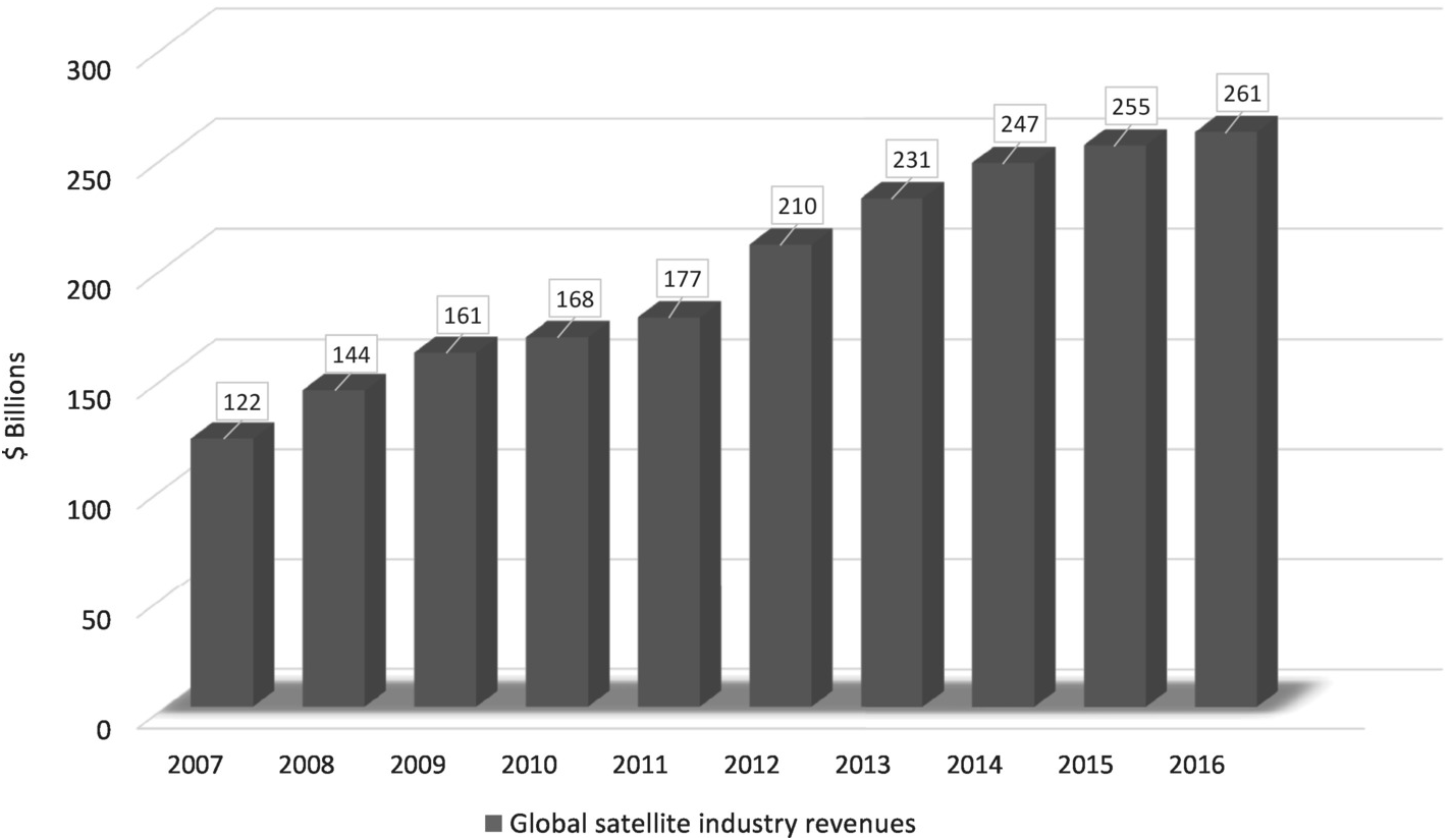
Revenues in the satellite industry are a relatively small percentage of global telecommunications revenues. In 2015, they comprised about 4% according to the Satellite Industry Association (SIA). But in terms of money, it is still a large market with an overall worldwide satellite industry revenue of $260.5 billion in 2016 with a 2% growth rate [43]. Figure 1.7 exhibits the global satellite industry revenues and growth rates from 2007 to 2016, indicating a 10-year global industry growth of two times.

Figure 1.7 Global satellite industry revenues and growth rates from 2007 to 2016 according to [43].
The satellite industry revenue in [43] is subdivided into four major segments:
▪ Satellite Services is the largest industry segment, with revenues reaching $127.7 billion, but remained flat with 0.2% growth. It includes broadcast, radio, and broadband among the consumer communication services with $104.7 billion, but also revenues from fixed satellite services with $17.4 billion, comprising transponder agreements and managed network services, mobile satellite services with $3.6 billion as well as Earth observation with $2.0 billion.
▪ Satellite Manufacturing revenues dropped down from $16.0 billion in 2015 to $13.9 billion in 2016, suffering the greatest revenue loss of 13% globally.
▪ Satellite Launch Services Industry revenues, which include revenues for all commercially competitive launches that occurred in 2016, increased by 2% to $5.5 billion after decreasing by 9% from 2014 to 2015. There were 64 worldwide commercially procured launches in 2016, subdivided in orbits: 28 GEO, 2 beyond GEO, 6 MEO, and 28 LEO.
▪ Satellite Ground Equipment includes network equipment (gateways, control stations, very small aperture terminals) and consumer equipment (satellite TV dishes, satellite radio equipment, satellite broadband dishes, satellite phones and mobile satellite terminals, and satellite navigation stand-alone hardware). The revenues rose by 7% over 2015 to reach $113.4 billion.
By the end of 2016, the total number of operational satellites was 1,459, with an increase of 47% over the preceding 5 years, where 35%, 14%, and 1% are for commercial, government, and nonprofit communications, respectively; 19% and 1% for Earth and space observation, respectively; 12% and 5% for R&D and scientific purposes, respectively; 7% for navigation; 2% for meteorology; and 6% for military surveillance [43]. Currently, there are 1,738 satellites orbiting Earth [Reference Grossman40].
The growing importance of the industry is underlined by both the continued increase in the sheer number of operational satellites in orbit and by the announced plans for new satellites with increased capabilities as well as multiple constellations with very small, lightweight satellites, having very low production costs to make them economically viable. The challenge is enormous, since satellites have never been mass produced before. A requirement to produce several small satellites a day has inspired engineers and researchers to develop innovative designs and processes that will dramatically lower the cost in large volumes for high-performance space applications [45]. These smallsats will take advantage of recent advances in consumer electronics, incorporating the latest technologies and many sophisticated functions from smartphones.
Hence, constellations of inexpensive smallsats will be a major market driver (of the manufacturing and launch markets) for the next decade. The shape of the next decade is strongly reliant on the deployment of constellations with inexpensive smallsats. For the future LEO satellite market, it is expected that more than 65% of the total 3,832 satellites will be launched between 2017 and 2025 (2,067 until 2020 and 1,765 from 2021 to 2025) will operate in constellation, experiencing a 385% growth as compared to the previous decade, where the peak of satellites per year to be launched will be around 2021 [Reference Puteaux42]. These new classes of commercial non-geostationary orbit (NGSO) systems have received a wave of investment from key players inside and outside the traditional satellite industry.
Future LEO satellite constellations aim to provide direct broadband capacity to the user all around the globe, extending terrestrial broadband connectivity and providing direct-to-customer Internet connectivity in remote areas. These emerging networks will have a global impact on humanity
▪ By delivering ubiquitous high-bandwidth communications to underserved but hard-to wire regions of the world, which contain nearly 60% of the world’s population, including remote and rural (difficult-to-reach) areas, for example to obviate the need for expensive fiber infrastructure
▪ To support maritime, aviation, and other vertical markets
▪ To enable signaling offload or creating an emergency network, for example an emergency 5G slice in the future, during times of disaster when terrestrial networks are damaged [Reference Martin, O’Keefe and Finucan22, Reference Kapovits25]
The use of electric propulsion for keeping a satellite in its operating position has already changed the global satellite industry. Although it takes months with this type of propulsion technology (because electric thrusters produce very small flow), rather than weeks with traditional chemical propulsion (which ejects large amount of propellant) to reach the final operating position or to maneuver the satellite into another slot during the satellite’s lifetime (which could be up to 25% of an operator’s fleet), economic advantages make it attractive to replace chemical propulsion by all-electric propulsion in a satellite. This approach aims to reduce the spacecraft weight, which could be only 50% of the full-chemical propellant one, and hence it could reduce the launch cost significantly, and possibly extend the spacecraft life [Reference Minoli26].
Moreover, new launch platforms such as the Falcon 9 rockets operated by SpaceX, LauncherOne by Virgin Orbit, and New Glenn rocket by BlueOrigin are approaching the market. Competition and modular design with reusable rocket technology will lower the cost of launching satellites [Reference Kelly36, Reference Henry44, 45].
1.2.5 Interoperable Satellite Networks
In the past, there had already been schemes of interoperable satellite systems in geostationary and low orbits, to combine their strengths such as low latency, low loss, small terminals, high look angle, and pole coverage for LEO as well as wide beams for global coverage (e.g., for broadcast) or spot beams for high-density areas (e.g., for broadband services) for GEO, using its fixed positions. With the emerging new LEO constellations, schemes are going ahead, using GEO and LEO interoperable networks [Reference Suber28, Reference Dios29], relying on the core wireless standard 3GPP to seamlessly integrate with future networks such as 5G phase II and 6G. According to [Reference Suber28], “Intelsat is working closely with players outside of the satellite industry such as QUALCOMM to integrate their chip technology into terminals. This will transform satellite communications from last mile solution to become an integral part of the Telecommunications network,” where the future architecture and different path to HTS are shown in some illustrations there.
1.2.6 Toward Hybrid Terrestrial 5G/6G–Satellite Networks
Besides direct broadcasting, satellite communication technology has been associated with expensive proprietary solutions, addressing primarily niche markets and applications. In the past years, satellite technology has improved both its technical performance and capabilities as well as becoming much more competitive with terrestrial solutions and infrastructure. However, in the long run, satellite networks, even LEO constellations, might not exist as stand-alone islands in the sea of connectivity. Up to now, satellites have been used in terrestrial cellular mobile networks primarily for backhaul services for long-distance and international connections only, but not to any great extent in terrestrial cellular mobile networks. However, this begins to change as fourth-generation mobile systems move into the fifth and sixth generation, where IP-based services will be widely deployed, allowing true explicit end-to-end device addressability. The integration of satellite communication promises to provide a powerful networking infrastructure. Hence, the emerging 5G and 6G visions opens up a new chapter in communications, since in the move toward 5G phase II and 6G there will be a convergence of service delivery via multiple networks and systems by aiming to merge several technologies, integrating terrestrial cellular networks alongside and in combination with satellite systems and possibly high-altitude stratospheric platforms, operating on global distribution levels. The satellite will require very high capacity links, extending the performance of current HTS systems and that might operate in expanded and new frequency allocation bands to support increasing traffic capacity [Reference Ippolito24–Reference Minoli26].
Obviously, there are some characteristic constraints of satellite communications technology compared to terrestrial solutions: (1) the low signal level; (Reference Tripathi and Khaparde2) the comparatively large propagation delay, that is, the large latency, even for LEO constellations; and (Reference Xiang, Shen and Zheng3) the relatively low capacity, even for GEO-HTS, since satellites are difficult to build and launch and power is limited even considering powerful satellites, relying on solar power or batteries.
All these factors might be improved with the new LEO-HTS systems in future. At least for long-distance communications, latencies can be better than fiber, since speed of light is around 40% higher in space than in silica glass and satellites need fewer hops with less repeaters [Reference Velivela32]. But can LEO-HTS systems bypass existing providers? Most probably not, since these new networks will be reliant on high-bandwidth interconnects. LEO constellations are undoubtedly an efficient solution for delivering service with an aggregate downlink capacity of several Gbit/s into large expanses as well as inaccessible or expensive to cable or terrestrial network areas. Here, satellite technology offers the potential for lower capital expenditure. But its downlink capacity is a fraction of modern domestic fiber interconnects higher than 100 Gbit/s.
In opposite, there are also some features and capabilities of satellite communication that distinguish it from terrestrial solutions: (1) the capability to address large geographic regions, even continents, using a minimum amount of infrastructure on the ground; (2) its flexibility; and (3) its intrinsic broadcast capability, which enables satellite communication to deliver the same content to a very large number of network nodes and user devices with unparalleled efficiency. Because of these capabilities of satellites, it should be considered as complementary, rather than a replacement for fixed or terrestrial mobile infrastructure, extending coverage into areas where it is not cost effective to do so terrestrially or supporting terrestrial solutions in delivering on the 5G and 6G promises, some of which are very challenging [Reference Kapovits25, Reference Velivela32, Reference Kelly36].
1.3 Technologies
As described in the previous Sections, mobile traffic will increase dramatically in the next years and decade. The proliferation of smartphones, tablets, laptops, and other portable devices is placing greater demand for new services, increasing the capacity or data rates significantly. This requires improved spectrum efficiency methods as well as higher frequencies with larger bandwidth, which is aimed for in the future 5G mm-wave systems as well as geostationary and particularly non-geostationary satellite and high-altitude platforms. With different frequency allocations for different services, mobile devices are required to operate in multiple bands simultaneously. One approach is to use frequency-agile components in the RF front end such as frequency-agile multiband antennas, tunable filters and adaptive matching networks, for example integrated into wideband high-power amplifiers. This would reduce parallel trunks, and hence space, since many portable devices have constraints on the dimensions. Another key component, particularly for on-the-move applications, is the “smart antenna,” creating dynamically a desired antenna pattern toward the target of interest, for example a satellite, by constantly tracking the antenna beam toward it, during driving or flying. Figure 1.8 exhibits a scenario of various applications and platforms with some important characteristics, which will be discussed in the text that follows, following to some extent the software-defined radio (SDR) approach.

Figure 1.8 Scenario of various applications and platforms with some important characteristics, including beam-steering antennas and agile components, following the software-controlled radio approach.
An SDR is a radio in which some or all physical layer functions are software defined, where the term physical layer is defined by the Open Systems Interconnection (OSI) model. The broad implication of the term software defined is that different waveforms can be supported by modifying the software or firmware but not changing the hardware, where the term waveform refers to a signal with specific values for all the parameters such as carrier frequency, bandwidth or data rate, modulation, coding, and so forth [Reference Grayver53]. According to the strictest interpretation of this definition, most radios are not software defined but rather software controlled. While a software-controlled radio is limited to functionality explicitly included by the designers, an SDR may be reprogrammed for functionality that was never anticipated. In the ideal SDR, the user data are mapped to the desired waveform in the microprocessor. The digital samples are then converted directly into an RF signal and sent to the antenna.
The ideal SDR hardware should support any waveform at any carrier frequency and any bandwidth. Assuming a 60 GHz RF signal, without an RF front end to select the band of interest the entire band must be digitized. According to Nyquist’s criterion, the signal must be sampled twice at the maximum frequency, that is, 2 × 60 GHz = 120 GHz. Capabilities of currently available A/D converters are nowhere close to 120 × 109 samples per second. Furthermore, interfering signals can be much stronger than the wanted signal, for example having a large power difference of 120 dB. The digitizer must have sufficient dynamic range to process both the strong and the weak signals. An ideal digitizer provides about 6 dB of dynamic range per bit of resolution. Thus, the digitizer would then have to provide well over 20 bits of resolution. However, an A/D converter with these specifications violates the Heisenberg uncertainty principle and is therefore not realizable. The maximum A/D precision at 120 × 109 samples per second is limited to 14 bits [Reference Walden54]. Thus, this is beyond the capabilities of modern processors and is likely to remain so in the foreseeable future. Moreover, the digitizer must be very linear. Nonlinearity causes intermodulation between all the signals in the digitized band. Even a high-order intermodulation component of a strong signal can swamp a much weaker signal. Furthermore, physical size and power consumption are other issues, in particular for handheld devices. Hence, an ideal SDR may be perfect for a research laboratory, but not suitable for a given application, considering these technical problems [Reference Grayver53].
In contrast, a software-controlled radio (SCR) has an RF front end, which should be reconfigurable or frequency-agile, controlled by software in order to tune carrier frequency and/or the bandwidth of the waveform dynamically, at least over a wide frequency range, including several frequency bands. Some of the SDR functionalities are then implemented smartly into the RF front end, which could save physical size and power consumption and overcome the technical problems of an ideal SDR. Of course, at a first sight, an SCR, similar to an ideal SDR, faces the problem of higher complexity and higher cost compared to conventional radios, because the frequency-agile components of the front end are more complex and costly than fixed ones. But when several parallel trunks for different frequency bands can be reduced with frequency-agile technologies, it might be the opposite. Moreover, it reduces chip area and complex power management and it provides higher energy efficiency through adaptive matching. However, it needs control for the adaption and baseband processing. An example is illustrated in Figure 1.9.

Figure 1.9 Example of a frequency-agile transceiver with baseband (software) reconfiguration for multistandard operation and a reconfigurable RF front end with some reconfigurable/tunable analog RF components for multiband operation and beam-steering.
Independent of the specific approach, SDR or SCR both address the following characteristics of a communication system, which are briefly summarized below [Reference Grayver53]:
▪ Interoperability to seamlessly communicate with multiple incompatible radios or act as a bridge between them.
▪ Spectrum efficiency, that is, efficient use of resources under varying conditions to adapt the waveform for maximizing the key metric. For example, a low-power waveform can be selected if the radio is running low on battery or a high-throughput waveform can be selected to quickly download a file. Delay can be related to throughput. By choosing the appropriate waveform for every scenario, the radios can provide a better user experience.
▪ Opportunistic frequency reuse (cognitive radio) to take advantage of an underutilized spectrum. If the owner of the spectrum is not using it, an SDR/SCR can “borrow” the spectrum until the owner comes back. This technique has the potential to dramatically increase the amount of available spectrum. This requires “intelligent” spectrum sensing capabilities.
▪ Power efficiency, that is, a tradeoff of bandwidth or data rate and power, which are key constraints in a wireless system.
▪ Upgrading to support the latest communications standards. This capability is especially important for radios with long life cycles. Thus, a new standard or new allocated frequency band can be rolled out by remotely loading new software into a base station or user terminal, saving the cost of new hardware and the installation labor.
▪ Lower cost by adapted its use in multiple markets and for multiple applications, for example for 5G and satellite communication systems or in hand-held devices as well as in automobiles.
The last two features affect the deployment efficiency, that is the network throughput per unit deployment cost, consisting of both the hardware and operational expenses.
The lack of tunable RF bandpass filters, in particular with a high quality factor (Q-factor) and at mm-wave frequencies, is one of the largest impediments to realize a SCR. Of course, filters can be tuned mechanically, resulting in limited practical use. Selecting one filter from a bank of available filters is a technique often used currently. However, this takes up a great deal of space, might cause some additional losses, depending on the switching level and might pass some interference via the “off” switches, since switches are not ideal. Moreover, in both cases, bandwidth cannot be adjusted. Another issue is adaptive matching, for example of the antenna or even more challenging, of the high-power amplifier in the transmitter stage.
A key component of all wireless systems is the antenna, where four characteristics are of specific interest: (1) its input impedance, which should be matched to the following RF circuit; (2) its frequency response, since an antenna inherently acts as a filter; (3) its space response by designing its pattern, which can be used as a space filter; and (4) its polarization, which can be used to increase the capacity.
In many applications, particularly in the SDR/SCR approach, it would be a significant advantage to dynamically change/tune these characteristics of an antenna electronically (instead mechanically) to enable adaptive matching, polarization-agility, frequency-agility, and beam-forming or beam-steering (space-agility). That could mean in the case of a frequency-agile antenna, instead of using a wideband antenna with low performance over the entire frequency range of interest with different frequency bands, for example for different services, we could use a tunable narrowband-antenna with good performance, and then tune it over the entire frequency range, thus selecting the individual band of interest. A tunable narrowband antenna typically provides higher gain than a similar sized wideband antenna, or vice versa saves space for similar gain. At the same time, these frequency-agile multiband antennas could be adaptively matched to optimize dynamically any detuning due to proximity effects or a changing environment, for example of handsets [Reference Petosa55, Reference Zheng56]. This kind of antenna can provide an inexpensive solution and might better meet the constraints on the form factor, particularly size and shape, of handsets and portable devices.
In the approach of the next generation of terrestrial mobile and satellite systems, including 5G mm-wave and 6G systems, and constellations in all orbits (GEO, MEO, and LEO) as well as future high-altitude platforms, higher frequency bands, in particular Ka-band, V-band, and W-band, are exploited in order to provide high bandwidth and hence higher data rates. To compensate some of the huge path losses (mainly free-space propagation losses) in the power link budget at these high frequencies, large (in terms of wavelength), highly directive, high-gain antenna configurations are required to focus the narrow beam toward the desired hub (satellite, access point, relay, or base station). Conventionally this can be done with a static beam formed by a simple parabolic dish, or more complex, by double-reflector configurations such as Cassegrain or Gregorian antennas. However, when the hub, for example an LEO satellite, and/or the customer or user terminal, for example in an automobile, are moving, then these antennas must be mechanically steered to maintain the direction of the static beam accurately toward the target of interest. This requires a gyroscopic-controlled mechanical system that moves the whole antenna to scan the desired space. These antenna systems with mechanical motorized gimbals for steering are large, heavy, and bulky, and hence lack aerodynamic qualities. They consume a great deal of power for steering, are expensive, and can require additional high maintenance. This is usually also the case for hybrid electronic-mechanical steered antennas, making both impractical to deploy for large-scale applications.
Therefore, smart antennas with dynamic beam-forming capabilities are aimed for the aforementioned platforms, creating dynamically a desired antenna pattern. An example might be a mobile (RV, bus, truck, self-driving cars, train, boat, ship, or airplane), where its antenna constantly tracks the desired hub during moving by positioning the antenna’s main beam continuously toward the hub, and at the same time might put pattern nulls in directions of strong interferers.
The smart antenna concept covers a wide range of techniques with different complexity and performance/capabilities (degree of parameters to be changed), including multiple input–multiple output (MIMO), beam-forming and beam-steering techniques. Beam-forming is a technique that combines appropriately scaled and delayed signals of individual antenna elements to create the desired shape of the beam. While MIMO is fully implemented in the digital domain, beam-forming and beam-steering could be realized in the analog RF or IF band, in the digital baseband, or even in a hybrid analog/digital implementation, depending on the system requirements and cost. The various working principles and schemes as well as advantages and disadvantages of its hardware and software implementations are given in Section 2.2.
One focus of the book at hand is on beam-forming and beam-steering techniques. While beam-forming requires electronically controlled amplitude tapering and phase shifting across the individual antenna elements, beam-steering needs only electronically controlled phase-shifting to track the desired hub by positioning the narrow beam constantly toward it. Because of the lower complexity of beam-steering, it is potentially more cost effective and less power consuming, in particular for large arrays with a great number of antenna elements, for example 64 × 64, but of course, enables less performance than beam-forming and MIMO. However, in many applications, it would be already a breakthrough to enable cost-efficient electronically steerable antennas (ESAs), in particular for mm-wave systems, where complexity, technological constraints, and cost increase, and where implementing ESAs is still very challenging because of the conflict in finding robust, reliable, low-cost hardware solutions in particular for large antennas and wide-scale applications that match, at the same time, the most important system’s requirements or at least provide antenna performance sufficient for the desired applications.
There are different ESA concepts that had been investigated worldwide such as transmit arrays, reflectarrays, digital active and analog passive, as well as metamaterial-based phased arrays, using different technological approaches to steer the beam. Phased arrays are most common, where the first phased array transmission was originally shown in 1905 by Nobel laureate Karl Ferdinand Braun, who demonstrated enhanced transmission of radio waves in one direction. It creates beam-steering from a large array of small antenna elements for high gain, which are most often printed microstrip patches with a half wavelength squared dimension. By electronically changing the relative phase of up to 360° for the signal that each antenna element transmits, the combination of all of these small signals creates a larger focused beam in a particular direction, which can be directed instantaneously in any direction by fully electronic control, and hence track the movement, for example of any satellite, no matter how or where you move, without the need for any mechanical moving parts.
The challenge is to miniaturize the phase shifter and to improve the performance, while reducing the manufacturing cost to an economical price point, in particular for large arrays. Phase shifters (see Section 2.2) can be realized in different technologies: in semiconductor technologies, in particular silicon technologies (complementary metal–oxide-semiconductor, CMOS and bipolar CMOS, BiCMOS) that offer much lower cost as compared to InP or GaAs technologies, and can address consumer applications, with RF microelectromechanical systems (RF-MEMS), and by using functional materials such as ferrites, ferroelectrics (in particular barium strontium titanate [BST]) and microwave liquid crystals (MLCs). Advantages and drawbacks of the different technologies for higher frequency bands are given in Section 2.4.
Concerning system’s requirements, appropriate response times had already been mentioned in Section 1.2, in the context of different categories of applications – portable, slow-moving, and on-the-move – where for the last one, they must be at least in the range of few tens of milliseconds. Other important characteristics of ESAs are the scanning range and insertion loss; for example, in cases in which analog phase shifters are being implemented, the phase shift should be 360°, accompanied with low losses. This is expressed in the phase shifter figure-of-merit (FoM) in [°/dB]. Moreover, in the transmit mode, high power handling is a key figure for many systems, where antennas must manage tens up to hundreds of watts, for example in satellites, with limited power supply. Hence, insertion loss and power consumption to steer these antennas must be as low as possible to avoid massive power losses and power dissipation in the antenna and to operate the ESA terminals, particularly for vehicles, ships, mobile terminals, and autarkic M2M systems, with battery, renewable energy, and off-grid power solutions. Moreover, ESAs have to be manufactured to withstand the vibration and thermal environment on the aircrafts, vehicles, trains, ships, and so forth. Hence, a robust and reliable technology has to be used for manufacturing, where the key figure will be the cost per terminal to enable wide-scale applications.
Currently, there are different approaches by some spin-off companies for developing, producing, and commercializing cost-efficient large-scale ESAs for satellite systems, but most probably also for future 5G mm-wave systems. All of them aim for low-profile and light ESAs with a modular concept to be scaled to any requirement and a thickness of few centimeters only (maximum 10 cm at Ku-band). Moreover, all work on the form factor of their ESAs, for compact stand-alone terminals with aesthetic appearance and to integrate them smartly or nearly seamlessly into the structure or body of a carrier object such as into the skin of an airplane, or into the rooftop of a vehicle or the cover of a notebook-like terminal. Four spin-off companies will be briefly introduced (status Dec. 2019).
Phasor (www.phasorsolutions.com) builds up a modular, digital phased array antenna based on patented innovations in the architecture and design of custom RF & Digital Application Specific Integrated Circuits (ASICs or microchips). Digital beam-steering is done by using a large number of ASICs, each directly connected to the small patch antenna elements of the array. The embedded microprocessors are able to dynamically control the signal phases of each element to combine and steer the beams in any direction. This active array consists of a number of smaller repeated modules. Each module fits onto two printed circuit boards (PCBs). The upper PCB hosts the array of patch antenna elements on the front and the ASIC microchip on the back. A second back-board provides the power, control, and communications for the system. All this stacks up to be less than about 2.5 cm thick. These modules can be combined to create a larger antenna to meet the required performance. Moreover, modules can also conform and be shaped to any curved surface, for example to host the ESA in the fuselage of an aircraft or in the superstructure of a yacht. Because of the active circuitry, price per terminal and power consumption will still be quite high, particularly for arrays with a large number of antenna elements, for example 64 × 64, to achieve high gain.
Isotropic Systems (www.isotropicsystems.com) uses a passive “optical” beamformer (specifically designed lens) to control and concentrate radio waves with a high degree of accuracy onto a number of active feeds and associated circuitry. With this hybrid approach, Isotropic Systems claims to “reduce the required circuitry of conventional active phased arrays and flat panels by 70–95%” with corresponding results of lower cost and lower DC power consumption. Moreover, because its solution implements true time delay, it provides significantly more bandwidth. The scanning range of their terminal is driven by the number of feeds within each module, which can be optimized to match the scanning requirements of a specific application. The number, arrangement, and orientation of modules set the gain of the terminal, which is more than 10 cm thick for the Ku-band. Each module can be tilted and conformed to fit any curved surface. This modular concept allows combined Tx/Rx in the same aperture but offers the option to have separate Tx/Rx lenses, or lenses with combined Tx/Rx in the same lens.
Kymeta Corporation (www.kymetacorp.com) provides a flat-panel passive ESA by using metamaterial structures to form “holographic” beams that could link to satellites while the antenna is in motion. Kymeta’s Metamaterials Surface Antenna Technology (MSA-T) is going back to the fundamental research on metamaterials of Prof. Smith and his team at Duke University [Reference Smith, Padilla, Vier, Nemat-Nasser and Schultz57, Reference Shelby, Smith and Schultz58]: and Dr. Kundtz’s pioneering use of metamaterials technologies in electronic beam-forming applications, which ultimately led to the spin-out of Kymeta Corporation in August 2012. The principle is described in one of his patents [Reference Bily, Boardman, Hannigan, Hunt, Kundtz, Nash, Stevenson and Sullivan59]: “scattering elements are made adjustable by disposing an electrically adjustable material, such as a liquid crystal, in proximity to the scattering elements. Methods and systems provide control and adjustment of surface scattering antennas for various applications.” The entire passive array could then build up by a stack flat panels, reducing the complexity of the N × N phase shifter, biasing and feeding network of a conventional passive phased array, ultimately reducing the manufacturing costs for the same technology. Moreover, owing to the MLC used, there is potential for another dramatic cost reduction and for a lower power consumption compared to semiconductor based phased arrays. Kymeta flat-panel antenna can steer the beam and to control its polarization. However, metamaterial structures have inherently frequency-selective characteristics, limiting the antenna’s operating bandwidth.
ALCAN Systems (www.alcansystems.com) is a German-based smart antenna technology start-up developing LC-based phased array antennas. It is a multilayer approach on different stacks, which is similar to Phasor’s, with a specially designed MLC layer inside a conventional passive phased-array antenna structure with a number of radiating elements, and at the back side, a semiconductor integrated circuit to control LC-based phase shifters. This MLC technology has been researched and developed by Prof. Jakoby’s group at Technische Universität Darmstadt in close cooperation with the research department of the Performance Materials Division of Merck KGaA, Darmstadt since 2002. The viability of broadband MLC-based phased array antennas was proved by Dr. Karabey in 2012 and published in [Reference Karabey60, Reference Karabey, Gaebler, Strunck and Jakoby61]. One of those early prototypes is shown in Figure 1.10. Following the modular concept, one module consists of 8 × 8 microstrip patch antenna elements. Then, several modules build up the ESA with an appropriate size to meet the application’s specific requirements. By using the loaded-line concept with periodic tunable LC varactors of about 4 µm thickness [Reference Goelden, Gaebler, Mueller, Lapanik, Haase and Jakoby62–Reference Jakoby, Gäbler and Weickhmann64], the response time is less than 30 ms. Moreover, polarization degradations can be compensated by using LC polarization-agile schemes [Reference Karabey60, Reference Karabey, Bildik, Bausch, Strunck, Gaebler and Jakoby65].

Figure 1.10 A photo of one of the first LC-based phased array antenna fabricated in an LC TV production line (2012, courtesy of ALCAN Systems GmbH). The photo shows the backside of the 1.5 mm thick antenna with fully integrated 8 × 8 spiraled microstrip delay line phase shifters, feeding network, and thin bias lines (not visible).
In conclusion of this section, Figure 1.11 summarizes all the aforementioned RF smart system functionalities in the upper line below the schematic pictures and some examples of tunable components below as well as some materials and technologies to implement them, where both are described in more detail in Chapter 2.
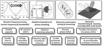
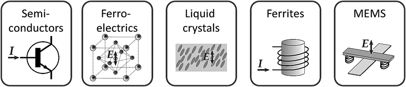
Figure 1.11 Schematic pictures of RF smart system functionalities and some examples of reconfigurable and tunable components as well as some related materials and technologies for hardware implementation.
Beyond the reconfigurable circuits and technologies, there are other fixed (not reconfigurable or smart) key components for mm-wave systems such as power amplifier, low-noise amplifier, mixer, and analog-to-digital and digital-to-analog converter. These devices are described in many books in the recent literature, and therefore will not be discussed in this book.
In this book, three technologies that are suitable for the design of mm-wave tunable/reconfigurable components, circuits, and devices are described, namely silicon technology (CMOS and BiCMOS) in Chapter 3, RF-MEMS in Chapter 4, and MLC technology in Chapter 5. In Chapter 2, basic concepts of tunable components and circuits are presented, to introduce the components and circuits described in the next three chapters.