


1. Introduction
The additive manufacturing (AM) process, laser powder bed fusion (LPBF), builds parts layer by layer using a laser beam to melt metal powder. This process has enabled the production of high-performance, end-use space industry products with properties comparable to those made through traditional manufacturing methods (Reference Sacco and MoonSacco & Moon, 2019). With LPBF, space component designers can readily use part consolidation methods to reduce weight, improve performance, and lower costs by combining multiple parts into one component (Reference Borgue, Panarotto and IsakssonBorgue et al., 2019). For example, satellite manufacturer Optisys LLC achieved a 95% weight reduction and a 20-25% reduction in production costs for a metal micro-antenna product demonstrator by consolidating the component from 100 parts to 1 (Reference OvertonOverton, 2017). While LPBF allows for greater design complexity than traditional subtractive processes, its layer-by-layer building process on powder introduces design constraints and challenges that require new design knowledge, support, and methods to overcome.
The building of support structures is often used to address LPBF’s buildability limitations in complex component designs such as rocket engine turbopump impellers (Reference Zink, Bourdon, Junior, Sias, Kitsche and WagnerZink et al., 2020). However, support adds costs and requires design adaptions for removal, which can impact product functionality (Reference Zink, Bourdon, Junior, Sias, Kitsche and WagnerZink et al., 2020). Hence, minimal support use is preferred. However, unsupported areas overhang the powder bed beneath when built. As a result, the melt pool seeps into the semi-sintered powder, leading to rough surfaces and dimensional inaccuracy once cooled (Reference Charles, Elkaseer, Paggi, Thijs, Hagenmeyer and ScholzCharles et al., 2021). In design guides for LPBF, 45 degrees is often stated as the maximum unsupported slope angle to maintain buildability and surface quality (Reference Diegel, Nordin and MotteKokkonen et al., 2016; Reference Kokkonen, Salonen, Virta, Hemming, Laukkanen and SavolainenDiegel et al., 2019). The higher the inclination angle of a section, i.e., the more it overhangs on the powder, the higher the surface roughness and the greater the difficulty in producing the part (Reference Kokkonen, Salonen, Virta, Hemming, Laukkanen and SavolainenKokkonen et al., 2016).
Surface roughness in as-built AM parts acts as crack initiation sites by increasing stress concentrations (Reference Pegues, Roach, Williamson and ShamsaeiPegues et al., 2018). Further, at unsupported overhangs, the absence of solid material beneath alters the laser heat transmission, leading to overheating and different heat transfer behaviour (Reference Ullah, Akmal, Laakso and NiemiPaudel & Thompson, 2019; Reference Paudel and ThompsonUllah et al., 2020). Hence, the material properties in these regions, such as fatigue strength, can differ from the rest of the part (Reference Kahlin, Ansell, Basu, Kerwin, Newton, Smith and MoverareKahlin et al., 2020). Post-processing is a commonly improving surface and material properties. However, Kahlin et al. (Reference Kahlin, Ansell, Basu, Kerwin, Newton, Smith and Moverare2020) assessed various techniques and found significant variation in their effectiveness. While centrifugal finishing and shot peening improved fatigue properties, laser polishing had a detrimental effect. They also concluded that fatigue performance is influenced by residual stresses, microstructure, and subsurface defects, not just surface roughness. Although methods to quantify and correlate surface roughness with fatigue performance are being developed (Reference Wycisk, Solbach, Siddique, Herzog, Walther and Emmelmanndu Plessis & Beretta, 2020; Reference Plessis and BerettaWycisk et al., 2014), they are in their infancy. To address surface roughness design challenges, developing Design for AM (DfAM) knowledge and support is vital for enabling designers to fully exploit LPBF’s capabilities while balancing part performance, buildability, and post-processing costs. However, as Kranz et al. (2015) highlighted, a lack of adequate design support has limited LPBF’s adoption.
DfAM approaches have been developed to address surface roughness challenges. For example, Charles et al. (Reference Charles, Elkaseer, Paggi, Thijs, Hagenmeyer and Scholz2021) established equations to predict and model surface roughness on down-skin surfaces and its effect on dimensional error. Computer-aided design (CAD) and engineering (CAE) supports are also emerging. For example, Ahn et al. (Reference Ahn, Kim and Lee2007) created a genetic algorithm to optimise part build orientation for minimal post-processing. These supports help designers reduce uncertainty regarding surface roughness’s impact on dimensional accuracy and post-processing. However, they provide no information on its influence on material properties or provide guidance if post-processing is unfeasible. Overall, existing software is not yet well adapted for accurately modelling surface roughness, its effect on material properties, or the geometry of as-printed AM parts (Chahid et al.,Reference Chahid, Racasan, Pagani, Townsend, Liu, Bills and Blunt2021).
Parametric studies are often conducted to acquire surface roughness and product performance data to inform design choices (Reference Zhou, Zhu, Liu, He, Zhang and YangZhou et al., 2021). While useful, such studies can require considerable time and resources, making them impractical for early design phases. Instead, Dordlofva and Törlind (Reference Dordlofva and rlind2020) emphasise the importance of product-specific test artefacts for evaluating part and process-related uncertainties. They propose a design process that uses part representative AM test artefacts to explore product-specific uncertainties related to design, manufacturing, material properties and post-processes. These AM design artefacts (AMDAs) help develop design understanding without requiring full part production, extensive parametric studies, or reliance on insufficient software support.
Despite ongoing efforts to develop design support for metal AM (Reference Wiberg, Persson and lvanderWiberg et al., 2019), Obilanade et al. (Reference Obilanade, Dordlofva and rlind2021) identified a gap in effective design support for addressing LPBF surface roughness challenges. This gap limits designers’ ability to manage surface roughness effects on part performance and buildability. Hence, the purpose of this paper is first to explore the current state of DfAM support for LPBF surface roughness through an updated state-of-the-art literature review. It then presents a case study investigating the impact of design-related surface roughness on material properties using AMDAs. The case study demonstrates AMDAs’ effectiveness in mitigating design uncertainties. The paper concludes with a discussion on industry implications, the role of AMDAs in design decision-making, and recommendations for future research.
2. Surface roughness DfAM state-of-the-art
To understand the availability of support for designers addressing surface roughness in LPBF part design, a literature review on AM surface roughness design support was conducted over four years. The literature review builds on the work of Obilanade et al. (Reference Obilanade, Dordlofva and rlind2021, Reference Obilanade and Dordlofva2022), using the same PRISMA method and search terms to review and categorise articles on LPBF, surface roughness, and design. This study aimed to continue to track trends in roughness design literature and identify the latest in AM surface roughness design support, identifying articles that focus strictly on studying product design for AM and surface roughness consideration through design methods, guidelines, tools or processes. This review is the third iteration of the study; the first was conducted in October 2020, the second in October 2021 and the third in September 2024. Figure 1 compares the categorisation of surface roughness literature published over the four years. The previous results, detailed review method, category definitions, and summary of initial findings from the earlier studies are available in Obilanade et al. (Reference Obilanade, Dordlofva and rlind2021, Reference Obilanade and Dordlofva2022).
Chart of paper categorisation comparing the number of relevant papers found during 2020, 2021 and 2024 reviews [total # papers]

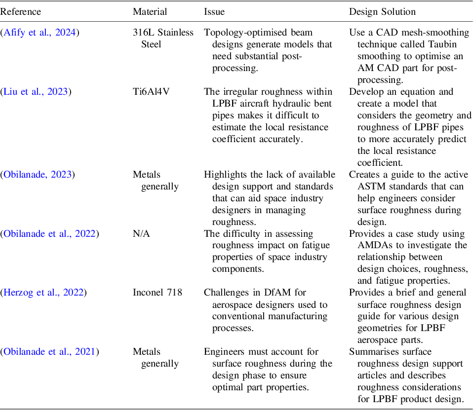
The 2024 review identified 1561 articles, with 1076 articles deemed relevant to the study, representing an increase of 639 relevant articles since the 2021 study. Six of these new relevant articles were categorised as an LPBF surface roughness design article, summarised in Table 1, a 111% increase since the previous review in 2021, which had identified five new design-related papers. The researcher authored three of the six new articles; two were directly relevant to the present study. The remaining three focus on general guidance for surface roughness design, a CAD software solution, and a specific design-roughness-performance issue.
Summary of newly categorised surface roughness design papers

All relevant articles were published after 2010. The review found that while design article publications have declined, build parameter studies on surface roughness remain the most prominent category. Additionally, articles on LPBF applications for specific components, emphasising surface roughness considerations, have notably increased from 19 to 91. The decline in the rate of design-focused article publication contrasts with the 2021 review, which noted an increased rate. Design articles account for 1% of the relevant articles identified in 2024, returning to the level observed in 2020, indicating limited surface roughness design support for LPBF designers. However, interest in understanding LPBF surface roughness continues to grow, as shown by the yearly increase in relevant articles.
3. Research method
This paper builds on previous research on the use of AMDAs by space industry engineers presented by Dordlofva & Törlind (Reference Dordlofva and rlind2020) and Obilanade et al. (Reference Obilanade and Dordlofva2022, Reference Obilanade and Dordlofva2024). Further, AMDAs have been evaluated for their characteristics as a design support, with a detailed AMDA method outlined in Obilanade et al. (Reference Obilanade and Dordlofva2024). These previous works present the industrial case study related to the artefact design of this paper. Engineers in these works used AMDAs as an alternative testing method to examine the relationship between design, surface roughness, and material properties, focusing on a 4 mm unsupported roof radius design feature identified from a consolidated LPBF rocket engine turbine manifold. Since the manifold design was already established and the AMDAs did not influence the final product design, artefacts provided additional insights into surface roughness effects on fatigue life and alternative verification and validation methods.
An initial artefact, ‘artefact A’, was designed by Dordlofva & Törlind (Reference Dordlofva and rlind2020) to investigate internal surface roughness and its impact on fatigue properties by comparing an unsupported 4 mm roof radius (R1) with a horizontal 4 mm reference radius (R2). They printed and fatigue-tested a set of artefacts, which provided design insights. However, the artefacts suffered from poor geometric accuracy due to excessive surface roughness and failed off the R2 axis, revealing AM process characteristics that were unaccounted for in the artefact design.
Thus, ‘Artefact B’ was developed by Obilanade et al. (Reference Obilanade and Dordlofva2022), incorporating the newly gained process knowledge. The design was modified with a square geometry to prevent off-radius failure by ensuring the weakest point was at the radius. Additionally, the artefact was tilted to improve roof geometry by reducing thermal stress effects during cooling. These changes enabled a more representative investigation of the design-roughness-properties relationship using two variations: an as-built condition (B1) and a machined surface version (B2) with identical dimensions. This approach enhances understanding surface roughness effects by comparing the best-case scenario (machined) with the likely scenario (as-built). The design and geometries of both artefacts are presented in Figure 2. This paper presents the findings regarding the design-roughness-properties relationship of the 4 mm radius from examining artefact B. The results contribute to understanding how design artefacts can effectively aid engineers in investigating design uncertainties during product development.
Design artefact geometries for artefacts A, B1 (as built) and B2 (machined) (all internal angles 90° and dimensions in mm)

3.1. Manufacturing and artefact preparation
All Artefacts were manufactured in Inconel 718 using an EOS M290. Artefacts were heat treated according to AMS 2774, stress relief was performed at 1065C for two hours, and ageing was performed using parameters in AMS 2774. All artefacts were removed from the baseplate using Electrical Discharge Machining (EDM) and prepared for radius fatigue testing as described in Obilanade et al. (Reference Obilanade and Dordlofva2024).
3.2. Fatigue testing
Fatigue testing was conducted with a load stress ratio (Fmin/Fmax) of 0.1. The test method employed was load control fatigue. Testing was performed at room temperature in an air environment, using a sinusoidal waveform at 10 Hz. Given the limited number of artefacts and three testing conditions (as-built radii R1/R2 and as-built or machined R2 surface), a fixed loading range (same Fmin and Fmax) was applied to simplify lifetime comparisons (cycles to failure). The load range for the run-out was specified to achieve failure within 500 to 50,000 cycles, ideally, between 5,000 and 50,000 cycles, as lower loads increase the influence of surface roughness (Reference Plessis and Berettadu Plessis & Beretta, 2020). Based on a finite element analysis of artefact B, an initial maximum load (Fmax) of 5 kN was proposed, confirmed by quasi-static bending tests. The quasi-static and fatigue tests were conducted on an Instron 1272 servo-hydraulic loading machine.
3.3. Evaluation and analysis
In AM research, the most common parameter of surface roughness measurement is the Ra value, which is the arithmetical mean of the absolute values of a roughness sampling length (Reference Gadelmawla, Koura, Maksoud, Elewa and SolimanGadelmawla et al., 2002). Additionally, the mean roughness value of the sampling length within an evaluated area (Rz) is commonly recorded as it is more sensitive to peak variations (Reference Gadelmawla, Koura, Maksoud, Elewa and SolimanGadelmawla et al., 2002). The surface roughness was measured using a contact stylus profilometry tool (Mitutoyo SJ-410 Surface Roughness Tester). Ra and Rz measurements were performed at R1 and R2 of the B1 artefacts. The artefacts were carefully pulled to fracture to evaluate the fracture surface appearance. The surface condition of the inner surface, including R1 and R2, in as-built and machined condition, was initially examined using a stereomicroscope (Nikon SMZ1270). Subsequently, the artefacts were immersed in acetone and cleaned using ultrasonic cleaning before being evaluated with a scanning electron microscope (JEOL IT300). The fractography was carried out at various magnifications with the main aim of evaluating the initiation sites of the fatigue cracks. Afterwards, selected specimens were cut, ground and polished by conventional methods for microstructural characterisation. The microstructure was revealed through electrolytic etching at 3V using diluted oxalic acid (10g oxalic acid, 100 ml H2O). A light optical microscope was used to study the microstructural characterisation of the area from R2 along the edge to R1 (Nikon Eclipse MA200).
4. Results
4.1. Surface roughness
Ten B1 and ten B2 artefacts were printed, and the Ra and Rz values of the two B1 artefact radii were measured. An image of the radius surface condition post-testing is shown in Figure 3, and the roughness values are shown in Table 2. The radii measurement results show that the severity of surface roughness was greater at R1 than at R2, as expected. Further, the average Ra and Rz values at R1 were 4.5 times and 3.7 times larger than the R2 values, respectively.
Post-testing surface images of R1 radius machined (top) and as-built (bottom)

Surface roughness measurements (Ra and Rz) for ten B1 artefacts: R1 and R2 radii

4.2. Geometric accuracy
The R1 and R2 radii of the ten B1 artefacts were measured to compare with the design and are presented in Table 3. The average geometric deviation from the 4 mm radius design was −0.31 mm and −0.1 mm for R1 and R2. An average deviation of roughly 8% and 2.5% was calculated. Compared to the values obtained for the A-artefact available in Obilanade et al. (Reference Obilanade and Dordlofva2022), this is an average deviation improvement of 21.75% for R1. These values indicated that the design changes between the artefact iterations had produced a design artefact more representative of the 4 mm radius feature.
As-built B artefact radius measurement values

4.3. Fatigue testing
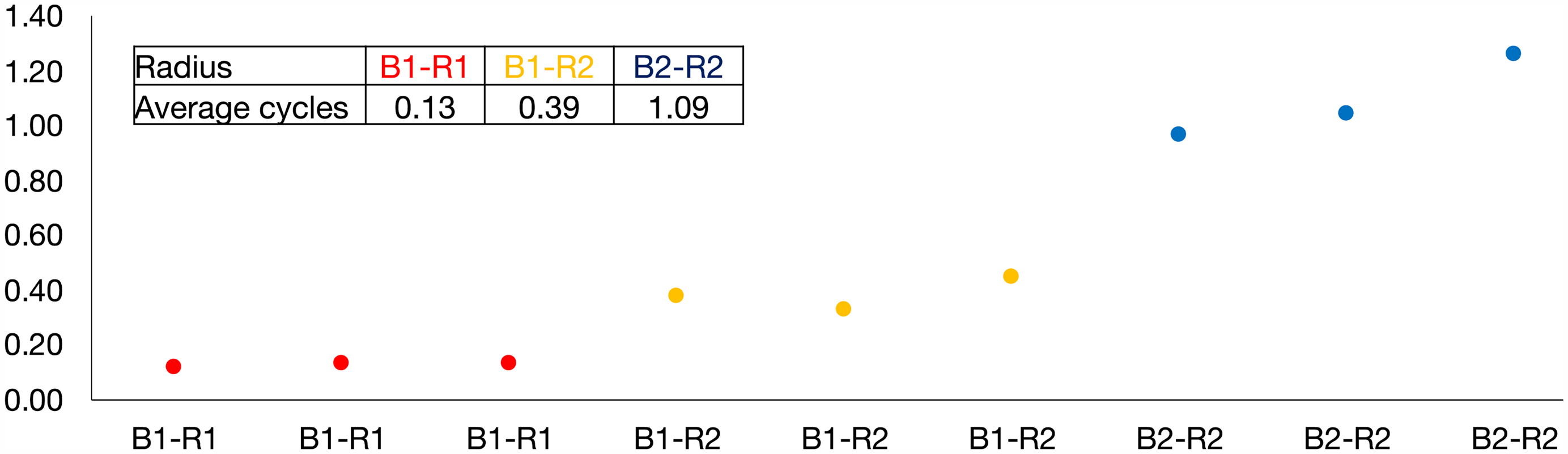
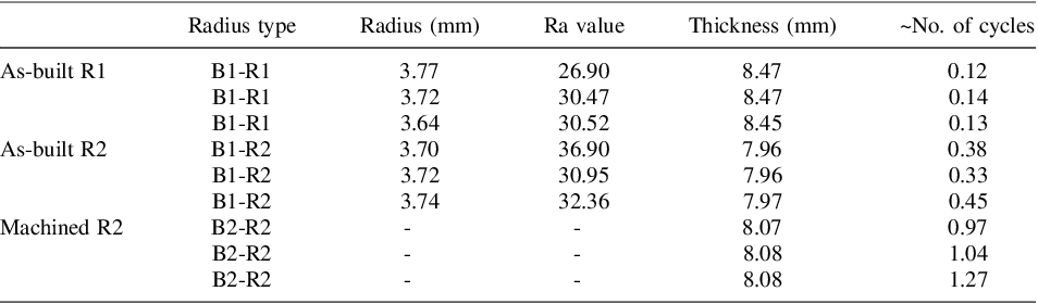
Six of the ten as-built B1 artefacts and three machined B2 artefacts were cyclically fatigue tested. It was important that the thickness, according to Figure 2, was similar for each artefact type to ensure a relevant comparison of material properties between the as-built and machined artefacts. Therefore, the thickness at the tested radius was recorded. Figure 4 presents the mechanical testing results of the B1 and B2 artefacts, grouped according to the surface condition and tested radius. The normalised mechanical testing results, the tested radii on the artefacts and their thickness, radius and Ra measurements are displayed in Table 4.
Cyclic fatigue testing normalised results of B artefacts tested as-built at R1 (red), as-built at R2 (yellow), and machined at R2 (blue)

Artefact B fatigue testing normalised data

A visual inspection of the artefact following fatigue testing revealed that failure occurred on the radial axis, as shown in Figure 3. At this point, the artefact was deemed representative of the uncertainty, allowing investigation into the design-roughness-properties relationship for this radius feature. An indication of the impact of the surface roughness on the fatigue properties could then be obtained by dividing the average number of cycles for the rough surfaces by the reference machined surface according to the fatigue results. The ratios obtained were 0.12 for the horizontal roof radius R1 and 0.36 for the vertical R2 radius. These ratios give a designer an idea of the design features properties, ranging from the ideal case (a machined radius built with no overhang in the build direction) to the realistic case (an as-built, unsupported overhang radius). These results highlight the need for design-related fatigue property understanding in LPBF, as the results demonstrate that the roughness in the unsupported area significantly affects fatigue.
4.4. Fractography
Fractography was conducted on the artefacts to investigate the relationship between surface roughness and fatigue in more detail. An overview of the fracture surfaces of the different surface conditions and radii is shown in Figure 5. As shown in Table 2, the as-built R1 and R2 radii exhibit different surface properties. The R1 roof surface shows a rougher surface with more irregularities than the R2 reference surface; see Figure 5 a) and b). The surface condition is also suggested to be the reason for the number of crack initiation sites along the inner surface. Both R1 and R2 exhibit multiple initiation sites. However, the roof surface of R1 has more initiation sites than the side surface of R2. In contrast to the as-built samples, the fracture surface of the artefacts with a machined inner radius indicates fewer crack initiation sites at the surface, see fracture surface of machined artefact in Figure 5 c). Thus, it is seen that the number of initiation sites increases with the increasing surface roughness.
Images showing the overview appearance of the fracture surfaces, a) R1 (roof) radius of the as-built B1 surface, b) R2 (ref) radius of as-built B1 surface, c) R2 (side) radius of machined B2 surface

4.5. Microstructure characterisation
The typical appearance of the microstructure is shown in Figure 6a), which resembles what has previously been reported for LPBF In718, with elongated grains aligned in the building direction growing through several layers (Ma et al., 2020). When comparing the roof and side radius, the crack in the roof radius (R1) grows parallel with the elongated grains, whilst the crack in the side radius (R2) cuts the grains, see Figure 6b) and c). The fatigue crack growth properties concerning grain orientation have previously been studied by others (Ma et al., 2020), reporting results indicating a higher fatigue crack growth rate parallel to the elongated grains, agreeing with what is shown in the present study. Besides the surface roughness, the anisotropic microstructure most likely contributes to the significant variation in fatigue properties in the different orientations. A fatigue crack propagation parallel to the elongated grains has fewer local barriers, i.e., grain boundaries, that temporarily could arrest the crack; thus, a higher crack propagation rate is expected for the artefacts tested in the roof section. However, in general, the results of the present study are in good agreement with earlier reports on the influence of surface roughness and microstructural characteristics of AM material (Reference Pegues, Roach, Williamson and ShamsaeiKahlin et al., 2020; Reference Kahlin, Ansell, Basu, Kerwin, Newton, Smith and MoverarePegues et al., 2018).
a) Typical microstructure appearance, showing elongated grains aligned with the build direction and extending across multiple layers, b) Crack propagation parallel to the elongated grains in the B1-R1 radius, c) Crack propagation across the elongated grains in the B1-R2 radius

5. Discussion
Using design artefacts designers can gain an additional understanding of design and material properties. In this case study, artefacts were used to investigate the impact of roughness on the material properties of a 4 mm unsupported roof radius design. Additionally, microstructure and fractography analyses were conducted, as these are known factors for fatigue and relate to roughness. The fatigue ratios obtained provide a designer with insights into the material properties of an unsupported as-built radius, offering a clearer understanding of surface roughness effects on fatigue life. The microstructure and fracture initiation results confirmed the impact of grain structure and defects by revealing how these factors affect the mechanical behaviour in the design region. With this information, designers can evaluate design tolerances and modify the product design to compensate for the impact on properties and guide discussions on post-processing options. It also enables designers to balance post-processing requirements with other adjustments, like modifying parameters, like part orientation, to optimise grain structure and improve fatigue life. Hence, the artefact approach can improve the product development process through a more efficient investigation of design ideas in the early phase or a more specific investigation of a specific design uncertainty in the later stages. In this case, changing the build orientation to address grain structure was not feasible. If grain structure had been the primary focus of the investigation, significant adjustments to the artefact design and testing would have been required.
Artefacts focus on quick iterations, allowing designers to gain insights on design uncertainties early on to better understand their design’s implications, hence reducing uncertainty to mitigate problems. The artefact must provide a faithful representation of the uncertainty it aims to address to gain this insight, as it determines the correctness of the results. The testing results show the artefact’s behaviour was as expected for the properties of the radii; however, further investigation may be required to confirm their representativeness of the roof, i.e. will the roof behave as the artefact, and what would have happened if the artefact was varied to be a wider radius or slightly different geometry with the same design feature. Artefacts were used here in an iterative prototyping approach to investigate surface roughness uncertainties, aligning with the prototyping concepts of Lawrence (2003), who emphasises the principle of “rapid, rough, and right” prototypes. Here, the artefacts demonstrate this approach’s “rapid” and “rough” principles.
The artefact research presented here involved collaboration between multiple academic departments and a case company. Hence, it was conducted over several months. By contrast, an in-house AMDA investigation could have significantly faster turnaround times for designing, modelling, printing, and testing artefacts. An integrated design-production-testing loop is required to fully utilise the AMDA approach, ideally done in-house. This integration facilitates a rapid design-test cycle, allowing artefacts to provide practical insights more quickly. This rapid feedback would help early identification of the primary design issues, such as surface roughness, and guide further development more effectively.
This research followed the AMDA process outlined by Dordlofva & Törlind (Reference Dordlofva and rlind2020). However, the AMDA method developed by Obilanade et al. (Reference Obilanade and Dordlofva2024) offers a more detailed approach to using artefacts, including setting artefact evaluation criteria. Evaluation criteria help a designer assess how well an artefact represents the design feature and determine whether the results reduce uncertainty or reveal new ones. While the updated method has not yet been validated, introducing evaluation criteria brings enhanced clarity of the purpose and scope of an artefact, reducing ambiguity around the design insights it provides. A more structured approach gives designers greater confidence in the artefact testing results, enabling better-informed design decisions and enhancing the robustness of the product development process.
6. Conclusions and future work
This paper presents the results of a case study using the AMDA process to assess how design-related surface roughness affects fatigue, employing artefacts as an alternative to full-scale prototyping and extensive parametric feasibility studies. This approach helps bridge gaps in theoretical predictions from software analysis, practical insights from parametric studies and engineer’s expertise. It is advantageous when available AM guidelines or software lacks the necessary design knowledge or material data when time or resources are limited. This work demonstrates how the AMDA method can be applied to explore and investigate design uncertainties versatilely, highlighting the current limitations in design for additive manufacturing. By providing a detailed example of the use of AMDAs and the potential for design knowledge gained, this work demonstrates how AMDAs can be applied to explore other design uncertainties, thereby advancing the field of DfAM and contributing to the broader scientific discourse on the capabilities and constraints of additive manufacturing. As software tools are still some of the best resources for DfAM, future work should explore how the insights gained from artefacts could be integrated into software to address and validate specific design uncertainties more effectively. Research into artificial intelligence-driven generative design for multi-objective optimisation could help designers select an artefact radius or geometry that balances surface roughness and unsupported angles, integrating modern design support with practical artefact investigations. Additionally, industrial case studies of in-house AMDA method implementation should be conducted to evaluate how artefacts could effectively support product development.
Acknowledgements
The authors acknowledge the financial support from LTU Graduate School of Space Technology and the EU regional growth project RIT (Space for Innovation and Growth). This work is also supported by the NRFP (Swedish National Space Research Programme), funded by SNSA (Swedish National Space Agency) and GKN Aerospace Sweden AB.







 Open access

