


Impact Statement
This research explores the effect of partial slip on the flow of fluids in a microfluidic device called the slip length tribometer (SLT). By using a simplified version of Navier–Stokes equations with the Navier-slip boundary condition, partial slip on the SLT's plates was successfully correlated with experimental measurements. We use the OpenFOAM open-source computational fluid dynamics software to perform more detailed simulations that include the effect of a flow inlet and an outflow at the outer radius between the SLT's plates. The more detailed simulation confirms the experimental measurement and the simplified model and provides a basis for future research on partial slip caused by surface roughness.
1. Introduction
For many flow problems in science or engineering, the no-slip boundary condition is applied to model the interaction between fluid flow and surrounding solid walls (e.g. Reference Spurk and AkselSpurk & Aksel 2019). The no-slip condition states that the fluid velocity at an impermeable wall is identical to the velocity of the wall itself, preventing relative motion between the wall and the fluid molecules at the wall. Even if the no-slip boundary condition is an appropriate model for many technical applications, deviations have been observed for microfluidic flows (cf. Reference Lauga, Brenner and StoneLauga, Brenner & Stone 2007; Reference Neto, Evans, Bonaccurso, Butt and CraigNeto et al. 2005) or dynamic wetting flows, where the breakdown of the no-slip boundary condition has been clearly pointed out by Reference Huh and ScrivenHuh & Scriven (1971). This insight is by no means new, as the slip boundary condition was already postulated by Reference NavierNavier (1822). He postulated that the fluid slips, with a relative velocity being linearly proportional to the shear rate at the wall. Here, the constant of proportionality is the slip length, which, according to Reference Helmholtz and von PiotrowskiHelmholtz & von Piotrowski (1860), can be interpreted as an effective increase in gap clearance. The Navier-slip boundary condition expresses a balance between the friction force (opposing the tangential motion) and the component of the viscous shear force parallel to the solid wall, i.e.
 \begin{equation} -\beta ( \boldsymbol{v} - \boldsymbol{v}_w )_\parallel{ = } \boldsymbol{(Sn)}_{||}. \end{equation}
Here,  $\beta$ is a coefficient describing the amount of friction between liquid and solid particles, $\boldsymbol {S} = \mu (\boldsymbol {\nabla } \boldsymbol {v} + \boldsymbol {\nabla } \boldsymbol {v}^{\textsf {T}})$ is the viscous stress tensor and $\mu$ denotes the dynamic viscosity. Within continuum thermodynamics, (1.1) is the simplest, namely linear, closure to model a priori the unknown relative tangential velocity which appears in the entropy production contribution due to relative (tangential) motion between two phases; see Reference BotheBothe (2022) for more details. Moreover, the solid wall is assumed to be impermeable, which implies that the normal component of the relative velocity vanishes, i.e.
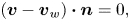 \begin{equation} ( \boldsymbol{v} - \boldsymbol{v}_w ) \boldsymbol{\cdot} \boldsymbol{n} = 0, \end{equation}
where  $\boldsymbol {n}$ denotes the outer normal vector field to the solid wall. Note that the full boundary condition for solving the Navier–Stokes (or Stokes) equations for fluid flow in a confined domain with Navier slip is given by (1.1) and (1.2) together.
An equivalent formulation of (1.1) is obtained by dividing the equation by the friction coefficient, leading to
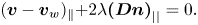 \begin{equation} ( \boldsymbol{v} - \boldsymbol{v}_w )_\parallel{ + } 2 \lambda \boldsymbol{(Dn)}_{||} = 0. \end{equation}
Here,  $\boldsymbol {D}=\frac 12 (\boldsymbol {\nabla } \boldsymbol {v}+ (\boldsymbol {\nabla } \boldsymbol {v})^{\textsf {T}})$ is the rate-of-deformation tensor and the quantity
 \begin{equation} \lambda : = \frac{\mu}{\beta} \end{equation}
is called the slip length. It is known from molecular dynamics simulations (cf. Reference Mehrnia and PelzMehrnia & Pelz 2021) and experimental investigation that the value of the slip length is typically of the order of 10 to 100 nm (see Reference Zhu and GranickZhu & Granick 2002; Reference Bonaccurso, Butt and CraigBonaccurso, Butt & Craig 2003; Reference Granick, Zhu and LeeGranick, Zhu & Lee 2003; Reference Neto, Evans, Bonaccurso, Butt and CraigNeto et al. 2005; Reference Vinogradova and YakubovVinogradova & Yakubov 2006). Hence, the slip length is far below the characteristic length scales of the flow for many technical applications. Furthermore, the impact of  $\lambda$ on the macroscopic flow may be small, particularly for single-phase flows. However, for dynamic wetting flows or flow processes where the characteristic length scale is of the order of the slip length, e.g. sealing systems and hydraulic components, it is important to determine the value of the slip parameter. More details of the latest research can be found in the review articles by Reference Neto, Evans, Bonaccurso, Butt and CraigNeto et al. (2005), Reference Cao, Sun, Chen and GuoCao et al. (2009), Reference Vinogradova and BelyaevVinogradova & Belyaev (2011) and Reference Pelz, Corneli, Mehrnia and KuhrPelz et al. (2022). Here, the slip parameter is of the order of magnitude of the prescribing surface roughness. It is stated, especially by Reference Pelz, Corneli, Mehrnia and KuhrPelz et al. (2022), that most of the experimental techniques used to measure the slip parameter are inadequate for determining slip length for technically relevant rough surfaces. This is mainly due to the small characteristic length scale of the measurement device, being of the order of 10 $\mathrm {\mu }$m. To adequately measure the slip length for large surface roughnesses, a much higher characteristic length scale of the system is needed.
For this reason, the slip length tribometer (SLT) was developed (see Reference Pelz, Corneli, Mehrnia and KuhrPelz et al. (2022) and Reference CorneliCorneli (2022) for details). The SLT is a plate–plate tribometer designed to measure both the lubrication gap height and the frictional torque transmitted from the rotating plate, through the entrapped liquid, to the stationary plate. It overcomes limitations of existing devices like the surface force apparatus (Reference Horn, Vinogradova, Mackay and Phan-ThienHorn et al. 2000) and the atomic force microscope (Reference Henry and CraigHenry & Craig 2009), particularly in characterizing technically relevant rough surfaces at varying temperatures. The SLT can analyse machined surfaces with arithmetic mean roughnesses ranging from  $10 \ \mathrm {nm}$ to $1 \ \mathrm {\mu }\mathrm {m}$, across temperatures from $-30$ to $100\,^\circ \mathrm {C}$. Its ability to handle such large roughnesses is largely due to the significant characteristic length scale, i.e. the diameter of the plates, being of the order of 10 mm. This results in a wetted area of approximately $3 \times 10^3\ \mathrm {mm}^2$, which is six orders of magnitude greater than that of existing apparatus for wall slip measurements, enabling an in situ reduction of uncertainty. Additional reduction of overall uncertainty is achieved through in situ calibration of the capacitive position sensors using an interferometric white-light thickness measurement device. Furthermore, stochastic uncertainty is minimized through an automated measurement process, utilizing between 300 and 800 measurement points, where each point is averaged over 70 000 individual measurements within a 10 s interval for a single slip length measurement.
The slip length is derived by using an analytical solution of Navier–Stokes equations with Navier-slip boundary condition for a Couette-type flow between two rotating plates, cf. (1.5), relating the measured torque and gap height to the slip length itself.
However, the simplified approach, derived from a solution of the Stokes equation, neglects the feed flow entering and leaving the device during measurement. Therefore, the main goal of the present work is to show, utilizing computational fluid dynamics simulations in the open-source software OpenFOAM-v2312 (2023) (see Reference Marić, Höpken and MooneyMarić, Höpken & Mooney (2014) for workings and usage of OpenFOAM), that the simplified analytical model
 \begin{equation} M = \frac{\mu I_p \varOmega}{h + 2\lambda} \end{equation}
for the torque  $M$ as a function of the plate distance $h$, the polar moment of the area $I_p = {{\rm \pi} }R^4/2$ of the lower plate and angular velocity $\varOmega$ is sufficient to infer the slip length $\lambda$ from the experimentally measured torque. The structure of the paper is as follows. In § 2, the simplified analytical model for the torque is presented, followed by a description of the simulation models and set-up. Section 3 discusses the results and provides a comparative analysis of the employed models. The presented work is then summarized in § 4.
2. Materials and methods
2.1 Analytical model
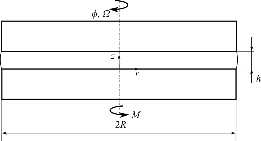
We consider the steady and rotationally symmetric flow of an incompressible Newtonian fluid between two plates of radius R. The upper plate rotates with constant angular velocity  $\varOmega$. The lower plate is at rest. Let $(r, \phi, z)$ be the cylindrical coordinates so that the plates are at $z = 0$ and
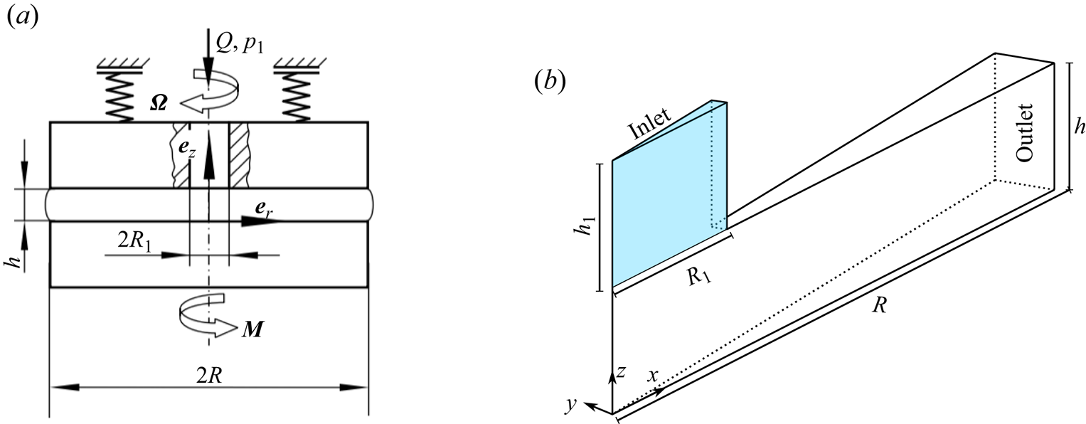
  $z = h$. Figure 1 shows a sketch of the tribometer.
Sketch of the principle of the analytical model (see Reference CorneliCorneli (2022) for details).
2.1.1 Equations of motion
Compared with the work of Reference CorneliCorneli (2022), where a simpler linear model is assumed, we apply Navier-slip boundary conditions to full steady-state Navier–Stokes equations in cylindrical coordinates.
We introduce the velocity vector  $\boldsymbol {v}=v_r \boldsymbol {e_r}+v_{\phi } \boldsymbol {e_{\phi }}+v_z \boldsymbol {e_z}$ and the pressure $p$. Considering the rotational symmetry, the Navier–Stokes equations have the following form (Reference Spurk and AkselSpurk & Aksel 2019):
 \begin{gather} \frac{\partial v_r}{\partial r} + \frac{\partial v_z}{\partial z} + \frac{v_r}{r} = 0, \end{gather}
 \begin{gather}v_r \frac{\partial v_r}{\partial r} + v_z \frac{\partial v_r}{\partial z} - \frac{v_{\phi}^2}{r} = {-}\frac{1}{\rho} \frac{\partial p}{\partial r} + \nu \left(\frac{\partial^2 v_r}{\partial r^2} + \frac{1}{r}\frac{\partial v_r}{\partial r} - \frac{v_r}{r^2} + \frac{\partial^2 v_r}{\partial z^2} \right), \end{gather}
 \begin{gather}v_r \frac{\partial v_{\phi}}{\partial r} + v_z \frac{\partial v_{\phi}}{\partial z} + \frac{v_r v_{\phi}}{r} = \nu \left(\frac{\partial^2 v_{\phi}}{\partial r^2} + \frac{1}{r}\frac{\partial v_{\phi}}{\partial r} - \frac{v_{\phi}}{r^2} + \frac{\partial^2 v_{\phi}}{\partial z^2} \right), \end{gather}
 \begin{gather}v_r \frac{\partial v_z}{\partial r} + v_z \frac{\partial v_z}{\partial z} = {-}\frac{1}{\rho} \frac{\partial p}{\partial z} + \nu \left(\frac{\partial^2 v_z}{\partial r^2} + \frac{1}{r}\frac{\partial v_z}{\partial r} + \frac{\partial^2 v_z}{\partial z^2} \right). \end{gather}
Here,  $\rho$ denotes the density and $\nu$ is the kinematic viscosity.
2.1.2 Non-dimensionalization of the equations of motion
The plate radius  $R$ and the gap width $h$ are the characteristic lengths used to non-dimensionalize the equations. We define the dimensionless variables
 \begin{equation} \hat{r} : = \frac{r}{R}, \quad \hat{z} : = \frac{z}{h}, \quad \hat{v}_r : = \frac{v_r}{R \varOmega}, \quad \hat{v}_{\phi} : = \frac{v_{\phi}}{R \varOmega}, \quad \hat{v}_z: = \frac{v_z}{h \varOmega}, \quad \hat{p}: = \frac{p}{\rho R^2 \varOmega^2}. \end{equation}
Substituting the dimensionless variables into the dimensioned equations (2.1)–(2.4) yields the dimensionless system of equations as
 \begin{gather} \frac{\partial \hat{v}_r}{\partial \hat{r}} + \frac{\partial \hat{v}_z}{\partial \hat{z}} + \frac{\hat{v}_r}{\hat{r}} = 0, \end{gather}
 \begin{gather}\hat{v}_r \frac{\partial
\hat{v}_r}{\partial \hat{r}} + \hat{v}_z \frac{\partial
\hat{v}_z}{\partial \hat{z}} -
\frac{\hat{v}_{\phi}^2}{\hat{r}} = {-} \frac{\partial
\hat{p}}{\partial \hat{r}} + \frac{1}{Re} \left[ \delta^2
\left( \frac{\partial^2 \hat{v}_r}{\partial \hat{r}^2} +
\frac{1}{\hat{r}}\frac{\partial \hat{v}_r}{\partial
\hat{r}} - \frac{\hat{v}_r}{\hat{r}^2} \right) +
\frac{\partial^2 \hat{v}_r}{\partial \hat{z}^2} \right],
\end{gather}
\begin{gather}\hat{v}_r \frac{\partial
\hat{v}_r}{\partial \hat{r}} + \hat{v}_z \frac{\partial
\hat{v}_z}{\partial \hat{z}} -
\frac{\hat{v}_{\phi}^2}{\hat{r}} = {-} \frac{\partial
\hat{p}}{\partial \hat{r}} + \frac{1}{Re} \left[ \delta^2
\left( \frac{\partial^2 \hat{v}_r}{\partial \hat{r}^2} +
\frac{1}{\hat{r}}\frac{\partial \hat{v}_r}{\partial
\hat{r}} - \frac{\hat{v}_r}{\hat{r}^2} \right) +
\frac{\partial^2 \hat{v}_r}{\partial \hat{z}^2} \right],
\end{gather} \begin{gather}\hat{v}_r \frac{\partial \hat{v}_{\phi}}{\partial \hat{r}} + \hat{v}_z \frac{\partial \hat{v}_{\phi}}{\partial \hat{z}} + \frac{\hat{v}_r \hat{v}_{\phi}}{\hat{r}} = \frac{1}{Re} \left[ \delta^2 \left( \frac{\partial^2 \hat{v}_{\phi}}{\partial \hat{r}^2} + \frac{1}{\hat{r}}\frac{\partial \hat{v}_{\phi}}{\partial \hat{r}} - \frac{\hat{v}_{\phi}}{\hat{r}^2} \right) + \frac{\partial^2 \hat{v}_{\phi}}{\partial \hat{z}^2} \right], \end{gather}
 \begin{gather}\hat{v}_r \frac{\partial \hat{v}_z}{\partial \hat{r}} + \hat{v}_z \frac{\partial \hat{v}_z}{\partial \hat{z}} = {-} \frac{1}{\delta^2} \frac{\partial \hat{p}}{\partial \hat{z}} + \frac{1}{Re} \left[ \delta^2 \left( \frac{\partial^2 \hat{v}_z}{\partial \hat{r}^2} + \frac{1}{r}\frac{\partial \hat{v}_z}{\partial \hat{r}}\right) + \frac{\partial^2 \hat{v}_z}{\partial \hat{z}^2} \right]. \end{gather}
The non-dimensional parameters used in this study are the Reynolds number  $Re=({h^2 \varOmega })/{\nu }$ and the plate spacing $\delta ={h}/{R}$. According to the operation parameters of the SLT, the Reynolds number is of the order of $10^{-9}$. Therefore, the inertial terms can be neglected, and the following Stokes equations apply:
 \begin{gather} \frac{\partial \hat{v}_r}{\partial \hat{r}} + \frac{\partial \hat{v}_z}{\partial \hat{z}} + \frac{\hat{v}_r}{\hat{r}} = 0, \end{gather}
 \begin{gather}- \frac{\partial \hat{p}}{\partial \hat{r}} + \frac{1}{Re} \left[ \delta^2 \left( \frac{\partial^2 \hat{v}_r}{\partial \hat{r}^2} + \frac{1}{\hat{r}}\frac{\partial \hat{v}_r}{\partial \hat{r}} - \frac{\hat{v}_r}{\hat{r}^2} \right) + \frac{\partial^2 \hat{v}_r}{\partial \hat{z}^2} \right] = 0, \end{gather}
 \begin{gather}\frac{1}{Re} \left[ \delta^2 \left( \frac{\partial^2 \hat{v}_{\phi}}{\partial \hat{r}^2} + \frac{1}{\hat{r}}\frac{\partial \hat{v}_{\phi}}{\partial \hat{r}} - \frac{\hat{v}_{\phi}}{\hat{r}^2} \right) + \frac{\partial^2 \hat{v}_{\phi}}{\partial \hat{z}^2} \right] = 0, \end{gather}
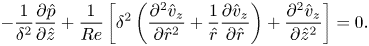 \begin{gather}- \frac{1}{\delta^2} \frac{\partial \hat{p}}{\partial \hat{z}} + \frac{1}{Re} \left[ \delta^2 \left( \frac{\partial^2 \hat{v}_z}{\partial \hat{r}^2} + \frac{1}{\hat{r}}\frac{\partial \hat{v}_z}{\partial \hat{r}}\right) + \frac{\partial^2 \hat{v}_z}{\partial \hat{z}^2} \right] = 0. \end{gather}
It should be emphasized that (2.12) is uncoupled and can be solved independently. Since we are only interested in the torque at the bottom plate resulting from the shear stress  $\tau _{\phi z}=\mu ({\partial v_{\phi }}/{\partial z})$, only the circumferential velocity component $\hat {v}_\phi (\hat {r},\hat {z})$ will be computed. For simplicity, the circumferential velocity component $\hat {v}_\phi (\hat {r},\hat {z})$ is denoted as $\hat {v}(\hat {r},\hat {z})$. The equation
 \begin{equation} \delta^2 \left( \frac{\partial^2 \hat{v}}{\partial \hat{r}^2} + \frac{1}{\hat{r}}\frac{\partial \hat{v}}{\partial \hat{r}} - \frac{\hat{v}}{\hat{r}^2} \right) + \frac{\partial^2 \hat{v}}{\partial \hat{z}^2} = 0\end{equation}
is solved in the following.
2.1.3 Boundary conditions
In order to solve the equation of motion (2.14) uniquely, the boundary conditions must be specified. The Navier-slip boundary condition is applied at the plates, and considering the rotational symmetry, the following boundary conditions apply:
 \begin{gather} \hat{v}(\hat{r} = 0,\hat{z}) = 0, \end{gather}
 \begin{gather}- \left.\frac{\lambda_u}{h} \frac{\partial \hat{v}(\hat{r},\hat{z})}{\partial \hat{z}} \right|_{\hat{z} = 0} + \hat{v}(\hat{r},\hat{z} = 0) = 0 \end{gather}
and
 \begin{equation} \left.\frac{\lambda_o}{h} \frac{\partial \hat{v}(\hat{r},\hat{z})}{\partial \hat{z}} \right|_{\hat{z} = 1} + \hat{v}(\hat{r},\hat{z} = 1) = \hat{r}. \end{equation}
2.1.4 Analytical solution
Substituting  $\hat {v}=\hat {r} f(\hat {z})$ in the differential equation (2.14), with which the symmetry condition (2.15) is automatically satisfied, leads to
 \begin{equation} \frac{\partial^2 f(\hat{z})}{\partial \hat{z}^2} = 0.\end{equation}
The boundary conditions (2.16) and (2.17) simplify to
 \begin{equation} - \left.\frac{\lambda_u}{h} \frac{\partial \hat{f}(\hat{z})}{\partial \hat{z}} \right|_{\hat{z} = 0} + \hat{f}(0) = 0 \end{equation}
and
 \begin{equation} \left.\frac{\lambda_o}{h} \frac{\partial \hat{f}(\hat{z})}{\partial \hat{z}} \right|_{\hat{z} = 1} + \hat{f}(1) = 1. \end{equation}
The integration of the differential equation (2.18) considering the boundary conditions (2.19) and (2.20) leads to the velocity profile
 \begin{equation} \hat{v}(\hat{r},\hat{z}) = \frac{\hat{r}}{1 + (\lambda_o + \lambda_u)/h}\left(\hat{z} + \frac{\lambda_u}{h} \right). \end{equation}
Since the fluid is Newtonian, the shear stress  $\tau _{\phi z}$ (see Reference Spurk and AkselSpurk & Aksel (2019) for details) can be expressed as
 \begin{equation} \tau_{\phi z} = \mu \frac{\partial v_{\phi}}{\partial z} = \frac{\mu \varOmega r}{h + \lambda_u + \lambda_o}. \end{equation}
By integrating the shear stress  $\tau _{\phi z}$ over the area of the bottom plate, the torque becomes
 \begin{equation} M = \int_{\phi = 0}^{\phi = 2{\rm \pi}} \int_{r = 0}^{r = R} r\tau_{\phi z} r \, \mathrm{d}r \, \mathrm{d}\phi = \frac{\mu I_p \varOmega}{h + \lambda_u + \lambda_o}.\end{equation}
For this study, we consider a homogeneous material for both rheometer plates; hence, the slip length is assumed to be equal for both plates. In this case, the formula for the torque simplifies to (1.5).
For a given measured torque at a specific gap height  $h$, the linear relationship (1.5) between $M^{-1}$ and $h$ provides the value of slip length (see Reference Kuhr, Corneli and PelzKuhr, Corneli & Pelz (2022) and Reference Pelz, Corneli, Mehrnia and KuhrPelz et al. (2022) for details).
2.2 Simulation model
Figure 2(a) shows a sketch of the principle of the SLT, simulated using the open-source software (OpenFOAM-v2312 2023). Two simulation models are presented: the actual model and the simplified model. The actual model has a cylindrical tube that drives the fluid between the plates, through which the fluid (density  $\rho$, dynamic viscosity $\mu$) flows in with constant volumetric flow rate $Q$ at pressure $p_1$. The actual simulation model is used to estimate the effect of the cylindrical tube on the resulting torque. The cylindrical tube is modelled as a hole (radius $R_1$) in the simplified simulation model and the inlet is present at the top rheometer plate. A schematic diagram of the axisymmetric computational domain is shown in figure 2(b). At the outlet, the fluid leaves the computational domain. At the solid boundary, the simulation utilizes the OpenFOAM implementation of Navier slip developed by Reference Gründing, Raju and MaricGründing, Raju & Maric (2022) with the slip length provided by the analytical model.
(a) Sketch of the principle of the simulation model (see Reference CorneliCorneli (2022) for details). (b) Schematic diagram of an axisymmetric domain of the actual model with the tribometer radius  $R$, gap height $h$, an inlet height $h_1$ and inlet radius $R_1$. For the simplified simulation model, the inlet is present at the top tribometer plate, i.e. the blue region is excluded from the computational domain.
2.2.1 Equations of motion
Since OpenFOAM does not support the formulation of the balance equations in cylindrical coordinates, we consider the Navier–Stokes equations in Cartesian coordinates.
For the velocity vector  $\boldsymbol {v}=[v_x, v_y, v_z]^{\textsf {T}})$ and the pressure $p$, the following balance equations for mass and momentum (Reference Spurk and AkselSpurk & Aksel 2019) apply in the computational domain:
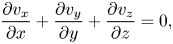 \begin{gather} \frac{\partial v_x}{\partial x} + \frac{\partial v_y}{\partial y} + \frac{\partial v_z}{\partial z} = 0, \end{gather}
 \begin{gather} \left.\begin{array}{c}
\displaystyle \rho \left( v_x \dfrac{\partial v_x}{\partial
x} + v_y \dfrac{\partial v_x}{\partial y} + v_z
\dfrac{\partial v_x}{\partial z} \right) =
{-}\dfrac{\partial p}{\partial x} + \mu \left(
\dfrac{\partial^2 v_x}{\partial x^2} + \dfrac{\partial^2
v_x}{\partial y^2} + \dfrac{\partial^2 v_x}{\partial z^2}
\right), \\ \displaystyle \rho \left( v_x \dfrac{\partial
v_y}{\partial x} + v_y \dfrac{\partial v_y}{\partial y} +
v_z \dfrac{\partial v_y}{\partial z} \right) =
{-}\dfrac{\partial p}{\partial y} + \mu \left(
\dfrac{\partial^2 v_y}{\partial x^2} + \dfrac{\partial^2
v_y}{\partial y^2} + \dfrac{\partial^2 v_y}{\partial z^2}
\right), \\ \displaystyle \rho \left( v_x \dfrac{\partial
v_z}{\partial x} + v_y \dfrac{\partial v_z}{\partial y} +
v_z \dfrac{\partial v_z}{\partial z} \right) =
{-}\dfrac{\partial p}{\partial z} + \mu \left(
\dfrac{\partial^2 v_z}{\partial x^2} + \dfrac{\partial^2
v_z}{\partial y^2} + \dfrac{\partial^2 v_z}{\partial z^2}
\right). \end{array}\right\}
\end{gather}
\begin{gather} \left.\begin{array}{c}
\displaystyle \rho \left( v_x \dfrac{\partial v_x}{\partial
x} + v_y \dfrac{\partial v_x}{\partial y} + v_z
\dfrac{\partial v_x}{\partial z} \right) =
{-}\dfrac{\partial p}{\partial x} + \mu \left(
\dfrac{\partial^2 v_x}{\partial x^2} + \dfrac{\partial^2
v_x}{\partial y^2} + \dfrac{\partial^2 v_x}{\partial z^2}
\right), \\ \displaystyle \rho \left( v_x \dfrac{\partial
v_y}{\partial x} + v_y \dfrac{\partial v_y}{\partial y} +
v_z \dfrac{\partial v_y}{\partial z} \right) =
{-}\dfrac{\partial p}{\partial y} + \mu \left(
\dfrac{\partial^2 v_y}{\partial x^2} + \dfrac{\partial^2
v_y}{\partial y^2} + \dfrac{\partial^2 v_y}{\partial z^2}
\right), \\ \displaystyle \rho \left( v_x \dfrac{\partial
v_z}{\partial x} + v_y \dfrac{\partial v_z}{\partial y} +
v_z \dfrac{\partial v_z}{\partial z} \right) =
{-}\dfrac{\partial p}{\partial z} + \mu \left(
\dfrac{\partial^2 v_z}{\partial x^2} + \dfrac{\partial^2
v_z}{\partial y^2} + \dfrac{\partial^2 v_z}{\partial z^2}
\right). \end{array}\right\}
\end{gather}2.2.2 Boundary conditions
The Navier-slip boundary condition and the condition of impermeability hold at the bottom and top plates and the inlet channel wall, and they can then be expressed in the form
 \begin{gather} - \lambda_u
\left(\begin{array}{c} \displaystyle \dfrac{\partial
v_x}{\partial z} + \dfrac{\partial v_z}{\partial x} \\
\displaystyle \dfrac{\partial v_y}{\partial z} +
\dfrac{\partial v_z}{\partial y} \\ 0 \end{array}\right)_{z
= 0} + \left(\begin{array}{c} v_x \\ v_y \\ v_z
\end{array}\right)_{z = 0} = \left(\begin{array}{c} 0 \\ 0
\\ 0\end{array}\right),
\end{gather}
\begin{gather} - \lambda_u
\left(\begin{array}{c} \displaystyle \dfrac{\partial
v_x}{\partial z} + \dfrac{\partial v_z}{\partial x} \\
\displaystyle \dfrac{\partial v_y}{\partial z} +
\dfrac{\partial v_z}{\partial y} \\ 0 \end{array}\right)_{z
= 0} + \left(\begin{array}{c} v_x \\ v_y \\ v_z
\end{array}\right)_{z = 0} = \left(\begin{array}{c} 0 \\ 0
\\ 0\end{array}\right),
\end{gather} \begin{gather}\lambda_o
\left(\begin{array}{c} \displaystyle \dfrac{\partial
v_x}{\partial z} + \dfrac{\partial v_z}{\partial x} \\
\displaystyle \dfrac{\partial v_y}{\partial z} +
\dfrac{\partial v_z}{\partial y} \\ 0 \end{array}\right)_{z
= h} + \left(\begin{array}{c} v_x \\ v_y \\ v_z
\end{array}\right)_{z = h} = \left(\begin{array}{c} 0 \\ r
\varOmega \\ 0\end{array}\right)_{z = h},
\end{gather}
\begin{gather}\lambda_o
\left(\begin{array}{c} \displaystyle \dfrac{\partial
v_x}{\partial z} + \dfrac{\partial v_z}{\partial x} \\
\displaystyle \dfrac{\partial v_y}{\partial z} +
\dfrac{\partial v_z}{\partial y} \\ 0 \end{array}\right)_{z
= h} + \left(\begin{array}{c} v_x \\ v_y \\ v_z
\end{array}\right)_{z = h} = \left(\begin{array}{c} 0 \\ r
\varOmega \\ 0\end{array}\right)_{z = h},
\end{gather} \begin{gather}- \lambda_i
\left(\begin{array}{c} 0 \\ \displaystyle \dfrac{\partial
v_x}{\partial y} + \dfrac{\partial v_y}{\partial x} \\
\displaystyle \dfrac{\partial v_x}{\partial z} +
\dfrac{\partial v_z}{\partial x} \end{array}\right)_{x =
R_1} + \left(\begin{array}{c} v_x \\ v_y \\ v_z
\end{array}\right)_{x = R_1} = \left(\begin{array}{c} 0 \\
0 \\ 0\end{array}\right)_{x = R_1},
\end{gather}
\begin{gather}- \lambda_i
\left(\begin{array}{c} 0 \\ \displaystyle \dfrac{\partial
v_x}{\partial y} + \dfrac{\partial v_y}{\partial x} \\
\displaystyle \dfrac{\partial v_x}{\partial z} +
\dfrac{\partial v_z}{\partial x} \end{array}\right)_{x =
R_1} + \left(\begin{array}{c} v_x \\ v_y \\ v_z
\end{array}\right)_{x = R_1} = \left(\begin{array}{c} 0 \\
0 \\ 0\end{array}\right)_{x = R_1},
\end{gather}
where  $r=\sqrt {x^2+y^2}$ describes the distance between any point $P$ on the upper plate with coordinates $(x,y,h)$ and the axis of rotation of the SLT. At the inlet, a constant pressure of value $p_i$ is applied as a boundary condition, i.e.
 \begin{equation} p(x,y,h + h_1) = p_i \quad \text{for} \ 0 \leq \sqrt{x^2 + y^2} \leq R_1, \end{equation}
where Reference CorneliCorneli (2022) relates  $p_i$ to the plate height $h$ as
 \begin{equation} h = \frac{\rm \pi}{2k} \frac{R^2 - R_1^2}{\ln{(R/R_1)}} p_i. \end{equation}
At the outlet, the ambient pressure is set to zero, i.e.
 \begin{equation} p(x,y,z) = 0 \quad \text{for}\ \sqrt{x^2 + y^2} = R \quad \text{and} \quad 0 \leq z \leq h. \end{equation}
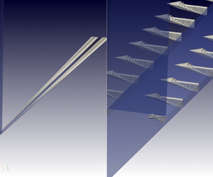
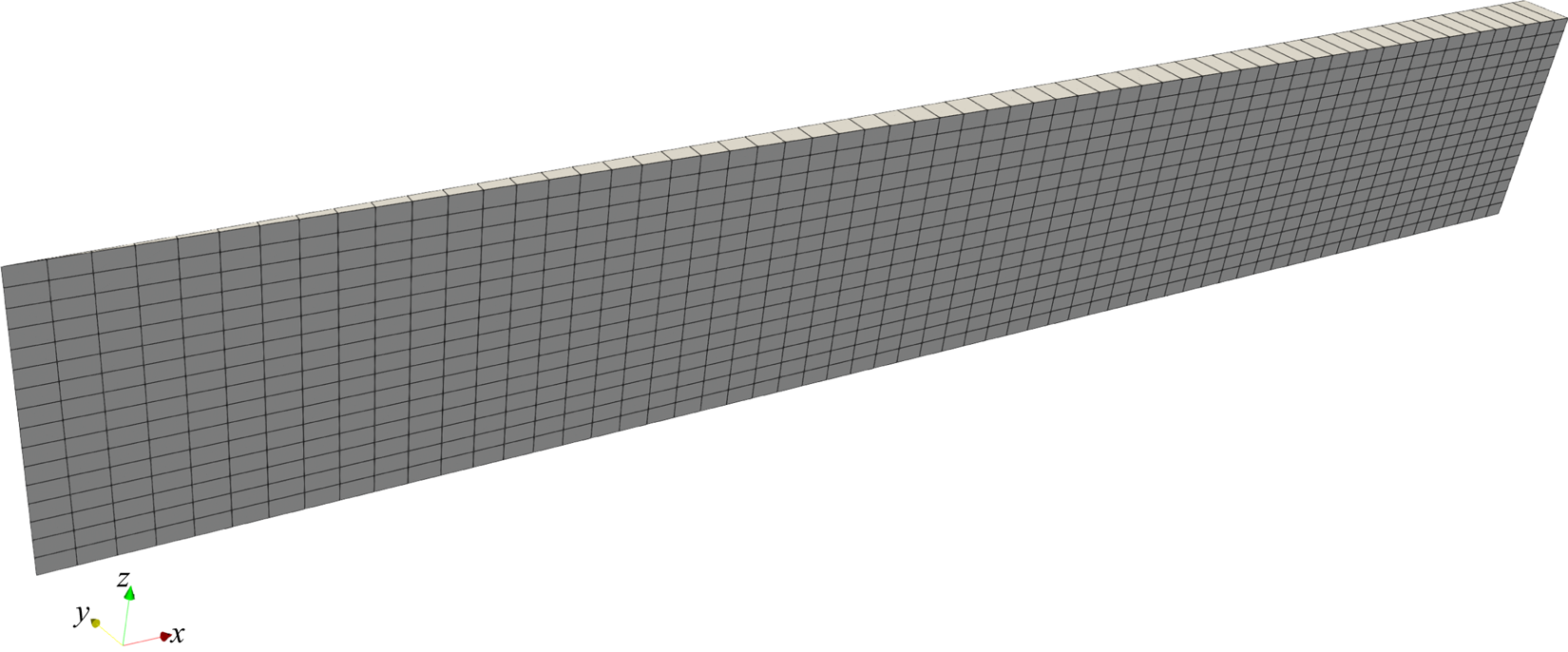
Furthermore, we exploit the rotational symmetry of the problem to save computational effort by simulating only a section of the domain, as shown in figure 2(b). This is done by applying the wedge boundary condition (see Reference Greenshields and WellerGreenshields & Weller (2022) for more details) at the wedge sides of the considered computational domain (cf. figure 3).
Discretized computational domain of the simplified simulation model. The image is scaled in the  $z$ direction to improve the visibility.
2.2.3 Simulation set-up
The presented problem is solved numerically, using the unstructured finite volume method within OpenFOAM, applying the simpleFoam solver for steady-state single-phase Navier–Stokes equations that utilizes the SIMPLE algorithm developed by Reference Caretto, Gosman, Patankar and SpaldingCaretto et al. (1973). The input data of the simulation set-up are publicly available, as well as the post-processing scripts and the secondary data (Reference Pelz, Corneli, Mehrnia and KuhrPelz et al. 2023; Reference Asghar, Marić, Ben Gozlen, Raju, Fricke, Kuhr, Pelz and BotheAsghar et al. 2024).
Due to rotational symmetry of the problem, we consider only a slice of the whole three-dimensional domain (figure 2b). The slice is discretized using a prismatic (wedge) discretization. The angle of the wedge is  $1^{\circ }$ in this study, and the depth of the domain running along the plane of symmetry comprises a single cell, as shown in figure 3. Parameters $N_r$ and $N_z$ denote the number of cells in radial and axial directions, respectively.
3. Results and discussion
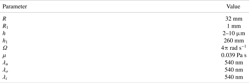
In this section, a convergence study is performed to evaluate the accuracy of the simulation model. Below, the results of both modelling approaches are presented and compared with the measured data. The parameters used for the simulation studies are presented in table 1. The slip length value  $\lambda = \lambda _o = \lambda _u = 540\ \textrm {nm}$ results from fitting experimental measurements to the analytical model (1.5) (see Reference CorneliCorneli (2022) for details). In the following, we aim to validate the analytical model with numerical simulations. Since the inlet is composed of the same material, we will assume that $\lambda _i = \lambda = 540\ \textrm {nm}$.
Parameters of the simulation model.
3.1 Mesh convergence study
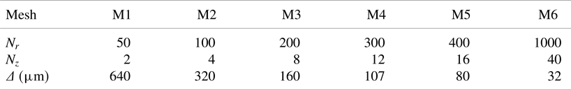
In the following study, the torque on the bottom plate  $M$ is calculated numerically for different mesh sizes, presented in table 2. The mesh width $\varDelta$ is defined by averaging the mesh widths $\varDelta _r$ and $\varDelta _z$ in the radial and axial directions, respectively, and is given as
 \begin{equation} \varDelta = \sqrt{\varDelta_r^2 + \varDelta_z^2} = \sqrt{\left(\frac{R}{N_r}\right)^2 + \left(\frac{h}{N_z}\right)^2}. \end{equation}
Furthermore, the error  $e$ in the torque calculations is defined as
 \begin{equation} e = |M-M_{{ref}}|, \end{equation}
where the reference torque  $M_{{ref}}$ is the torque resulting from the simulation with the finest-resolution mesh M6 (see table 2).
Parameters used in the mesh convergence analysis.
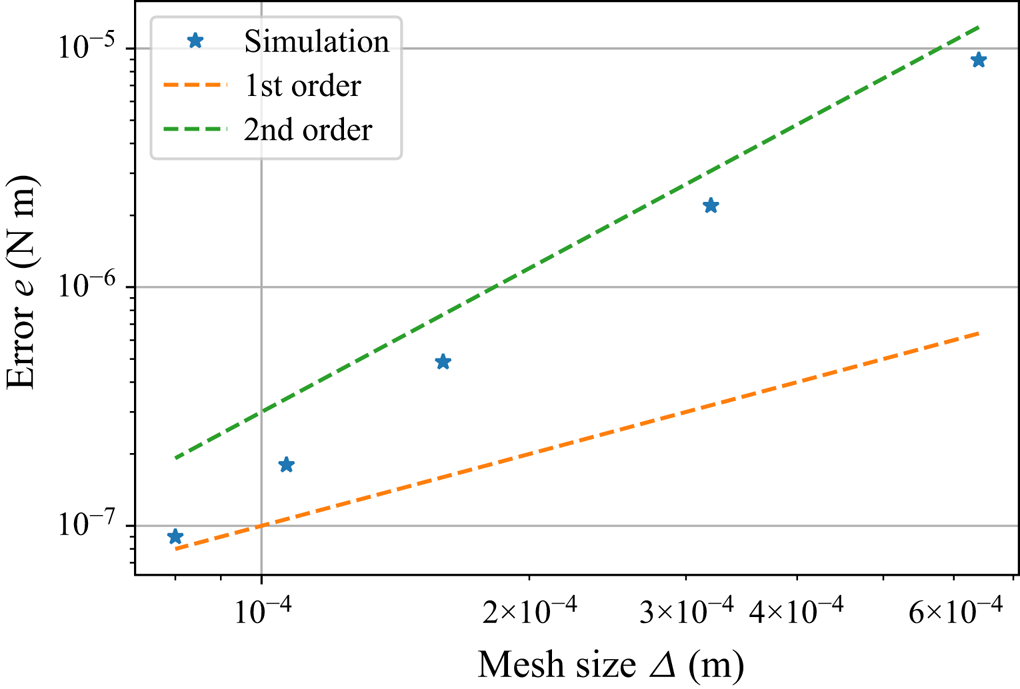
The results of the convergence study are illustrated in figure 4. As expected, the results demonstrate a second-order convergence rate for the error  $e$, given that a second-order discretization method is employed to solve the Navier–Stokes equation. Additionally, the torque $M$ is computed as the integral of the local velocity gradient over the area of the lower plate (see (2.23)).
Convergence analysis for the (simplified) simulation model.
3.2 Simulation results and validation
This section compares the velocity profiles obtained through simulation models with those derived from the analytical model. Moreover, it includes a comparative analysis of the torque values computed from the analytical model, simulations and experimental studies. This section aims to provide insights into the reliability of the models introduced in § 2. The results presented in this section are obtained using mesh M6 (see table 2) and a tribometer plate gap height  $h=5\ \mathrm {\mu }$m. The values from the analytical model are considered as reference values.
3.2.1 Velocity profiles
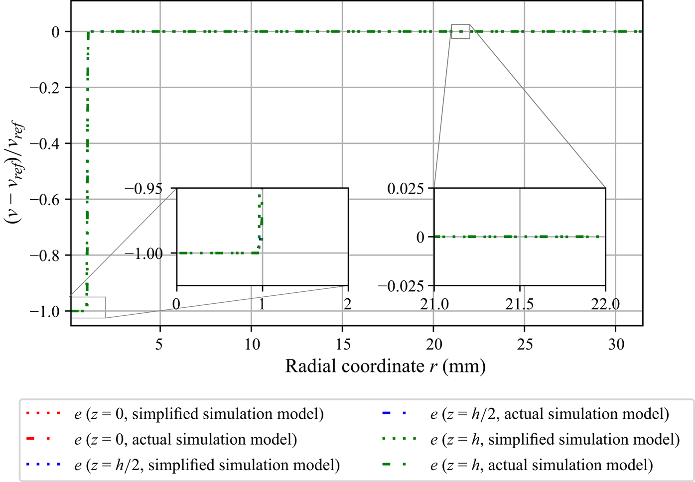
Figure 5 shows the relative error,  $e = (v-v_{{ref}})/v_{{ref}}$, in circumferential velocity $v$ along the radial direction for three different values of $z$. Both simulation models produce similar results, exhibiting that the inlet tube has no impact on the circumferential velocity within the domain. However, the analytical and simulation models differ in the inflow area, as depicted in figure 6. This deviation can be expected because the inflow is not modelled in the analytical model. Moreover, the deviation does not affect the torque at the bottom plate, since the torque depends only on the partial derivative ${\partial v}/{\partial z} |_{z=0}$.
Relative error,  $e = (v-v_{{ref}})/v_{{ref}}$, in the circumferential velocity $v$ along the radial direction for actual and simplified simulation models.
Comparison of the circumferential velocity  $v$ along the radial direction in the inflow region. Even with the presence of an inlet pipe with vanishing axial velocity, the flow almost immediately recovers the analytical model for the circumferential velocity after exiting the inlet.
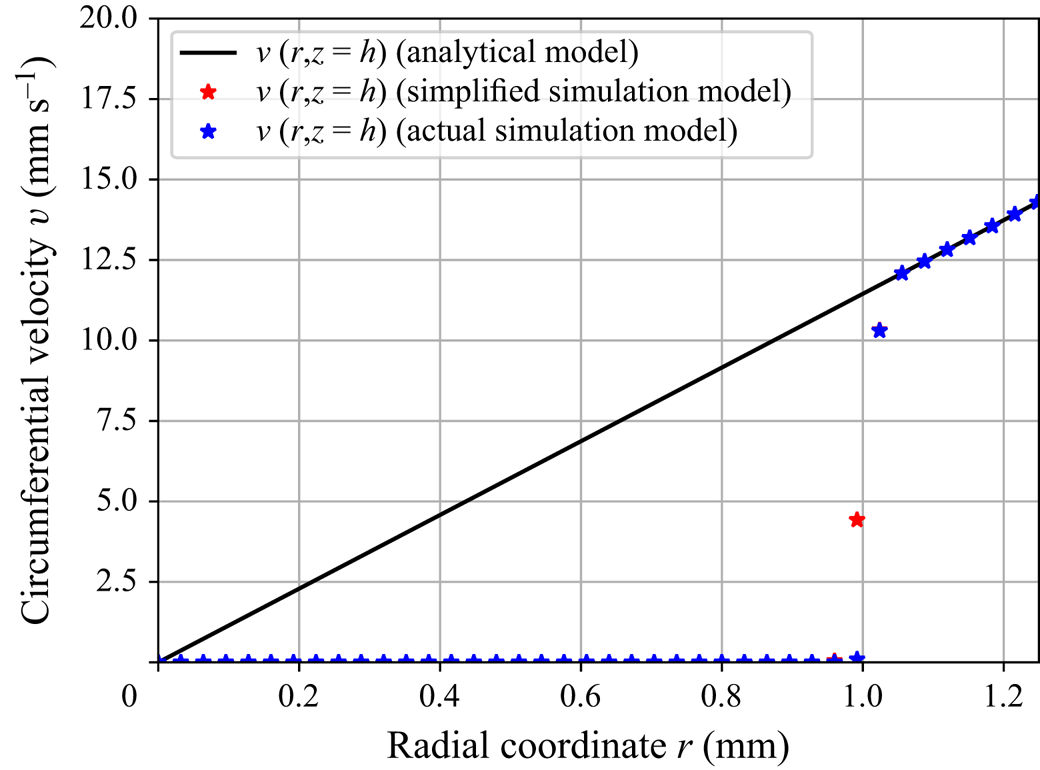
Figure 7 shows the relative error  $e$ in the velocity $v$ calculated along the axial coordinate $z$ for three different values of $r$. While the simulation results are in excellent agreement with the analytical model, a difference between the two simulation models can be observed. Additionally, the root-mean-square (RMS) error in circumferential velocity is presented in table 3.
Relative error  $e$ in the circumferential velocity $v$ along the axial direction for actual and simplified simulation models.

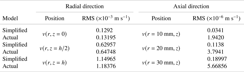
The RMS error in circumferential velocity  $v$ along the radial and axial directions for simulation models with respect to the analytical model.
3.2.2 Torque
The available experimental measurements of torque  $M$ and the tribometer plate gap height $h$, along with the operating parameters listed in table 4, are used to validate the models for torque measurement. The relationship of $M^{-1}$ and $h$ can be very well represented by the linear relation $M^{-1}=bh+a$. The parameters $a$ and $b$ are determined by Reference CorneliCorneli (2022) using the least-squares method.
Operating parameters of the SLT used to validate the models.

The analytical model measures the slip lengths of the upper and lower tribometer plates,  $\lambda _u$ and $\lambda _o$, respectively, and the dynamic viscosity $\mu$ (see (2.23)). Subsequently, the following applies:
 \begin{equation} \left.\begin{array}{c} \lambda_u = \lambda_o = \dfrac{a}{2b}, \\ \mu = \dfrac{1}{b \varOmega I_p}. \end{array}\right\} \end{equation}
Furthermore, these physical parameters are then used to evaluate the analytical and simulation models.
The measurements of the tribometer plate gap height  $h$ and the moment $M$ are subject to errors. In addition, temperature changes in the lubrication gap or variations in motor frequency can distort the measurements. The error propagation of the mentioned errors results in the uncertainties $\delta a$ and $\delta b$ of the parameters $a$ and $b$. From this, the $95\,\%$ confidence interval is derived, within which the measuring points are located with a probability of $95\,\%$.
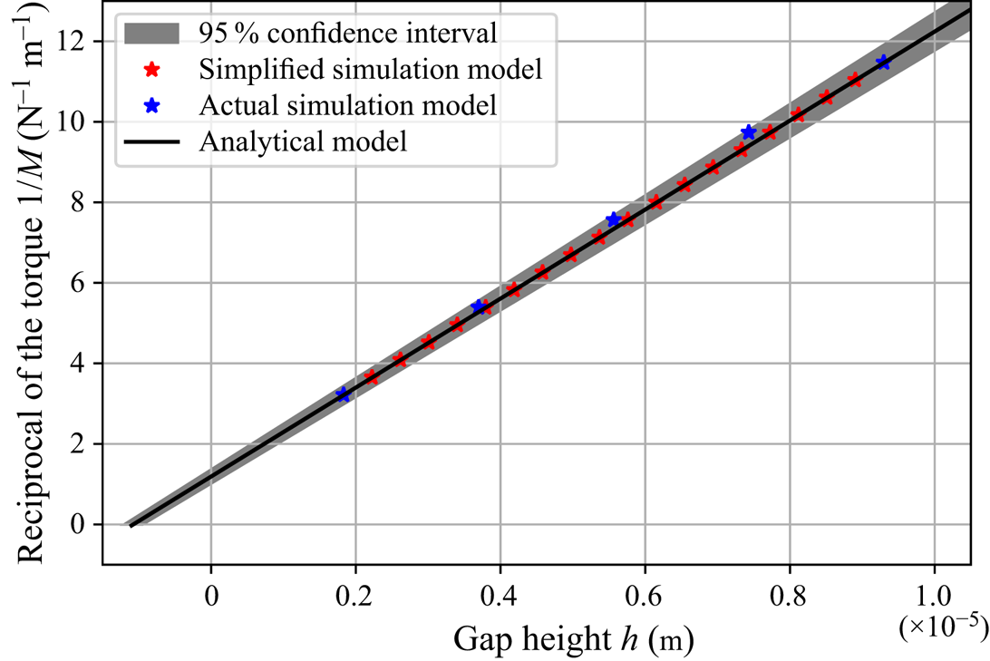
Figure 8 shows the  $95\,\%$ confidence interval of the measured data and the corresponding results of the analytical and simulation models. It is noticeable that the results of both modelling approaches agree very well with the measurement data, showing that the use of the analytical model is justified for evaluating the slip length from the measurements.
Validation of the models with the measurement of the torque  $M$ as a function of the gap height $h$.
$h$.
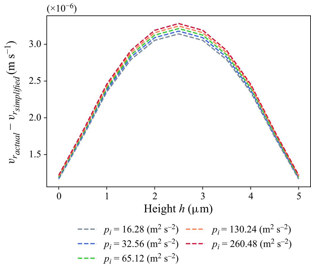
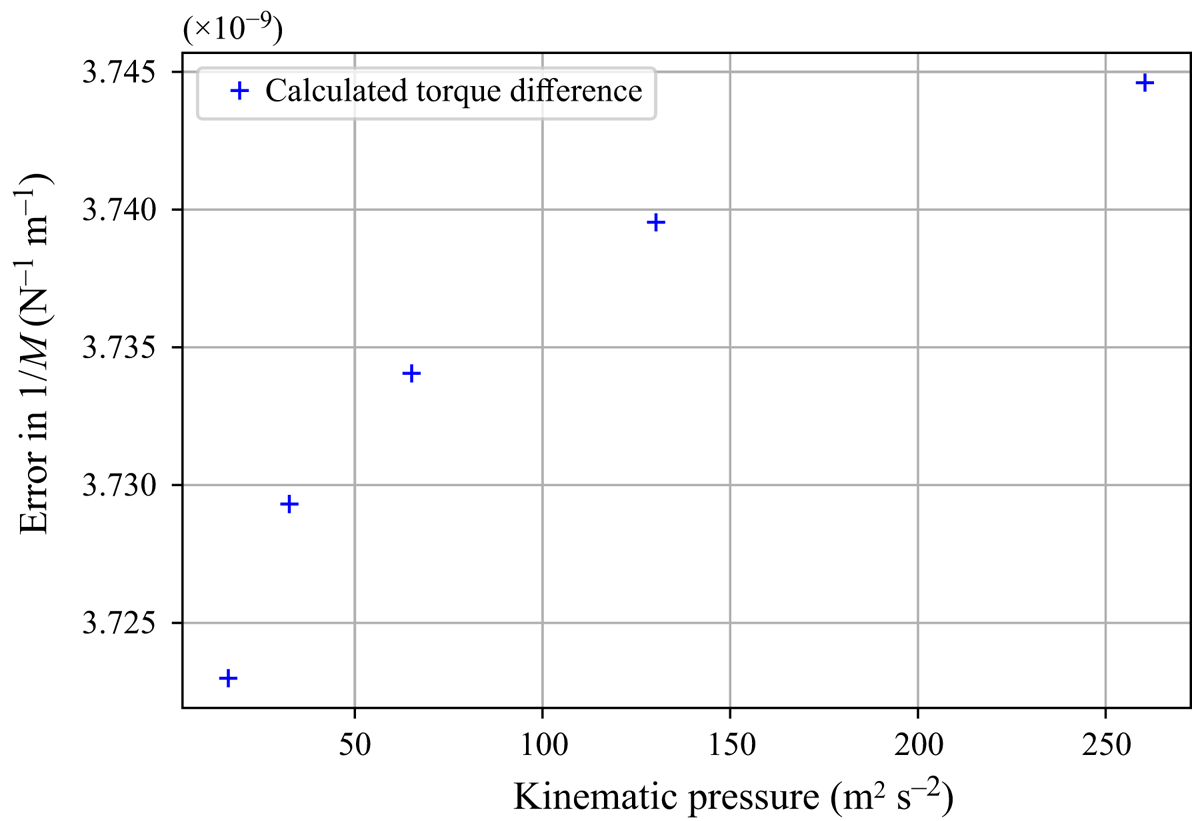
The effect of the velocity component  $v_r$ in the radial direction on the torque $M$ is also investigated. Figure 9 shows the difference in $v_r$ obtained from actual and simplified simulation models at the outlet for an increase of the inlet pressure $p_i$. The behaviour of $v_r$ and $v_\phi$ shows that the simplified simulation model is a good approximation of the actual model. Figure 10 shows that the calculated torque is independent of the inlet flow pressure and, consequently, the radial velocity component.
Error in the radial velocity component at the outlet for an increase in the inlet pressure  $p_i$, obtained from the actual and simplified simulation models.
Difference of reciprocal of the calculated torque  $M$, using the actual and simplified models, with varying kinematic pressure at the inlet for gap height $h=5\ \mathrm {\mu }$m.
In this section, we verified the simplified analytical approach, which neglects the inertial effects as well as the feed flow entering and leaving the device during measurement of the torque. We show that the simplified model is sufficient to infer the slip length  $\lambda$ from the experimentally measured torque.
4. Summary
This work verified and validated the simplified analytical model underlying the measurement principle of the SLT. The SLT is a classical plate tribometer developed to measure the effect of surface roughness in the form of slip length of the Navier-slip boundary condition. The simulation results show very good agreement between the experimental measurements, the analytical model and the simulation models, justifying the use of the simplified analytical model as the basis of the measurement principle of the SLT, which does not take into account the inlet and outlet boundary conditions as well as inertial effects.
Funding statement
We acknowledge financial support by the German Research Foundation (DFG) within the Collaborative Research Centre 1194 (Project-ID 265191195).
Declaration of interests
The authors declare no conflict of interest.
Author contributions
Conceptualization, T.M., M.F. and M.M.G.K.; methodology, H.B.G., T.M., M.F. and M.H.A.; software, M.H.A., H.B.G. and S.R.; validation, M.H.A., H.B.G. and M.M.G.K.; investigation, T.M., M.F. and H.B.G.; writing – original draft preparation, H.B.G. and M.H.A; writing – review and editing, M.F., T.M., M.M.G.K. and D.B; visualization, M.H.A., H.B.G. and S.R.; supervision, T.M., D.B. and P.F.P. All authors have read and agreed to the published version of the manuscript.
Data availability statement
The input data of the simulation set-up are publicly available, as well as the post-processing scripts and the secondary data (Reference Pelz, Corneli, Mehrnia and KuhrPelz et al. 2023; Reference Asghar, Marić, Ben Gozlen, Raju, Fricke, Kuhr, Pelz and BotheAsghar et al. 2024).
Ethical standards
The research meets all ethical guidelines, including adherence to the legal requirements of the study country.


 Open access