

1. Introduction
The proton-boron aneutronic reaction (p + 11B⟶a + 8
 ⟶3a + 8.7 MeV) [Reference Oliphant and Rutherford1, Reference Dee and Gilbert2] has the largest cross section σ ≈ 1.2 b as compared to other neutron-less reactions at the nuclei relative motion energy of about 675 keV [Reference Atzeni and Meyer-ter Vehn3]. The proton-boron (pB) reaction cross section is smaller and the energy when it occurs is much larger in comparison with the same values for the reaction between deuterium and tritium −6 b and 60 keV. For this reason, the energetically profitable pB reaction requires significantly more extreme plasma states than for the fusion between hydrogen isotopes on the base of traditional schemes with magnetic or inertial confinement [Reference Teller4–Reference Sharkov6]. In the long term, advanced proton-boron fuel is very promising, like related almost aneutronic “clean” energy [Reference Moreau7–Reference Hora, Eliezer and Kirchhoff9]. To date, the pB reaction and effects related have proved to be in demand in medicine [Reference Cirrone, Manti and Margarone10, Reference Qaim, Spahn, Scholten and Neumaier11]. The laser initiation of the pB reaction has been demonstrated at the beginning of this century [Reference Belyaev, Matafonov and Vinogradov12]. In recent years, great progress was achieved in laser-driven pB fusion experiments and the growth of α particles yield (sf [Reference Labaune, Baccou and Depierreux13–Reference Margarone, Bonvalet and Giuffrida19] and ref. therein). At the same time, another approach like plasma confinement under extreme conditions in a single device for pB fusion without any external influences is also still of great interest [Reference Kurilenkov, Oginov, Tarakanov, Gus’kov and Samoylov20]. Overall, the inertial electrostatic confinement (IEC) [Reference Elmore, Tuck and Watson21–Reference Dolan28] is one of the very few in which ions can quite easily reach the energies required for the beginning of the pB reaction.
Earlier, on the basis of IEC, an oscillating plasma was proposed as a possible thermonuclear fusion scheme [Reference Nebel and Barnes29, Reference Barnes and Nebel30]. The confinement and acceleration of ions in the IEC scheme take place in the field of a virtual cathode (VC), i.e., in a deep electrostatic potential well (PW) [Reference Elmore, Tuck and Watson21]. However, the “beam”-like ion energy distribution is essentially eroded by Coulomb collisions before the synthesis is substantially realized in traditional IEC schemes [Reference Miley and Murali22]. This problem could be avoided if the ionic component of the plasma would be in the local thermodynamic equilibrium (LTE) state, as suggested in [Reference Nebel and Barnes29, Reference Barnes and Nebel30]. In this scheme, the head-on ion collisions are replaced by the periodically oscillating plasma spheres (POPSs) in the harmonic oscillator potential arranged due to a homogeneous electronic background. At the moment of compression, the high plasma densities and temperatures necessary for nuclear fusion could be achieved. In the process of oscillations, the ions in the POPS scheme have to be in the LTE [Reference Nebel and Barnes29, Reference Barnes and Nebel30]. An important advantage of the POPS-based device is the obtained scaling of the fusion power, which increases with the inverse of the VC radius [Reference Nebel and Barnes29, Reference Park, Nebel, Stange and Murali31]. This feature could reduce in size and cost of each subsequent device of this type [Reference Park, Nebel, Stange and Murali31, Reference Park, Nebel, Stange and Murali32]. Looking forward, if breakeven could be achieved on one small POPS module, this could lead to the creation of a multimodule plant for energy production in the future [Reference Nebel and Barnes29, Reference Park, Nebel, Stange and Murali31, Reference Park, Nebel, Aragonez, Kostora and Evstatiev33]. Initially, it was assumed that POPS plasma is essentially non-neutral, and there would be enough electrons so that the volume charge would neutralize the plasma sphere at the moments of its collapse [Reference Nebel and Barnes29, Reference Barnes and Nebel30]. Afterwards, it was shown that there are important limitations on the compression ratio that could be achieved in the original POPS scheme while maintaining the parabolic potential background and the neutralization of the spatial charge [Reference Evstatiev, Nebel, Chacon, Park and Lapenta34]. As a result, despite the potentially high efficiency of fusion of the POPS in theory [Reference Nebel and Barnes29, Reference Barnes and Nebel30] and demonstration of the POPS in the initial experiment [Reference Park, Nebel, Stange and Murali31, Reference Park, Nebel, Stange and Murali32], in further work, it was not possible to implement the original POPS scheme in nuclear fusion experiments [Reference Miley and Murali22, Reference Evstatiev, Nebel, Chacon, Park and Lapenta34].
The study and development of compact IEC devices with ion oscillations is stimulated, in particular, by favorable scaling of fusion power derived for POPS [Reference Nebel and Barnes29, Reference Barnes and Nebel30], which invites towards the miniaturization of devices. An IEC scheme with reverse polarity [Reference Elmore, Tuck and Watson21] based on a miniature nanosecond vacuum discharge (NVD) [Reference Kurilenkov, Skowronek and Dufty35–Reference Kurilenkov, Tarakanov and Gus’kov37], in which ion oscillations occur quite naturally [Reference Kurilenkov, Tarakanov, Gus’kov, Karpukhin and Valyano38], has a direct relation to this. The NVD experiments and related PiC simulations began at the turn of the century, and over time, it became clear that some hopes associated with the potential advantages of nuclear fusion in the POPS scheme can be realized partially in a miniature NVD [Reference Kurilenkov, Tarakanov, Gus’kov, Karpukhin and Valyano38–Reference Kurilenkov, Tarakanov, Gus’kov, Oginov and Karpukhin41]. The yield of DD neutrons was observed previously and studied in detail in this device [Reference Kurilenkov, Skowronek and Dufty35–Reference Kurilenkov, Tarakanov, Gus’kov, Oginov and Karpukhin41], and an aneutronic proton-boron synthesis was demonstrated also recently [Reference Kurilenkov, Oginov, Tarakanov, Gus’kov and Samoylov20]. Interestingly, the field of the virtual cathode confines the oscillating ions in the NVD, and at the same time, the inertia of the oscillating ions partially holds the electrons of VC by electric fields. So we have called this type of confinement an electrodynamic or oscillatory one (OSCO) [Reference Kurilenkov, Oginov, Tarakanov, Gus’kov and Samoylov20, Reference Kurilenkov, Tarakanov, Gus’kov, Oginov and Karpukhin41].
This paper discusses and compares the features and capabilities of oscillating plasmas for nuclear fusion both in the POPS scheme [Reference Nebel and Barnes29, Reference Park, Nebel, Stange and Murali31, Reference Evstatiev, Nebel, Chacon, Park and Lapenta34] and the OSCO regime based on NVD [Reference Kurilenkov, Oginov, Tarakanov, Gus’kov and Samoylov20, Reference Kurilenkov, Skowronek and Dufty35–Reference Kurilenkov, Tarakanov, Gus’kov, Oginov and Karpukhin41]. The study of a fundamental issue for IEC devices with electron injection as neutralization of the spatial charge started for NVD recently [Reference Kurilenkov, Tarakanov, Oginov, Gus’kov and Samoylov42] and is developing further. Some prehistory and specifics of DD and pB nuclear synthesis study based on NVD are given in Section Reference Dee and Gilbert2. The degree of quasineutrality of proton-boron plasma in the OSCO scheme is investigated numerically in Section Reference Atzeni and Meyer-ter Vehn3. An improved scaling of the DD fusion power has been determined for OSCO and compared with POPS in Section Reference Teller4, and the energy distribution functions of protons and boron ions under pB fusion in the OSCO scheme, which are qualitatively different from the Maxwellian ones in the POPS scheme, are presented also. Section Reference Hogan5 discusses the evolution of the IEC reverse polarity scheme over the past half century and draws some conclusions for the future.
2. On DD and pB Nuclear Synthesis in Miniature Nanosecond Vacuum Discharge (NVD)
Experiments on X-ray generation and DD synthesis in NVD were started at the end of the last century [Reference Kurilenkov, Skowronek, Louvet, Rukhadze and Dufty43], and both single and pulsating yields of DD neutrons were soon registered [Reference Kurilenkov, Skowronek and Dufty35, Reference Kurilenkov and Skowronek44]. However, for some time, the nature of DD neutrons was still unclear. Just subsequent 2D PiC modeling of the processes leading to DD synthesis in NVD [Reference Kurilenkov, Tarakanov, Skowronek, Guskov and Dufty36], based on the full electrodynamic code KARAT [Reference Tarakanov45] revealed the fundamental role of the formation of a virtual cathode (VC) and its corresponding deep potential well (PW) [Reference Kurilenkov, Tarakanov and Gus’kov37, Reference Kurilenkov, Tarakanov, Gus’kov, Karpukhin and Valyano38], which accelerates and confines deuterons. In fact, the OSCO is based on an IEC scheme with reverse polarity [Reference Kurilenkov, Oginov, Tarakanov, Gus’kov and Samoylov20, Reference Elmore, Tuck and Watson21, Reference Kurilenkov, Tarakanov, Skowronek, Guskov and Dufty36, Reference Kurilenkov, Tarakanov and Gus’kov37] and makes it possible to operate in a vacuum, where beams of auto-electrons from the cathode will be formed when the high voltage is applied. The auto-electrons, interacting with the deuterium-loaded Pd anode tubes, at first, will create erosive plasma [Reference Kurilenkov, Tarakanov, Gus’kov, Karpukhin and Valyano38, Reference Varaksin46] near the anode with deuterons and deuterium-containing clusters. Secondly, the electron beams, while flying into the anode space (through the “mesh” of thin Pd tubes) are slowing down as they approach the discharge axis, and then change the direction of movement, thereby forming a VC and the PW corresponding thereto. Thus, the OSCO scheme based on miniature NVD, unlike the rather complex POPS experiment, includes the natural injection of auto-electrons into the anode space, the formation of a very small VC with a radius of r VC∼0.1 cm, and a corresponding PW with a depth of φ PW∼50–100 kV [Reference Kurilenkov, Oginov, Tarakanov, Gus’kov and Samoylov20, Reference Kurilenkov, Tarakanov, Gus’kov, Oginov and Karpukhin41]. Head-on collisions of deuterons accelerated in PW up to ∼100 keV are accompanied by the release of DD neutrons. Deuterons can oscillate in the PW, and at the moments of their collapses at the PW bottom, the main DD synthesis takes place [Reference Kurilenkov, Tarakanov, Gus’kov, Karpukhin and Valyano38]. As a result, periodic oscillations of deuterons in PW are leading to the pulsating output of DD neutrons [Reference Kurilenkov, Skowronek and Dufty35, Reference Kurilenkov, Tarakanov, Gus’kov, Oginov and Karpukhin41, Reference Kurilenkov, Tarakanov, Gus’kov, Oginov and Samoylov47]. At the same time, the PW permanently holds the oscillating deuterons, since the energy they gain in the VC field is always insufficient to leave the well.
Earlier, in the POPS scheme, the scaling of the oscillation frequency f POPS by the ion mass and the depth of the potential well was obtained [Reference Park, Nebel, Stange and Murali31, Reference Park, Nebel, Stange and Murali32]. There was a good agreement between the observed resonant frequency for some test ions [Reference Park, Nebel, Stange and Murali31] and theoretical predictions for f POPS ≈ (2e φ PW/r 2 VC m i)1/2/2π [Reference Park, Nebel, Stange and Murali32] (m i -deuteron mass and e-electrostatic charge). In a more general case, a similar dependence of the ion oscillation frequency can be estimated from the inverse time of the ion flight by the radius of anode space to the discharge axis (Figure 1(a)) and back f OSC∼u i /r VC, where u i ≈ (Ze φ PW/2m i )1/2-the average velocity of an ion with a charge Z. Remarkably, the theoretical POPS scheme has some analogue of the oscillating deuterons in NVD which are manifesting through pulsating neutron yield observed [Reference Kurilenkov, Skowronek and Dufty35, Reference Kurilenkov, Tarakanov, Gus’kov, Oginov and Karpukhin41]. In fact, at the NVD experiment with deuterated Pd anode we have PW depth φ ≈ 50–60 kV, namely, for deuterons (φ PW is about 80% of the voltage applied), and the frequency of pulsating neutron yield registered comes to about ≈80 MHz [Reference Kurilenkov, Skowronek and Dufty35, Reference Kurilenkov, Tarakanov, Skowronek, Guskov and Dufty36, Reference Kurilenkov, Tarakanov, Gus’kov, Oginov and Samoylov47]. A close value can be evaluated by extrapolation of expressions f POPS or f OSC presented above to the parameters of the NVD experiment and A-C geometry. Further definite similarities and differences of the POPS physics and some oscillating ions regimes at nanosecond vacuum discharge are discussed in Section Reference Teller4.
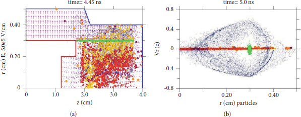
(a) Geometry of electrodes in nanosecond vacuum discharge (NVD) under PiC simulations of pB syntheses for U = 100 kV and front ∆t
f
= 1 ns (anode-red, cathode-blue, and green area-“anode plasma” with protons and boron ions). Electrons (blue dots), protons (red), and boron ions (Z
B
= +3, yellow), and residues of pB reaction products are shown in the anode space at the simulation moment t = 4.45 ns (circles of larger diameter, gray: 8
 , purple: primary α particles, dark orange: secondary α particles [Reference Kurilenkov, Oginov, Tarakanov, Gus’kov and Samoylov20]. (b) The velocity of electrons on radius, Vr/c < 0, accelerated to an energy of ≈100 keV when passing in simulations through “the anode Pd tubes” (green area) at t = 5 ns (c–velocity of light). The electrons are inhibited in the anode space close to the discharge axis, form a virtual cathode, r
VC ≈ 0.1 cm and are reflected further (Vr/c > 0) by oncoming electron flows in the opposite direction (VC along axis Z is also visible in Figure 1(a)). Protons, boron ions, and pB reaction products are represented partially here also in the vicinity of Vr/c ≈ 0.
, purple: primary α particles, dark orange: secondary α particles [Reference Kurilenkov, Oginov, Tarakanov, Gus’kov and Samoylov20]. (b) The velocity of electrons on radius, Vr/c < 0, accelerated to an energy of ≈100 keV when passing in simulations through “the anode Pd tubes” (green area) at t = 5 ns (c–velocity of light). The electrons are inhibited in the anode space close to the discharge axis, form a virtual cathode, r
VC ≈ 0.1 cm and are reflected further (Vr/c > 0) by oncoming electron flows in the opposite direction (VC along axis Z is also visible in Figure 1(a)). Protons, boron ions, and pB reaction products are represented partially here also in the vicinity of Vr/c ≈ 0.

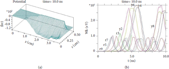
(a) The field of virtual cathode (or potential well) for U = 100 kV with a front ∆t f = 1 ns and (b) the energy of the isolated groups of boron ions (Z B = +3, index (y)) and protons (index (r)) during their oscillations in the potential well on time (for U exp ≈ 100 kV with ∆t f ≈ 2 ns).

It should be noted the great progress made in recent years in the study of laser-driven pB fusion and increasing α particles yields in the experiments related [Reference Labaune, Baccou and Depierreux13–Reference Margarone, Bonvalet and Giuffrida19]. In addition to laser-driven fusion schemes, the implementation of pB fusion in one very compact device without the external influence of lasers or proton beams is also of fundamental and applied interest. In general, the scenario of DD synthesis in NVD with a virtual cathode remains valid for the pB reaction. By analogy with DD synthesis, PiC simulation showed that the proton-boron aneutronic reaction can also be achieved by accelerating and confining protons and boron ions by the field of the virtual cathode in NVD [Reference Kurilenkov, Tarakanov and Gus’kov48]. In the process of their oscillations in PW, head-on collisions of a part of protons and boron ions with energies of ∼100–500 keV lead to a proton-boron reaction. The specifics of an OSCO at pB syntheses are that the oscillations periods of boron ions and protons are different due to the difference in their masses and charges. Nevertheless, under certain conditions, which are realized both in PiC simulations [Reference Kurilenkov, Tarakanov and Gus’kov48, Reference Kurilenkov, Tarakanov, Gus’ kov, Samoylov and Ostashev49] and in the testing experiments [Reference Kurilenkov, Oginov, Tarakanov, Gus’kov and Samoylov20], these ions and protons can collide in the vicinity of the discharge axis and with a certain probability reaction pB takes place. The results of the first experiments on the pB fusion in miniature NVD with plasma oscillatory confinement were presented recently [Reference Kurilenkov, Oginov, Tarakanov, Gus’kov and Samoylov20]. The device is based on a low energy (≈1 J) NVD with a virtual cathode also. The field of VC accelerates protons and boron ions to the energy thresholds required for notable pB synthesis under the collapse of ions in the vicinity of the PW “bottom.” On average, the yield of α particles registered was about 250 α particles per one shot (≈1 J, voltage pulse U ≈ 100 kV, duration τ ≈ 20 ns) in a given series of demonstration experiments [Reference Kurilenkov, Oginov, Tarakanov, Gus’kov and Samoylov20]. As noted [Reference Kurilenkov, Oginov, Tarakanov, Gus’kov and Samoylov20], the geometry of the old Pd anode used earlier in DD synthesis was suboptimal, but it was very convenient for filling with boron nanoparticles due to the developed surface microrelief (Figure 3 in [Reference Kurilenkov, Oginov, Tarakanov, Gus’kov and Samoylov20]). For the case of a larger number of well-defined oscillations of ions in a better geometry of electrodes (Figures 1(a) and 2(b)), we have to obtain at least ∼103/4π α particles per one J. This is still significantly less than what is observed in the modern laser-driven pB fusion experiments (where the yield of α particles can reach ∼107 sr/J, from the outlet [Reference Giuffrida, Belloni and Margarone16, Reference Margarone, Bonvalet and Giuffrida19]), but obtaining in a single miniature device without external influence of lasers or proton beams [Reference Kurilenkov, Oginov, Tarakanov, Gus’kov and Samoylov20].
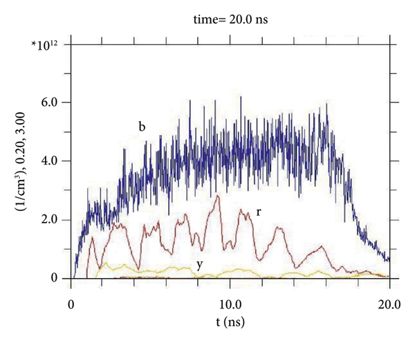
Density of electrons (b), protons (r), and boron ions (y) (with a charge of Z B = +3) on time at the selected point by radius r = 0.2 cm of the anode space and the axis point Z = 3 cm Figure 1(a) for U exp ≈ 100 kV with a front ∆t f ≈ 2 ns.

Let us note that the energies of protons (≤100 keV) and boron ions (≤500 keV) in the NVD are relatively small, for example, in comparison with those in the laser-driven proton-boron fusion [Reference Giuffrida, Belloni and Margarone16]. As a result, the efficiency Q = E output/E input in the first experiments on pB synthesis in a single miniature device for proton-boron plasma confinement also is still very low ∼10−9. If the voltage is increased to U = 150 kV or higher, we can get closer to the main resonance peak of the pB reaction at 675 keV. Looking forward to an α particles source based on NVD, if we use a pulse periodic high voltage generator and solve the problem of heat dissipation, the α particles yield in NVD will be proportional to the frequency of the voltage applied, for example, at ∼100 kHz it would be about 108 α particles/s. Again, it is not so much as for laser-drivenα particles sources, but a practical niche as a simple and cheap compact α particle source is not excluded. Last but not least, further studies are to show the prospects for the creation of a practical miniature reactor for pB synthesis based on oscillatory confinement in NVD. In the very long term, if reasonable values Q > 1 would be achieved in a single miniature device (Chapter 13 in [Reference Miley and Murali22]), the possible route for energy production could be associated with a multimodule (∼107) arrays for a power plant which were suggested for fusion in a POPS scheme [Reference Park, Nebel, Stange and Murali31, Reference Park, Nebel, Aragonez, Kostora and Evstatiev33].
3. Space Charge Neutralization and Degree of Quasineutrality in NVD
Neutralization of the space charge is an important issue under electron injection in devices like IEC [Reference Miley and Murali22, Reference Nebel and Barnes29, Reference Park, Nebel, Stange and Murali31]. In this section, we will consider the degree of plasma quasineutrality in the OSCO scheme at cylindrical geometry using the example of PiC modeling of pB synthesis. As earlier [Reference Kurilenkov, Oginov, Tarakanov, Gus’kov and Samoylov20, Reference Kurilenkov, Tarakanov and Gus’kov48], we will also use the code KARAT [Reference Tarakanov45] for this purpose. It is a versatile FDTD relativistic, fully electromagnetic code based on the PIC method. The code is designed to solve nonstationary problems of electrodynamics having complex geometry and including plasma, electron, and ion beams. For current research [Reference Kurilenkov, Oginov, Tarakanov, Gus’kov and Samoylov20], modeling of binary interaction has been added. It is based on PiC simulation of particle collisions and the subsequent generation of secondary particles with a probability corresponding to the velocity of the primary particles and theoretical or experimental cross-section. When modeling the processes leading to the synthesis of pB in NVD, we will derive the concentrations of all charged particles at different parts of the anode space (Figure 1(a)) on time. It will allow estimating the degree of plasma quasineutrality in anode space by radius. The 2D PiC simulations presented below were carried out for two cases: at the voltage applied of U = 100 kV with a voltage front ∆t f = 1 ns, and for the experimental values U exp ≈ 100 kV, ∆t f ≈ 2 ns used for demonstration of the pB fusion in NVD [Reference Kurilenkov, Oginov, Tarakanov, Gus’kov and Samoylov20] (VA characteristics of the voltage pulse-periodical generator are given in Figure 2(b) in [Reference Kurilenkov, Oginov, Tarakanov, Gus’kov and Samoylov20]). There were 50 grid points by radius r and 300 ones by Z axis under PiC simulations. The total number of macro particles was up to 106.
In Figure 1(a) the cylindrical geometry of the electrodes is shown, with the anode-cathode (A-C) space 0.1 cm. In 2D simulations, a thin anode “plateau” inside the cathode corresponds to the real anode from cylindrical Pd tubes attached to the end of the anode along its perimeter [Reference Kurilenkov, Tarakanov, Gus’kov, Karpukhin and Valyano38]. On the left, a TEM wave from a high-voltage generator is launched into the coaxial along the axis Z.
In Figure 1(a), it shows the creation of an electric field between anode and cathode, providing auto-electronic emission. In this field, the electrons are accelerated by radius to the discharge center (blue dots are shown in the figures), and cross the anode (green area at r ≈ 0.3 cm) with an energy of ≈100 keV (Vr/c < 0, Figure 1(b)). Irradiation of the anode by electron beams produces the “emission” of boron ions and protons. Penetrating further into the anode space, electrons are inhibited and reflected by oncoming flows and form a VC with a radius of ≈ 0.1 cm in a result (Figure 1; [Reference Kurilenkov, Oginov, Tarakanov, Gus’kov and Samoylov20] for details and PiC simulations movie). Inside the anode the external pulse electric field is absent; however, the negative electric charge of electrons creates PW in the vicinity of the axis. It provides acceleration of protons and boron ions along the radius to the discharge axis Z (r = 0). Here, the latter’s velocity reaches its maximum value, as well as its density.
The potential well corresponding to the VC of the electron cloud inside the anode space is presented in Figure 2(a) (at the 10th ns of simulation). The PW depth is about ≈100 kV. In the pB fusion experiment, the anode Pd tubes were filled with hydrogen, and a tube surface with a microrelief developed is covered by boron nanoparticles [Reference Kurilenkov, Oginov, Tarakanov, Gus’kov and Samoylov20]. The protons and boron ions will appear at the edge of the PW under irradiating Pd anode tubes by energetic electrons. In PiC modeling, the anode “tube” (Figure 1(a)) was also “fulfilled” by protons and boron ions (with a charge just of +3). Radial acceleration of protons and boron ions in the field of VC were followed by their oscillations in the deep PW, which will confine them also during oscillations.
The specifics of OSCO are illustrated in Figure 2(b), where the energies of randomly chosen isolated groups of protons (index r) and boron ions (index y) in PW on time are given. For this purpose, at five Z coordinates (in the range of 2-3 cm), the locations of protons and boron ions were randomly selected at r = 0.3 cm (distance to the anode, Figure 1(a)). The particles closest to these points were selected from the cloud of “anode plasma” at the initial moment of time. Furthermore, the histories of all particle parameters (coordinates, velocities, and energies) in time, as well as the electric fields acting on them, were traced. PiC modeling recognizes the oscillatory nature of confinement of protons and boron ions in PW; in fact, the maximum energy of the charges corresponds to the moment when they are passing through the discharge axis, and a minimum of kinetic energy corresponds to the full deceleration of ions in PW and a downward turn at its upper edge. Note that, fast boron ions appear for the voltage front ∆t f ≈ 2 ns only in the time interval 4-5 ns (Figure 2(b)), while for the voltage front ∆t f = 1 ns they will appear already at 2-3 ns (not shown here), and also earlier than for ∆t f ≈ 2 ns the first α particles will appear here (Section 4). For a voltage front ∆t f = 5 ns, fast boron ions and α particles will appear as in the first case at interval 4-5 ns (the results of 2D PiC simulations for the case of slower voltage rise ∆t f = 5 are presented in [Reference Kurilenkov, Tarakanov, Oginov, Gus’kov and Samoylov42]).
The frequencies of oscillation for protons and boron ions are different (Figure 2(b)) since there is a difference in mass and charge (Section 2). This circumstance does not contribute properly to the efficiency of synthesis. Nevertheless, head-on collisions of protons and boron ions at the discharge axis and in its vicinity with sufficient energies lead to a pB reaction, and related α particles were registered in the first pB fusion NVD experiments [Reference Kurilenkov, Oginov, Tarakanov, Gus’kov and Samoylov20]. Thus, Figures 1 and 2 illustrate the key role of formation VC and the deep PW related in the sequence of the main events leading to pB fusion in NVD.
Earlier, for the POPS model, there was a question on the amount of compression that can be achieved by oscillating plasmas while simultaneously maintaining parabolic background potential and space charge neutralization [Reference Park, Nebel, Stange and Murali31, Reference Evstatiev, Nebel, Chacon, Park and Lapenta34]. Let us proceed to the analysis of the latter and the degree of quasineutrality of the pB plasma in the OSCO regime in NVD. For illustration, the rather typical concentration ratio of all charges at selected point r = 0.2 cm of the anode space on time is given in Figure 3. We see that, in general, the number of electrons slightly exceeds the total number of ions (curves in Figure 3 are calculated by the average over an area of ±0.05 cm adjacent to the chosen point r = 0.2 cm). The concentration of protons fluctuates periodically on the electronic background, which corresponds to the arrival of protons in this area; meanwhile, the density of boron ions represents at this area of anode space something like a positively charged plateau. Underline, the concentration ratio of ions and electrons presented in NVD under simulations even far from the discharge axis (Figure 3) is different qualitatively and quantitatively from the ratio n i /n e ∼ 0.1 accepted widely under the study and analysis of the POPS fusion scheme [Reference Nebel and Barnes29–Reference Park, Nebel, Aragonez, Kostora and Evstatiev33].
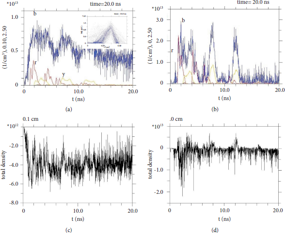
Let us consider in more detail the range which is closer to discharge axis under the short voltage front ∆t f = 1 ns. Figures 4(a) and 4(b) show the concentrations of electrons, protons, and boron ions on time for two fixed points r = 0.0 cm and 0.1 cm by discharge radius at chosen Z = 2.5 cm on the discharge axis. The data in Figure 4(a) corresponds to a point r = 0.1 cm which is rather close to the axis (Figure 1(a)). The electron density is given by curve b, and curves r and y represent the densities of protons and boron ions, respectively. The first protons are coming to this area at t ≈ 2 ns, and boron ions are appearing later due to the larger mass. We see that there are more electrons than ions in the entire time interval presented since r ≈ r VC ≈ 0.1 cm. Meanwhile, on the axis of discharge (Figure 4(b), r = 0.0 cm), where n e is several times higher than for the case of r = 0.1 cm, the electron density curve practically corresponds in magnitude to the total density of protons and boron ions (the latter have to be multiplied by their charge Z b = +3) on time. Let us introduce the function μ(t) = −n e (t) + n p (t) + Z B n B (t) for a qualitative assessment of the degree of quasineutrality using the obtained graphs of electrons and ions concentrations (Figures 4(a) and 4(d)). Functions μ(t) are shown for both cases at Figure 4(c) (r = 0.1 cm) and Figure 4(d) (r = 0.0 cm), correspondingly. So we see that the plasma in the close vicinity of the discharge axis is almost a quasineutral one n i (t) ≈ n e (t) not only at individual moments of time but also during almost the entire time of simulation t = 20 ns (Figure 4(d)). Similar quasineutrality is available also for slower voltage rise ∆t f = 5 ns [Reference Kurilenkov, Tarakanov, Oginov, Gus’kov and Samoylov42]. Remark, in the region of the anode space r ≈ 0.1 cm, electrons, decelerating and unfolding, form a VC with a large electron density (Figure 1), and the deviation from quasineutrality there naturally should be maximal (Figure 4(c)).
Concentrations of charges at selected points of the anode space on time at Z = 2.5 cm (PiC simulations for an applied voltage U = 100 kV with a front ∆t f = 1 ns): (a) r = 0.1 cm and (b) r = 0.0 cm. The blue curves are electrons (b), the red ones are protons (r), and the yellow ones are boron ions (y) with a charge of Z B = +3. The related values of total density of charges, or function μ(t) = −n e (t) + n p (t) + Z B n B (t), are given at (c) and (d) for radial points r = 0.1 cm and r = 0.0 cm, correspondingly (see text). The energy of electrons as a function of their position along the discharge radius is shown in the Figure 4(a) inset (r VC ≈ 0.1 cm, see Figure 1(a) also).

At t > 15 ns, the “fuel” for pB nuclear fusion embedded in the “anode plasma” (Figure 1(a)) under simulation runs out (Figure 4).
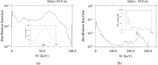
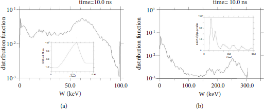
Energy distribution functions in NVD for (a) protons and (b) boron ions with charge Z B = +3 for U exp ≈ 100 kV with a front ∆t f ≈ 2 ns. The potential along the radius is shown at the inset in Figure 5(a) for t = 10 ns (it is cross section at Z = 2.5 cm for the PW presented in Figure 2(a)). The output of secondary α particles from pB reaction on time for U = 100 kV and ∆t f = 1 ns (see Figure 4(b) also) is shown at the inset in Figure 5(b).
To describe the degree of quasineutrality of the plasma, by analogy with [Reference Evstatiev, Nebel, Chacon, Park and Lapenta34], we introduce the parameter η = n i0/n e0, where n i0 is the initial ion density, n e0 = n e –n i is the electron density which is forming a virtual cathode of homogeneous density (n e and n i are concentrations of electrons and ions, respectively, depending generally on coordinates and time). In a quasineutral limit, we have n e0⟶0 and get η⟶∞ formally [Reference Evstatiev, Nebel, Chacon, Park and Lapenta34]. Based on the simulations presented above, we may conclude that in a certain area around the axis of discharge (r = 0 cm) during the oscillations of ions in PW, the parameter of quasineutrality η can reach the local values of the order of 10–100 (after the first 3-4 ns, function μ(t) ≈ 0 fluctuates around zero, and almost does not change over time, as shown in Figure 4(d)).
4. Small-Scale Oscillations at the Quasineutral Limit in Vacuum Discharge. The Advantages and Limitations of a POPS Fusion Scheme
The advanced concept of POPS [Reference Nebel and Barnes29–Reference Park, Nebel, Aragonez, Kostora and Evstatiev33] gave a new strong pulse to the study of the IEC scheme with reverse polarity, especially in theory. It was shown that the total power of thermonuclear fusion in POPS is scaled as P∼φ PW 2 η 2 θ 2/r VC, where η ≈ n i /n e ∼0.1, r VC∼a-anode space radius, and θ is the compression ratio [Reference Nebel and Barnes29, Reference Park, Nebel, Stange and Murali31] (in the original POPS scheme, the value θ should be ∼103). Thus, a critical advantage for a POPS-like device for fusion is favorable fusion power scaling, which increases with the inverse of VC radius [Reference Nebel and Barnes29]. Each next POPS device generation has to be more efficient and smaller compared to the previous one [Reference Park, Nebel, Stange and Murali31], and it also might lead to a modular and high mass power density economical device (see Table I in [Reference Park, Nebel, Stange and Murali31] for potential applications of POPS fusion devices). Looking forward, it was remarked also that a multimodule power plant or advanced space propulsion [Reference Park, Nebel, Stange and Murali31, Reference Park, Nebel, Aragonez, Kostora and Evstatiev33] could be considered if breakeven would be achieved.
Furthermore, the POPS scheme was demonstrated experimentally for H2 +, He+ и Ne+ ions for IEC with grids [Reference Park, Nebel, Stange and Murali31], where the ions exhibit resonant behavior in the field of VC when moving at the frequencies of POPS. The scaling of the oscillation frequency f POPS by the ion mass and the depth of the potential well was obtained, and it was in good agreement with the predictions of the theory [Reference Park, Nebel, Stange and Murali32]. The PW depths estimated for the experiment did not exceed 300 V, and the ion oscillation frequencies did not exceed 700 kHz. Thus, the values of the applied voltage U were rather small there, and so far it was not about DD nuclear fusion. Nevertheless, the experiment on the demonstration of POPS was successful [Reference Park, Nebel, Stange and Murali31–Reference Park, Nebel, Aragonez, Kostora and Evstatiev33], but some factors such as a separate injection of electrons and setting external resonant pulses with a frequency of POPS made it quite complicated. Besides, a subsequent more detailed analysis by the authors of the POPS have shown [Reference Evstatiev, Nebel, Chacon, Park and Lapenta34] that there are some critical limitations on the degree of compression that can be achieved by an oscillating plasma while maintaining the neutralization of the spatial charge and the parabolic background potential. These conditions make operation in the POPS regime impractical [Reference Evstatiev, Nebel, Chacon, Park and Lapenta34].
At the same time, the work [Reference Evstatiev, Nebel, Chacon, Park and Lapenta34] has also suggested the use of small compressions as another option in the quasineutral limit η⟶∞ [Reference Evstatiev, Nebel, Chacon, Park and Lapenta34]. It was noted that this leads to a device different from the one originally envisioned for POPS. For the new device, POPS-type oscillations are primarily a mechanism of resonant ion heating, rather than coherent compression. Since the compression ratios are small there, a high ion temperature is required when the plasma is expanded [Reference Evstatiev, Nebel, Chacon, Park and Lapenta34]. Unlike the initial scenario with POPS, in these devices, it is possible to work with a mixture of deuterium and tritium also. Note that, a similar device was originally studied theoretically by Elmore et al. [Reference Elmore, Tuck and Watson21]. Apparently, small compressions, very small r VC values, and plasma in the quasineutral limit are options which have been realized in experiments with miniature NVD independently [Reference Kurilenkov, Skowronek and Dufty35, Reference Kurilenkov, Tarakanov, Skowronek, Guskov and Dufty36, Reference Kurilenkov and Skowronek44]. This was preceded namely by a broad experimental search for the possibility of DD synthesis in a miniature NVD scheme [Reference Kurilenkov, Skowronek, Louvet, Rukhadze and Dufty43, Reference Kurilenkov and Skowronek44], partially stimulated at that time by the exciting results on DD fusion from explosions of femtosecond laser-heated deuterium clusters [Reference Ditmire, Zweiback, Yanovsky, Cowan, Hays and Wharton50, Reference Zweiback, Smith and Cowan51].
In fact, oscillatory confinement in NVD also uses small POPS-type oscillations to heat the plasma [Reference Kurilenkov, Oginov, Tarakanov, Gus’kov and Samoylov20, Reference Kurilenkov, Tarakanov, Gus’kov, Oginov and Karpukhin41]. Present PiC simulations (as well as preliminary ones [Reference Kurilenkov, Tarakanov, Oginov, Gus’kov and Samoylov42]) are showing that the oscillating plasma in the NVD near and on the discharge axis represents a rather quasineutral mode (Figure 4(d)), where the value of the parameter η can reach ∼100. Also, we can estimate the compression ratio value as just θ < 10 if comparing charge densities on the discharge axis (Figure 4(b)) and far from the axis (Figure 3). The aneutronic pB synthesis demonstrated recently [Reference Kurilenkov, Oginov, Tarakanov, Gus’kov and Samoylov20], where the working fuel mixture was of different masses, indirectly confirms also [Reference Evstatiev, Nebel, Chacon, Park and Lapenta34] that the plasma regime in NVD is a quasineutral one. Note that, the experiment on DD synthesis in NVD [Reference Kurilenkov, Skowronek and Dufty35, Reference Kurilenkov and Skowronek44] with a small-scale deuteron oscillation (via neutron yield which is pulsating, Figure 4 in [Reference Kurilenkov, Skowronek and Dufty35]) have appeared slightly earlier than small POPS-like oscillations were suggested to heat the plasma (Section 5 in [Reference Evstatiev, Nebel, Chacon, Park and Lapenta34]).
The physics of POPS and small-scale oscillations in NVD are different, nevertheless, favorable scaling of DD fusion power for POPS is also preserved for an OSCO. For the cylindrical geometry of NVD, we can get Р∼φ PW 2 η 2 θ l/π e 2 r 2 VC (l is cylinder length and e is the electron charge). At the same time, the values of the parameters included in the expression for P will themselves vary greatly. For POPS we have η∼0.1 and θ∼103 [Reference Nebel and Barnes29, Reference Park, Nebel, Stange and Murali31], while for an OSCO we get η∼100 and θ ≤ 10 as well as the typical values r VC ∼ 0.1 cm and φ PW∼100 kV, which are necessary especially for high fusion power [Reference Kurilenkov, Tarakanov, Gus’kov, Oginov and Karpukhin41] at miniature NVD.
The α particles yield in time, with the maxima at t ≈ 2.7 ns and at t ≈ 4.2 ns, shown at inset in Figure 5(b) (small maxima can be barely discerned in Figure 4(b) also, near the horizontal axis, where the densities of protons and boron ions are overlapped, and their energies are sufficient for pB synthesis). The energy of the accelerated protons under OSCO is close to the energy of the electrons injecting radially in the NVD scheme, which ensures its certain stability [Reference Elmore, Tuck and Watson21, Reference Evstatiev, Nebel, Chacon, Park and Lapenta34]. However, the ion energy distribution functions remain non-Maxwellian ones [Reference Kurilenkov, Tarakanov, Skowronek, Guskov and Dufty36, Reference Kurilenkov, Tarakanov, Gus’ kov, Samoylov and Ostashev49]. As an illustration, Figure 5 shows the distribution functions (DF) of protons and boron ions obtained in PiC simulations by averaging over the entire anode space (averaging only near the axis leads to a well-defined beam-like DF [Reference Miley and Murali22]). Underline, in the experiments with NVD available today, the ions flight time of the entire anode space volume turns out to be less than the time needed for ion-ion relaxation under ions converging to the discharge center [Reference Gus’kov and Kurilenkov40]. As a result, we do not have the microvolumes of thermonuclear plasma in NVD (such as those predicted earlier [Reference Elmore, Tuck and Watson21] in similar, but spherical geometry), while DD [Reference Kurilenkov, Skowronek and Dufty35–Reference Kurilenkov, Tarakanov, Gus’kov, Oginov and Karpukhin41] and aneutronic pB synthesis [Reference Kurilenkov, Oginov, Tarakanov, Gus’kov and Samoylov20] are observed certainly in the nonequilibrium plasmas (Figure 5) remaining nonignited on the discharge axis [Reference Kurilenkov, Tarakanov, Skowronek, Guskov and Dufty36, Reference Kurilenkov, Tarakanov, Gus’ kov, Samoylov and Ostashev49, Reference Hirsch52] (remark, the role of nanoparticles in the processes of X-ray generation and nuclear synthesis in NVD requires separate consideration, for example, [Reference Kurilenkov, Oginov, Tarakanov, Gus’kov and Samoylov20, Reference Varaksin46, Reference Smetanin, Kurilenkov, Oginov, Tarakanov and Samoylov53, Reference Varaksin54]). At the same time, it should be noted that obtaining the desired type of ion distribution functions between two opposite limits like “beam-Maxwellian” ones [Reference Miley and Murali22] is a challenging but promising future task. In particular, the type of DF and the specifics of the oscillations and confinement of boron ions are affected, for example, by the rate ∆t f in increase of the high voltage applied. In fact, with a slower voltage increase such as ∆t f = 5 ns [Reference Kurilenkov, Tarakanov, Oginov, Gus’kov and Samoylov42], it is possible to obtain a “more Maxwellian” type of DF and a more stable acceleration and confinement of ions during their oscillations in potential well (Figure 2(b) in [Reference Kurilenkov, Tarakanov, Oginov, Gus’kov and Samoylov42]) in comparison with the case ∆t f = 1 ns (not shown here), where the part of boron ions can leave rather deep PW (Figure 2(a)) along the axis Z.
5. Concluding Remarks
The concept of IEC was first suggested to try to solve the problem of controlled fusion by Lavrent’ev in 1950 (see [Reference Miley and Murali22–Reference Bondarenko25, Reference Dolan28] and refs therein). The first theoretical paper on IEC appeared only in 1959 and was devoted to the IEC with reverse polarity [Reference Elmore, Tuck and Watson21]. A device with a nonparabolic potential well has been proposed for the plasma confinement at thermonuclear temperatures. The projection of electrons radially through the surface of a transparent spherical anode was considered. Electrons will be stopped by their mutual repulsion near the center and reflected back, which forms a negative electrostatic potential in the anode interior. Such a PW could ensure the convergence of radial ion flows to the center, where a high ion density can be achieved in the focus itself (we see that this even in detail resembles the physical processes presented in Figures 1 and 2 discussed above for almost parabolic PW at cylindrical geometry). The authors concluded that this scheme is unlikely to be realized as a real thermonuclear reactor, but “it may be suitable for obtaining small volumes of thermonuclear plasma for research” [Reference Elmore, Tuck and Watson21]. Despite the relative simplicity of IEC devices with reverse polarity, their evolution is progressing quite slowly. The advanced IEC scheme with POPS proposed only 40 years later [Reference Nebel and Barnes29, Reference Barnes and Nebel30] has promised in theory the efficiency necessary even for the generation of fusion energy. Unfortunately, it was not possible to move further in the POPS experiments with thermal ions in modified Penning traps [Reference Nebel and Barnes29, Reference Barnes, Schauer, Umstadter, Chacon and Miley55, Reference Barnes56] and realize the predicted favorable scaling of the fusion power [Reference Miley and Murali22, Reference Park, Nebel, Stange and Murali31, Reference Evstatiev, Nebel, Chacon, Park and Lapenta34].
In order to continue the studies of the IEC with reverse polarity, and relying on the PiC simulations using the electromagnetic code [Reference Kurilenkov, Tarakanov, Skowronek, Guskov and Dufty36, Reference Kurilenkov, Tarakanov and Gus’kov37, Reference Kurilenkov, Tarakanov, Gus’kov, Oginov and Karpukhin41], over the past two decades we have been able to implement experimentally both DD synthesis [Reference Kurilenkov, Skowronek and Dufty35, Reference Kurilenkov, Tarakanov, Gus’kov, Karpukhin and Valyano38, Reference Kurilenkov, Tarakanov, Karpukhin, Gus’kov and Oginov39, Reference Kurilenkov, Tarakanov, Gus’kov, Oginov and Karpukhin41, Reference Kurilenkov, Tarakanov, Gus’kov, Oginov and Samoylov47] and aneutronic pB synthesis [Reference Kurilenkov, Oginov, Tarakanov, Gus’kov and Samoylov20, Reference Kurilenkov, Tarakanov and Gus’kov48, Reference Kurilenkov, Tarakanov, Gus’ kov, Samoylov and Ostashev49] in a miniature NVD with oscillatory confinement. The OSCO, like the POPS scheme, has a very advantageous scaling of nuclear fusion power, and, together with a very small VC radius (r VC ∼ 0.1 cm, Figure 1) and deep PW (∼100 kV, Figure 2(a)), it provides high fusion power density in NVD [Reference Kurilenkov, Tarakanov, Gus’kov, Oginov and Karpukhin41, Reference Kurilenkov, Tarakanov, Gus’kov, Oginov and Samoylov47]. As shown by the PiC simulations presented above, the neutralization of the spatial charge is not a problem for an OSCO in cylindrical geometry (Figures 3 and 4), unlike the POPS scheme in the spherical one [Reference Evstatiev, Nebel, Chacon, Park and Lapenta34]. The NVD plasma turns out to be quasineutral in the anode space with an accuracy up to a factor of ∼2, while in the vicinity and on the discharge axis, where pB synthesis is most likely, it is practically a neutral one (the latter is illustrated also by the view of potential well φ PW at r ≤ 0.1 cm, where the field strength ≈ 0, Figure 5(a) inset). Nevertheless, the features of scaling of DD fusion power, and especially the specifics of pB fusion power in NVD under oscillatory confinement discussed above, require further more detailed analysis, including the analogue of Lawson criterion [Reference Miley and Murali22] for pB fusion.
Overall, it is clear also that the key problem for further work is finding ways to improve the efficiency of available an OSCO scheme. At the present stage of the pB fusion experiment [Reference Kurilenkov, Oginov, Tarakanov, Gus’kov and Samoylov20], the optimization of geometry and parameters of the discharge can contribute to this goal, which can move closer in ions energies to the maximum of pB reaction cross-section, provide well-defined ions oscillations in the PW at higher energies, shift the DF view towards the Maxwellian type, etc. Apparently, at the next stage of the work, it will be necessary to add a magnetic field in the experiment to confine better the electrons of the virtual cathode, for example, on the basis of the small-scale Polywell-like [Reference Miley and Murali22, Reference Bussard57, Reference Santarius58] configuration. It might increase VC lifetime which would provide periodical pB synthesis near the discharge axis (Figures 4(b) and 5(b) inset) without additional injection of electrons and get the higher efficiency. Then, the hypothetical breakeven for pB fusion will be achieved by summation of very small gains over the entire periodic very short times of “nonthermonuclear” pB burning during the whole time [Reference Kurilenkov, Tarakanov, Gus’kov, Oginov and Samoylov47] of oscillatory confinement needed to get Q > 1.
Data Availability
The data used to support the findings of this study are included within the article.
Conflicts of Interest
The authors declare that there are no conflicts of interest.
Acknowledgments
The authors would like to thank V. E. Ostashev, V. A. Zeigarnik, and A. Yu Varaksin for stimulating discussions and support of the work. The authors would like to thank also the company HB11 Energy Pty Ltd for the support of APC for the publication of this paper.


 Open access

