

INTRODUCTION
Zirconium alloys are widely used in nuclear reactors as fuel cladding because they offer a low neutron cross section, reasonable mechanical properties, and adequate corrosion resistance in high-temperature water (Garzarolli et al. Reference Garzarolli, Stehle and Steinberg1996). From the startup of the Belgian nuclear power plants up to the year 2000, Zircaloy-4, a Zr-Sn alloy containing 1.5 wt. % Sn, 0.22 wt. % Fe, and 0.10 wt. % Cr, was the only zirconium alloy used in Belgian reactors.
Zirconium alloys possess a high corrosion resistance to uniform and localized corrosion due to the formation of a zirconium dioxide protective layer (Lefebvre and Lemaignan Reference Lefebvre and Lemaignan1997; Mogoda Reference Mogoda1999; Hillner et al. Reference Hillner, Franklin and Smee2000; Motta et al. Reference Motta, Couet and Comstock2015). The corrosion rate-determining step is the migration of charged species (oxygen ions and electrons) across the oxide. Initially, the corrosion kinetics follow a cubic law. When the oxide layer reaches a thickness of 2–3 µm, a series of successive cubic curves often approximated by a linear law are observed (Hillner et al. Reference Hillner, Franklin and Smee2000).
The influence of radiolysis on the corrosion rate and growth of the oxide is reported to be low (Lefebvre and Lemaignan Reference Lefebvre and Lemaignan1997; Guipponi Reference Guipponi2009). However, during nuclear fuel cycles, carbon-14 can be produced mainly by the thermal neutron activation of nitrogen-14 according to the transmutation reaction 14N(n,p)14C (Kim Reference Kim2010). In safety assessment of the geological disposal of high-level nuclear waste, carbon-14 is a critical radionuclide because of its long half-life (5730 yr) and its high mobility in the geosphere and biosphere.
During corrosion of irradiated zirconium alloys, the release of carbon can be observed (Smith and Baldwin Reference Smith and Baldwin1993). Because nitrogen-14 is homogeneously distributed in the zirconium alloy, carbon-14 is expected to be uniformly distributed in the alloy (Johnson and McGinnes Reference Johnson and McGinnes2002), leading to a potential congruent release with zirconium alloy corrosion. It has, however, been reported that carbon-14 has a higher concentration in the oxide layer compared to the underlying alloy (Yamaguchi et al. Reference Yamaguchi, Tanuma, Yasutomi, Nakayama, Tanabe, Katsurai, Kawamura, Maeda, Kitao and Saigusa1999), and different occupation sites were observed, such as in carbide precipitates, occluded within the oxide and/or adsorbed on the oxide surface (Smith and Baldwin Reference Smith and Baldwin1993; IAEA 1998a; Kaneko et al. Reference Kaneko, Tanabe, Sasoh, Takahashi, Shibano and Tateyama2002; Aomi et al. Reference Aomi, Baba, Miyashita, Kamimura, Yasuda, Shinohara and Takeda2008). Therefore, the assumption of congruent release of carbon during corrosion could only result in an approximation of the corrosion rate.
The aim of this work was to investigate the release of carbon, and carbon-14, from Zircaloy-4, representative for the fuel claddings as used in Belgian nuclear power plants, and the carbon speciation in a cementitious and anaerobic environment, which is relevant for the Belgian Supercontainer design, as perceived for the geological disposal of high-level waste (Bel et al. Reference Bel, Wickham and Gens2006). This was achieved by performing potentiostatic and simple immersion corrosion tests. Carbon speciation was determined by chromatographic analyses of gases produced during the corrosion tests, while the corrosion rate was calculated by electrochemical potentiostatic analysis and by carbon release.
METHODS
Materials
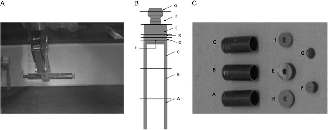
The unirradiated Zircaloy-4 sample is a 98-mm-long rod with an external diameter of 12 mm from which samples were cut in small discs. Its chemical composition is given by the “Material quality control certificate” (ASTM 2002). The irradiated Zircaloy-4 specimens originate from Belgian nuclear reactor. The upper part of the fuel tube was chosen for the corrosion tests. The fuel tube was cut in smaller pieces for the corrosion tests (Figure 1). A washing step was performed on these samples to decrease their activity by removing fission products and actinide contamination on the surface. This procedure consisted of washing the Zircaloy-4 pieces in 8 M nitric acid under reflux for 6.5 hr, followed by rinsing them once in 1 M nitric acid, once in ethanol and twice in demineralized water. Finally, samples are dried at room temperature. Pieces A, B, and C were used for simple immersion-corrosion tests and piece E, the thicker disc, was used for the potentiostatic corrosion tests. The dimensions and contact dose rate of these samples after the washing step are summarized in Table 1.
(A) Upper part of the irradiated Zircaloy-4 fuel cladding, (B) cutting scheme of the Zircaloy-4 cladding, and (C) photographs of the cut Zircaloy-4 cladding (Sample D is not shown in this picture).
Dimensions and weight of cut irradiated Zircaloy-4 samples.

Corrosion Tests
Electrochemical tests were performed with an EG&G Model 263A potentiostat. In preparation of potentiostatic corrosion tests, potentiodynamic polarization curves were recorded at a scan rate of 0.5 mV/sec to give information on the behavior of the metal at different potentials. This helped to choose the best potential range to apply during the potentiostatic corrosion tests.
Potentiostatic measurements were conducted for preliminary speciation determination. These tests were conducted in nitrogen atmosphere at an applied potential of –750 mV vs. Ag/AgCl on both unirradiated and irradiated samples in a 1450 mL glass vial containing three electrodes attached to the lid: (1) the working electrode (Zircaloy-4 sample), (2) the platinum counter electrode, and (3) the in-house made Ag/AgCl reference electrode. These electrodes constitute a traditional three-electrode setup described in the general literature on electrochemistry (Tait Reference Tait1994). The electrolyte used was a saturated Ca(OH)2 aqueous solution. For the unirradiated sample, the test was performed directly after immersion in the electrolyte. For the irradiated sample, the test was performed after the potentiodynamic polarization test, which lasted 2 hr.
Simple immersion corrosion tests aimed to investigate a more realistic corrosion behavior and associated carbon release and speciation. Simple immersion corrosion tests were carried out on irradiated samples placed in a 50-mL steel vial, equipped with a PEEK liner. The cell was filled with 35 mL of saturated portlandite pore water. After filling of the vials, they were screwed airtight. The tests were conducted under nitrogen conditions and lasted up to 195 days.
Manufacturing of the Electrodes
The working electrodes were manufactured by gluing a steel wire, serving as an electrical connection, to the back of the cut Zircaloy-4 samples. The glue used was a conductive silver epoxy (type CW2400, Circuitworks). Then, the specimens were embedded in a resin under a fume hood. Finally, specimens were mechanically wet-ground, with successively finer SiC papers, down to 500 grit, and then cleaned with double distilled water and finally left to dry in an argon atmosphere.
Analytical Methods
γ-ray spectrometry analyses were performed using two different HPGe detectors: one from Canberra (CAN2) and one from Ortec (ORT1). Both detectors were energy- and efficiency-calibrated over an energy range of 60 to 2000 keV using a γ-ray reference solution with a mixture of 10 different radionuclides. The ORT1 detector was calibrated using a 9ML01ELMA60 (2014) standard solution from LEA (Laboratoire Etalons d’Activité). The CAN2 detector was calibrated using a 12ML01ELMA60 standard source from LEA.
The nitrogen content of unirradiated samples was measured using an inert gas fusion method with a LECO TC436 model analyzer. The sample was cut into a small cube of ~0.5 g and stored in acetone until the analysis. Before sample analysis, at least three nitrogen blanks were measured and the results were normalized with the blanks. The instrument was calibrated using two certified reference materials of different concentration: AR649 with a nitrogen concentration of 44 μg/g and an oxygen concentration of 1200 μg/g (Alpha Ressources) and AR503-653 with a nitrogen concentration of 70 μg/g (LECO). The reported lower limit of detection of the method is approximately 1 μg/g for N. At least four replicate measurements were performed on each sample.
The carbon-14 computer modeling calculation was developed in the SCALE-6.1 code using the “Triton” depletion sequence.
Carbon speciation was determined by gas chromatography with a Shimadzu GC-2010 Plus type gas chromatograph (GC) equipped with a split/splitless injector, a “ShinCarbon ST” column and a pulsed discharge helium ionization detector (PDHID). The carrier gas was pure Argon. To remove any residual impurities, the carrier gas was passed through two gas purifiers (VICI Valco Instruments Co. Inc.) before it entered the GC column. A manual gas injection was made with a 500 µL gas tight syringe possessing a 5-cm-long needle. The detection limits for the most likely carbon compounds were determined in two ways: (1) by means of the noise in the vicinity of the peak of interest, and (2) by measuring standards of successive lower concentration until no (clear) peak was observed anymore. Table 2 shows the detection limits, taken as the average value (rounded up) of the detection limits determined by means of both methods. The value for carbon dioxide, however, seems to be extremely high but has to be considered with caution. In fact, it does not represent the real detection limit. Because a direct injection technique of the sample is used, some ambient air will inevitably enter the column (and the detector), which results in carbon dioxide contamination.
List of analyzed gases and their detection limits using the Shimadzu GC-2010 Plus with the PDHID detector.

RESULTS AND DISCUSSION
Carbon-14 Specific Activity
The activation of nitrogen-14 (14N(n,p)14C) is the most likely production pathway of carbon-14 in Zircaloy-4 (Wallace Reference Wallace1977). The nitrogen content analysis of the unirradiated Zircaloy-4 was performed on two different samples as it is the main precursor for carbon-14. The results are presented in Table 3. According to the literature (Blokhin et al. Reference Blokhin, Chernov, Blokhin, Denim and Sipachev2012) and/or technical specifications (ASTM 2013), the nitrogen content (CN) is usually between 40 and 80 µg/g. Values measured for SCK∙CEN samples are 2 to 4 times lower. This result leads to a decrease of the expected amount of carbon-14 inside the sample after irradiation.
Average nitrogen concentration (CN) and carbon-14 specific activity of Zircaloy-4 samples obtained from the computer simulation.

Based on this nitrogen content measurement in unirradiated Zircaloy-4, an estimation of the carbon-14 amount after irradiation of the metal was obtained using a computer modeling calculation, taking into account a standard Zircaloy-4 cladding composition and burnup of the fuel of 60 GWd/tU, which corresponds to a total neutron flux of 4.08×10²² n/cm² for the cladding. From the calculations, it appears that only 0.5% of nitrogen-14 produced carbon-14 at the end of irradiation. This leads to a carbon-14 concentration ranging from 8×10⁻² to 1.2×10⁻¹ µg/g of Zircaloy-4 and a carbon-14 specific activity of 13,300 to 19,600 Bq/g (Table 3).
Regarding the computer simulation of the carbon-14 concentration in the Zircaloy-4 samples and their expected low corrosion rate in high pH solutions, the carbon-14 release should be low during the corrosion tests performed in this work. After the washing step performed on the irradiated samples, the main part of the oxide layer formed during the irradiation step, and its carbon-14, should be removed. The main part of the carbon-14 is present in the Zircaloy-4 bulk. Therefore, its release, as well as the carbon-12 release, should be congruent with Zircaloy-4 corrosion. For these reasons, this work focuses on the carbon release and not only on the carbon-14 release.
Corrosion Experiments and Carbon Speciation
Two different corrosion tests were performed in this study. Simple immersion corrosion tests were performed to obtain information on the corrosion behavior of Zircaloy-4 in realistic geological disposal conditions while potentiostatic corrosion tests were performed to determine the electrochemical behavior of the investigated material. It has to be noted that potentiostatic corrosion tests were also performed with the sole aim to accelerate the corrosion process and determine the carbon speciation. For this reason, potentiostatic corrosion tests lasted only 7 days compared to the 195 days of the simple immersion corrosion tests.
Figure 2 presents the potentiodynamic polarization curves of irradiated and unirradiated Zircaloy-4 in saturated portlandite aqueous solution. Unirradiated Zircaloy-4 exhibited a corrosion potential near –1.04 V (vs. Ag/AgCl) and a broad passive range starting at –0.7 V (vs. Ag/AgCl). Irradiated Zircaloy-4 showed the same kind of behavior as the one obtained for the unirradiated sample, with the presence of a broad passive range starting at around –1.0 V (vs. Ag/AgCl) in the microampère current range. Note that the cathodic part of the curve was not recorded because the measurement started at the open circuit potential. It can be seen from Figure 2 that irradiation induced changes of the electrochemical behavior of Zircaloy-4. First, the corrosion potential shifted from –1.04 V (unirradiated) to ~1.23 V (irradiated) (vs. Ag/AgCl). Kim and Rebak (Reference Kim and Rebak2009) also found such a shift and assumed that it could be caused by an increase of the conductivity of the oxide film formed on the irradiated samples. Second, the passive current decreased from ~2.5×10⁻⁶ A (unirradiated) to ~1.5×10⁻⁶ A (irradiated). This second change seems to be in contradiction with the increase in conductivity of the oxide film or the published increase of the corrosion rate of zirconium alloys induced by irradiation (Motooka et al. Reference Motooka, Komatsu, Tsukada and Yamamoto2013; Tupin et al. Reference Tupin, Hamann, Cuisinier, Bossis, Blat, Ambard, Miquet, Kaczorowski and Jamard2015; Wang and Was Reference Wang and Was2015). However, these conclusions should be considered very carefully because only one test was performed and maybe these results all fall within the scatter of the experimental data.
Polarization curves of irradiated and unirradiated Zircaloy-4 sample in saturated portlandite aqueous solution.
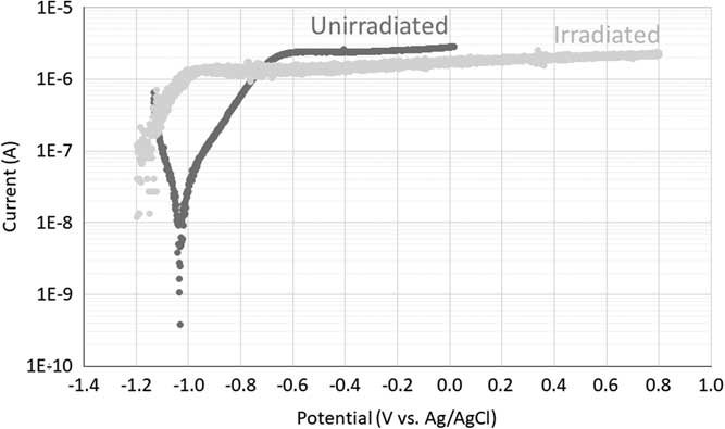
From these polarization curves, a potential of -0.75 V (vs. Ag/AgCl) was selected for the potentiostatic corrosion tests. The current is quite low at this potential (10–6 A) but it represents the highest current in the active corrosion zone of the polarization curve of the unirradiated sample, which is expected to result in the highest corrosion rate. For the irradiated sample, this potential falls in the passive corrosion zone. However, to stay in the stability domain of water the same potential was chosen for the potentiostatic corrosion tests on the irradiated Zircaloy-4 sample.
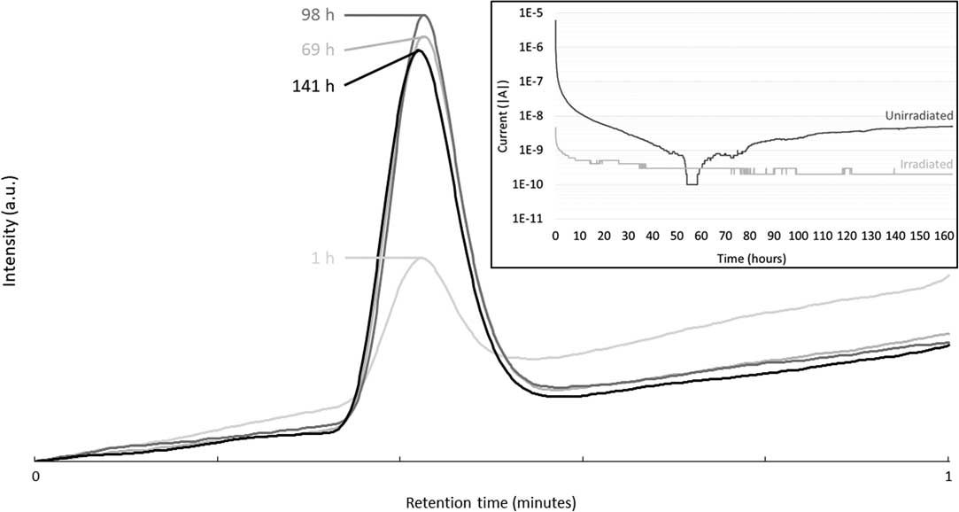
Potentiostatic corrosion tests were conducted for approximately seven days, while sampling of the gas phase was performed regularly. The gas phase was analyzed by gas chromatography to estimate the production of carbon-based molecules during corrosion. No light carbon-based molecules, such as methane, ethene, ethane, propene, propane or carbon dioxide, were detected during these tests (Figure not shown). However, at ~0.4 min of retention, a peak resulting from the presence of H2 is observed (Figure 3). The intensity of this peak slightly increases with corrosion time up to 69 hr. Then, the intensity of the H2 peak remained stable. Indeed, a cubic law initially represents the corrosion of Zircaloy-4 at high pH (Kato et al. Reference Kato, Tanabe, Sakuragi, Nishimura and Tateishi2014). Moreover, a decrease of the current until a few nanoAmpère or less were observed after only a few hours of corrosion, confirming this cubic law (see inset of Figure 3).
Gas chromatograms of gas sampling from the headspace of the potentiostatic corrosion vial at different corrosion times of the unirradiated Zircaloy-4 sample in Ca(OH)2 electrolyte. Inset: Current as a function of corrosion time of the irradiated and unirradiated Zircaloy-4 samples.
From the current as a function of the time curves, it was also possible to calculate the total charge as well as the amount of corroded metal. It appeared that a corrosion rate of ~54 nm/yr is obtained if it is assumed that all the recorded current originates from the corrosion of the unirradiated Zircaloy-4. However, this corrosion rate is an upper limit because the measured current can come not only from the corrosion but also from any other electrochemical reaction at the surface of the electrode. IAEA suggested a corrosion rate of 20 nm/yr for Zircaloy-4 (IAEA 1998b; IAEA 2006). This calculation of ~54 nm/yr looks then very high, indicating the conservative nature of this rate.
From the corrosion of the irradiated sample, a corrosion rate of ~4 nm/yr is obtained considering the same assumption. This value is lower than the one obtained for the unirradiated sample and than the conservative value suggested by IAEA (IAEA 1998b; IAEA 2006). This could be due to the fact that the passive layer was already present at the beginning of this test. Indeed, the potentiostatic test was performed directly after recording the polarization curve without applying an extra polishing step. Considering the short length of the corrosion exposure, the uncertainty on the obtained rate is high. In any case, the recorded values should be considered with caution and more measurements would be needed for confirmation.
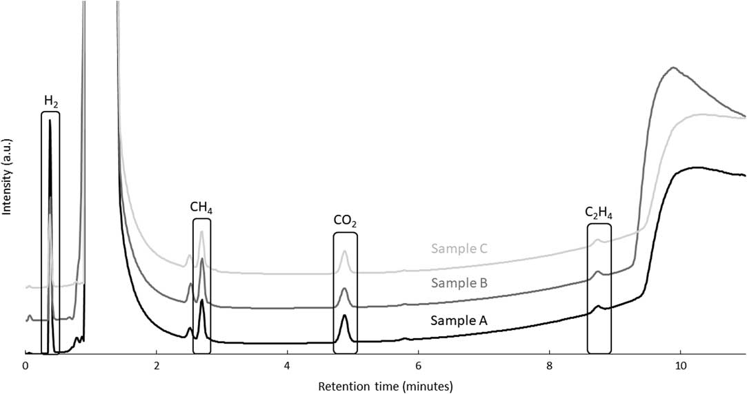
Simple immersion corrosion tests were performed on irradiated samples A, B, and C (Figure 1). Unirradiated samples were not tested. After 195 leaching days, samplings from the gas phase accumulated in the headspace of the vial were analyzed by gas chromatography. Even if the corrosion rate was expected to be low, the detection and separation of peaks for carbon-based gas were obtained. The formation of those molecules is proposed to occur through mechanisms comparable to the Fischer-Tropsch synthesis (Henrici-Olive and Olive Reference Henrici-Olive and Olive1976; Deng et al. Reference Deng, Campbell and Burris1997). Chromatograms obtained for the three samples gave similar results (Figure 4; Table 4). It can be seen from Figure 4 that methane, carbon dioxide and ethene can clearly be distinguished with methane being the major contributing component. The measured concentrations are low, but are well above the detection limit, except for carbon dioxide (Table 2). Between 9 and 10 minutes of retention, a bump in the GC chromatograms is observed, which can be attributed to water. Unfortunately, this bump can interfere with the ethane peak. Therefore, it becomes impossible to know if this gas was formed (or not) during the corrosion of Zircaloy-4 samples. A peak attributed to hydrogen was also detected, however, its concentration could not be determined quantitatively.
Gas chromatograms of gas sampling from the headspace of the simple immersion corrosion vials of the irradiated Zircaloy-4 sample in saturated portlandite pore water after 195 days.
Calculated concentrations of methane, ethane, and carbon dioxide in the gas phase after simple immersion corrosion tests of Zircaloy 4 in portlandite pore water (duration 195 days).

Knowing the production of the carbon-based compounds in the gas phase and the carbon concentration in the bulk, an approximation of the corrosion rate was determined. If it is assumed that all the carbon, present in the bulk and released during corrosion, was transformed in carbon-based gas, a corrosion rate of 57±4 nm/yr was calculated. In the case where the detected CO2 was taken into account in the calculation, a corrosion rate of 84±17 nm/yr was calculated. Indeed, the uncertainty on the CO2 concentration in the gas phase is high due to the injection method used. These values are in the same range as the corrosion rate calculated from the electrochemical measurement of the unirradiated sample, but they are significantly higher compared to the conservative corrosion rate of 20 nm/yr suggested by IAEA (IAEA 1998b, 2006).
Carbon-based compounds are likely to be release in the liquid phase, leading to a higher corrosion rate. However, due to the high uncertainties on these measurements and/or the low concentration, the determination of the carbon and carbon-14 concentration in solution with TIC/TOC (total (in)organic carbon) and LSC (liquid scintillation counting) did not allow to obtain more information. For this reason, this study focused only on the carbon speciation and the carbon released in the gas phase.
Even if corrosion was reproducible for the three tests, this value should be considered with caution. Indeed, due to the washing step, initially performed to reduce the activity of the samples, the oxide layer formed at the surface of the Zircaloy-4 sample was at least partially removed, which might have led to possible changes in the corrosion rate.
Another method to calculate the corrosion rate could be the quantification of the produced hydrogen during the Zircaloy-4 corrosion. This will be discussed in a future communication.
CONCLUSIONS
This work investigated the release of carbon from Zircaloy-4 representative for the fuel cladding as used in the Belgian nuclear power plants, and the carbon speciation in a cementitious environment, which is relevant for the Belgian Supercontainer design, as perceived for the geological disposal of high-level waste. To achieve this, two different corrosion tests were performed: (1) simple immersion corrosion tests to obtain information on the Zircaloy-4 behavior in realistic geological disposal conditions; these tests were only realized on irradiated samples, and (2) potentiostatic corrosion tests to investigate the electrochemical behavior including the corrosion mechanism and speciation of light carbon molecules formation.
Before starting the potentiostatic corrosion tests, polarization curves were recorded to obtain information on the electrochemical behavior of the Zircaloy-4 samples. Irradiation seemed to induce some difference in the sample behavior such as the shift of the corrosion potential to a more reductive potential.
The analysis of the gas phase by GC, obtained with a Pulse Discharge Helium Ionization Detector (PDHID) detector, revealed the production of methane, ethene and potentially carbon dioxide after the 195 days duration of the simple immersion corrosion tests on irradiated Zircaloy-4, with methane being the major compound. Based on the measured gas concentrations, an approximation of the corrosion rate was calculated (57–84 nm/yr). Even though no carbon-based products could be measured after the potentiostatic corrosion tests, the analysis of the electrical current produced during this test suggested a corrosion rate of 54 nm/yr for the unirradiated sample and a lower value of 4 nm/yr for the irradiated sample. This lower value is maybe due to the presence of a passive film formed on this sample after the potentiodynamic test. However, caution has to be taken on these corrosion rates and more tests should be performed to confirm these results. The quantification of the produced hydrogen during the Zircaloy-4 corrosion could also be used to calculate its corrosion rate. This will be discussed in a future communication.
ACKNOWLEDGMENTS
The research leading to these results has received funding from the “European Union’s European Atomic Energy Community’s (Euratom) Seventh Framework Programme FP7/2007-2013 under grant agreement no. 604779, the CAST project”. The authors gratefully acknowledge the financial support of this work by ONDRAF/NIRAS, the Belgian national radioactive waste management organization. The authors acknowledge also Pieter Schroeders, Steven Smets, Ben Gielen, Sabrina Lunardi, and Wim Verwimp for the technical support and Kevin Govers for his help with the computer simulation.


 Open access