

1. INTRODUCTION
Ice is a common mineral on the Earth's surface. Thick ice sheets cover Greenland and Antarctica. How much ice is stored in these ice sheets depends on its mechanical properties, as the weight of the ice masses causes a steady flow of ice towards the surrounding oceans. The mechanical properties of ice, therefore, directly impact on human society through its role in controlling sea level (Kennicutt and others, Reference Kennicutt2014). At natural strain-rates of <10−6 s−1 (e.g. Budd and Jacka, Reference Budd and Jacka1989), ice is a ductile material, assumed to deform dominantly by dislocation creep (e.g. Schulson and Duval, Reference Schulson and Duval2009), similar to other rock-forming minerals, such as quartz and olivine at much higher absolute, but similar homologues temperatures. In contrast to these minerals, ice on Earth only occurs very close to its melting temperature.
Ice on Earth is exclusively Ih, with a hexagonal structure. The strong viscoplastic anisotropy of single ice crystals constitutes the first complexity in describing and modelling the behaviour of the flow of ice (Duval and Castelnau, Reference Duval and Castelnau1995). The critical resolved shear stress (CRSS) to activate dislocation slip on the basal plane is ~60–100 times lower than on prismatic and pyramidal planes (Duval and others, Reference Duval, Ashby and Anderman1983; Wilson and Zhang, Reference Wilson and Zhang1996; Montagnat and others, Reference Montagnat2013). Strain is therefore mostly achieved by slip on the basal plane, with relatively minor contributions of the other slip planes (Ashby and Duval, Reference Ashby and Duval1985).
The bulk behaviour of large ice masses results from the behaviour of the ensemble of individual ice grains. This behaviour is thus strongly influenced by the viscoplastic anisotropy of these grains and the orientation of their lattices, usually expressed in the orientation of their c-axes. During flow, ice quickly develops a lattice preferred orientation (LPO) by lattice rotation (Azuma and Higashi, Reference Azuma and Higashi1985; Alley, Reference Alley1988, Reference Alley1992; Jacka and Li, Reference Jacka and Li2000). The ice microstructure further evolves through time by recrystallisation, that is any re-orientation of the lattice caused by grain boundary migration (GBM) and/or formation of new grain boundaries (GBs; see Glossary in Faria and others, Reference Faria, Weikusat and Azuma2014a, Reference Faria, Weikusat and Azumab, Reference Faria, Kipfstuhl and Lambrechtc), which is driven by GB surface energy and strain energy. The mechanical properties of ice masses are therefore not constant, but are the result of complex, time-dependent coupling between deformation and microstructural evolution. Understanding this coupling is of paramount importance for studies on the flow behaviour of polar ice sheets.
1.1. Flow of polar ice sheets
Experiments on ice show it has a strongly strain-dependent behaviour (Jacka, Reference Jacka1984; Azuma, Reference Azuma1994; Treverrow and others, Reference Treverrow, Budd, Jacka and Warner2012; Budd and others, Reference Budd, Warner, Jacka, Li and Treverrow2013). Initial, transient or primary creep is dominated by dislocation glide on the basal plane and is associated with an increase in strength (Montagnat and others, Reference Montagnat, Weiss, Chevy, Duval, Brunjail, Bastie and Gil Sevillano2006). Secondary creep is reached at a few percentage strain, when recrystallisation sets in, the maximum strength is reached and thereby the material begins to soften again (Glen, Reference Glen1955). An LPO develops during tertiary creep where a steady state may be reached after ~10% strain (Budd and Jacka, Reference Budd and Jacka1989; Treverrow and others, Reference Treverrow, Budd, Jacka and Warner2012). Although secondary creep is highly transient, it is the stage on which the commonly used flow law is based. ‘Glen's law’ (Glen, Reference Glen1958) describes the relation between deviatoric stress (σ) and strain-rate ( $\dot \varepsilon $
) by a power law with a stress exponent, n:
$\dot \varepsilon $
) by a power law with a stress exponent, n:
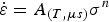 $$\dot \varepsilon = {A_{\left( {T{\rm,} \mu s} \right)}}{\sigma ^n}$$
This law is based on the maximum strength that is reached during secondary creep. In most studies, it is assumed that n = 3, although values ranging from 1 to 5 have also been reported, for example, based on experiments (Goldsby and Kohlstedt, Reference Goldsby and Kohlstedt2001) and observations on ice sheets (Cuffey and Kavanaugh, Reference Cuffey and Kavanaugh2011; Gillet-Chaulet and others, Reference Gillet-Chaulet, Hindmarsh, Corr, King and Jenkins2011). The pre-exponential factor depends on temperature (T), but also on the microstructure (μs), in particular the LPO. The effect of LPO is usually incorporated by using an LPO-dependent scalar ‘enhancement factor’ (see Faria and others, Reference Faria, Weikusat and Azuma2014b). This enhancement factor changes the absolute strain-rate at a given stress, but not the sensitivity of strain-rate to a change in stress, defined by n.
1.2. Microstructures of deforming ice
Laboratory experiments and deep drill cores through glaciers and ice sheets are the most important sources of information on ice microstructures (e.g. Weikusat and others, Reference Weikusat, Kipfstuhl, Faria, Azuma and Miyamoto2009; Piazolo and others, Reference Piazolo2012; Wilson and others, Reference Wilson, Peternell, Piazolo and Luzin2013; Faria and others, Reference Faria, Weikusat and Azuma2014a, Reference Faria, Weikusat and Azumab). The three dominant processes that affect the shape and size of grains are sub-grain formation or polygonisation, GBM driven by strain energy and grain growth by surface energy (Urai and others, Reference Urai, Means, Lister and Hobbs1986). All three processes operate concurrently, albeit in different proportions, mainly depending on strain-rate and temperature (Faria and others, Reference Faria, Weikusat and Azuma2014b). Grain boundary surface energy-driven grain growth in isolation (‘normal grain growth’; NGG) leads to an increase in grain size by reduction of GB surface area (Azuma and others, Reference Azuma, Miyakoshi, Yokoyama and Takata2012). Polygonisation, in geology also termed ‘rotational recrystallisation’ (RRX) (Urai and others, Reference Urai, Means, Lister and Hobbs1986), is a recovery process whereby the lattices in regions within grains rotate relative to each other by the formation of tilt walls. Progressive rotation causes tilt walls to become true GBs, which causes a reduction of the grain size. A dynamic balance between grain growth and polygonisation is invoked by some authors (Mathiesen and others, Reference Mathiesen2004; Durand and others, Reference Durand, Persson, Samyn and Svensson2008; Roessiger and others, Reference Roessiger2011, Reference Roessiger, Bons and Faria2012; Azuma and others, Reference Azuma, Miyakoshi, Yokoyama and Takata2012). The third process, also called ‘strain-induced boundary migration’ (SIBM) (Urai and others, Reference Urai, Means, Lister and Hobbs1986; Drury and Urai, Reference Drury and Urai1990; Tullis and others, Reference Tullis, Dell'Angelo, Yund, Ramberg, Hemin and Mancktelow1990; Stipp and Tullis, Reference Stipp and Tullis2003) is driven by the energy stored within the lattice in the presence of dislocations. Variations in stored energy (or strain energy) cause GBs to bulge into regions with highest stored energy, leading to the formation of irregular or lobate GBs.
Based on grain-size profiles, it is proposed that the three recrystallisation processes dominate at different depths (De la Chapelle and others, Reference De La Chapelle, Castelnau, Lipenkov and Duval1998): NGG in the upper few hundreds of meters, followed by RRX and finally SIBM in the lowest few hundreds of meters in ice sheets, where a sudden increase in grain size is observed in drill cores (e.g. Faria and others, Reference Faria, Weikusat and Azuma2014a). However, several authors (Kipfstuhl and others, Reference Kipfstuhl2006, Reference Kipfstuhl2009; Weikusat and others, Reference Weikusat, Kipfstuhl, Faria, Azuma and Miyamoto2009; Faria and others, Reference Faria, Kipfstuhl and Lambrecht2014c) have challenged the tri-partite model for ice sheets and showed that all three processes operate at all levels, albeit in different proportions, decoupling the recrystallisation phenomenon from simple depth considerations and describing grain size evolution by strain-rate and temperature conditions (Faria and others, Reference Faria, Kipfstuhl and Lambrecht2014c).
Dislocation creep is assumed to be largely insensitive to grain size and shape (Poirier, Reference Poirier1985; Schulson and Duval, Reference Schulson and Duval2009). However, recrystallisation is expected to strongly influence flow properties of ice, if it influences the LPO (Duval and Castelnau, Reference Duval and Castelnau1995; Duval and others, Reference Duval, Arnaud, Brissaud, Montagnat and de La Chapelle2000; Kocks and others, Reference Kocks, Tomé and Wenk2000). For example, if crystals with certain orientations are more prone than others to be consumed by migrational recrystallisation owing to their higher dislocation density, migrational recrystallisation would directly influence the LPO, and hence the strength. The study of the interaction between deformation and recrystallisation is thus clearly relevant to improve our understanding and quantification of the flow of ice, from a small volume to that of polar ice sheets.
1.3. Numerical modelling of microstructural evolution in ice
Much insight in the mechanical and microstructural behaviour of ice has been gained from experiments (Azuma and Higashi, Reference Azuma and Higashi1985; Wilson, Reference Wilson and Hobbs1986; Budd and Jacka, Reference Budd and Jacka1989; Jacka and Li, Reference Jacka and Li2000; Treverrow and others, Reference Treverrow, Budd, Jacka and Warner2012; Piazolo and others, Reference Piazolo2012). However, one major limitation of experiments is that deformation rates are inevitably higher than those typical in nature by several orders of magnitude, especially in case of slowly flowing polar ice sheets (ε ≈ 1010−10−13 s−1; Budd and Jacka, Reference Budd and Jacka1989; Montagnat and Duval, Reference Montagnat and Duval2004). Numerical modelling provides a solution to this, as it is limited by computational power and the sophistication of the algorithms, but not by scale, stress or strain-rate.
Theoretical and computational studies have been performed for many years in order to understand the deformation and microstructural evolution (Sachs, Reference Sachs1928; Taylor, Reference Taylor1938). Crystal plasticity based finite element (FE) implementations have been used in the past to model plastic deformation of polycrystalline materials (Becker, Reference Becker1991; Mika and Dawson, Reference Mika and Dawson1998; Raabe and others, Reference Raabe, Sachtleber, Zhao, Roters and Zaefferer2001; Delannay and others, Reference Delannay, Logé, Chastel, Signorelli and Van Houtte2003; Diard and others, Reference Diard, Leclercq, Rousselier and Cailletaud2005). However, the large number of degrees of freedom needed in FE calculations, which restricts the size of the simulated microstructure and the use of averaged properties, are important limitations. To overcome these and to be able to predict the micromechanical behaviour, a full-field formulation based on fast Fourier transforms (FFT) (Moulinec and Suquet, Reference Moulinec and Suquet1994) is used to simulate plastic deformation in heterogeneous materials, such as composites (Moulinec and Suquet, Reference Moulinec and Suquet1998; Michel and others, Reference Michel, Moulinec and Suquet2000; Idiart and others, Reference Idiart, Moulinec, Ponte Castaneda and Suquet2006) or polycrystals (Lebensohn, Reference Lebensohn2001; Lebensohn and others, Reference Lebensohn, Liu and Castañeda2004, Reference Lebensohn, Castelnau, Brenner and Gilormini2005, Reference Lebensohn, Brenner, Castelnau and Rollett2008). Polycrystal full-field models differ from mean-field models (Sachs, Reference Sachs1928; Taylor, Reference Taylor1938; Lebensohn and Tomé, Reference Lebensohn and Tomé1993) in that the latter explicitly or implicitly assume homogeneous deformation at single crystal level.
Previous full-field simulations applied to ice were mostly limited to low-finite strain (<4% of shortening; Montagnat and others, Reference Montagnat, Blackford, Piazolo, Arnaud and Lebensohn2011) with the exception of a brief example of high-strain FFT modelling by Montagnat and others (Reference Montagnat2013). Most studies dealing with FFT-modelling of ice only considered viscoplastic deformation and only a few include recrystallisation (Durand, Reference Durand2004; Montagnat and others, Reference Montagnat2013). Considering that ice is near to its melting point at natural conditions, a numerical study on ice recrystallisation processes coetaneous with deformation up to high-strain, the subject of this paper, is long overdue.
In this contribution, we present models combining FFT-based simulations to determine local plastic deformation with recrystallisation up to high-strain. The model will be illustrated with pure-shear, plane-strain deformation of pure, polycrystalline Ih ice. We will show how recrystallisation has a major effect on the microstructure, but, perhaps counter-intuitively, only a minor effect on LPO development. Although LPO's do not vary much, recrystallisation appears to have a distinct effect on the relative activities of slip systems. A limitation of the present approach is that only GBM and sub grain formation were considered in the simulations. However, formation of new high-angle GBs due to subgrain rotation or nucleation in highly deformed regions is not yet implemented.
2. METHODS
In this study, we numerically model the microstructural evolution of an aggregate of pure ice grains during deformation and recrystallisation in 2-D pure shear. The approach is based on the coupling between modelling deformation of the viscoplastic polycrystal with a full-field theory formulation (numerically implemented in the FFT code by Lebensohn (Reference Lebensohn2001) and Lebensohn and others (Reference Lebensohn, Brenner, Castelnau and Rollett2008)) and the microstructural modelling platform, ELLE (Jessell and others, Reference Jessell, Evans, Barr and Stüwe2001a; Bons and others, Reference Bons, Koehn, Jessell, Bons, Koehn and Jessell2008) designed to simulate recrystallisation processes. The FFT approach provides the stress and velocity fields, from which deformation induced lattice rotation and an estimate of geometrically necessary dislocation densities are calculated. These data, as well as a map of the grain boundary network are used to simulate intracrystalline recovery and GBM driven by the reduction of surface energy and stored strain energy generated by dislocations.
The data structure of the models consists of two basic layers (Fig. 1a and b): (1) a contiguous set of polygons (termed flynns) that are themselves defined by boundary nodes (bnodes) and connected by straight boundary segments and (2) a set of unconnected nodes (unodes) that provide a higher resolution of physical properties within grains. The correspondence between both codes is done using the unodes layer that allows a direct mapping between the regular computational grid required by the FFT code and the material information required by ELLE.
Basic data structure and set up of the simulations. The ELLE data structure has two different layers: (a) boundary nodes (double or triple nodes) that define polygons (grains), (b) a regular mesh of unconnected nodes to store dislocation density and lattice orientations used for the FFT calculation. Initially 2 × 1 model with 3260 grains (c) is deformed in pure shear with 2% vertical shortening every step (d).

In the next sections, we briefly provide the basics of the governing and constitutive equations and numerical implementation of both approaches.
2.1. Viscoplastic deformation – FFT
The FFT-based formulation provides an exact solution of the mechanical problem by finding a strain-rate field and a stress field, associated with a kinematically admissible velocity field, which minimises the average local work rate under the compatibility and equilibrium constraints (see Lebensohn, Reference Lebensohn2001; Lebensohn and others, Reference Lebensohn, Brenner, Castelnau and Rollett2008 for a detailed description of the method, and Montagnat and others, Reference Montagnat2013 for its application to ice). The method is based on the fact that the local mechanical response of a periodic heterogeneous medium can be calculated as a convolution integral between the Green function of a linear reference homogeneous medium and the actual heterogeneity field. The use of the FFT algorithm reduces the convolution integrals in Cartesian space to simple products in Fourier space and allows us to obtain the mechanical fields by transforming that product back to real space. As the heterogeneity field depends on the unknown mechanical field, an augmented Lagrangian-based iterative scheme is used to determine stress and strain-rate fields that fulfil the compatibility and equilibrium constraints (Michel and others, Reference Michel, Moulinec and Suquet2001). In general, the FFT approach has a better numerical performance than simulations based on the FE Method (Prakash and Lebensohn, Reference Prakash and Lebensohn2009; Roters and others, Reference Roters, Eisenlohr, Bieler and Raabe2011), but it is restricted to periodic boundary conditions and requires discretisation into a regular grid.
The constitutive behaviour of a polycrystal aggregate is defined using a nonlinear viscous rate-dependent crystal plasticity approach where deformation on the crystal scale is assumed to be accommodated by dislocation glide only. The constitutive equation between the strain-rate and the deviatoric stress σ'(x) at position x is defined using a nonlinear viscous response given by
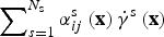
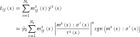 $$\eqalign{{{\dot \varepsilon} _{ij}}\left( x \right) & = \mathop \sum \limits_{s{\rm = 1}}^{{N_{\rm s}}} m_{ij}^{\rm s} \left( x \right){{\dot \gamma} ^{\rm s}}\left( x \right) \cr & = {{\dot \gamma} _0}\mathop \sum \limits_{s = 1}^{{N_{\rm s}}} m_{ij}^{\rm s} \left( x \right){\left \vert {\displaystyle{{{m^{\rm s}}\left( x \right):\sigma ^{\prime}\left( x \right)} \over {{\tau ^{\rm s}}\left( x \right)}}} \right \vert ^n}sgn\left( {{m^{\rm s}}\left( x \right):\sigma ^{\prime}\left( x \right)} \right)} $$
where the sum runs over all N
s slip systems, m
s is the symmetric Schmid tensor defined by the dyadic product of the vector normal to the glide plane and the Burgers vector of slip system s, and ${\dot \gamma ^{\rm s}}$
and τ
s are, respectively, the shear strain-rate and the CRSS of slip system s,
${\dot \gamma ^{\rm s}}$
and τ
s are, respectively, the shear strain-rate and the CRSS of slip system s, ${\dot \gamma _0}$
is a reference strain-rate and n the stress exponent (inverse of the strain-rate sensitivity). The CRSS associated with each material point can potentially change according to a hardening or softening law (e.g. Lebensohn and others, Reference Lebensohn, Brenner, Castelnau and Rollett2008). This was not considered in this study, where all CRSSs are kept constant during simulations.
${\dot \gamma _0}$
is a reference strain-rate and n the stress exponent (inverse of the strain-rate sensitivity). The CRSS associated with each material point can potentially change according to a hardening or softening law (e.g. Lebensohn and others, Reference Lebensohn, Brenner, Castelnau and Rollett2008). This was not considered in this study, where all CRSSs are kept constant during simulations.
After each time increment Δt, the microstructure is updated using an explicit scheme. The new position of a point X of the Fourier grid is determined using the velocity fluctuation term ${\tilde v_{\rm i}}\left( {\bf x} \right)$
(Eqn (25) in Lebensohn, Reference Lebensohn2001) arising from the heterogeneity field as
${\tilde v_{\rm i}}\left( {\bf x} \right)$
(Eqn (25) in Lebensohn, Reference Lebensohn2001) arising from the heterogeneity field as
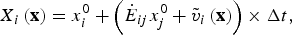 $${X_i}\left( {\bf x} \right) = x_i^0 + \left( {{{\dot E}_{ij}}x_j^0 + {{\tilde v}_i}\left( {\bf x} \right)} \right) \times \Delta t,$$
where ${\dot E_{ij}}$
is the macroscopic strain-rate. The local crystallographic orientations are updated according to the local lattice rotation,
${\dot E_{ij}}$
is the macroscopic strain-rate. The local crystallographic orientations are updated according to the local lattice rotation,
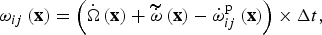 $${\omega _{ij}}\left( {\bf x} \right) = \left( {{\dot \Omega} \left( {\bf x} \right) + \widetilde{{\dot \omega}} \left( {\bf x} \right) - \dot \omega _{ij}^{\rm p} \left( {\bf x} \right)} \right) \times \Delta t,$$
where ${\dot \Omega} \left( {\bf x} \right)$
is the average rotation rate of the macroscopic velocity gradient tensor,
${\dot \Omega} \left( {\bf x} \right)$
is the average rotation rate of the macroscopic velocity gradient tensor, $\widetilde{{\dot \omega}} \left( {\bf x} \right)$
is the local fluctuation in rotation-rate obtained by taking the anti-symmetric part of the fluctuation term
$\widetilde{{\dot \omega}} \left( {\bf x} \right)$
is the local fluctuation in rotation-rate obtained by taking the anti-symmetric part of the fluctuation term ${\tilde v_i}\left( {\bf x} \right)$
and
${\tilde v_i}\left( {\bf x} \right)$
and $\dot \omega _{ij}^{\rm p} \left( {\bf x} \right)$
is the plastic rotation-rate of the crystal lattice, calculated as
$\dot \omega _{ij}^{\rm p} \left( {\bf x} \right)$
is the plastic rotation-rate of the crystal lattice, calculated as $\sum\nolimits_{s{\rm = 1}}^{{N_{\rm s}}} {\alpha _{ij}^{\rm s} \left( {\bf x} \right){{\dot \gamma} ^{\rm s}}\left( {\bf x} \right)} $
, where
$\sum\nolimits_{s{\rm = 1}}^{{N_{\rm s}}} {\alpha _{ij}^{\rm s} \left( {\bf x} \right){{\dot \gamma} ^{\rm s}}\left( {\bf x} \right)} $
, where $\alpha _{ij}^{\rm s} $
is the anti-symmetric Schmid tensor.
$\alpha _{ij}^{\rm s} $
is the anti-symmetric Schmid tensor.
An estimate of the dislocation-density field can be found using the strain gradient plasticity theory (e.g., Fleck and Hutchinson, Reference Fleck and Hutchinson1997; Gudmundson, Reference Gudmundson2004; Wen and others, Reference Wen, Huang, Hwang, Liu and Li2005), based on Ashby's concept of geometrically necessary dislocations (GND) (Ashby, Reference Ashby1970). Following this approach, GND are required to maintain strain compatibility across the material. The presence of GND (ρ) produces a strain energy storage associated with lattice distortion that, according to Ashby (Reference Ashby1970), is related to the absolute value of the effective plastic strain gradient (e.g. Brinckmann and others, Reference Brinckmann, Siegmund and Huang2006; Estrin and Kim, Reference Estrin and Kim2007)
 $$\rho = \displaystyle{{{\eta ^{\rm p}}} \over b},$$
where b is the magnitude of the Burgers vector and η p is the effective plastic strain gradient derived by Gao and others, (Reference Gao, Huang, Nix and Hutchinson1999) as
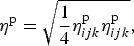 $${\eta ^{\rm p}} = \sqrt {\displaystyle{1 \over 4}\eta _{ijk}^{\rm p} \eta _{ijk}^{\rm p}}, $$
and
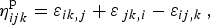 $$\eta _{ijk}^{\rm p} = {\varepsilon _{ik{\rm,} j}} + {\varepsilon _{\,jk{\rm,} i}} - {\varepsilon _{ij{\rm,} k{\rm \;}}}, $$
where ε ik,j indicates the partial derivatives of the plastic strain tensor with respect to the reference coordinates. Although other, higher order approaches to calculate the dislocation densities resulting from the activity of each slip systems are possible (see e.g. Ma and others, Reference Ma, Roters and Raabe2006; Roters and others, Reference Roters2010), or the Nye's dislocation density tensor can be used (e.g., Nye, Reference Nye1953; Kröner, Reference Kröner1962; Ashby, Reference Ashby1970), we simplify our approach by assuming a constant Burgers vector for all systems, and therefore, dislocations arising from basal and nonbasal slip systems are not differentiated. Furthermore, statistically stored dislocations, dislocation tangles, etc. are not considered as their type, activity and density cannot be determined from the model calculations, but would require additional assumptions. Dynamic dislocation effects, such as avalanches (Weiss and Marsan, Reference Weiss and Marsan2003) are also not considered for the same reason.
2.2. Recrystallisation – ELLE
The numerical platform, ELLE was used in this study to simulate the recrystallisation processes. The modular programming of ELLE provides a highly versatile data transfer and allows coupling between various processes that affect a microstructure (Jessell and others, Reference Jessell, Evans, Barr and Stüwe2001a, Reference Jessell, Bons, Evans, Barr and Stüweb; Bons and others, Reference Bons, Koehn, Jessell, Bons, Koehn and Jessell2008; Piazolo and others, Reference Piazolo, Jessell, Bons, Evans and Becker2010). ELLE has been used to simulate a variety of microstructural processes, including dynamic recrystallisation (DRX) (Piazolo and others, Reference Piazolo, Bons, Jessell, Evans and Passchier2002, Montagnat and others, Reference Montagnat2013), grain growth (Jessell and others, Reference Jessell, Bons, Evans, Barr and Stüwe2001b; Jessell and others, Reference Jessell, Kostenko and Jamtveit2003; Roessiger and others, Reference Roessiger2011), strain localisation (Jessell and others, Reference Jessell, Siebert, Bons, Evans and Piazolo2005; Griera and others, Reference Griera2011), porphyroclast rotation (Griera and others, Reference Griera2013), deformation of two phase materials (Jessell and others, Reference Jessell, Bons, Griera, Evans and Wilson2009) and folding (Llorens and others, Reference Llorens, Bons, Griera, Gomez-Rivas and Evans2013a, Reference Llorens, Bons, Griera and Gomez-Rivasb).
In this study, GBM and recovery processes are used in order to simulate the microstructural evolution by recrystallisation. GBM covers the motion or displacement of high-angle boundaries (HAGB), whereby lattice distortions in swept regions are restored. Recovery is the decrease in intracrystalline heterogeneities by means of local rotation of the lattice without motion of HAGBs.
2.3. GBM
The model aims to simulate GBM that is driven by reduction of the GB energy and stored strain energy resulting from lattice distortions (i.e. dislocation density). For a single-phase, polycrystalline aggregate, the velocity of a grain boundary is expressed as
 $$\vec v = M\Delta f\vec n,$$
where M corresponds to the boundary mobility, Δf to the driving pressure (force divided by GB area it acts on) and $\vec n$
to the unit vector normal to the boundary in the direction of movement. The GB mobility is highly dependent on temperature and can be expressed using an Arrhenius or exponential equation
$\vec n$
to the unit vector normal to the boundary in the direction of movement. The GB mobility is highly dependent on temperature and can be expressed using an Arrhenius or exponential equation
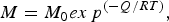 $$M = {M_0}ex{\,p^{( - Q/RT)}},$$
where M 0 is the intrinsic mobility, Q is the boundary-diffusion activation energy, R is the universal gas constant (e.g. Gottstein and Mecking, Reference Gottstein and Mecking1985). The driving pressure Δf is defined as
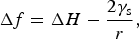 $$\Delta f = \Delta H - \displaystyle{{2{\gamma _{\rm s}}} \over r},$$
where ΔH is the difference in stored strain energy density across the grain boundary, γ s to the boundary energy and r to the local radius of curvature of the grain boundary. The stored energy ΔH is calculated using the difference in dislocation density Δρ across a grain boundary and the energy of a dislocation per unit length E ρ (Cottrell, Reference Cottrell1953; Karato, Reference Karato2008):
 $$\Delta H = \mathop \sum \limits_{s = 1}^{{N_{\rm s}}} {\left( {\Delta \rho {E_\rho}} \right)_{\rm s}} = \mathop \sum \limits_{s = 1}^{{N_{\rm s}}} {\left( {\rho \displaystyle{{G{b^2}} \over {4\pi P}}\log \displaystyle{{{R_{\rm e}}} \over {{b_0}}}} \right)_{\rm s}}\sim \Delta \rho G{b^2},$$
where G is the shear modulus, P is a constant that depends on dislocation type and Poisson's ratio, b
0 is the radius of the dislocation core and R
e is the upper limit for integration of the distance from the dislocation line. As the dislocation density for each slip system is unknown, we make the assumption that the elastic energy is the same for all slip systems and Eqn (11) can be approximated to
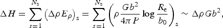
 $\Delta H \sim \Delta \rho G{b^2}$
(e.g. Cottrell, Reference Cottrell1953; Karato, Reference Karato2008).
$\Delta H \sim \Delta \rho G{b^2}$
(e.g. Cottrell, Reference Cottrell1953; Karato, Reference Karato2008).
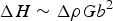
GBM is simulated using a front-tracking approach based on the algorithm by Becker and others (Reference Becker, Bons and Jessell2008) and recently used by Roessiger and others (Reference Roessiger, Bons and Faria2012) to simulate grain growth of ice with air bubbles. In this algorithm, the motion of boundaries is driven by minimisation of the Gibbs free energy, according to Eqn 10. For each time increment, each bnode is moved over a small distance assuming that the velocity does not change during the small time increment. In order to predict the direction and magnitude of the bnode displacement, four orthogonal trial positions at very small distance from the current node position are chosen. The change of total energy (E j ) for each trial position is due to (1) the change in total boundary length, and therefore the change of total boundary energy and (2) the decrease of dislocation density due to the removal of all dislocations in the swept area,
 $${E_j} = {A_j}\overline {{\rho _j}} {E_\rho} - \gamma \mathop \sum \limits_{i{\rm = 1}}^N {l_i}\;, $$
where A
j
, $\; \overline {{\rho _j}} $
and l
i
correspond to the swept area, to the average dislocation density of the swept area and the length of the boundary segments due to the j-th trial position, respectively. N is the number of segments (two or three) that connect at the node under consideration. From the four E
j
values, the spatial gradient in free energy can be calculated using a central finite difference approach. The direction of bnode displacement is thus determined by the direction of maximum energy reduction. Then, the velocity of a boundary is calculated using Eqn (8) assuming that the rate of energy dissipation is equal to the sum of the rates of work done by each individual boundary segment linked to the moving node. A more detailed description of this node movement algorithm can be found in Becker and others (Reference Becker, Bons and Jessell2008) and Bons and others (Reference Bons, Koehn, Jessell, Bons, Koehn and Jessell2008).
$\; \overline {{\rho _j}} $
and l
i
correspond to the swept area, to the average dislocation density of the swept area and the length of the boundary segments due to the j-th trial position, respectively. N is the number of segments (two or three) that connect at the node under consideration. From the four E
j
values, the spatial gradient in free energy can be calculated using a central finite difference approach. The direction of bnode displacement is thus determined by the direction of maximum energy reduction. Then, the velocity of a boundary is calculated using Eqn (8) assuming that the rate of energy dissipation is equal to the sum of the rates of work done by each individual boundary segment linked to the moving node. A more detailed description of this node movement algorithm can be found in Becker and others (Reference Becker, Bons and Jessell2008) and Bons and others (Reference Bons, Koehn, Jessell, Bons, Koehn and Jessell2008).
During each time step, bnodes are sequentially moved in randomised order. The movement is calculated and applied immediately for each individual bnode. After each displacement, the topology of the grain network is examined and modified as needed. When a boundary sweeps across a unode, the local information stored in this material point is updated with the following rules: (1) its dislocation density value is set to zero and (2) its lattice orientation is reassigned to that of the nearest unode in the grain it now belongs to (Fig. 2).
(a) Example of the simulation of GBM using two neighbouring grains with different dislocation densities, stored in the unconnected nodes (squares). (b) The difference in dislocation density drives the grain boundary into the grain with the highest dislocation density. The dislocation density in swept nodes is set to zero. (c) Surface energy strives to reduce grain boundary length, which is achieved by moving the boundary in the direction r towards the centre of curvature. Actual movement in one calculation step are much smaller, <1% of the distance between boundary nodes.

2.4. Recovery
In this study, the term recovery refers to intragranular reduction of the stored energy in a deformed crystal by annihilation of distributed dislocations and their rearrangement into lower-energy configurations in the form of regular arrays or low-angle subgrain boundaries, i.e. polygonisation (Sellars, Reference Sellars1978; Urai and others, Reference Urai, Means, Lister and Hobbs1986; McQueen and Evangelista, Reference McQueen and Evangelista1988; Borthwick and others, Reference Borthwick, Piazolo, Evans, Griera and Bons2013; Faria and others, Reference Faria, Weikusat and Azuma2014b). To simulate this numerically, the approach by Borthwick and others (Reference Borthwick, Piazolo, Evans, Griera and Bons2013) is implemented in the ELLE modelling platform. The numerical approach was validated using the results from intracrystalline evolution during annealing experiments of deformed salt single crystals (Borthwick and Piazolo, Reference Borthwick and Piazolo2010; Borthwick and others, Reference Borthwick, Piazolo, Evans, Griera and Bons2013). Briefly, the model assumes that the rotation rate of a crystallite/subgrain is proportional to the torque (Q') generated by the change of surface energy associated with the reduction in misorientation (e.g. Li, Reference Li1962; Erb and Gleiter, Reference Erb and Gleiter1979; Randle, Reference Randle1993). Analogous to GBs, where the velocity is proportional to a driving force, a linear relationship between the angular velocity ω and a driving torque Q' is assumed:
 $$\omega = M^{\prime}Q^{\prime},$$
where M' is the rotational mobility (Moldovan and others, Reference Moldovan, Wolf, Phillpot and Haslam2002). Considering a 2-D microstructure, the torque acting on a subgrain delimited by sb subgrain boundaries is given by
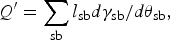 $$Q^{\prime} = \mathop \sum \limits_{{\rm sb}} {l_{{\rm sb}}}d{\gamma _{{\rm sb}}}/d{\theta _{{\rm sb}}},$$
where l sb denotes the boundary length with grain boundary energy γ sb and misorientation angle θ sb across the boundary between the reference subgrain and a neighbouring subgrain sb. For low-angle boundaries, the boundary energy as a function of misorientation angle is calculated with the Read–Shockley equation (Read and Shockley, Reference Read and Shockley1950). For this misorientation angle, the equivalent rotations by crystal symmetry are considered in order to obtain the minimum misorientation θ between two crystallite/subgrains.
Note that Eqn (14) assumes that the torque is calculated with respect to an axis through the centre of mass of the subgrain. If grain rotation is assumed as a viscous process and it is accommodated by either cooperative motion/rearrangement of dislocations in the boundary (Li, Reference Li1962) and/or by boundary and lattice diffusion (Moldovan and others, Reference Moldovan, Wolf and Phillpot2001, Reference Moldovan, Wolf, Phillpot and Haslam2002), M' can be expressed as:
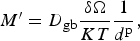 $$M^{\prime} = {D_{{\rm gb}}}\displaystyle{{\delta {\rm \Omega}} \over {KT}}\displaystyle{1 \over {{d^{\rm p}}}},$$
where D gb is the grain boundary self-diffusion, δ the diffusion width of (sub-)grain boundary, Ω is the atomic volume, K the Boltzmann's constant, T is the temperature and d is the (sub-)grain-size. The exponent p varies according to the assumed accommodation process. Results from atomistic simulations and phase-field models by Upmanyu and others (Reference Upmanyu, Srolovitz, Shvindlerman and Gottstein2002) indicated a value of exponent p = 3. The assumption of crystallite geometry as columnar with unit column height includes a geometric factor that raises p to 5. For a temperature of 243 K, the rotational mobility M' is 5.5 × 10⁻⁷ Pa−1 s−1 m−2 (list of values in Table 1).
Explanation of symbols used in text. Values used in the current models are given in parentheses

Recovery is implemented in ELLE using the unconnected nodes layer and assuming that each unode is a potential subgrain. As previously indicated, the goal of this routine is to reduce the intracrystalline heterogeneities by means of local rotation of the crystal lattice at each unode resulting in a decrease of the local misorientation, development of areas of homogenous lattice orientations and the evolution of subgrain boundaries (Borthwick and others, Reference Borthwick, Piazolo, Evans, Griera and Bons2013). Briefly, the process follows the same philosophy as for GBM. However, instead of using trial positions, trial rotations of the lattice are now used. The algorithm starts by choosing a random unode and finding the neighbouring unodes that belong to the same grain. Then, the average misorientation $\widetilde{{{\theta _{\rm i}}}}$
and boundary energy
$\widetilde{{{\theta _{\rm i}}}}$
and boundary energy $\widetilde{{{\gamma _{\rm i}}}}$
between the reference unode i and the neighbour unodes j are calculated.
$\widetilde{{{\gamma _{\rm i}}}}$
between the reference unode i and the neighbour unodes j are calculated.
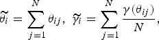 $$\widetilde{{{\theta _i}}} = \mathop \sum \limits_{\,j{\rm = 1}}^N {\theta _{ij}},\; \widetilde{{{\gamma _i}}} = \mathop \sum \limits_{\,j{\rm = 1}}^N \displaystyle{{\gamma ({\theta _{ij}})} \over N},$$
where θ ij is the minimum misorientation angle after taking the symmetry operators into account.
A number of potential rotation axes are initially selected according to the potential specific active slip-system during deformation. During the routine, the predefined crystallographic axes are selected sequentially and a very small angle of rotation is carried out. Then, the new $\widetilde{{{\gamma _i}}}$
is calculated and compared with the initial energy: the crystal orientation of the reference unode is rotated towards the value that results in the maximum reduction in energy. If all trials result in an increase in the energy of the neighbourhood, the crystal orientation at the datum point is left unchanged. A difference to the original approach by Borthwick and others (Reference Borthwick, Piazolo, Evans, Griera and Bons2013), where a constant rotation rate is applied independently of the torque component, the rotation rate is calculated here by using the torque as a driving force according to Eqn (13). To simplify the routine, the boundary length of all datapoints is considered to be equal. This procedure is repeated for each unode in a random order.
$\widetilde{{{\gamma _i}}}$
is calculated and compared with the initial energy: the crystal orientation of the reference unode is rotated towards the value that results in the maximum reduction in energy. If all trials result in an increase in the energy of the neighbourhood, the crystal orientation at the datum point is left unchanged. A difference to the original approach by Borthwick and others (Reference Borthwick, Piazolo, Evans, Griera and Bons2013), where a constant rotation rate is applied independently of the torque component, the rotation rate is calculated here by using the torque as a driving force according to Eqn (13). To simplify the routine, the boundary length of all datapoints is considered to be equal. This procedure is repeated for each unode in a random order.
Finally, dislocation density in the model updated as a change of misorientation angle implies a modification of them following a proportional relationship between both variables.
2.5. Program flow and coupling the viscoplastic FFT code with ELLE
A resolution of 256 × 256 Fourier points (unodes) is used to map lattice orientations, resulting in a unit cell defined by 65,536 discrete nodes. Each unode represents a small area or crystallite with a certain lattice orientation and dislocation density. The lattice orientation is defined by three Euler angles. The FFT module uses these unodes, not the GB network. The data structure of ELLE is fully periodic wrapping: grains touching one side of the model continue on the other size. This feature not only reduces boundary effects, but is a requirement for the FFT code. The shape of grains changes by changing the position of bnodes, either according to the velocity field (deformation) or by GBM. Distances between nodes are kept between 5.5 × 10⁻³ and 2.5 × 10⁻³, the unit distance, by removing double nodes when their neighbours are too close or adding double nodes when two nodes are too far apart. When two triple nodes approach each other within a distance of 2.5 × 10⁻³, a neighbour switch is carried out. Small two- or three-sided grains are removed when they are defined by triple nodes only and their distance becomes <2.5 × 10⁻³, the unit distance.
In ELLE, each process is simulated with a separate module that acts on the data structure (Jessell and others, Reference Jessell, Evans, Barr and Stüwe2001a). Each process is activated sequentially in a loop that represents a small time increment (∆t). The optimal ∆t depends on the process. To avoid using a small ∆t, required by one process, for a computationally expensive process that allows a larger ∆t, processes may be called on a different number of times within each loop. An experimental run (Fig. 3) consists of iterative applications of small increments of 2% of shortening in vertical coaxial compression by viscoplastic deformation (FFT), followed by GBM and recovery. To avoid large steps during simulation of recrystallisation, GBM and recovery are simulated using a sub-loop where both processes are combined using small time increments (∆t/5). This methodology avoids the influence of order in running the recrystallisation processes and increases the stability of the numerical solution. Resolution tests were performed to ensure that the temporal and spatial resolutions are adequate.
Schematic program flow. The initial microstructure is subjected to a closed loop of two alternating processes or modules: viscoplastic deformation (FFT) and DRX. The DRX step itself consists of a number of alternating GBM, and recovery calculations.

Each simulation of coupled deformation and recrystallisation begins with a viscoplastic deformation step. After numerical convergence of the viscoplastic FFT, the new positions of Fourier points are updated using Eqn (17). As Fourier points and unodes in ELLE are equivalent, the position and material properties (i.e. Euler angles, dislocation density) of unodes are directly updated. During transfer information between programs, we assumed that the micromechanical fields are constant during the incremental step. Based on the velocity field, the new locations of bnodes are calculated using a linear inverse weighted interpolation,
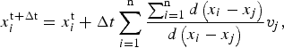 $$x_i^{{\rm t + \Delta t}} = x_i^{\rm t} + \Delta t\mathop \sum \limits_{i{\rm = 1}}^{\rm n} \displaystyle{{\mathop \sum \nolimits_{i{\rm = 1}}^{\rm n} d\left( {{x_i} - {x_j}} \right)} \over {d\left( {{x_i} - {x_j}} \right)}}{v_j},$$
where only the velocity v j from unodes located at a distance d(x i −x j ) below a threshold is taken into account. After an increment of deformation, the unodes no longer define a regular grid and a new regular mesh of Fourier points is required in order to run the next step. A particle-in-cell approach is used to remap all properties from the current configuration to a new regular Fourier grid. In order to avoid unrealistic lattice orientations, Euler angles of new Fourier nodes are not interpolated and they are defined using the lattice orientation of the nearest unode that belongs to the same grain. For the case of viscoplastic materials, as simulated here, the constitutive relations are defined by means of quantities defined in the current configuration only and the approach allows us to run numerical simulations up to high-strains. This approach was verified by Griera and others (Reference Griera2011, Reference Griera2013) using Eshelby's problem (Eshelby, Reference Eshelby1957, Reference Eshelby1959) of deformation of a hard inclusion in a softer matrix.
2.6. Numerical experiment setup
The 20 × 10 cm2 initial microstructure with 3264 grains, each with an initially homogeneous, random lattice orientation (Fig. 1c), was deformed up to 70% of shortening in plane-strain pure shear. Dislocation glide of ice single-crystal was defined by slip on the basal plane {0001}{11–20}, prismatic plane {1–100}{11–20} and the pyramidal systems {11–22}{11–2–3}. This approach is similar to that of other authors (Montagnat and others, Reference Montagnat2013). In the simulations, the ratio of CRSS for non-basal versus basal slip systems was set to A = 20. This value, <A = 60–100 known for Ih ice, was chosen as a compromise between calculation time (dependent on A) and accuracy of the simulations. Tests showed that the effect of increasing A diminishes strongly for A > 10 (Lebensohn and others, Reference Lebensohn, Tomé and Ponte Castañeda2007). A constant stress exponent of n = 3 was set for all slip systems. Grain boundary properties were assumed isotropic, i.e. independent of the lattice orientation of the adjacent grains.
The FFT calculation is numerically the most expensive of all. Each deformation step was thus kept at a constant strain increment during calculation. Different strain-rates were achieved by varying the number of steps, each equal to 20 years, in the recrystallisation loop, giving strain-rates from 1.27 × 10⁻¹² to 3.17 × 10⁻¹¹ s−1 for 1–25 DRX steps per numerical time step, respectively (Table 2). One simulation (Experiment 0) with no DRX is included for reference.
Numerical experiment set-up

2.7. Postprocessing
Crystallographic preferred orientation data are presented as pole figures. Furthermore, LPO data were plotted in inverse pole figures, where the sample x-, y- and z-directions are projected with respect to the crystallographic directions. These data were plotted using the texture analysis software MTEX (http://mtex.googlecode.com) (Bachmann and others, Reference Bachmann, Hielscher and Schaeben2010; Mainprice and others, Reference Mainprice, Hielscher and Schaeben2011) from the orientation distribution function.
The c-axis orientation of the crystal-axis orientation c k can be determined by two angles: the colatitude or tilt angle θ k, and the longitude or azimuth φ k, both in a range [0–2π], considering a reference system RS where the third axis is perpendicular to the xy-plane. c k can expressed as (Durand and others, Reference Durand2006):
 $${c^{\rm k}} = (\cos {\varphi _{\rm k}}\sin {\theta _{\rm k}},{\rm} \sin {\varphi _{\rm k}}\sin {\theta _{\rm k}},{\rm} \cos {\theta _{\rm k}}),$$
The second-order orientation tensor a (2) was used to characterise the c-axis orientation distribution. Following Woodcock (Reference Woodcock1977), a (2) is defined as:
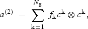 $${a^{\left( 2 \right)\;}} = \; \mathop \sum \limits_{{\rm k = 1}}^{{N_{\rm g}}} {\,f_{\rm k}}{c^{\rm k}} \otimes {c^{\rm k}},$$
where f k is the volume of a grain k from a 2-D section, that is proportional to its measured cross-sectional area A k and the areas containing non-intersecting crystals N g (Gagliardini and others, Reference Gagliardini, Durand and Wang2004). For these simulations, we assume that this volume is proportional to the total number of unodes N p over which the c k is obtained:
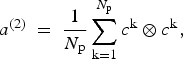 $${a^{\left( 2 \right)\;}} = \; \displaystyle{1 \over {{N_{\rm p}}}}\mathop \sum \limits_{{\rm k = 1}}^{{N_{\rm p}}} {c^{\rm k}} \otimes {c^{\rm k}},$$
assuming that a (2) is symmetric, there is a principal RS R sym in which the second-order orientation tensor is diagonal. Then, we can define a i (2) (i = 1, 2, 3) and e i (i = 1, 2, 3) as the expression of the three eigenvalues and their corresponding eigenvectors, associated with the three base vectors of the R sym. The eigenvectors give the axis direction of the ellipsoid that best fits the density distribution of the grain orientations.
In this study, ice crystal preferred orientation symmetry is expressed as the proportion of point (or single maximum), girdle and random components of the [0001] crystallographic axis (Zaffarana and others, Reference Zaffarana, Tommasi, Vauchez and Grégoire2014). These fabric-type indices were calculated from the three eigenvalues (a 1 (2), a 2 (2), a 3 (2)) as P = a 1 (2) – a 2 (2), G = 2a 2 (2) – 2a 3 (2) and R = 3a 3 (2) (Vollmer, Reference Vollmer1990).
3. RESULTS
3.1. Experiment 0: viscoplastic deformation without recrystallisation
The initial microstructure underwent viscoplastic deformation without DRX. The resulting microstructure has irregular grains, elongated parallel to the stretching direction (i.e. sample y-direction). The deformation is localised into conjugate high-strain bands of strongly elongated grains, with an aspect ratio of approximately 15 : 1, surrounded by low-strain areas or ‘microlithons’ (Passchier and Trouw, Reference Passchier and Trouw2005), where grains are moderately elongated (aspect ratio in the order of 5 : 1) (Fig. 5a). Due to the high differences in CRSS in basal versus non-basal slip systems in ice, the ability to deform a grain depends on the angle ϕ 0 between the c-axis and the compressive stress axis, expressed by the Schmid factor S g (Azuma and Higashi, Reference Azuma and Higashi1985):
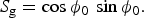 $${S_{\rm g}} = \cos {\phi _{0\;}} \sin {\phi _{0}} .$$
S g is at a maximum when the c-axis is oriented at ϕ 0 = 45° (soft) and at a minimum when ϕ 0 = 0° or 90° (hard) with respect to the compressive axis. The high-strain bands affected soft grains with low resistance to the flow rate (S g). In the absence of recrystallisation all grains are preserved throughout the experiment. Pinching of extremely stretched grains leads to a small increase in the number of grains and concomitant reduction in mean grain size (Table 2). Deformation produced intragranular kinkbands and misorientation, calculated as Kernel Average Misorientation (KAM), was increased in GBs and triple junctions (Fig. 4a and b).
Kernel Average Misorientation (KAM) map for (a) initial, (b) after viscoplastic deformation and (c) after 25 steps of DRX, showing intragranular heterogeneities for grains 1 and 2. Right column shows the polar figures at the three steps of the simulation, shown as lower hemisphere stereographic projections. The KAM is defined as the average misorientation angle of a given unode with all of its neighbour's unodes.

Grain network and c-axis orientation (a–d) and boundary misorientation (e–h) at 70% of shortening for simulations with (a, e) no recrystallisation, (b, f) 1 step, (c, g) 10 steps and (d, h) 25 steps of recrystallisation per deformation step. The original size is double that of the images shown. For better visibility images for Experiments 0 and 1 have been enlarged (2x). Crystal orientations are shown as shortening direction y in crystal reference frame (IPF).

From an initially random c-axis distribution (Fig. 6a), LPO evolved into a cone distribution with an opening angle of 90° at 30% shortening (Fig. 6b). C-axes rotated towards the compression axis. The LPO further evolved into a strong single maximum pattern (Fig. 6c, cone opening angle about 60°). In general, the LPO evolves from a random to a point-maximum distribution, with a small girdle component (Fig. 7). Crystallographic orientations that deviate significantly from the point-maximum are mostly found in low-strain regions (Fig. 5a).
Pole figures of lattice preferred orientation (LPO) for all the simulations performed in this study, showing (a) the initial random distribution, (b) at 30% of shortening, (c) at 70% of shortening. (d) Inverse polar figures of the x-, y- and z-axis of the sample with respect to crystal orientations. Colour bar for polar and inverse figure indicates the multiples of uniform distribution.

Ice LPO symmetry expressed as the proportion of point (or single maximum), girdle and random components for the c-axes <0001>. Different grey values represent simulations with different amounts of DRX: 0, 1, 10 and 25 GBM steps per deformation step.

3.2. Experiments 1, 10, 25: viscoplastic deformation with recrystallisation
Three different ratios between DRX (GBM and recovery processes) and deformation were modelled (1, 10 or 25 steps of DRX per deformation step), to observe the influence of recrystallisation on the structure evolution. The final grain boundary geometry was interlobate with irregular lobate GBs (Fig. 5f and g) as expected for high temperature deformation (Passchier and Trouw, Reference Passchier and Trouw2005). The curved shapes of boundaries indicate the direction of GBM such that regions with high dislocation densities were swept away. Despite the amount of recrystallisation, grains remain elongated and parallel to the stretching direction. The main differences caused by DRX in comparison with Experiment 0 are: (1) larger grains, with lower intracrystalline heterogeneities; (2) a more equidimensional microstructure with smooth boundaries; (3) without localisation bands of strongly elongated grains (Fig. 5b–d).
The mean grain area increased, however not proportionally to the number of GBM steps (Table 2). The final mean grain area is 5.3 and 13.4 times larger in Experiment 10 and Experiment 25 compared with Experiment 1. For a linear increase in grain area with time as expected for NGG one could expect factors of 10 and 25. At 70% strain, 41% of the initial grains disappeared in Experiment 1, and only 11 and 5% of grains survived in Experiment 10 and 25, respectively (Table 2). The recovery process produced high-misorientation areas (>15°), resulting in the development of subgrains in Experiments 10 and 25 (Fig. 5g and h). Subgrain formation is controlled by both viscoplastic deformation and intracrystalline recovery. It is a function of plastic rotation rate gradient, while growth and evolution is controlled by misorientation minimisation simulated by the recovery process. With active DRX, the internal boundary misorientation in general first increased, followed by a reduction when grains start to disappear (grey shading in Fig. 5f and h). Misorientation remained high at GBs and triple junctions after DRX (Fig. 4c).
Although activation of recrystallisation causes a remarkable change in grain boundary microstructure, it does not significantly modify the development of a single maximum distribution of c-axes compared with Experiment 0 (Fig. 5b–d). The single-maximum c-axes LPO at low angles to the shortening direction (parallel to the compression axis) develops at medium strains (Fig. 6b), leading to a strong single maximum at 70% strains (Fig. 6c). With increasing DRX the c-axes maxima develop a small angle with respect to the shortening direction. Figure 7 shows that c-axes LPO evolve quicker than in the case of no DRX and first show a point-to-girdle distribution, followed by a decreasing girdle component. The a-axes distribution shows a stronger effect of DRX with the development of two sets of 3 distinct point maxima (3 axes <11–20> and 3 prism plane normal axes {10–10}), distributed around a girdle in the yz-plane (Fig. 6d).
4. DISCUSSION
We have applied a FFT formulation to model viscoplastic deformation by dislocation glide, together with GBM and recovery processes, in order to simulate the development of the microstructure and LPO in ice. Results of four experiments that represent deformation at different strain-rates were compared. Our approach serves to predict the viscoplastic behaviour of an isotropic polycrystal on the microscopic scale.
4.1. Microstructure evolution
In Experiment 0 (only deformation) there is no grain growth, as GBM (static and dynamic) is not allowed and, therefore, all grains survive (Table 2). A slight increase in total number of grains is observed at the end of the experiment (Table 2) due to splitting by topological changes of the grain network during simulations. Grain growth is clearly observable in Experiments 1, 10 and 25, with the final grain size increasing with number of DRX steps (Fig. 8a). In all experiments the grain-growth rate initially follows that for NGG (i.e. dominated by boundary energy) (k = 0.04 mm2 a−1), followed by a stage of faster growth (Fig. 8c). This effect is stronger at a high-strain-rate (Experiment 1, k = 0.08 mm2 a−1) than at the lowest train-rate (Experiment 25, k = 0.064 mm2 a−1). The difference in the strain stored energy produces higher bulk effective mobilities by increasing the strain-rate. The increase in grain-growth rate is caused by GBM driven by strain energy, which is the strongest at high-strain-rates where recovery has less time to recover internal strains. It should, however, be borne in mind that grain size reduction by polygonisation is not fully implemented in the model.
Average grain area evolution for all experiments with respect to the amount of shortening (a) and (b) aspect ratio evolution during deformation showing in grey lines the vertical shortening. The average grain area increases with time, being the effective mobility, higher in Experiment 1 than in Experiment 10 and 25 compared with the mobility for a NGG experiment (c). The “only NGG curve” (NGG experiment) and “only deformation” curve (Experiment 0) are considered the two extreme cases. Experiment 0 curve in (a) is almost parallel to the shortening axis.

The evolution of grain morphology depends on the ratio between deformation and DRX. Deformation without recrystallisation produces elongated grains, while DRX leads to larger and equidimensional grains. In Experiment 0 the average grain area remains constant during deformation, while aspect ratios of grains range from 5 : 1 in low-strain regions (or microlithons) to 15 : 1 in high-strain localisation bands (Fig. 5e). These low values of grain's aspect ratio highly contrast with the theoretical aspect ratio of 11 at 70% of shortening, which thus cannot be due to the highly intrinsic anisotropy of the ice but due to extensive DRX and associated GBM.
Figure 8b shows the influence of the amount of DRX in the relationship between grain size and grain elongation. When DRX is activated, grain elongation is strongly reduced, even in Experiment 1 where the grain aspect ratio only reaches a value of <3 at 70% shortening (Figs 5b and 8b). Shear localisation is difficult to discern in the microstructure in Experiment 1 and completely masked by DRX and associated GBM in the lower strain-rate experiments (Fig. 5c and d).
In pure ice, GBM inhibits the development of strong grain elongations at natural strain-rates. Very elongated grains are only found in polar ice cores with a very high content of impurities, which reduces GB mobility (Fitzpatrick and others, Reference Fitzpatrick2014). In the Greenland ice core project (GRIP) (central Greenland) and Vostok (east Antartica) ice core, the aspect ratio of grains observed has an average value of about 1.35 (Thorsteinsson and others, Reference Thorsteinsson, Kipfstuhl, Eicken, Johnsen and Fuhrer1995) and 1.5 (Lipenkov and others, Reference Lipenkov, Barkov, Dural and Pimenta1989), respectively. Slightly higher values (average 1.8 to maximum 2.2; unpublished data) were observed in the EPICA Dronning Maud Land (EDML) core (Antarctica). This suggests that DRX in polar ice is at least as important as in our Experiment 25.
When intense DRX (experiments 10 and 25) is activated, intragranular kink bands, developed by folding of the basal plane due to the highly anisotropy of ice crystal, disappear with increasing strain and grains tend to reduce the internal misorientation (Fig. 4). Therefore, DRX reduces the internal misorientation and sweeps away the kink bands produced by deformation. This observation contrasts with experimental observations and previous predictions by numerical simulations where kink bands are preserved (Lebensohn and others, Reference Lebensohn, Brenner, Castelnau and Rollett2008; Montagnat and others, Reference Montagnat, Blackford, Piazolo, Arnaud and Lebensohn2011; Piazolo and others, Reference Piazolo, Montagnat, Grennerat, Moulinec and Wheeler2015), mainly due to the limited shortening and high-strain-rate of the experiments, or because DRX processes were not numerically simulated. In contrast, kink band structures are not observed in polar ice cores. A plausible simple explanation of this is that intragranular recovery relaxes these structures and/or evolves to develop subgrain boundaries.
Heterogeneous distribution of stored strain energy and differences in grain curvature are the driving forces to explain the dynamics of growth/shrinkage of grains during the simulations. A summary of surviving grains is shown in Table 2. The number of grains disappearing during deformation increases with increasing DRX, as a result of grain growth. In general, grains oriented with high Schmid factors (Eqn (21)) (i.e. soft orientations) are expected to deform strongly and increase their internal stored strain energy (Thorsteinsson, Reference Thorsteinsson2002). Therefore, these soft grains are expected to be overgrown by grains with low Schmid factors (i.e. hard orientations). In our experiments, the survival of grains seems to be only weakly dependent on their initial lattice orientation relative to the stress field (S g): only grains oriented with their c-axes parallel to the xy-plane have a slightly enhanced chance of disappearing compared with grains with other orientations (Fig. 9a–c). The initial Schmid factor thus appears to play a minor role in the survival chances of grains, possibly due to the heterogeneous strain distribution within the polycrystal, which is consistent with findings by Thorsteinsson (Reference Thorsteinsson2002). Initial grain size, however, is found to be a primary factor in determining grain-survival chances. As GB energy is a dominant driving force for GBM, grain survival probability is highly correlated with the initial grain size (Fig. 9d). This effect is observable in growth curves (Fig. 8c), where all the experiments follow the NGG curve at the beginning of the simulations.
Initial grain boundary network for Experiment 25, showing (a) Schmid factor (S g) for grains that survive until the end of the experiment. Initial pole figures of (b) all grains, and (c) surviving grains. (d) Initial average grain area distribution and survival rate at the end of Experiment 25. Larger grains have a higher probability of survival, while small grains disappear.

In terms of the numerical model, a larger grain size implies larger regions of homogenous lattice orientation, and therefore, regions where incompatibilities of strain field are expected to be minimised. Therefore, deformation can be distributed more homogenously without developing large strain gradients. In the other extreme, regions of small grains and/or high internal misorientation are associated with high-strain gradients and, therefore, high values of stored strain energy. According to these observations, no correlation between Schmid factor and dislocation density or misorientation values is observed. Although our models are limited because nucleation of new grains, and therefore grain size reduction, was not simulated, our observation can be used to interpret situations where grain coarsening is dominant (e.g. during initial grain coarsening in the upper levels of ice sheets).
4.2. LPO evolution
In all simulations the initially random c-axis orientation distribution of grains is destroyed, and c-axes rotate towards the maximum shortening direction (Figs 5 and 6). This evolution has been observed before in the laboratory experiments by Jacka and Maccagnan (Reference Jacka and Maccagnan1984), where ice samples deformed at −3°C on compression develop circle girdle fabrics around the compression axis (Castelnau and others, Reference Castelnau, Duval, Lebensohn and Canova1996). When DRX is activated the c-axes start to develop an angle with the xy-plane (Fig. 6c and d). The influence of the amount of recrystallisation on the LPO evolution can be observed in Figure 7, where the initial random c-axis orientation distribution is destroyed first, followed by the formation of a combined girdle- and single-maximum fabric and finally tending towards a single maximum pattern. The girdle fabric is most pronounced at a high number of DRX steps, where the random orientations are also destroyed earlier than in experiments with little or no DRX.
In experiments with a large number of recrystallisation steps (Experiments 10 and 25), the a-axes simultaneously rotate, defining a girdle parallel to the xz-plane and maximum parallel to the elongation axis.
The FFT algorithm allows tracking of the relative activity of individual slip systems. Although the LPO development in the different experiments is qualitatively similar (Fig. 7), the amount of DRX causes significant differences in the relative activities of the slip systems (Fig. 10). Basal slip activity decreases with strain, compensated by non-basal slip (Fig. 10). DRX amplifies this behaviour up to a maximum shortening of 70%. The highest amounts of DRX (Experiment 25) exhibit the extreme case: pyramidal slip becomes the most important slip system at ~55% shortening. At higher strains this behaviour may be reverted at differing strain thresholds, indicated by a changing inflection point of the curves in Figure 10.
Relative activity of basal and non-basal slip systems during deformation for all the simulations, calculated from Eqn (2).

The decrease of basal slip activity and its replacement by pyramidal slip has been described before in simulations using a visco-plastic self-consistent approach in uniaxial compression (Castelnau and others, Reference Castelnau, Duval, Lebensohn and Canova1996). However, the rise of pyramidal slip activity with more DRX does not significantly affect the final c-axis distribution, which is similar for all experiments, but instead produces an anisotropic distribution in a- and prism plane normal axes (<11–20> and <10–10>, Fig. 6). Such an anisotropic distribution of a-axes is difficult to observe in ice cores, as full crystal orientation measurements of statistically significant numbers of grains are not standard. In spite of these difficulties, it has been described in one ice core (Miyamoto and others, Reference Miyamoto2005): the deep part of the GRIP ice core (with a strong single-maximum region of c-axis). A significant concentration of a-axis is observed at certain depths. The anisotropy of slip along different crystallographic directions on the basal plane is proposed as a possible explanation (Miyamoto and others, Reference Miyamoto2005). Alternatively, the a-axes distribution could indicate a simple shear component to an overall compressional strain regime: a preferred glide direction in the basal plane will then cause alignment of a-axes along the simple shear direction perpendicular to the c-axes. However, as our simulations were performed in pure shear the first explanation proposed by Miyamoto and others (Reference Miyamoto2005) may hold: if a slip system on a prismatic or/and pyramidal plane is active, a-axes may be able to concentrate gradually with depth (Miyamoto and others, Reference Miyamoto2005).
4.3. Stress evolution
Pure shear simulations are characterised by an initial strain hardening stage followed by a steady state at large strain (Fig. 11d). This hardening is associated with the alignment of c-axes close to the compression axis (Figs 11 and 6). The plateau is reached at lower equivalent stress (Duval and others, Reference Duval, Ashby and Anderman1983) for experiments with more DRX, and is still not reached at 70% shortening in Experiment 1. With more DRX steps the strain hardening stage is contracted, so that simulations reach a steady state at 60% of shortening in Experiment 10 and 50% of shortening in Experiment 25. In Figure 11a–c the evolution of the stress tensors during deformation shows how σ xx and σ yy (extension and compression direction) evolve differently. At the beginning, the out-of-plane deviatoric stress (σ zz) is ~0. As the material hardens, this σ zz increases in absolute magnitude to maintain plane-strain deformation. If we assume that the macroscopic stress exponent can be calculated for the same amount of shortening for simulations at different strain-rates, in order to compare materials of similar states (e.g. similar anisotropy), we can observe an increase of the stress exponent during deformation (Fig. 11e). The exponent increases from the initial n = 3, imposed by the exponent used in the constitutive equation for the individual slip systems (Eqn (2)) to ~3.5 at the end of the experiments. An explanation for this increase of the bulk stress exponent is the DRX-dependent activation of the pyramidal slip system and ensuing strain hardening. It should be noted that the strain hardening is not caused by an imposed hardening law for slip on individual systems, but emerges owing to the development of an LPO, and possibly a shape-preferred orientation (SPO) as well. An SPO with grains elongated perpendicular to the shortening direction has been shown to produce strain hardening (Treagus and Lan, Reference Treagus and Lan2004; Takeda and Griera, Reference Takeda and Griera2006).
Deviatoric stress components evolution during deformation for Experiments (a) 1, (b) 10 and (c) 25. Differential stress versus bulk shortening for Experiments 1, 10 and 25 in (d). Differential stresses in (d) were normalised using the experimental values by Duval and others (Reference Duval, Ashby and Anderman1983), assuming an average grain size of 1 mm, a temperature of −30°C and the correspondent strain-rate for each experiment. (e) Logarithmic relationship between strain-rate and deviatoric stresses for all simulations performed with DRX in (b). The macroscopic stress exponent n resulting from the first step (i.e. 0.02%), 30 and 70% of shortening are indicated.

4.4. Limitations of the model and further processes
In our simulations nucleation, in the sense of formation of new GBs is not implemented yet, but its influence on the microstructure evolution of our simulations has to be considered for interpretation of natural ice (RRX and SIBM-N) (Faria and others, Reference Faria, Weikusat and Azuma2014b). Potential nucleation regions will correspond to areas of heterogeneous intracrystalline deformation and high misorientation. For Experiments 10 and 25, the size of the nucleated grains by RXX (Poirier, Reference Poirier1985; Alley, Reference Alley1992) will be small (as observed by misorientations in Fig. 5g and h) due to the rapidly increasing average grain size. Stored strain energy is not expected to be a strong enough driving force for the growth of the nuclei, due to low intracrystalline heterogeneities, which will produce new grains that are quickly overgrown by the large neighbouring grains. At high rates of GBM, the effect of spontaneous nucleation can therefore be expected to be minor.
We can assume that the possibility of reaching a grain-size steady state depends on the relative amounts of formation of new grains by splitting and nucleation versus GBM (RXX/SIBM), as explained by Faria and others, (Reference Faria, Weikusat and Azuma2014b) using observations described for example, by Alley and others (Reference Alley, Gow and Meese1995). If creation of new grains is controlled by polygonisation (i.e. progressive rotation of subgrains up to development of high misorientation boundaries), we should not expect a strong influence on LPO development, as new grains have lattice orientations that are close to those of their parent grains. However, the numerical implementation of the development of proper high-angle GBs out of tilt walls would reduce both the grain size and elongation compared with the results presented here.
Laboratory creep deformation experiments show a hardening process with a peak strength at a few percentage of strain, followed by a steady state at 10–20%, in either uniaxial compression or simple shear experiments (e.g. Treverrow and others, Reference Treverrow, Budd, Jacka and Warner2012). Our results differ from this evolution, in that steady state creep is not yet reached at 70% of shortening. Even though our simulations have been performed at constant strain-rate and cannot be directly compared with models with three creep regimes, we can hypothesise that this difference could be caused by the nucleation effect on the microstructure, where a steady state is associated with an equilibrium grain size (Jacka and Li, Reference Jacka and Li1994). When this steady state is reached depends on the equilibrium grain size, relative to the starting grain size and the relative roles of nucleation and polygonisation in controlling the steady state. At the high-strain-rates in experiments and, therefore, relatively slow GBM, nucleation probably plays a larger role than it would do in nature at much lower strain-rates. The absence of nucleation in the current simulations may thus limit their applicability to experimental strain-rates, but not necessarily to natural ones.
Other deformation mechanisms apart from dislocation glide can potentially be active, such as diffusion creep or grain boundary sliding for ice (Duval and others, Reference Duval, Arnaud, Brissaud, Montagnat and de La Chapelle2000; Goldsby and Kohlstedt, Reference Goldsby and Kohlstedt2001). As ice in ice sheets generally deforms at rather low-strain-rates, diffusion as an accommodating process cannot be ruled out completely when the grain size is small. However, microstructural evidence for this is scarce, whereas there is abundant evidence for dislocation activity (Faria and others, Reference Faria, Weikusat and Azuma2014a). Although the grain size at the beginning of our experiments is small, grain growth makes the assumption of dislocation glide as the dominant deformation mechanism increasingly valid, at least to a first-order.
Spatial resolution of the unodes grid has an influence on the distribution of the predicted strain-rate and stress fields, and therefore has a potential impact on subgrain development inside grains. An increase of the resolution provides more degrees of freedom to adjust local gradients and an improved resolution of intracrystalline heterogeneities. Figure 12 shows a comparison of the predicted misorientation maps for models with 256 × 256 and 512 × 512 unodes. In general, a higher-resolution grid produces sharper and better-defined subgrain boundaries than lower resolution models where heterogeneities are more distributed. Although smaller subgrain bands are visible in the higher-resolution model, both models show qualitatively very similar grain and subgrain sizes. Most subgrains are located near triple junctions and high-angle GBs, where problems maintaining the strain compatibility arise. This observation indicates that subgrain sizes and shapes inside grains are primarily controlled by the local crystallographic orientation and size of the grain and the local evolution of the neighbouring grains, but also clearly by the recrystallisation processes as observed in experiments with more DRX (see Fig. 5). The potential effects that the coupling between viscoplastic deformation and recrystallisation processes may have on length scale and evolution of subgrains need to be addressed in future studies
Comparison of the predicted misorientation maps for models with (a) 256 and (b) 512 resolution unode grids. A higher resolution produces better defined subgrain boundaries than lower resolution, where heterogeneities are more distributed.

4.5. Implications on interpretation of natural polar ice microstructures
Experiment 0 is an end-member simulation, in the sense that ice at high homologous temperatures (~0.7 to 1) on Earth will not deform without a significant contribution from recrystallisation. This experiment illustrates the effect of formation mechanisms of LPOs on polycrystals of highly anisotropic ice. Dislocation glide, preferably along basal planes, leads to continuous rotation of crystals towards the bulk compression axis. LPOs are typically the most acknowledged microstructural feature in observations in ice cores and experiments (e.g. Rigsby, Reference Rigsby1951; Thorsteinsson and others, Reference Thorsteinsson, Kipfstuhl, Eicken, Johnsen and Fuhrer1995; Azuma and others, Reference Azuma1999; Wang and others, Reference Wang, Kipfstuhl, Azuma, Thorsteinsson and Miller2003; DiPrinzio and others, Reference DiPrinzio2005; Treverrow and others, Reference Treverrow, Budd, Jacka and Warner2012; Fitzpatrick and others, Reference Fitzpatrick2014; Montagnat and others, Reference Montagnat2014 more refs in Faria and others, Reference Faria, Weikusat and Azuma2014a). The strains reached in the simulations (up 70% shortening) nominally correspond to ice sheet depths down to ~1000 m (e.g. Huybrechts and others, Reference Huybrechts, Rybak, Pattyn, Ruth and Steinhage2007). It is roughly at this depth that a change is observed from weak c-axes LPO to strong LPOs (Faria and others, Reference Faria, Kipfstuhl and Lambrecht2014c). Strong LPO development, thus sets later in ice sheets than in our simulations. It remains to be tested, whether this is because nucleation and polygonisation are not yet fully implemented in our model. The simulations do, however, indicate that GBM is not the cause for this, as LPO-development is very similar with (Experiments 1, 10 and 25) and without GBM (Experiment 0). This is in accordance with the observations in ice cores that LPO is continuously developing with depth while other RX measures (grain shape, subgrain boundary density; Weikusat and others, Reference Weikusat, Kipfstuhl, Faria, Azuma and Miyamoto2009; Fitzpatrick and others, Reference Fitzpatrick2014) do not change systematically with depth.
Recrystallisation is the cause of dynamic grain growth (DGG) in natural ice, usually observed in clean interglacial ice cores (e.g. Faria and others, Reference Faria, Kipfstuhl and Lambrecht2014c). Experiment 0 (Fig. 8a and b) microstructure differs significantly from natural polar ice microstructures, which emphasises the necessity to include recrystallisation processes in consideration of deformation by dislocation glide. Particularly interesting is the question concerning the dominance of deformation versus recrystallisation, which was investigated in Experiments 1, 10 and 25. Grain growth occurs when DRX is activated. Although DGG is not proportional to the amount of GBM, grain size and grain elongation depend on the amount of DRX (Fig. 8b).
The GBM module includes static and dynamic driving forces, which determine the motion of boundaries according to the local energy field from grain boundary curvature and the difference in dislocation density (stored strain energy) across the grain boundary. Previous authors have mentioned that a difference in strain between the considered grains and bulk values is needed to model the LPO evolution in ice (Van der Veen and Whillans, Reference Van der Veen and Whillans1994); however the strictly local energy consideration of our simulations is necessary for a realistic GBM, as grain boundaries do not ‘see’ far into the neighbouring grain, as concluded from data on ice core microstructures (Weikusat and others, Reference Weikusat, Kipfstuhl, Faria, Azuma and Miyamoto2009) and creep deformation samples (Hamann and others, Reference Hamann, Weikusat, Azuma and Kipfstuhl2007). Local driving forces for GBM lead to increasing grain growth with increasing amounts of RX, which confirms the concept that DGG accounts for ice grain size evolution (Faria and others, Reference Faria, Weikusat and Azuma2014b). All microstructural studies on polar ice cores so far report certain amounts of grain growth with depth, thus time and deformation – at least as long as we observe similar types of ice (e.g. ‘clean’ interglacial ice) (e.g. Faria and others, Reference Faria, Weikusat and Azuma2014a and references therein). However, nucleation and formation of new GBs are not yet implemented into the suite of simulations presented here and will change the grain size evolution again. Our model is so far able to simulate grain size evolution in the grain growth field of the recrystallisation diagram of Faria and others, (Reference Faria, Weikusat and Azuma2014b) (below the attractor surface Dss).
5. CONCLUSIONS
Observations of microstructure and LPO evolution during numerical simulations at different strain-rates have been presented, providing new information about the influence of recrystallisation during deformation. DRX can significantly increase grain size, avoiding elongation of grains and masking the deformation and strain localisation. DRX does not modify the c-axes LPO evolution, which in all cases is oriented parallel to the shortening direction. However, in experiments at low-strain-rates, the a-axes rotate towards the maximum elongation axis simultaneously. The anisotropic distribution of a-axes is related to the increment of activity of non-basal slip systems. Although GBM is driven by stored strain and boundary energy reduction, the grains’ survival probability is highly related to the initial grain size, and only slightly related to the crystal orientation with respect to the flow rate. Grain growth in experiments at high-strain-rate is faster than in experiments performed at low-strain-rate, due to the stored strain energy.
ACKNOWLEDGEMENTS
We thank Daniela Jansen for discussions and ideas. We thank all the members of the ELLE development group, in particular Sandra Piazolo and Verity Borthwick for their contributions to the simulation code. The study was funded by HGF (VH-NG-802). We thank the editor and two anonymous reviewers for their critical, but very helpful comments and corrections.


 Open access