
1.1 Basics of Visible Light and Primary Colours
Visible light is electromagnetic radiation with wavelengths falling within a narrow band from about 390 nm to 700 nm as shown in Figure 1.1. This band of wavelengths corresponds to the frequency range from about 430 THz to 770 THz [Reference Simpson1]. Light emitted from the Sun comes from the radiation released when the electrons move from higher orbits to a lower one in a hydrogen atom as shown in Figure 1.2. Red, blue and green lights emitted from the hydrogen atoms constitute the three primary colours that form the basics of chromaticity. As shown in the CIE 1931 Colour Space Chromaticity diagram in Figure 1.3, a range of colours including a central region of white colour can be formed by mixing of the three primary colours.
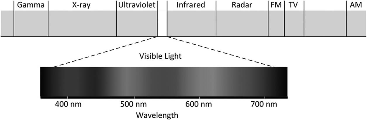
Figure 1.1 Spectrum of electromagnetic radiation


To create white LED devices, different manufacturers have their own binning systems to classify different colour temperatures of ‘white colour’. Some examples are shown in Figure 1.4. The wide variety of binning systems among different LED device manufacturers is a major challenge in LED system designs because it is difficult to control the colour temperature unless some form of closed-loop colour control or colour mixing technique is applied to keep the colour temperature at a targeted value within a certain tolerance acceptable to human perception.
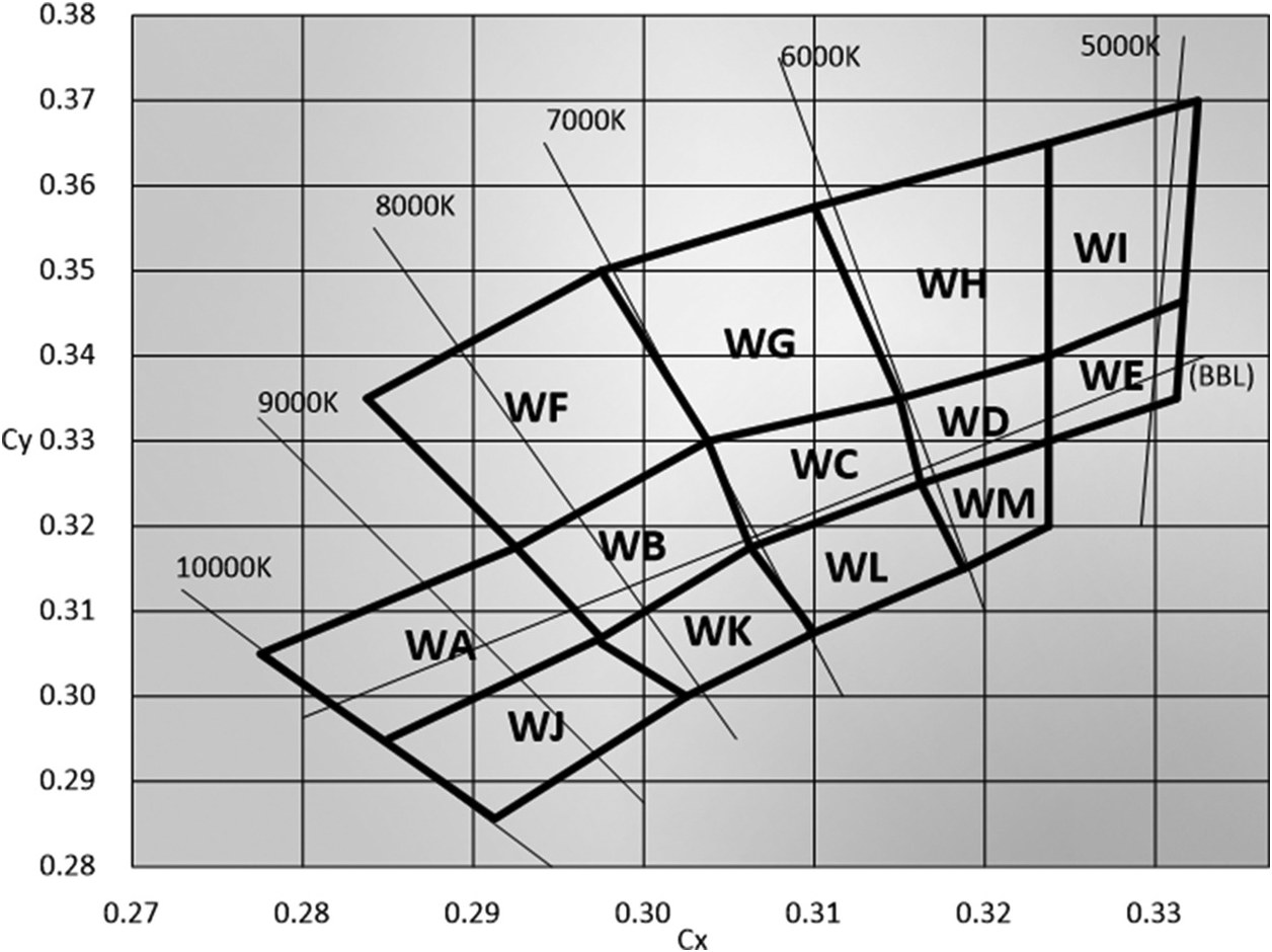
Figure 1.4 An example of a binning system WA–WM for white LED devices
1.2 Light Emission in Traditional Light Sources and LEDs
Traditional light bulbs generate light by incandescence, which means that light is emitted by a solid that has been heated until it glows. For incandescent lamps, the solid is normally the tungsten filament. Low-pressure discharge lamps such as fluorescent lamps emit light through fluorescence, meaning that light is emitted by a substance that has absorbed light or other radiation. The high electrical potential difference between the heated electrodes of a fluorescent lamp causes electrons to accelerate in the low-pressure gaseous mixture inside the fluorescent tube. When the electrons hit the mercury vapour molecules, ultraviolet (UV) light is emitted [Reference Simpson1]. The UV light shines on the tri-color phosphor coating on the inner surface of the tube, which emit white light. The colour temperature of the light is determined by the composition of the tri-color phosphor coating. High-intensity discharge (HID) lamps operate under a different principle. The tube is filled with both gas and metal salts under a pressure higher than atmospheric pressure. The gas facilitates striking of an arc. Once the arc is established, it heats and vaporizes the salts, forming a plasma arc which increases the light intensity. The arc temperature can reach a few thousands degrees [Reference Waymouth2].
The red LEDs developed in the early 1960s did not have sufficient luminous efficacy for general public lighting applications. During the period 1960–1980, LEDs were primarily used in display and signalling applications. The availability of high-brightness blue LEDs in the 1990s has however changed the landscape of LED usage [Reference Fred Schubert3]. In general, white LEDs can be based on several approaches, as indicated in Figure 1.5. The first approach is to use blue LEDs and yellow phosphor. From Figure 1.3, it can be seen that mixing blue and yellow colours gives a white colour. In principle, blue LEDs can work with green and red phosphors to provide the three primary colours resulting in white light. Or red, blue and green LEDs can be used together to generate white light. Among the three approaches, the first one is the most common and efficient in terms of the luminous efficacy (i.e. lumen/watt).
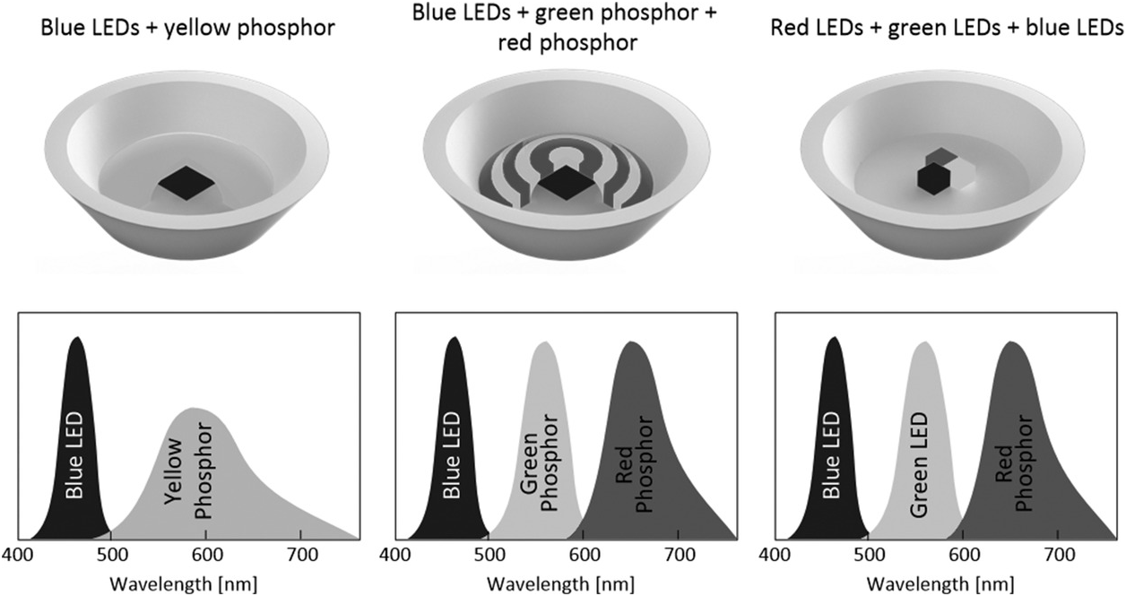
Figure 1.5 Three common approaches that produce white LEDs
1.3 Heat Loss Mechanisms of Traditional Light Sources and LEDs
Unlike incandescent lamps and discharge lamps, LEDs are semiconductor devices, which have relatively low melting points. Table 1.1 summarizes the heat loss mechanisms of various light sources. Incandescent and high-intensity discharge (HID) lamps lose their heat primarily through radiation, while fluorescent lamps lose heat through both radiation and convection. LED devices, however, require conduction to transfer their heat in order to remain at a temperature below their safe thermal limits. This major difference implies that thermal management is critical for LED system design. In LED technology, light emission and heat are ‘enemies’. The luminous efficacy (lumen/watt) of a high-brightness LED decreases as the junction temperature increases. Therefore, a good thermal design not only keeps LED devices within their safe thermal limits, it also maximizes the light output. The photo-electro-thermal (PET) theory introduced in this book can be used as a design tool to optimize an LED system design.
Table 1.1 Comparison of heat loss mechanisms of light sources
| Light source | Luminous efficacy, lm/W | Heat loss by radiation, % | Heat loss by convection, % | Heat loss by conduction, % |
|---|---|---|---|---|
| Incandescent | 10–20 | >90 | <5 | <5 |
| Fluorescent | 75–100 | 40 | 40 | 20 |
| HID | 100–120 | >90 | <5 | <5 |
| LED | 100+ | <5 | <5 | >90 |
1.4 LED Structures and their Thermal Equivalent Models
Figure 1.6 shows a cross-sectional diagram of an LED device. The LED device should be mounted on a heatsink so that the heat generated in the LED device can be transferred out of the LED wafer through the heatsink to the ambient surroundings. In practice, a group of LED devices may be mounted on the same heatsink as shown in Figure 1.7. It is therefore necessary to develop an electro-thermal model for an LED system comprising one or more LED devices, so that optimal thermal design can be achieved.
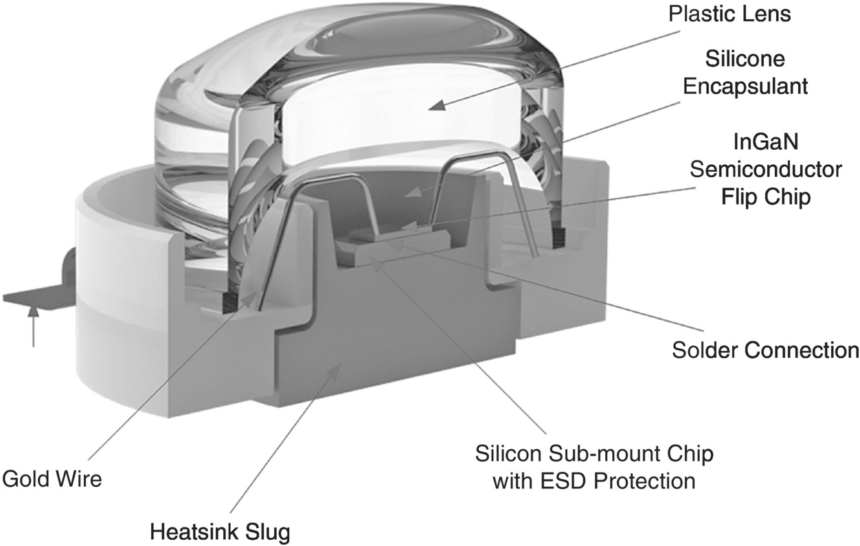
Figure 1.6 A cross-sectional diagram of a high-brightness LED package
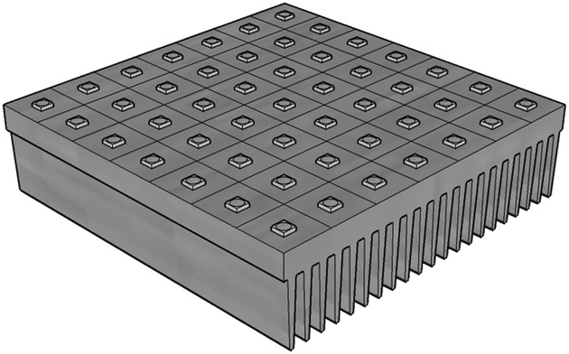
Figure 1.7 A diagram of an array of LED devices mounted on the same heatsink
Under steady-state conditions, the basic equation of heat transfer is:
where Pheat is the power dissipated as heat, hθ is the heat transfer coefficient, Aθ is the cross-sectional area of the heat transfer and ΔT is the temperature difference between two points or regions. The thermal model can find an analogy in an electrical concept in the form of Ohm’s law, as shown in Table 1.2, where V1 and V2 are voltages at point 1 and point 2, respectively, in an electrical circuit; T1 and T2 are temperatures at point 1 and point 2, respectively, in a mechanical system; σ is the conductivity of the current path with conducting area A.
Table 1.2 Comparison of the electrical and thermal models
| Electrical | Thermal | ||
|---|---|---|---|
| Voltage difference | ΔV = V1 − V2 | Temperature difference | ΔT = T1 − T2 |
| Current |  | Heat flow |  |
| Electrical resistance |  | Thermal resistance |  |
For the high-power LED device package in Figure 1.6, the heat flow equation is:
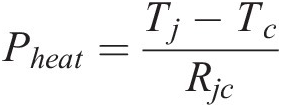 (1.2)
(1.2)where Pheat is the average power dissipation of the power device, Tj is the junction temperature of the LED wafer, Tc is the case temperature and Rjc is the junction-to-case thermal resistance of the LED package [Reference Williams4].
For an LED package mounted on a heatsink, the thermal equivalent circuit is shown in Figure 1.8, where Rch is the thermal resistance of a thin layer of thermal paste or a thin layer of thermally conductive insulator (that electrically insulates the LED package from the heatsink), Rhs is the thermal resistance of the heatsink, Rca is the thermal resistance of the heat flow path from the case of the LED package directly to ambient and Ta is the ambient temperature. In practice, the thermal resistance Rch is much smaller than Rjc and the heat flow of the LED package through conduction is much higher than through radiation and convection (i.e. Rca is very large); therefore the thermal equivalent model can be simplified to the one shown in Figure 1.9. This simple model will be expanded to cover a group of LED packages mounted on the same heatsink in Chapter 2. For more accurate modelling including that of the lateral heat flow within the heatsink, a more sophisticated LED array model will be discussed in Chapter 6.

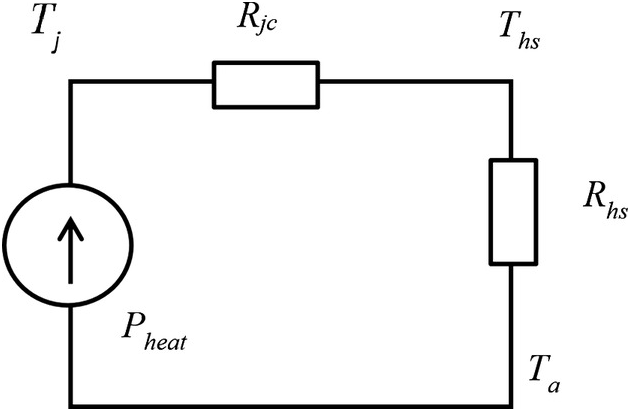
Figure 1.9 A simplified thermal equivalent model of an LED package mounted on a heatsink


