Refine search
Actions for selected content:
2106 results in Aerospace engineering
Chapter 12 - Offshore Wind Power: Overview
-
- Book:
- Wind Turbines
- Published online:
- 24 January 2025
- Print publication:
- 19 December 2024, pp 303-350
-
- Chapter
- Export citation
Chapter 13 - Offshore Wind Foundations
-
- Book:
- Wind Turbines
- Published online:
- 24 January 2025
- Print publication:
- 19 December 2024, pp 351-389
-
- Chapter
- Export citation
Chapter 2 - The Wind and Its Characteristics
-
- Book:
- Wind Turbines
- Published online:
- 24 January 2025
- Print publication:
- 19 December 2024, pp 13-32
-
- Chapter
- Export citation
Chapter 8 - Rotor Blade Technology
-
- Book:
- Wind Turbines
- Published online:
- 24 January 2025
- Print publication:
- 19 December 2024, pp 177-213
-
- Chapter
- Export citation
Chapter 1 - Introduction
-
- Book:
- Wind Turbines
- Published online:
- 24 January 2025
- Print publication:
- 19 December 2024, pp 1-12
-
- Chapter
- Export citation
Chapter 9 - Siting and Installation
-
- Book:
- Wind Turbines
- Published online:
- 24 January 2025
- Print publication:
- 19 December 2024, pp 214-247
-
- Chapter
- Export citation
Chapter 10 - Planning and Environment
-
- Book:
- Wind Turbines
- Published online:
- 24 January 2025
- Print publication:
- 19 December 2024, pp 248-273
-
- Chapter
- Export citation
Preface to the First Edition
-
- Book:
- Wind Turbines
- Published online:
- 24 January 2025
- Print publication:
- 19 December 2024, pp xv-xvii
-
- Chapter
- Export citation
References
-
- Book:
- Wind Turbines
- Published online:
- 24 January 2025
- Print publication:
- 19 December 2024, pp 410-428
-
- Chapter
- Export citation
Copyright page
-
- Book:
- Wind Turbines
- Published online:
- 24 January 2025
- Print publication:
- 19 December 2024, pp iv-iv
-
- Chapter
- Export citation
Chapter 3 - Aerodynamic Theory
-
- Book:
- Wind Turbines
- Published online:
- 24 January 2025
- Print publication:
- 19 December 2024, pp 33-64
-
- Chapter
- Export citation
Chapter 4 - Rotor Design and Performance
-
- Book:
- Wind Turbines
- Published online:
- 24 January 2025
- Print publication:
- 19 December 2024, pp 65-87
-
- Chapter
- Export citation
Chapter 5 - Electrical Aspects
-
- Book:
- Wind Turbines
- Published online:
- 24 January 2025
- Print publication:
- 19 December 2024, pp 88-117
-
- Chapter
- Export citation
Contents
-
- Book:
- Wind Turbines
- Published online:
- 24 January 2025
- Print publication:
- 19 December 2024, pp v-xii
-
- Chapter
- Export citation
Preface to the Second Edition
-
- Book:
- Wind Turbines
- Published online:
- 24 January 2025
- Print publication:
- 19 December 2024, pp xiii-xiv
-
- Chapter
- Export citation
Index
-
- Book:
- Wind Turbines
- Published online:
- 24 January 2025
- Print publication:
- 19 December 2024, pp 429-434
-
- Chapter
- Export citation
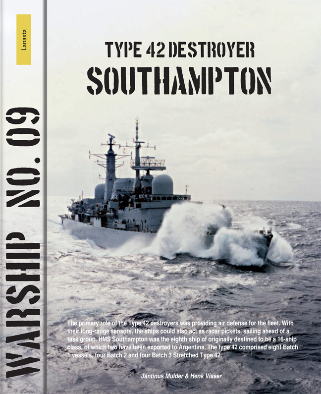
Type 42 Destroyer Southampton
-
- Published by:
- Amsterdam University Press
- Published online:
- 27 March 2024
- Print publication:
- 29 August 2019
-
- Book
- Export citation

Frigate HMS Leander
-
- Published by:
- Amsterdam University Press
- Published online:
- 27 March 2024
- Print publication:
- 28 November 2014
-
- Book
- Export citation

PCE 1604 Series, Frigate Panter
-
- Published by:
- Amsterdam University Press
- Published online:
- 27 March 2024
- Print publication:
- 08 January 2021
-
- Book
- Export citation

CW-21 Interceptor
-
- Published by:
- Amsterdam University Press
- Published online:
- 27 March 2024
- Print publication:
- 10 February 2023
-
- Book
- Export citation
