

Introduction
In mechanical industries, the widespread use of Computer-Aided Design tools has produced large data sets of product models. In this context, the possibility of easily retrieving and then reusing/modifying existing CAD models would be of paramount importance to speed up the development of new products. To this aim in the last decades, PDM (Product Data Management) systems have been introduced in companies for the organization and documentation of their legacy product data. Models can be therefore retrieved according to the adopted organization and metadata specified for describing parts and assemblies. Thus, the possibilities of retrieving elements are strongly dependent on the information assigned by designers and not on the actual content of the models. This can be a big limitation, also considering that not all the companies adopt PDM systems and that often PDM capabilities are only partially exploited. In addition, legacy models produced before the introduction of PDM systems are often archived in the file system without being properly documented and are thus difficult to retrieve. To overcome these limits, shape-based retrieval methods have been investigated in the research community (Cardone et al., Reference Cardone, Gupta and Karnik2003; Bustos et al., Reference Bustos, Keim, Saupe, Schreck and Vranić2005; Iyer et al., Reference Iyer, Jayanti, Lou, Kalyanaraman and Ramani2005; Tangelder and Veltkamp, Reference Tangelder and Veltkamp2008) and some commercial tools are now emerging. These systems generally allow the search for 3D models similar to a given query object formed by a single part. Even if mechanical products are generally formed by several components, only a few methods are addressing the retrieval of assemblies (Deshmukh et al., Reference Deshmukh, Banerjee, Gupta and Sriram2008; Chen et al., Reference Chen, Gao, Guo and Bai2012; Hu et al., Reference Hu, Wang, Yong and Paul2013; Lupinetti et al, Reference Lupinetti, Giannini, Monti and Pernot2018). Dealing with assemblies introduces additional problems related to component organization, normally not explicitly encoded in the model, as well as to component simplification, which frequently occurs when components are acquired from a third party. While most of the research proposed in the literature is mainly focusing on process-oriented classification (e.g. similar fabrication methods) or on the geometric similarity of parts and assemblies; retrieval capabilities more oriented on the purpose of the part or of the implemented mechanisms in the model would be important. A fully automated functional classification of parts based only on their shape is almost impossible since parts apparently identical can have a different usage and the same functions may be performed by parts with a different shape.
Understanding the functionality of a part or of a component in an assembly requires reasoning not only on the shape of its elements but also on its usage within the product. In fact, on the one hand, simplified parts with similar shapes may suit to perform different functionalities, which can be discerned by their usage context, that is, how the parts are embedded in the assembly model. On the other hand, even if a functional set can be obtained with different supplementary parts organized in diverse ways, some components and arrangements recur constantly. Therefore, engineering knowledge on functional sets can provide useful indications for the component classification and therefore for the identification of specific mechanisms. For instance, functional sets whose task is the transformation of the input motion generally include axes on which gears, spacers, and bearings are inserted. The occurrences of this set of parts are a good indicator of the presence of that mechanism type. Indeed, the identification of the assembly components potentially belonging to these classes (i.e. axis, gears, spacers, and bearings) may greatly simplify the mechanism recognition in large assembly models. Based on these considerations, we have implemented this multi-step part classification approach in our system for the retrieval of assembly models (Lupinetti et al., Reference Lupinetti, Giannini, Monti and Pernot2018). Two specific modules have been developed: the first assigns a category to each part according to only to its shape characteristics; then exploiting engineering knowledge, the second module assesses and, if necessary, corrects the initial shape-based classification by analyzing the context of use of the part in the assembly with the ultimate objective of identifying components representing specific functional sets. Details on the context-based revision of the shape-based classification can be found in Lupinetti et al. (Reference Lupinetti, Giannini, Monti and Philippe2017). In this paper, we focus on the description of the methodology and process we followed for the definition and implementation of the first module: the shape-based classification of assembly parts.
Existing research for the classification of mechanical parts includes algorithms that work with various shape descriptors based on projected profiles, feature extraction, and shape related functions. Anyhow, it is recognized that there is not a single descriptor that performs well over all the various types of shapes. Therefore, we investigated the capabilities offered by combining shape descriptors under the umbrella of a machine learning procedure aiming at classifying parts according to their functionality even when the shape of the parts is oversimplified.
The paper is organized as follows. In the section ‘Problem specification and related works’, we give the statement of the problem that we face in this paper and a brief overview of the related existing methods. The section ‘Our approach for mechanical part classification’ briefly introduces the proposed approach for the multi-step classification of parts in assembly models. The section ‘Proposed solution’ contains the details of our solution for shape-based classification of parts, the experimental evaluations, and the results. Finally, summary and conclusions are given in the section ‘Summary and conclusions’.
Problem specification and related works
Our research aims to provide an automated classifier able to associate a specific category to 3D models of mechanical components. Considering the progress in several different areas such as 3D model classification and machine learning, the problem we intend to address is: “given a multi-class dataset of mechanical parts, represented by their 3D model, define a machine learning-based solution for the automated classification of its entries”.
The classification problem can be thought of as a specific statement of a more general situation that is the matching and the retrieval of 3D CAD data. Various methods have been presented in the literature for 3D object retrieval possibly including more functional or application aspects, for example, Cardone et al. (Reference Cardone, Gupta, Deshmukh and Karnik2006); here we only report the most pertinent works focusing on part classification. Among them, Marini et al. (Reference Marini, Spagnuolo and Falcidieno2007) propose a technique to define 3D shape prototypes for the classification of 3D content. The defined shape-prototype summarizes the most relevant features of the members of a class. In this method, each member of a class is represented by a structural descriptor encoded as an attributed graph. The prototype is obtained by applying graph-transformation techniques among the shape descriptors associated with the members of the class. The method better applies to discern macro categories of objects and does not well fit for mechanical parts with small differences.
Philipp-Foliguet et al. (Reference Philipp-Foliguet, Jordan, Najman and Cousty2011) address the classification of artworks, in particular, it focuses on the identification and classification of the Venus from Mother-Divinity categories, whose characteristics strongly differ from our types of objects.
In the mechanical field, Jayanti et al. (Reference Jayanti, Kalyanaraman and Ramani2009) provide a comparison of the application of clustering methods to 3D models for the navigation of 3D repositories. Additional works address the categorization of parts according to specific design processes. Among them, Pernot et al. (Reference Pernot, Giannini and Petton2015) tackle the problem of categorizing products in terms of characteristics that might affect the simplification of parts for the Finite Element Analysis (FEA). To this aim, using a combination of shape descriptors, parts are classified in terms of three categories: thin parts, parts with thin portions and normal. Unfortunately, this classification is too rough for discerning on the effective shape of parts. Still, in the context of FEA model preparation, Shalwan et al. (2014) identify functional components in assemblies, such as cap-screws, tubular rivets, and gears. This approach assumes that all the parts are fully detailed and it strongly relies on the geometric interferences between components and on reasoning capabilities on structured formalized engineering knowledge (in the form of ontology). Thus, it is not able to provide any category indication either for single parts not in an assembly and for parts in an assembly with the simplified shape. Manufacturing features were used for similarity assessment and classification by Cicirello and Regli (Reference Cicirello and Regli2002). The main drawbacks of using features lie in the need for a feature recognition process, which provides results very sensitive to interactions among features, and does not consider the overall shape of the object.
Machine learning and deep learning applications for 3D CAD models classification have been reported too. In Ip et al. (Reference Ip, Regli, Sieger and Shokoufandeh2003) the authors define a new feature space based on metrics features (inner, outer, and mixed distances) over which they approach the classification of solid models using learning techniques (decision tree and reinforcement learning), that allow the automated categorization of wheels, sockets, and housing models. In Yiu Ip and Regli (Reference Yiu Ip and Regli2005), the authors present another approach to automate the classification of CAD models with machine learning techniques. More recently, in Qin et al. (Reference Qin, Li, Gao, Yang and Chen2014) the authors present an automated 3D CAD model classification approach based on the deep learning technique. The classifier is able to mimic the main phases of a manual classification process in which an engineer usually opens a 3D model with CAD software, rotates it on the screen, observes it from desirable viewing angles, and then synthesizes those viewing images to obtain the semantic category. In Wang et al. (Reference Wang, Kang and Li2015), the authors propose a novel solution for the retrieval of 3D CAD objects by using a convolutional neural network that processes information gained from sketch-based and shape-based methods.
Our approach for mechanical part classification
As previously stated, we intend to associate mechanical parts with the corresponding category. While knowing that the shape is a distinguishing aspect of parts, a classification based only on shape-related characteristics is impossible: similar shapes can satisfy different functional objectives and moreover parts can be simplified when inserted in assemblies; therefore, we propose the two-phase approach illustrated in Figure 1.
The proposed part classification process.
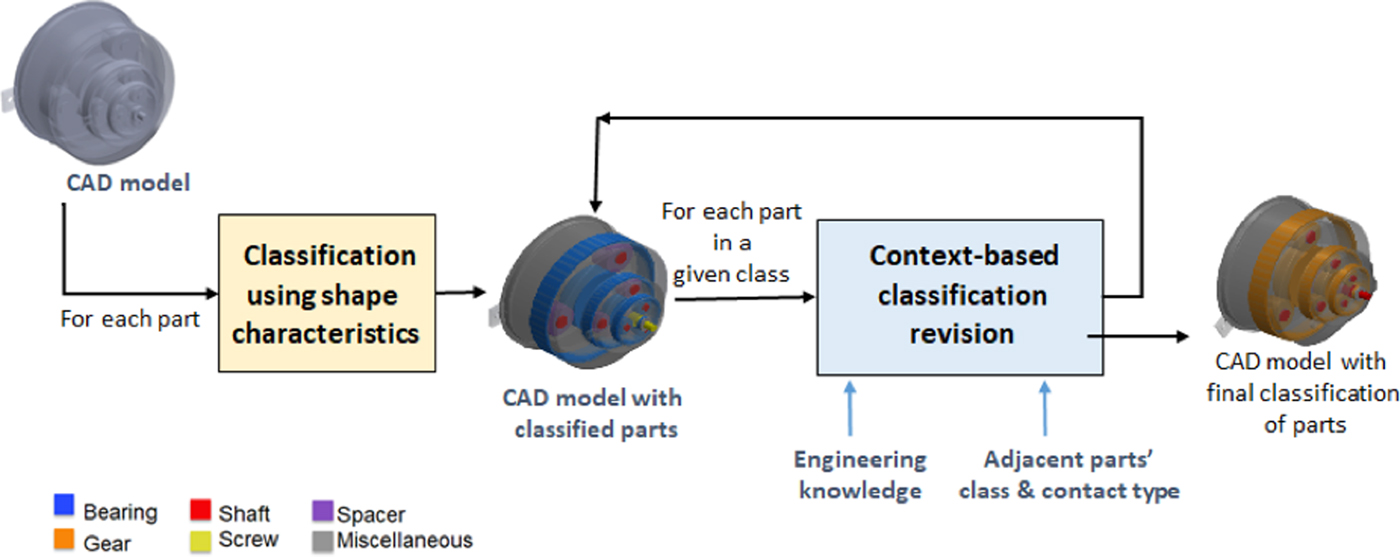
The first phase is applied to single parts to associate the most pertinent category based on its shape characteristics. The second phase can only be applied to parts inserted in an assembly. In this phase, we analyze parts according to their category to assess the correctness of the classification. The evaluation uses engineering knowledge about the generally present interactions between components in specific mechanisms. The rationale behind is that a specific mechanical component may perform its function within a functional set if it is positioned according to specific conditions with respect to certain classes of components. Hence, to determine if a component effectively belongs to the assigned class we check its relations with the other components of the assembly, for example, with which types of components/parts the examined part interacts. Parts are analyzed class-by-class according to a given order. If a part does not respect the expected condition, it is reclassified as the not yet analyzed most promising category. Details on this phase can be found in Lupinetti et al. (Reference Lupinetti, Giannini, Monti and Philippe2017). Here the rest of the paper is focusing on the methods and process we applied to realize the first phase using a machine learning approach.
Proposed solution
Our solution is obtained on top of a data analysis process. Before reporting on the details of our solution for the development of the first classification module, let us recall that a general data analysis process is based on the following steps (Yandel, Reference Yandell1997):
• Data Acquisition:
(i) Obtaining the data
(ii) Visual investigation of the data space
(iii) Cleaning the data
• Feature Extraction and Feature Analysis:
(i) Feature extraction
(ii) Exploratory analysis of the feature space
(iii) Pre-processing the feature space
(iv) Feature selection
(v) Feature reduction
• Modeling the classifier:
(i) Modeling of the classifier system
(ii) Validation of the model
(iii) Visualization of the model
(iv) Visualization and interpretation of the results
• Results analysis:
(i) Deployment of the model
(ii) Visualization of the results
Note that the visualization action is performed in each step in order to highlight new insights about the underlying patterns and relationships contained within the data.
The heat map is one of the most useful tools for visualizing pair-wise distances among features. This highlights modularity (clusters) and other characteristics of the feature space (e.g. linear separation, etc…) (Fayya et al., Reference Fayya, Wierse and Grinstein2002).
Data acquisition
The application of learning techniques for detecting the most important parameters and values for the classification strongly relies on the training set. Different classifications can be applied to the same object depending on the purposes. In Jayanti et al. (Reference Jayanti, Kalyanaraman, Iyer and Ramani2006) the authors proposed a benchmark database (https://engineering.purdue.edu/cdesign/wp/?page_id=1386) for evaluating shape-based search methods relevant to the mechanical engineering domain. To this aim, the organization of the dataset in classes is performed according to the main shape characteristics of the parts to verify the capabilities of the various shape descriptors to capture specific shape qualities. Similarly, the Drexel CAD model Datasets (http://edge.cs.drexel.edu/repository/) provide various datasets where elements are classified according to different criteria, for example, manufacturing processes, functionality, model resolution. These classified datasets are partially appropriate for our purposes: some of them do not offer a functional classification; others include only parts completely detailed. In addition, their number of elements is insufficient to train a learning system correctly. Therefore, we had to create our own dataset extending the categories to allow the classification of parts not completely designed and adding examples in each category to boost training algorithm.
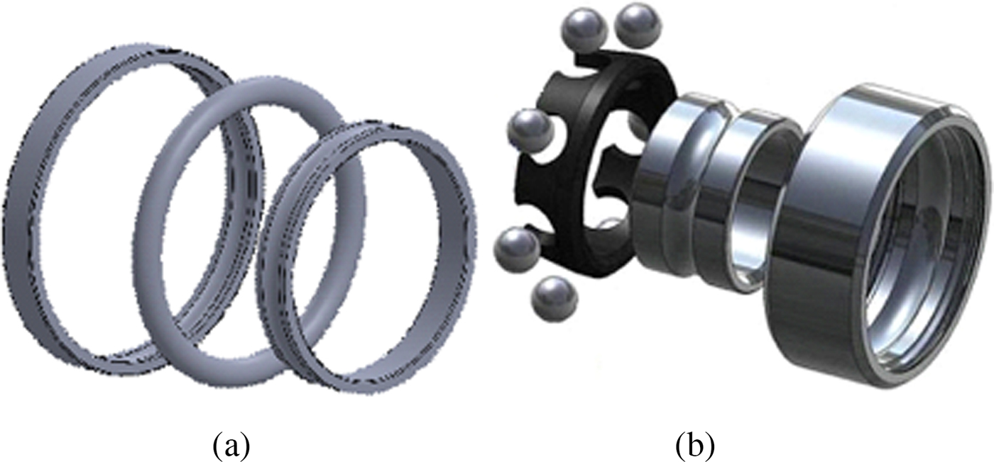
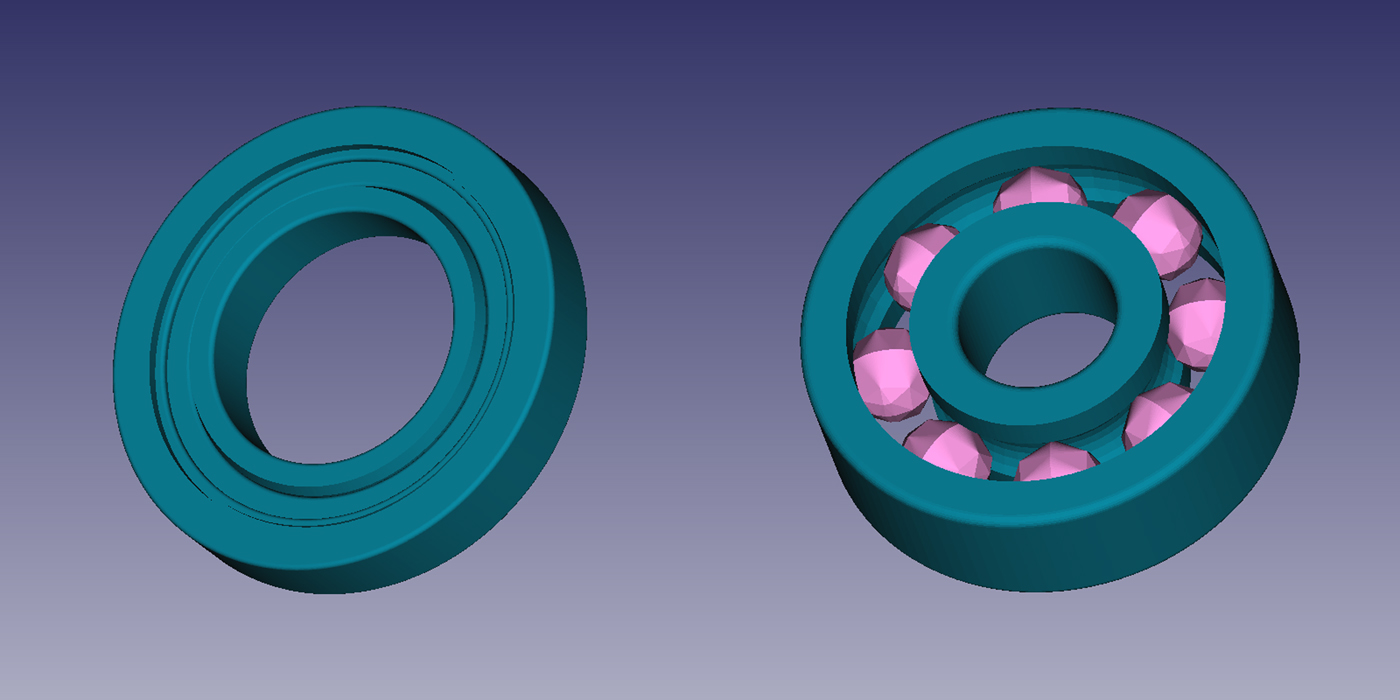
Our dataset is obtained by collecting models from different sources: the repositories mentioned above, two famous on-line free catalogs (GrabCAD (https://grabcad.com/library/software/stl) and TraceParts (http://www.traceparts.com/it/)) and projects of engineering students. Our class organization is mostly functional oriented. However, since we want to be able to classify also parts inserted in the assembly in a simplified version, we included volume primitive classes, such as sphere-like, which should be reclassified in the context-based classification revision phase. For instance, the toroidal part in Figure 2(a) and the spheres in Figure 2(b) cannot be interpreted as rolling elements of a bearing component without considering the surrounding parts. Indeed, a part with a torus shape can also be used to design a seal whose function is to ensure liquid-tightness.
Objects whose function cannot be deduced without considering usage context.
We considered the 15 classes indicated in Table 1. The class organization has been created by first allocating the objects according to their distribution in the original repositories. Additional parts have been selected from the available projects. Then, elements that could be used in the assembly with different meanings have been moved to the class that will be more easily recognized when considering its usage context. The validation of the class membership has been performed through interviews with domain experts, that is engineers and mechanical designers. Experts’ indications were particularly crucial for cataloging the parts taken from students’ projects, which are normally simplified. Thus, we designed a dataset composed of 15 categories and containing 2354 elements. Figure 3 provides pictures of the elements in the categories. The full dataset can be seen at http://partsclassifier.ge.imati.cnr.it. The categories and the number of items per category are reported in Table 1. Some categories have few elements, as there are not many variations of their shape.
Representative objects in the dataset categories.
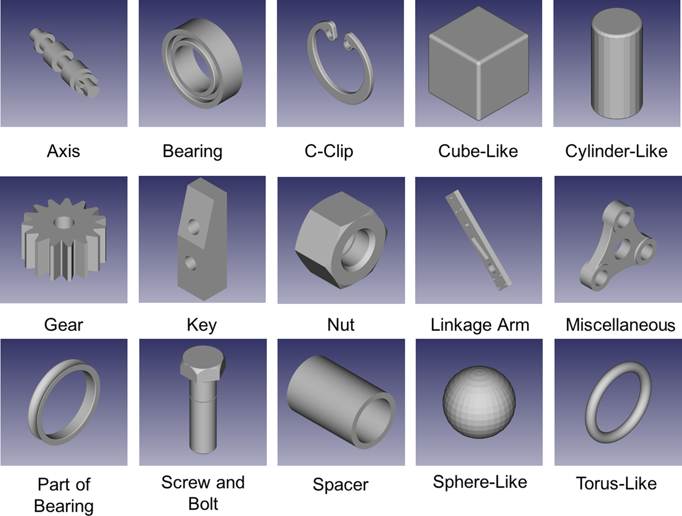
Categories in the dataset
Spacer class elements differ from those in Cylinder-like because they have at least a hole along the main axis.
Note that, we decided to introduce both the classes Bearing and Part of Bearing because a bearing can be modeled both as the assembly of the constituent parts or as a single part corresponding to the union of the composing elements. In the former case, parts can have several shapes. In a simpler abstraction a bearing can be modeled as three rings (cylinders with a central through hole); but sometimes the inner part is represented as a torus or a pattern of primitive shapes like spheres or cylinders, possibly including a cage, which fixes the position of the rolling elements whose shape is variable. Examples of different bearing representation are shown in Figure 4.
Example of bearings: in the left, a bearing modeled by three cylindrical rings; in the right, a bearing modeled by two shells and a pattern of spheres.
Some parts of bearings seem to be similar to spacers, but spacers’ length along the axis is greater than the diameter, while the parts of bearing that look like spacers have a diameter greater than the length.
Feature extraction and feature analysis
Feature extraction
Machine learning algorithms require a set of features that discriminate objects belonging to the different proposed classes by using some measurable characteristics. Since we aim to classify parts according to their shape, shape descriptors are used as features of our machine learning approach. In this paper, we do not intend to define new descriptors but to combine in a smart setting already developed geometric and statistical features. However, we have dedicated a strong effort in finding the appropriate set of features for shape classification. The literature contains tens of definitions of descriptors for shape analysis and there is no one descriptor performing in general better than others. Anyway, as shown in Jayanti et al. (Reference Jayanti, Kalyanaraman, Iyer and Ramani2006) there are descriptors that perform better for categories of shapes with specific characteristics. Thus, exploiting previous research results (Jayanti et al., Reference Jayanti, Kalyanaraman, Iyer and Ramani2006) and considering the efficiency of computation and comparison, we selected the ones more suitable for the part classes defined in Figure 3. More precisely, the objects we aim to classify are solids of revolution (e.g. axis, spacer, and screw), prismatic parts (e.g. cube and nut), and thin-walled parts (e.g. c-clip); the descriptors that best represent these classes are 3D spherical harmonics, geometric statistics (e.g. ratio among the main bounding box sizes), inner distances and shape distribution. The selected descriptors are computed with freely available tools on tessellated models, which can be produced from any CAD system and from reverse engineering processes.
To perform the classification, we project the objects to a new feature space. The feature space is formed by a collection of shape descriptors and geometric statistics, which are invariant under rigid transformations, that is their value does not change for transformation such as translations and rotations. The new feature space is of dimension 875 and it contains both integers, binary as well as real numbers.
For each object, we compute the following features:
1. 3D spherical harmonics – #544 features
2. Geometric statistics – #11 features
3. Inner distances – #256 features
4. Shape distribution – #64 features
In the following subsections, we will briefly introduce both the features included in our feature space and the light field descriptor (LFD) that we used to compare and evaluate our parts classification system.
3D spherical harmonics
3D Spherical Harmonics (3DSH) are included in the proposed feature space because of their ability to discriminate solids of revolution. In addition, this descriptor performs well also in the case of prismatic parts for values of recall after 0.3 (Jayanti et al., Reference Jayanti, Kalyanaraman, Iyer and Ramani2006).
3DSH act similar to the Fourier analysis of a signal but on spherical functions. In the study of Fourier series, complicated but periodic functions are written as the weighted sum of simple trigonometric functions. Given a spherical function f(θ, ϕ) it can be decomposed as the sum of its harmonics:
 $${\bi f}\lpar {{\bi \theta}\comma \, \phi} \rpar = \mathop \sum \limits_{{\bi l} = 0}^\infty \mathop \sum \limits_{{\bi m} = - {\bi l}}^{{\bi m} = {\bi l}} {\bi a}_{{\bi lm}}{\bi Y}_{\bi l}^{\bi m} \lpar {{\bi \theta}\comma \, \phi} \rpar $$
Where a lm are coefficients uniquely determined by:
 $$a_{lm} = \mathop \int \nolimits_0^{2\pi} \! \mathop \int \nolimits_0^\pi f\,(\theta\comma \, \phi )Y_l^{m{^\ast}} (\theta\comma \, \phi )\hbox{sin}(\theta )d\theta d\phi $$ $Y_l^m $ are the spherical harmonics, such that $\{ Y_l^m (\theta\comma \, \phi ):\vert m \vert \le l \in {\rm {\open N}}\} $ are defined on the unit sphere S 2 as:
 $$Y_l^m (\theta\comma \, \phi ) = k_{l\comma \,m}P_l^m (\cos \theta )e^{im\phi} $$
where θ ∈ [0, π], ϕ ∈ [0, 2π[, k l,mis a constant, and  $P_l^m $ is the associate Legendre polynomial, and $Y_l^{m*} $ is the complex conjugate.
In Kazhdan et al. (Reference Kazhdan, Funkhouser and Rusinkiewicz2003), the authors proposed a new rotation invariant descriptor of a spherical function for satisfying the task of shape comparison. The algorithm implements the following procedure:
decompose the function into its harmonics;
sum the harmonics within each frequency;
compute the norm of each frequency component.
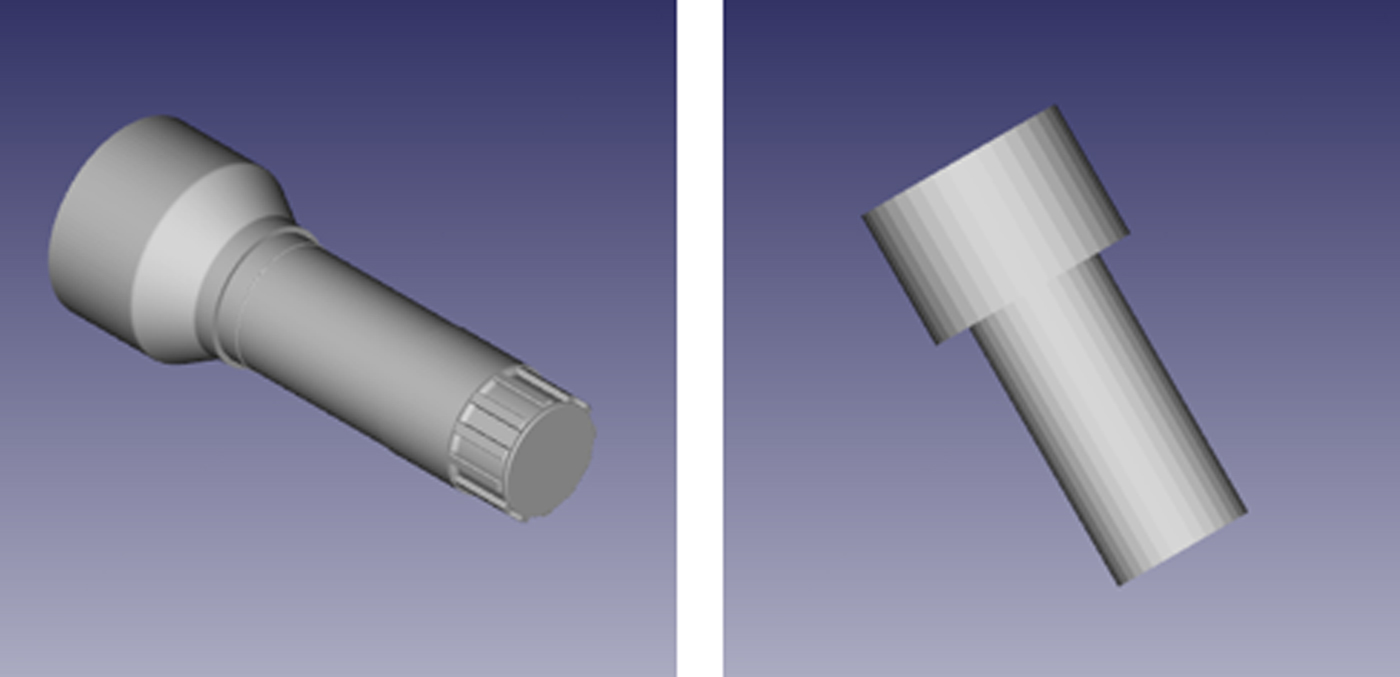
The output of this methodology is a normalized histogram, in our case of 544 bins, which reports the value of the sum of the harmonics for a given frequency. This method represents the backbone of several shape comparison algorithms (Ritchie and Kemp Reference Ritchie and Kemp1999; Rothganger et al., Reference Rothganger, Lazebnik, Schmid and Ponce2006; Mak et al., Reference Mak, Grandison and Morris2008), but in our case study it fails in the classification of very similar objects that belong to two different categories, for example, the axis and the bolt in Figure 5. In order to overcome this limitation, we add other features to our feature space.
Example of two objects (left an axis, right an abstract bolt) that are not properly distinguished by spherical harmonics but that are correctly recognized by our classifier.
Geometric statistics
Thin-walled components are characterized by higher surface area and lower volume; simple geometric statistics perform better than other more complex descriptors in their characterization. Thus, with this type of features, we intend to capture information that is able to take into consideration the sizes and the proportions among sides. In particular, the values we consider under the name of geometric statistics are:
• Minimum Bounding Box (MBB) sizes
• Proportion between length and height of MBB
• Proportion between length and width of MBB
• Proportion between height and width of MBB
• MBB diagonal length
• Surface area
• Thin shell barycentre
We start by computing the dimensions of the minimum bounding box, which is the box with the smallest measure within which all the points of the part lie in. From the bounding box, we derive other statistics, which provides indications about the global thickness of the objects.
Inner distances
The inner distances are used to build descriptor able to well characterize prismatic parts (Jayanti et al., Reference Jayanti, Kalyanaraman, Iyer and Ramani2006).
The inner distance is defined as the length of the shortest path between landmark points within the shape, and it reflects well the structure and deformation without explicit decomposition. The inner distances are stored as a histogram that gives a probability distribution of inner distances between all sample point pairs on the surface.
Shape distribution
To improve the characterization of solid of revolutions and thin-walled parts, considering the review proposed by Jayanti et al. (Reference Jayanti, Kalyanaraman, Iyer and Ramani2006), shape distribution is included in the feature space.
This descriptor is presented in Osada et al. (Reference Osada, Funkhouser, Chazelle and Dobkin2002), where the authors addressed the problem of measuring the similarity between 3D shapes by a shape function that captures global geometric properties of an object. The authors stressed the following shape functions:
• A3: measures the angle between three random points on the surface of a 3D model.
• D1: measures the distance between a fixed point (e.g., the centroid of the boundary) and one random point on the surface.
• D2: measures the distance between two random points on the surface.
• D3: measures the square root of the area of the triangle between three random points on the surface.
• D4: measures the cube root of the volume of the tetrahedron between four random points on the surface.
In Osaka et al. (2002), the authors selected the D2 and evaluated N = 10242 samples from the shape distribution and constructed a histogram by counting how many samples fall into each of the B = 1024 fixed sized bins. From the histogram, they reconstruct a piecewise linear function with V = 64 equally spaced vertices. The output of this procedure is a sequence of V integers, which forms our representation for the shape distribution. The experimental results of this approach reported in the paper and confirmed by Jayanti et al. (Reference Jayanti, Kalyanaraman, Iyer and Ramani2006) suggest us that this descriptor is a good choice for the comparison of shapes, being a good compromise considering the efficiency and the obtained results.
Light field descriptor
LFD is a self-consistent class of features that aim to capture the visual similarity of 3D objects. LFD has been introduced by Chen et al. (Reference Chen, Tian, Shen and Ouhyoung2003); it is obtained by computing the Zernike moments and the Fourier descriptors on 100 orthogonal projections of an object. The authors have developed also a 3D retrieval system based on LFD that outperforms other retrieval systems based on the spherical harmonics, the MPEG-7 Shape 3D descriptors, and the MPEG-7 Multiple View Descriptor. Therefore, to evaluate the capabilities of combining various descriptors as features, we compare our parts classification system with the one obtained by using only the LFD feature space. LFD is computed by using the tool available at http://3d.csie.ntu.edu.tw/~dynamic/3DRetrieval/. The tool takes as input the OBJ file and it produces 5 binary files. In total, an object is represented by a vector containing 6500 real values.
Exploratory analysis of the feature space
This task provides a preliminary description of the dataset in the new feature space and then helps to reduce the feature space while preserving its main characteristics. We start by computing the pair-wise standardized Euclidean distance and we store the output in a distance matrix:
 $$d(s\comma \,t) = (x_s - x_t)V^{ - 1}(x_s - x_t)^{\prime}$$
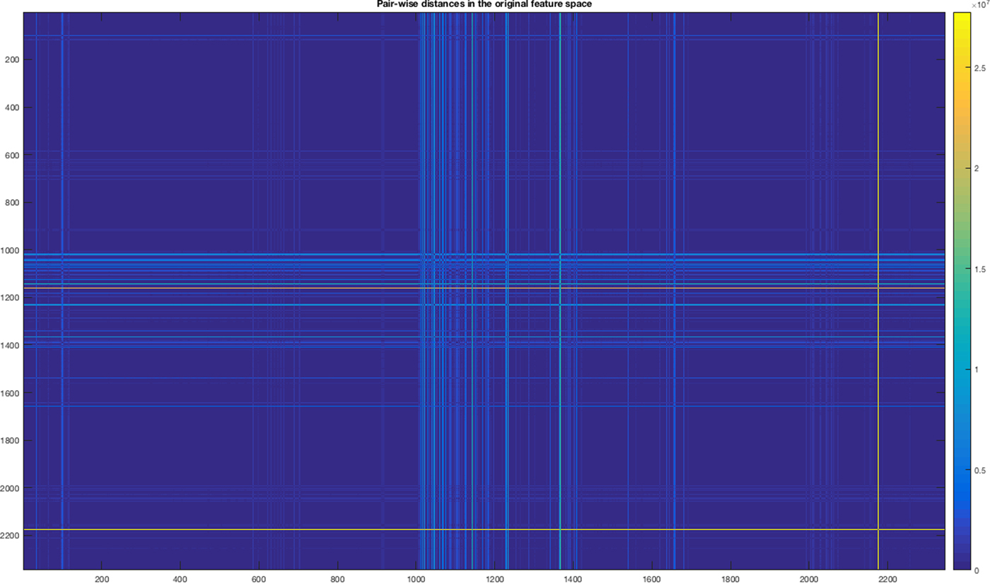
where V is the n × n diagonal matrix, whose jth diagonal element is the squared standard deviation. Among others, heat-maps are useful and informative graphical tools for mining big matrices. In our case, the distance matrix has dimension 2354 × 2354.
A heat map is a graphical representation of matrix data where the elements of the matrix are represented as colors. An example of the heat map is the mosaic map. Mosaic map is a tiled heat map for representing a two-way or higher-way table of data. The rectangular regions in a mosaic plot represent data that are hierarchically organized or that are quite similar. The analysis of the mosaic map in Figure 6 reveals a modular structure but the distances among objects tend to be quite near to zero. This indicates the necessity of enhancing the distance (separation) among objects belonging to different classes; otherwise, a metric-based clustering system could be enough and be used for classifying the mechanical parts.
Heat-map of the Standardized Euclidean distances among parts in the feature space.
Pre-processing the feature space
The previous analysis suggests that our dataset must be improved: the objects in the feature space are not strongly separated. Before to train the classification algorithms, it is necessary to check the correctness of the dataset. This step is often indicated as data scrubbing. It is the process of correcting or removing data in a dataset that are incorrect, inaccurate, incomplete, improperly formatted or duplicated. The useless or corrupted data can be detected by applying some simple statistical data validation, by handling missing data and eventually by deleting duplicate values. Missing or sparse data can lead to highly misleading results. We computed the following statistics:
• Infinite values (Inf) or number of Not A Number values (NaN)
• Number of duplicated values per feature
• Number of duplicated features
• Number of missing values
• Heteroscedasticity test (White, Reference White1998)
We did not find missing values or Inf. Normalizing each feature in the interval [0;1] is a well-known practice in Machine Learning, for this task we computed:
 $$\hbox{Norm}(x) = \lpar {x - \min (F_i)} \rpar /\lpar {\hbox{max(}F_i{\rm )} - \hbox{min(}F_i{\rm )}} \rpar $$
where x is the xth sample within the feature F i.
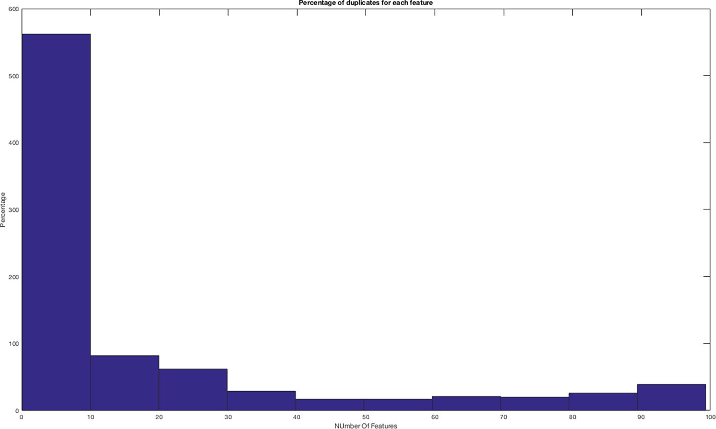
In Figure 7 we show the percentage of duplicates for each feature (spherical harmonics, geometric statistics, inner distances, and shape descriptors’ distribution), the corresponding values are reported in Table 2.
Percentage of duplicates for each feature.
Frequency of features with duplicated values
We have found that only one feature (i.e. the 57th spherical harmonics) contains the 98% of duplicates, with a value equal to zero.
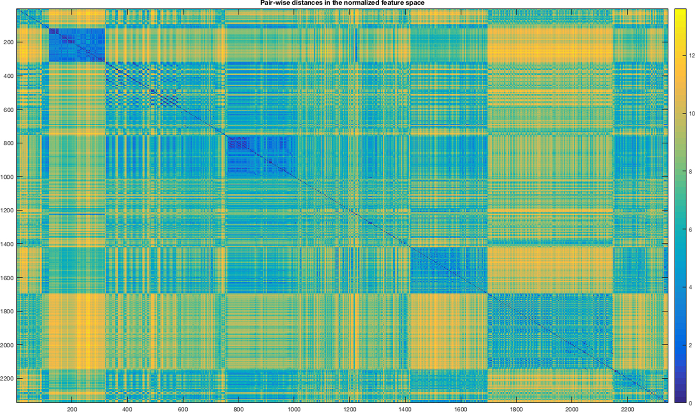
After the normalization, we evaluated the effect of the duplicates on the distances among features by iteratively removing the features with duplicates. We removed first the features with a higher number of duplicates, then at each iteration the others. We observe that the removal of the set formed by 43 features belonging to the last bin (4 spherical harmonics and 39 shape descriptors’ distribution) allows to pinpoint out a more evident modular structure of the feature space for our data set, see Figure 8. The removal of other sets degrades the modular structure. This step has improved the class separation but some classes are still overlapping and for this reason, we cannot use metric-based clustering systems for the parts classification and a non-linear interpolator is needed.
Heat map of standardized Euclidean distance matrix after data scrubbing. The modularity appears more evident.
Feature selection
In order to improve the quality and reduce the computational time and the memory usage of the classifier, we perform a reduction of the feature space. Feature selection techniques can be classified into three sets: wrapper, embedded, and filter. In the wrapper approach, the algorithm for the classification is directly involved and is used for scoring a given subset of features. The embedded methods are basically iterative algorithms that add the selection process into the learning schema of the classifier. Filter methods use statistics for analyzing intrinsic properties of data and they work regardless of the classification algorithm. Generally, the output of the feature selection is a rank or a subset selection. In the former, the importance of each individual feature is evaluated, while in the latter, the final subset of features to be selected is provided (Yu and Liu, Reference Yu and Liu2003).
We provide a mixed selection technique that puts together ranking and subset selection and that aims to preserve the modularity of our dataset that we observe in Figure 8. Our procedure works as follows:
Input: the feature space after the data scrubbing step
(1) Rank each feature
(2) Sort the rank array from the greatest to the smallest
(3) Loop over the rank array, be the current threshold θ:
(a) Select the features with the rank ≥ θ
(b) Study the similarity of the subset given by point (a)
(c) Discard θ which do not preserve the modularity
Output: the smallest set of features preserving the modularity of the input feature space.
With this schema in mind, we implemented the procedure by using two different ranking systems for point 1: F-test and mutual information (MI). After that, we discarded F-test because it was not able to pinpoint out any relevant features. This is because F-test deals only with highly linear correlated variables, while MI is able to detect any kind of dependency among variables.
F-test
This features selection approach belongs to the filter methods and it is based on the so-called F-statistic. The F-statistic is simply a ratio of two variances. Variances are a measure of dispersion, or how far the data are scattered from the mean. Larger values represent greater dispersion. The F-test score assesses if the expected values of a quantitative random variable x within a number of m given classes differ from each other (Steiger, Reference Steiger2004).
Mutual information
The MI between two random variables or random vectors measures the “amount of information”, that is the “loss of uncertainty” that one can bring to the knowledge of the other, and vice versa. MI can be used in several ways to select a subset of features (Krier et al., Reference Krier, Francois, Wertz and Verleysen2006).
The first strategy consists of measuring the MI between the ratio of two features (x 1/x 2) and the class label: the highest scores correspond to those features that are most relevant in discriminating among the classes. This method finds pairs of useful features but it is not suitable for scoring each individual feature. The second approach is more useful for building a bag of features: the feature with the highest MI with the class label is chosen first. Then, pairs of features containing the already selected one and any remaining one are built. The MI between each of these pairs and the class label are measured; the second chosen feature is the one contained in the pair with the highest MI score. The procedure is then iterated until the adequate number of features has been reached.
In this paper, we use the second approach and it selects 437 out of 832 features:
• Spherical harmonics: #243
• Geometric statistics: #6
• Inner distances: #143
• Shape Distribution: #45
The application of MI to the LFD space lets to reduce its dimensionality from ℝ6500 to ℝ3250.
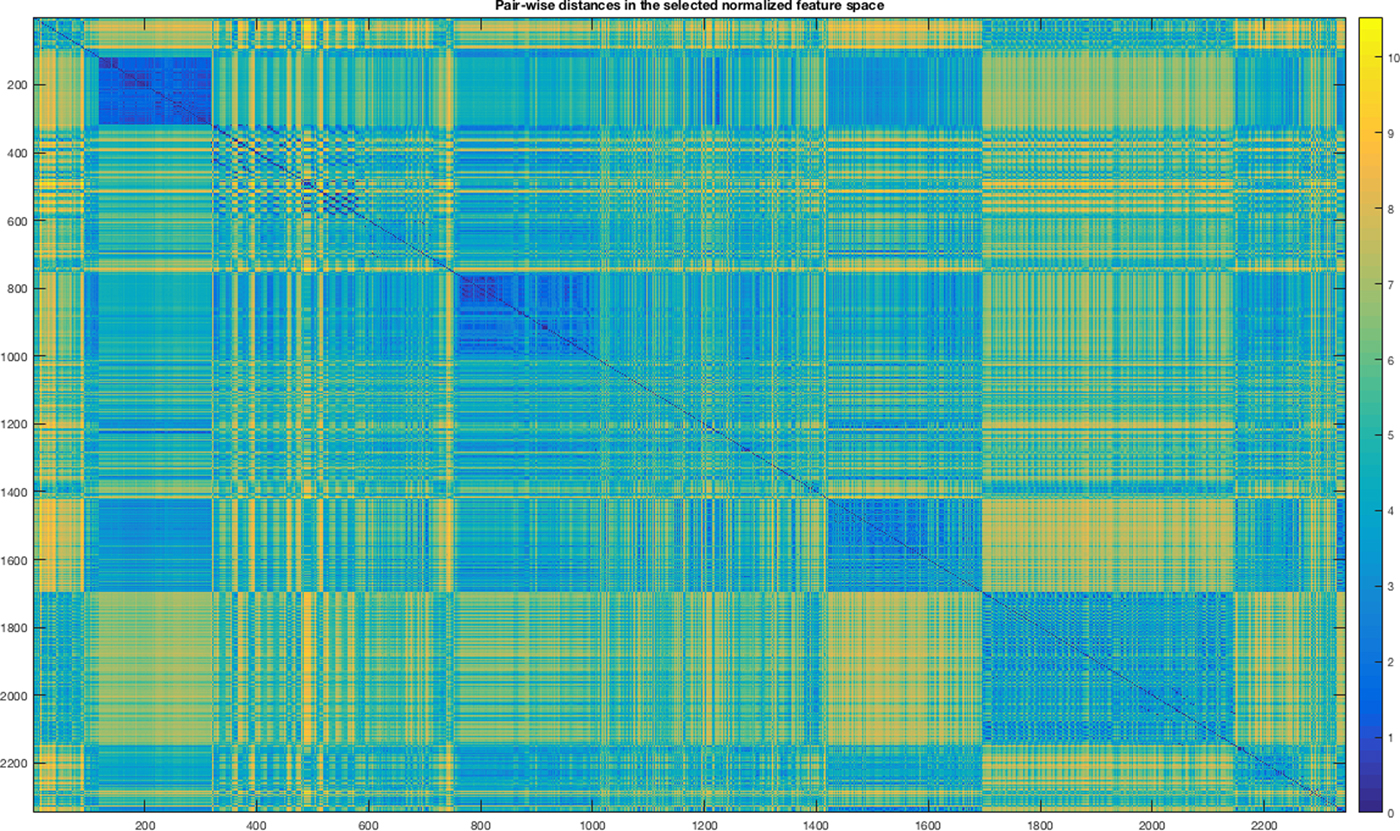
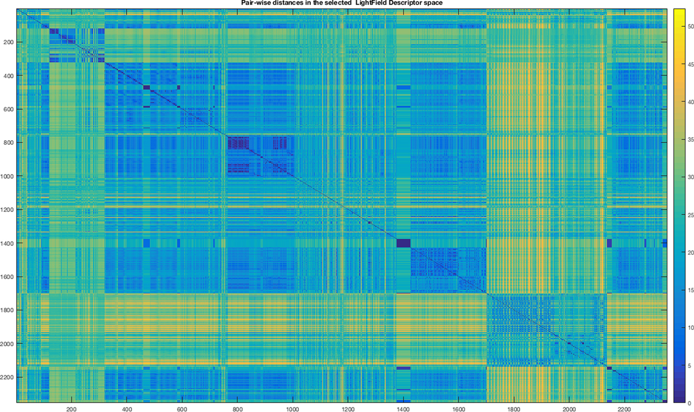
In Figures 9 and 10, we show the mosaic maps of the standardized Euclidean distances among the objects within the input dataset represented both in our feature space and by the light field descriptor after the application of the MI. In both mosaics, we notice modular structures representing groups of parts.
Heat map of standardized Euclidean distance matrix of the feature space and selected by MI.
Heat map of standardized Euclidean distance matrix of the Light Field Descriptor space and selected by MI.
Feature reduction
For the sake of completeness, we notice the reader that another approach for the reduction of the dimensions of the feature space is obtained by combining subsets of the input features. The combination can be linear or not. Principal Component Analysis (PCA), Linear Discriminant Analysis (LDA) and Independent Component Analysis (ICA), Factor Analysis and Projection Pursuit are the main techniques used for the feature reduction. For a complete review of these techniques, we suggest Fodor (Reference Fodor2002).
The application of PCA to the selected feature by MI reduces the dimension from ℝ437 to ℝ41. When PCA is applied to the LFD features selected by MI it reduces the dimension from ℝ3250 to ℝ49.
Modeling the classifier
In this work, we implement the “modelling” step by using a machine learning approach; we use a supervised artificial neural network (ANN) as a classifier, and the one-versus-rest classification schema (Hong and Cho, Reference Hong and Cho2008).
An ANN is a computational network inspired by biological neural systems, consisting of nodes (neurons) and links for connecting the nodes. For more details please refer to Ruck et al. (Reference Ruck, Rogers, Kabrisky, Oxley and Suter1990). Historically ANNs have been enrolled for dealing with dichotomous classification problems. In order to use an ANN for a multi-class problem, a one-versus-rest training schema is required. This strategy consists in fitting one classifier per class. For each classifier, the class is fit against all the other classes. Since each class is represented by one specific classifier, it is possible to gain knowledge about the class by inspecting its corresponding classifier. This schema works as follows:
Inputs:
• A learner algorithm for the binary problem
• A sample space X
• A label set Y, where the label y i is the label for the sample Xi and where i ∈ {1, …, K},
Output:
○ a list of classifiers f k for k ∈ {1, …, K}
Procedure:
• For each k in {1, …, K}
○ Construct a new label vector z where z i = 1 if y i = k and z i = 0 otherwise
○ Apply the ANN to $\{ X\; \cup z \} $ to obtain f k

The procedure selects as classifier the one that, given a new sample x, classifies the label k by maximizing the following score:
 $$\hat y = \hbox{argmax}\; f_k(x){\rm \; where}\; k\; \in \lcub {1 \ldots K} \rcub $$
We use the feedforward backpropagation algorithm as learner algorithm and the output is a collection of weights matrices, one for each class. We use logistic loss function for optimization and L-BFGS as optimization routine (Dong and Nocedal, Reference Dong and Nocedal1898). We optimize the computational time by switching on the warm-start parameter (Ma et al. Reference Ma, Theiler and Perkins2003). We implement the ANN in Python and using the SciKit-MPLclassifier (http://scikit-learn.org/stable/) class and as IDE for development the PyDEV (http://www.pydev.org) plugin for Eclipse. The experiments are executed on a MacBook Air 13″ laptop equipped with a processor 1.6 GHz Intel Core i5, Ram 8GB DDR3@1600 MHz and Hard Disk technology SSD. OSX El Capitan.
In order to find the best topology, in terms of a number of neurons in the hidden layer, we build and train several ANNs both for the feature space that we engineered and for the LFD space. Given a dataset representation that is formed by the features selected by MI or by MI + PCA, we build n-ANNs where n = 3*2*#Feature. Each ANN is characterized by a number of neurons within the interval [3; 2*#Feature]. For statistical purposes, for each given number of neurons, we build 3 same ANNs. For each configuration, we train the ANN and we test its classification capabilities by adopting a k-cross-validation approach, with k = 10. For each run, we measure the accuracy of classification for each category and the average accuracy and the standard deviation. We select as winner configuration the one that maximizes the average Area Under Curve (AUC). For the sake of clarity, we perform the following data experiment:
1. Split the dataset into two subsets: Training and Test. The Training set contains the 70% of items from the input dataset.
2. Train the classifier by changing iteratively the number of neurons and the number of hidden layers.
3. For each category, compute the receiver operating characteristic curve (ROC) and its AUC.
We recall that the ROC curve is the plot that displays the full picture of the trade-off between the sensitivity (true positive rate) and 1-specificity (false positive rate) across a series of the inherent validity of a diagnostic test. Total area under ROC curve is a single index for measuring the performance of a test. The larger the AUC, the better is the overall performance of the test to correctly classify items. Equal AUCs of two tests represent similar overall performances but this does not necessarily mean that both the curves are identical (McClish, Reference McClish1989).
In Table 3, we report the winner ANN for each configuration and the AUC obtained for each category. The ANNs with the highest performances are the ID 2 and ID 5. The ANN at ID 2 is obtained by using as input training space our features selected by using MI after the normalization. ANN at ID 5 is obtained by using as input space the LFD selected by MI. The difference in the performances can be explained by observing again Figures 9 and 10. In the latter figure, corresponding to the LFD, there are smaller modular structures colored with blue (distances close to zero) with respect to our feature space. It means that LFD is more suitable for answering the problem “classify a part by finding an exact match within the training set”. While our system is more suitable for solving the problem “classify a part by finding at least a similar shape within the training set”. Of course, the second case could return more false positives if in the training set there are several shapes similar to the given one but belong to different classes; this is not a fault of the classification system but of how the training has been engineered. Eventually, we select the configuration with ID 2. In Table 4, we report the AUC for each category considering the winner configuration.
Best ANN performance: top ANN architecture. Bottom: corresponding AUCs
AUC for each category for the ANN with ID 2

For the sake of generalization, beside our numerical results, which are limited to the dataset we have analyzed so far, we believe that our classifier outperforms LFD-based classifier because LFD is a powerful tool for performing a global description of shapes, while our feature space combines both global descriptors (spherical harmonics) with local shape descriptors (e.g. inner distances). Moreover, LFD is not a natural vector space (need to search over rotations for the comparison of different 3D objects), so it is not possible to apply traditional methods to accelerate nearest neighbor search, while our feature space can be queried with Euclidean like metrics.
Another relevant aspect regarding data storage is that the LFD space is formed by 6500 values, while our original feature space is composed only by 875 values; both are formed by float numbers. In this consideration, we are discarding the dimension of the feature space after feature reduction because it depends on the characteristics of the dataset under analysis.
Result analysis
The concept of deployment in predictive data mining refers to the application of a model for prediction of new data. To validate the classifier described in the section ‘Modelling the classifier’, we applied it on a dataset containing 606 unknown 3D objects. Please see Table 5 for details on the dataset composition. Because we know the category of the objects, we can evaluate the quality of the classification by computing several similarity indices; we chose the following ones, which, as far as we know, are the most used in the literature Tustiton and Gee (Reference Tustiton and Gee2009):
• Jaccard index (or similarity coefficient of Jaccard)
• Dice coefficient
Unknown 3D objects set classified by the ANN

The Jaccard index measures the similarity between two sets by dividing the cardinality of intersection with the cardinality of their union:
 $$J(C_i\comma \,C_j) = \displaystyle{{\vert {C_i\mathop \cap \nolimits^ C_j} \vert } \over {\vert {C_i\mathop \cup \nolimits^ C_j} \vert }} $$
Dice coefficient is nowadays widely used for asserting the quality of classification. This coefficient is not very different from the Jaccard index. However, since it does not satisfy the triangle inequality, it can be considered a semi-metric version of the Jaccard index; it is defined as follows:
 $$D(C_i\comma \,C_j) = \displaystyle{{2 \times J(C_i\comma \,C_j)} \over {1 + J(C_i\comma \,C_j)}}$$
In this experiment, we obtain the coefficients listed in Table 6:
Quality of classification of 606 unseen parts

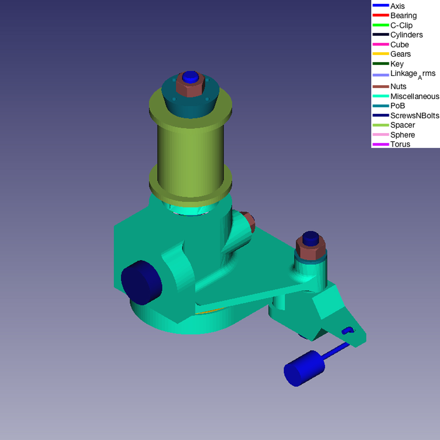
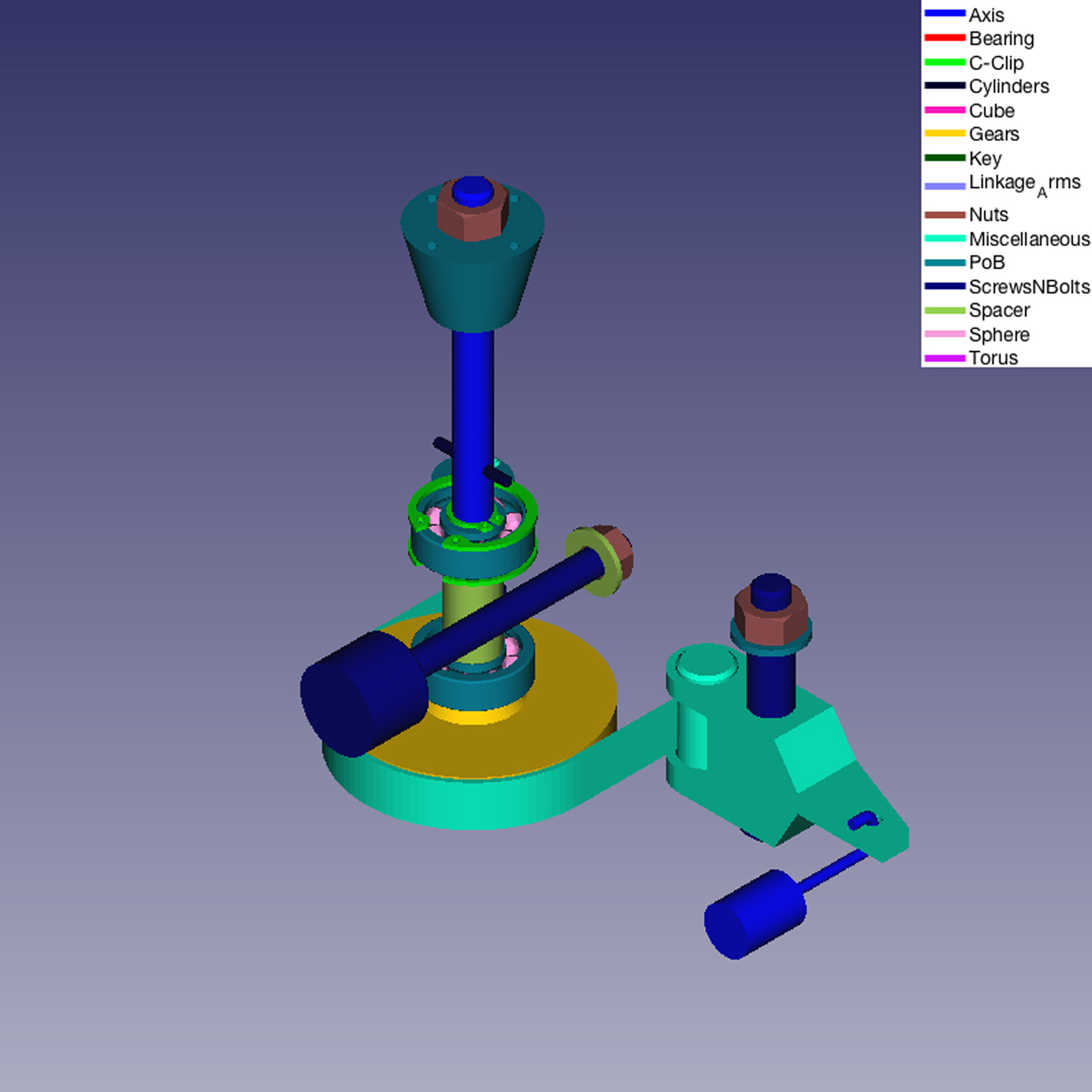
We also applied our classifier system for the classification of parts belonging to real mechanical assembly models. Figures 11–14 show some examples.
Example of classification of a real Mechanical Assembly Model.
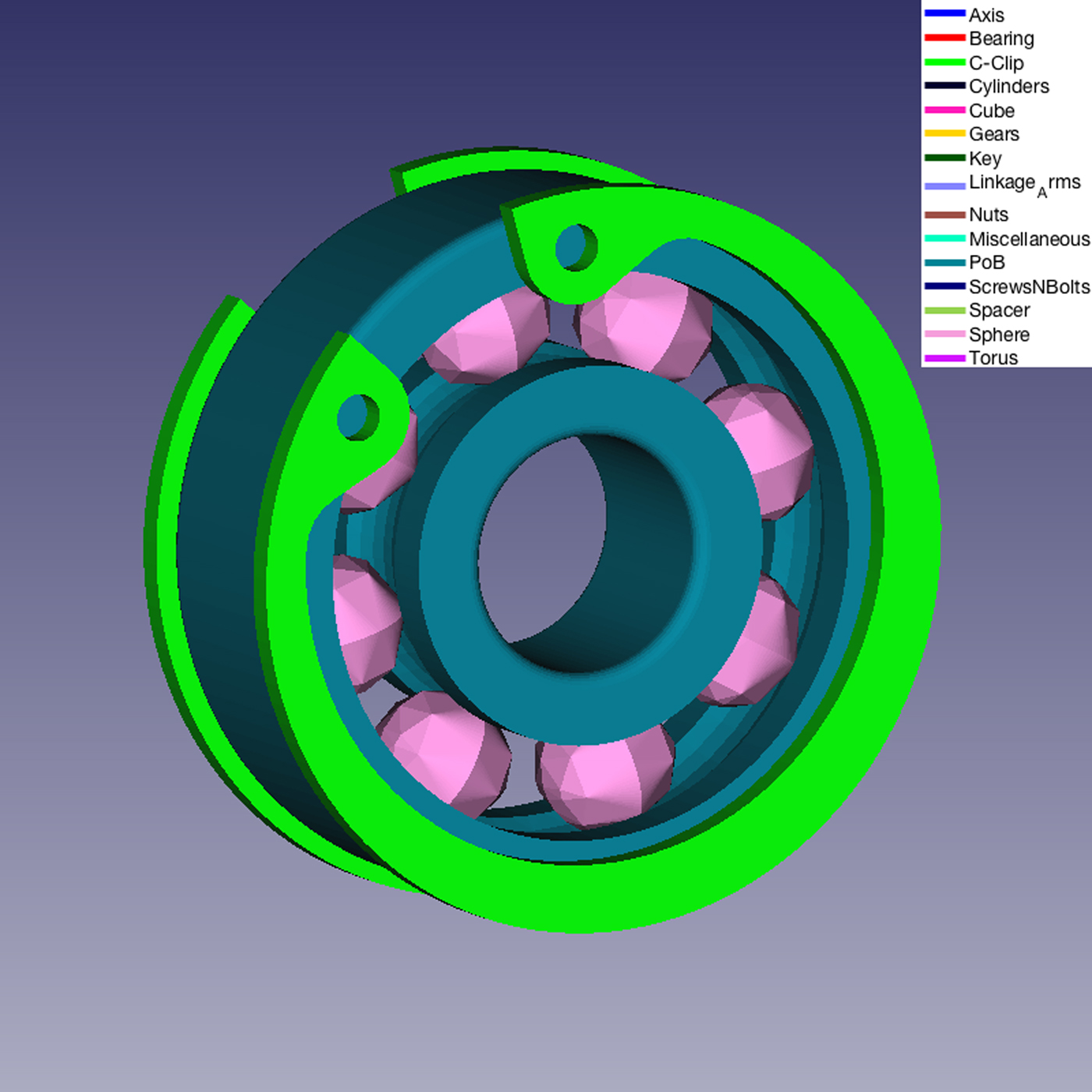
The same model in Figure 11 with the removal of the carter.
A detail of the Mechanical Assembly Model in Figure 12. A bearing (made of two Part of Bearing and a series of Sphere-like parts) and C-Clips.
A real Mechanical Assembly model. On the right two objects that are properly classified in terms of shapes but not are properly classified from the functional point of view.
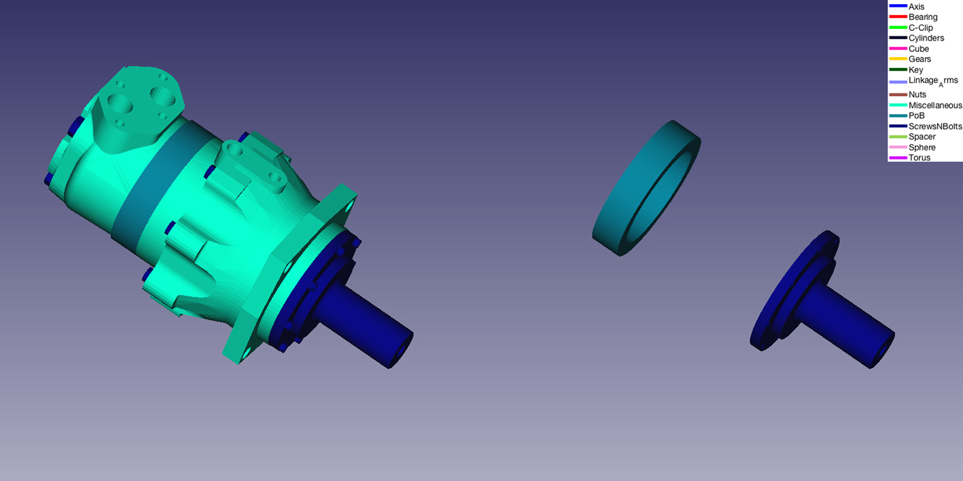
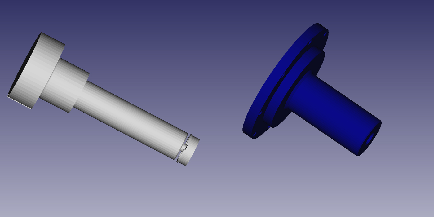
Examples of wrong classifications are shown in the left of Figure 14. The ring is classified as Part of Bearing because its diameter is greater than its length, which is one of the rules we used to create the Part of Bearing category set. While the second element is classified as a bolt. The reason is that in the category Screws and Bolt of our dataset there are some abstract bolts similar to the object colored in blue (Fig. 15). In both cases, the context-based revision of the shape classification we proposed in Lupinetti et al. (Reference Lupinetti, Giannini, Monti and Philippe2017) is able to correct the misclassification by considering the contacts with the other parts in the assembly.
Left a bolt; right the object of Figure 14 incorrectly classified as a bolt.
Summary and conclusions
In this paper, we present in a pedagogical fashion the application of a step-by-step data analysis process for the definition of an automated system for classification of mechanical components using a machine learning approach. We report how we implemented all the steps of such a process: from the data acquisition to the deployment of the classifier. We start building a dataset of 2354 3D parts subdivided into 15 sub-categories. Then we perform the feature extraction giving rise to a domain with dimension ℝ875. On the feature space, we perform feature scrubbing and feature selection, thus reducing the space to ℝ437. We illustrate how to set-up and tune a supervised classifier with an ad-hoc classification schema, the so-called one-versus-rest. This schema returns a collection of classifiers each of which optimized for the classification of a specific sub-category. The classifier is a multi-layer ANN with a hidden layer and 230 neurons. We state the quality of the classifier in terms of average AUC = 95.72%. Eventually, we deployed the model to 606 unknown objects. The well-trained classifier achieves relatively high classification accuracy on new 3D models: Jaccard index = 92,43% and Dice coefficient = 96,06%. Experimental results are promising. The average time spent for the classification of the 606 parts is sufficiently short: 2,3 s. We implement our procedure also by using a different feature space, the LFD. For the dataset under examination, our system outperforms the ones based on LFD. Moreover, LFD needs a huge amount of memory, because each 3D object is represented by 6500 real values, while our feature space has dimension 875.
The classification of parts in real mechanical assembly models highlighted that, even if the shapes are properly classified, the correct functional interpretation can be achieved only considering their context of use. For this reason, the presented classifier constitutes the first step of the module described in Lupinetti et al. (Reference Lupinetti, Giannini, Monti and Philippe2017), which classifies functional component in assembly models reasoning both on the shape of its elements and on their organization within the model. We hope the reader can use this paper as a signpost in his or her personal quest to perform a convenient data analysis process.
To evaluate the possibility of improving the classification rate, we are considering various possible extensions of the presented work. The first refers to the inclusion in the feature vector of additional shape information directly available in CAD models, such as, for any specific surface type, the number of faces and the surface percentage relative to the overall area of the object. Another potential improvement could be obtained by using Constrained Machine Learning (CML) techniques as classification engines. CML extends classical machine learning techniques by adding declarative constraints, for example, mandatory characteristics or how two mechanical elements can be in touch. The constraints can be used as a way to incorporate domain and engineers’ knowledge that must be always satisfied while the classification task (Teso et al., Reference Teso, Sebastiani and Passerini2017).
Acknowledgements
The authors thank Anita Parodi for the support provided in the model collection and the contacted experts, in particular, Prof. Jean Philippe Pernot, for the support in the engineering domain.
Matteo Rucco is a data scientist whose main research focuses on combining machine learning and topological data analysis for extracting insights from the big dataset. Matteo is currently a researcher at A.L.E.S. - United Technologies Research Center Italy. Previously, he was a post-doc at Italian National Council of Research, Institute of Applied Mathematics and Information Technology and, a PhD student at the School of Advanced Studies at University of Camerino and supervised by Prof. E. Merelli. Matteo obtained the M.Sc. in Computer Science from the University of Camerino and the B.Sc. in Physics from the University of Salento, Italy.
Franca Giannini is a research director at IMATI - CNR in Genova, Italy. She graduated in applied mathematics in 1986. She has participated and been responsible for IMATI in several national and international projects. She acts as a tutor in Master and PhD thesis and as program committee member and chair for various international conferences. She is a co-author of two patented software for automatic feature recognition and representation. The results of her research activity have been published in more than 110 reviewed papers. Her current research interests include geometric and semantic modeling, 3D objects analysis and Virtual Reality applications.
Katia Lupinetti is a research fellow at the National Council of Research in the Institute of Applied Mathematics and Information Technology in Genoa since March 2014. She has a M.Sc. in Mathematics from the University of Genoa and a Ph.D. in mechanical engineering from both the École National Supérieure d'Arts et Métiers and the University of Genoa. Her main research goal is the definition of methods as well as the development of tools, which ease the design of mechanical products by combining aspects of design theory, 3D model representation, data retrieval, and recent tools for the visualization in virtual reality.
Marina Monti is involved in academic research since 1999 when she joined CNR-IMATI, after 14 years of experience in R&D departments of CAD companies, where she managed several research and application projects. Her main research focuses on representation and analysis of 3D models and knowledge management technologies, focusing on methods adaptable to different application areas through the exploitation of the specific context knowledge. She acted as reviewer of several international journals and conferences and an international expert for the European Commission. She has published extensively in high profile journals and conferences and is a co-author of more than 70 papers.


