


Introduction
The ice core recovered from the 5G-1 hole at Russia's Vostok Station in Antarctica in the late 1990s provided a wealth of information about past climate and environmental changes through the last four glacial–interglacial cycles (Petit and others, Reference Petit1999). The 420-ka long climatic record was obtained from the first 3310 m of the Vostok core characterized by an undisturbed sequence of meteoric ice layers (Fig. 1). Below 3310 m (All depths reported in this paper are the ice core logging depths obtained from the core length measurements.) and down to 3539 m, the upper boundary of the 230 m thickness of accreted ice (3539–3769 m), the meteoric ice has experienced severe deformation, which made itself evident in the deformed volcanic ash layers observed at a depth of 3311 m (Petit and others, Reference Petit1999) and in the overturned ice fold discovered in the depth interval between 3318 and 3342 m (Raynaud and others, Reference Raynaud2005). Due to ice mixing and diffusive smoothing of the climatic signals (see deuterium profile in Fig. 1), extracting useful paleoclimatic information from this section of the core, which according to the recent study dates back to 1.2 Ma BP (Lipenkov and others, Reference Lipenkov2019), is a challenge. Nevertheless it has been argued (Lipenkov and Raynaud, Reference Lipenkov and Raynaud2015) that implementing a project focused on the old Vostok meteoric ice (referred to as the Vostok Oldest Ice Challenge or VOICE) could shed light on how and to what extent the old Antarctic ice may help in deciphering the enigma of the Mid-Pleistocene climatic transition, the main scientific goal of the Oldest Ice Core project proposed by the planning group International Partnership in Ice Core Sciences (http://pastglobalchanges.org/science/end-aff/ipics/intro).

Fig. 1. Schematic representation of the vertical structure of the Antarctic ice sheet in the vicinity of Vostok Station and configuration of multibranch borehole 5G. Lost drills are shown by crosses. The lower sections of holes 5G-1, 5G-2 and 5G-3 are filled with frozen Lake Vostok water. The deuterium profile (red curve, axis is not shown) is composed from available published data (Petit and others, Reference Petit1999; Souchez and others, Reference Souchez, Jean-Baptiste, Petit, Lipenkov and Jouzel2002; Ekaykin and others, Reference Ekaykin, Kozachek, Lipenkov, Preobrazhenskaya and Shibaev2013).
The first core representing the whole thickness of the old disturbed ice was drilled as part of a long-term collaboration between Russia, the United States and France, from hole 5G-1 (Fig. 1). The ice core had been distributed equally among the three countries and intensively used for different analyses. In 2013, in the course of re-drilling hole 5G-1, which had become filled with frozen sub-ice water after the first unsealing of Lake Vostok, the drill deviated from the parent hole and started the new 5G-3 branch hole at a depth of 3458 m, thus yielding a replicate core of old ice from the depth interval 3458–3539 m (Fig. 1).
Following up the VOICE initiative, in the 2018/19 austral season, a new deviation from the 5G-1 deep hole at Vostok was made at depths from 3270 to 3291 m, with the aim of obtaining a new replicate core of old ice suitable for high-resolution measurements of various ice properties using the continuous flow analysis technique. The replicate coring was to address the following specific tasks:
1. Obtaining a full-diameter replicate core containing volcanic ash layers previously found in the 5G-1 core at a depth of 3311 m. The layers mark the beginning of the disturbed ice and can be used for synchronizing the depth of new 5G-5 ice core with that of the existing 5G-1 core.
2. Ensuring a minimal distance (⩽ 500 mm) between the new and old holes at the depth where the ash layers occur in order to increase the likelihood of their presence in the new core. Note that these layers, which represent the oldest tephra-bearing ice layers so far detected in deep Antarctic cores, have not been found in the EPICA DC ice core (Narcisi and others, Reference Narcisi, Petit and Delmonte2010).
Apart from obtaining a continuous core of the old disturbed ice, the drilling of the 5G-5 hole is also targeted at re-sampling (for the fourth time) the upper section of the Lake Vostok accretion ice (Fig. 1). Of particular interest here is the layer at 3607 m depth containing mineral inclusions of the lake-bottom sediments, a study of which has already provided much information about the geological setting, limnological characteristics (Leitchenkov and others, Reference Leitchenkov, Antonov, Luneov and Lipenkov2016), and microbial content (Bulat and others, Reference Bulat2004) of Lake Vostok.
Based on the case of the 5G-5 drilling, we describe here the method and operating procedures for replicate coring at a targeted depth in an existing slant hole using a standard cable-suspended electromechanical drill. This method for multibranch hole drilling was designed at the St. Petersburg Mining University. It was tested at Vostok for the first time in January 2007, when sidetracking was initiated to bypass the drill lost in 5G-1 hole and branch-hole 5G-2 was extended toward the base of the ice sheet (Fig. 1).
Theory
When boreholes are drilled in ice, the cable-suspended drill tends to deviate from the vertical if the cutter head is in constant contact with the hole bottom (Vasilev and others, Reference Vasilev, Podoliyk and Dmitriev2014, Reference Vasilev, Podoliyk, Dmitriev, Bolshunov and Vasilev2019). For this reason, almost every borehole drilled in ice sheets has an inclination exceeding 1° (Hansen and Kelty, Reference Hansen and Kelty1994; Jonsen and others, Reference Johnsen, Gundestrup, Yansen, Schwader and Rufli1994; Augustin and others, Reference Augustin, Panichi and Frascati2007).
Figure 2 shows a diagram of forces acting on the drill inside a slant hole. If the hole inclination exceeds 1.8°, the apex of the 10 m long KEMS 132 drill used here for the deviation rests on the downhill side of the hole, even when the drill is pulled out (Vasilev and others, Reference Vasilev, Podoliyk and Dmitriev2014).
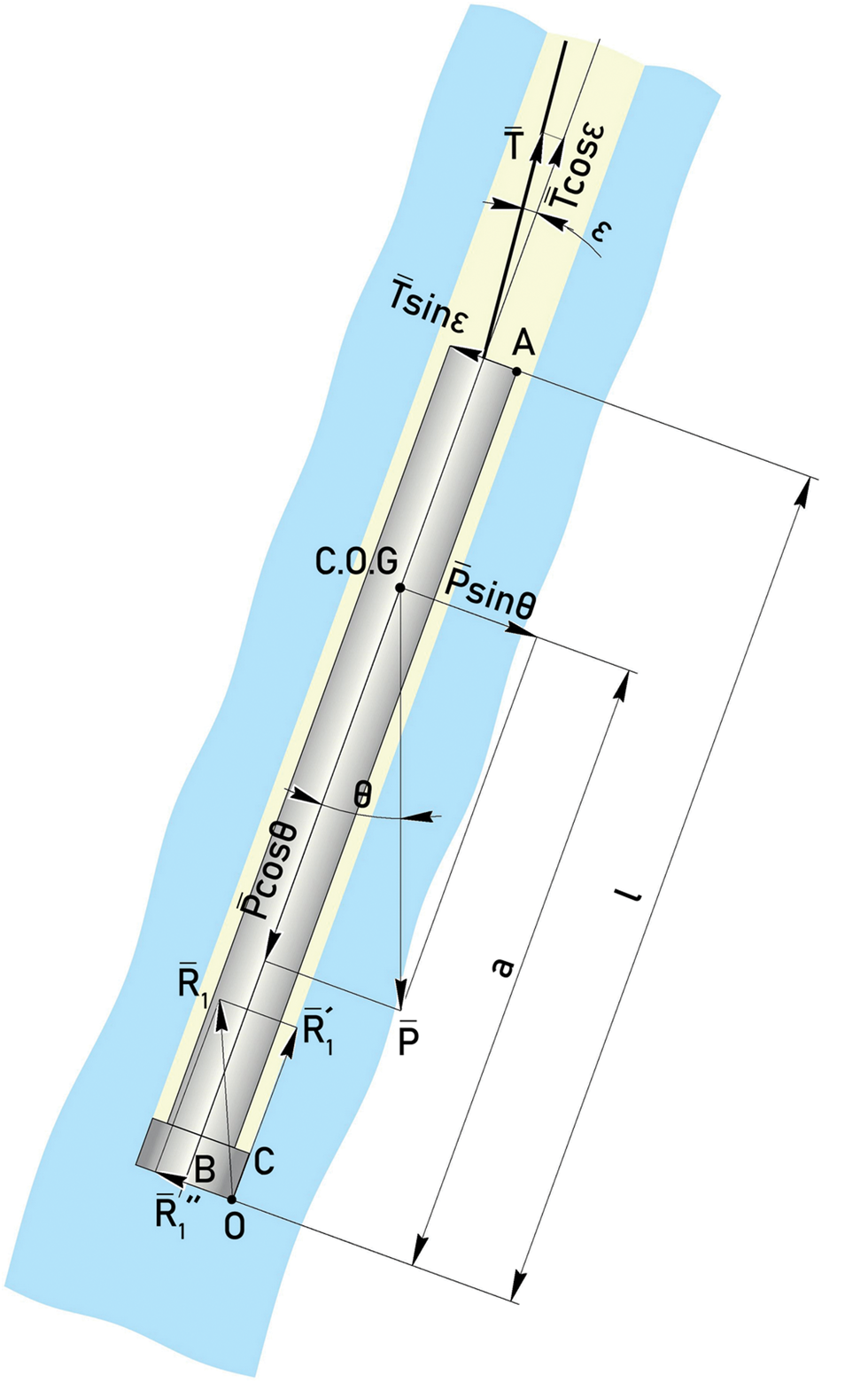
Fig. 2. Diagram of forces acting on the drill inside a slant hole: Р – weight of the drill applied to the center of gravity (C.O.G); Т – tension of the carrying cable; l – drill length; θ – borehole inclination angle; ɛ – angle between the borehole axis and the cable; ${\rm \;}\overline {R_1^{\prime\prime}}$ – borehole bottom response; $\overline {R_1^{\prime}}$
 – borehole wall response; $\overline {R_1}$
 – total overall response; а – distance from the bottom of the cutter head to the center of gravity; А, В and С – characteristic points of the drill used in calculations; О – center of drill rotation.
As the result, the drill axis is not parallel to the hole axis. When drilling, the drill is subjected to complex forces that include the weight of the drill P, the tension force of the carrying cable T and the borehole bottom response $\overline {R_1}$ . The cutters of the drill head act on the wall of a slant hole with a force equal and opposite to the normal response of the hole bottom $\overline {R_1^{\prime\prime}} .$
Ice drilling with an electromechanical drill is routinely done using cutters that are not able to cut the wall of the hole because of the cylindrical shape of the cutter's side surface. If cutting the wall is made possible, then the drill would tend to deviate to the vertical position. This appears to be the only specific feature of the drill used for sidetracking. This minor modification in the conventional cutter head design fundamentally changes the way the drill behaves inside the borehole.
A milling cutter head used for deviation has four cutters with side cutting edges to allow milling of the borehole wall (Fig. 3b). Specially designed limiters are used to control the penetration of the cutters into the wall, to lower the dynamic stresses and to stabilize the cutting state when milling a ledge in the parent hole. Figure 3a shows keyseat creation in a slanted borehole when sidetracking is initiated with a milling head.
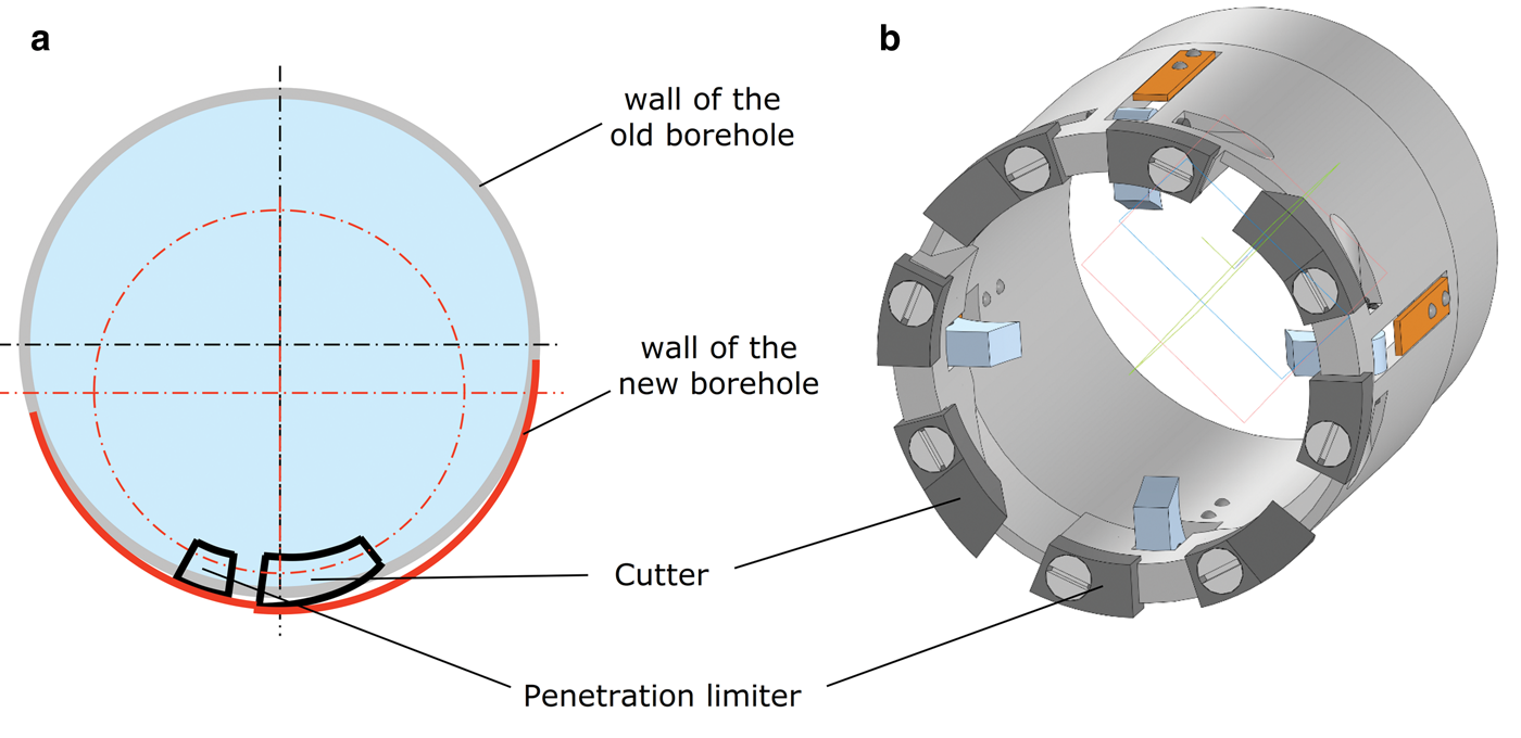
Fig. 3. (а) Scheme of sidetracking and (b) milling head.
The entire deviation process can be divided into three stages (Fig. 4):
1. sidetracking until a crescent ice core is obtained;
2. drilling with crescent ice coring until a full diameter core is obtained;
3. drilling with full diameter coring until the whole drilling assembly including the drill's antitorque section enters the branch hole.
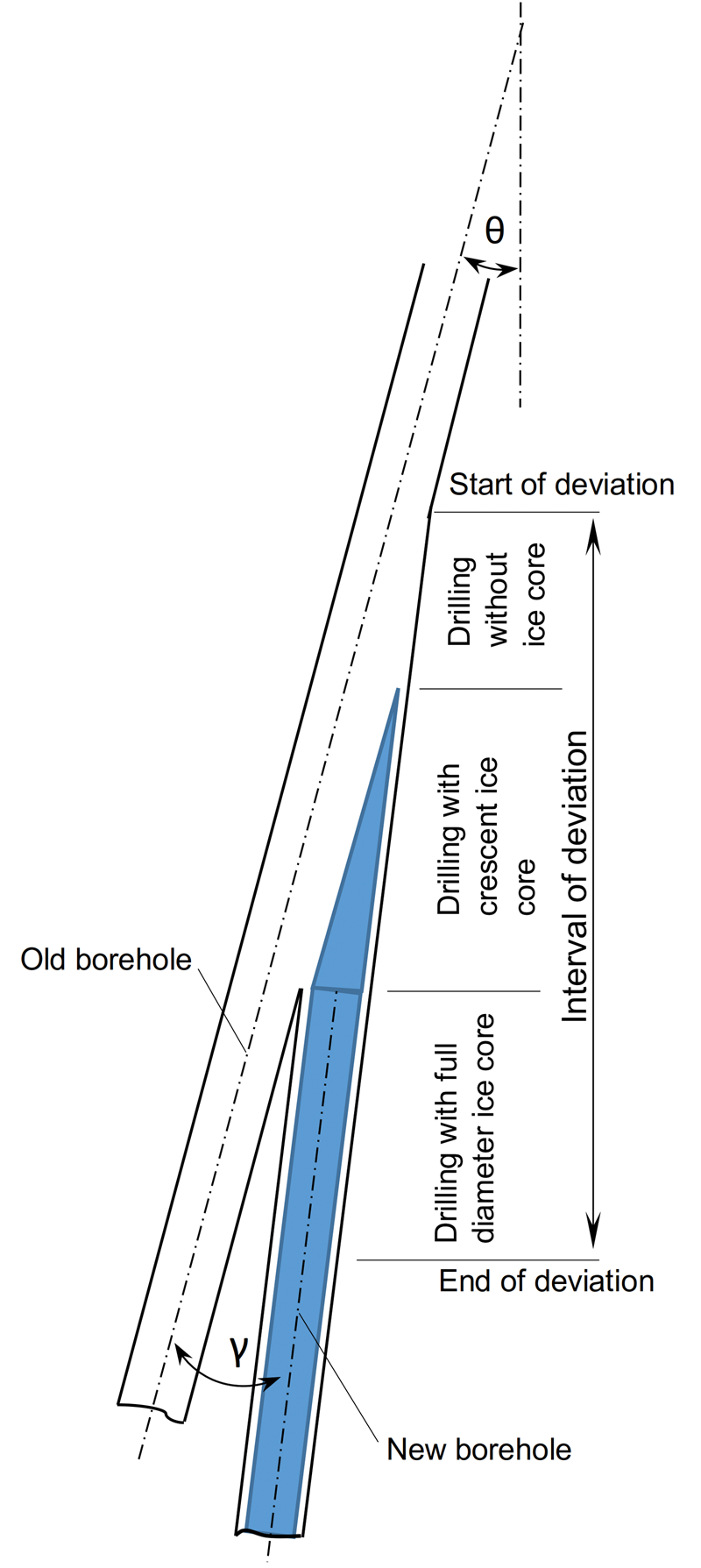
Fig. 4. Key stages of the branch-hole sidetracking.
During the initial stage оf deviation, a crescent ice core is produced which makes the use of the core catchers impractical. In routine ice coring, the core catchers slide along the smooth core surface without affecting its quality. When the crescent ice core is formed, at every turn of the drill, the core catchers get into a hollow formed by the wall of the parent hole, thus losing contact with the core surface. Having encountered the core surface on the other side of the hollow, the core catcher strikes the ice core, leaving deep annular grooves on its surface, or even destroying it. Apart from destroying the core, this results in sharp torque fluctuations at the milling head, which can cause slipping of the drill's antitorque in the hole. In order to recover an intact crescent ice core, the drilling run is made using the milling head without the core catchers, while the next run is used only to take the core with the core catchers set back in the milling head.
In-process inspection of the deviation angle is done by measuring the cross-section of the recovered crescent ice core at the top and bottom of the core.
A depth at which the sidetracking should be started was calculated taking into account (a) the request to obtain a full diameter core at a depth of 3311 m at a distance not exceeding 500 mm from the parent hole 5G-1, and (b) the minimum possible angle of the borehole curvature for a given length of the drill (10 m) (Vasilev and others, Reference Vasilev, Podoliyk and Dmitriev2014, Reference Vasilev, Podoliyk, Dmitriev, Bolshunov and Vasilev2019). The calculations showed that in order to meet the above conditions, sidetracking had to be initiated at a depth of around 3270 m, i.e. ~40 m above the 3311 m depth where the ash layers occur.
Implementation
Before starting sidetracking, the inclination and diameter of hole 5G-1 were measured in the depth interval planned for deviation, from 3260 to 3300 m. These measurements showed that within this interval the borehole inclination angle varies from 5.4° to 5.7° and its diameter changes from 138.2 to 139.5 mm, conditions suitable for making the deviation.
Sidetracking and drilling without crescent ice core recovery
In total, four drilling runs were made at this stage with a total drilling progress of 13 m. A sidetracking operation was initiated on 9 January 2019 from a depth of 3267 m. The diameter of the milling cutter head used for this operation (Fig. 5) was 137.6 mm.
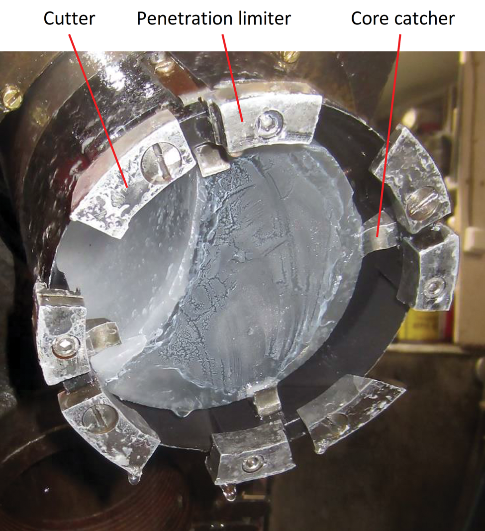
Fig. 5. Milling head for sidetracking. The four core catchers are used to break off and hold the crescent ice core inside the core barrel.
During the first run neither the penetration limiters nor the core catchers were attached to the milling head. At the very beginning of the operation the priority was to form a ledge in the parent hole (the onset of the new branch-hole), the formation of which could be checked by a weight-on-bit sensor of the drill.
Once the drill motor was started at a depth of 3267 m, the readings clearly indicated increased power consumption by the motor, which marked the beginning of the borehole wall milling process. Power consumption increased linearly as the drill was moving down, which meant that the cutter head was penetrating deeper into the borehole wall. The side force on the milling head was calculated to be about 70 N, for a borehole inclination angle of 5.5°, drill length of 10 m and drill mass of 430 kg. Drilling continued to a depth of 3277.3 m, when readings indicated that the chip chamber had been filled.
Also at the end of the first run, some surges in power consumption were observed that indicated excessive penetration of the cutting blades, which could cause slipping of the drill's antitorque in the hole. Once the motor was stopped, a successful attempt was made to land the drill onto the ledge that had already been created at a depth of 3277 m. The chips recovered in the first run were large ice grains up to 3 mm in size (Fig. 6a).

Fig. 6. (a) Run 1: chips in the chip chamber after milling a shallow ledge in the 5G-1 hole at a depth of 3277 m. (b) Run 4: fragments of crescent ice core, recovered from 3280 m. (c) Run 6: intact crescent ice core, 3285 m: d – thickness of the core cross-section. (d) Run 16: full diameter core, 3291 m: 1 – surface of the 5G-5 ice core; 2 – wall of the 5G-1 hole.
Penetration limiters (OD = 137.0 mm) and core catchers were mounted onto the milling head before the second run. The core catchers were used to destroy the crescent ice core of small thickness. The drill design allowed the collection of small core fragments measuring up to 30 mm in the chip chamber. The use of penetration limiters made the drilling process more stable, without jerks.
Upon completion of the second and third runs, we discovered 10–17 mm thick fragments of the crescent ice core among the drill cuttings. Drilling was continued until the full filling of the chip chamber. Once the fourth run was completed at a depth of 3280 m, a plug made of chips and crescent ice core fragments with a thickness of up to 30 mm (Fig. 6b) was formed in front of the filters, which indicated the need to move to the second stage of deviation.
Drilling with crescent ice core recovery
The second stage of deviation included 12 runs with a total drilling progress of 12 m (25 m from the sidetracking point). At this stage, the drilling process involved alternation of two types of runs: a coring run without core catchers in the milling head was followed by a run with the milling head equipped with four core catchers (Fig. 5). The second type of run had the sole purpose of breaking off and recovering the core. Run No.6 (Fig. 6c) produced a core with length Hcore = 1.8 m from a depth of 3284.8 m. The thickness of the cross-section of the core was dtop = 32 mm at the top of the core, and dbot = 49 mm at its bottom. These measurements were used to calculate angle θ between holes 5G-1 and 5G-5 in this depth interval of deviation:

Since the angle was found to be fit for purpose, during the following runs, the milling head configuration remained unchanged, and alternation of the ice coring and core recovering runs continued until a full diameter core (107 mm) was obtained at a depth of 3291 m, i.e. 24 m below the sidetracking point.
Full diameter coring
A total of seven runs were performed during the third stage. The total drilling progress was 10 m (35 m from the sidetracking point). Because at this stage of the deviation the drill's antitorque is still in the enlarged section of the borehole, drilling is performed with a minimum feed rate using a milling cutter head assembled with core catchers.
This milling head was used down to a depth of 3302 m when the antitorque system entered the new branch hole, thus signifying completion of the sidetracking operation for the 5G-5 hole. Further drilling was done with the conventional coring head assembled with cutters without the side cutting edges. Thus, all the sidetracking operations were performed within a 35 m long section of the borehole. Average drilling progress per run during the subsequent borehole drilling with a conventional coring head was 1.9 m.
By the end of the 2018/19 austral season, hole 5G-5 reached stratigraphic horizons at which the deformed ash layers and the overturned fold were observed in the 5G-1 ice core. Preliminarily, the depth of the new ice core was estimated using an empirical relationship between the core length and the drilling depth (i.e. cable length) established for hole 5G-1. According to this relationship, the ash layers (Fig. 7) and the upper boundary of the overturned fold, the latter being identified due to a sharp decrease in the grain size and deuterium content of ice marking an inverted transition between MIS 11 and MIS 12 in the Vostok core (Raynaud and others, Reference Raynaud2005), were found in the 5G-5 core at depths 3314.8–3315.0 m and 3322.4 m, respectively. Since the same marker beds were observed in the 5G-1 core at depths 3310.7–3310.8 m and 3318.3 m, we applied the −4.1 m correction to the preliminary 5G-5 log data to anchor the 5G-5 ice core on the 5G-1 ice core logging depth taken as reference (Note that all depths reported in this paper refer to this reference depth scale).
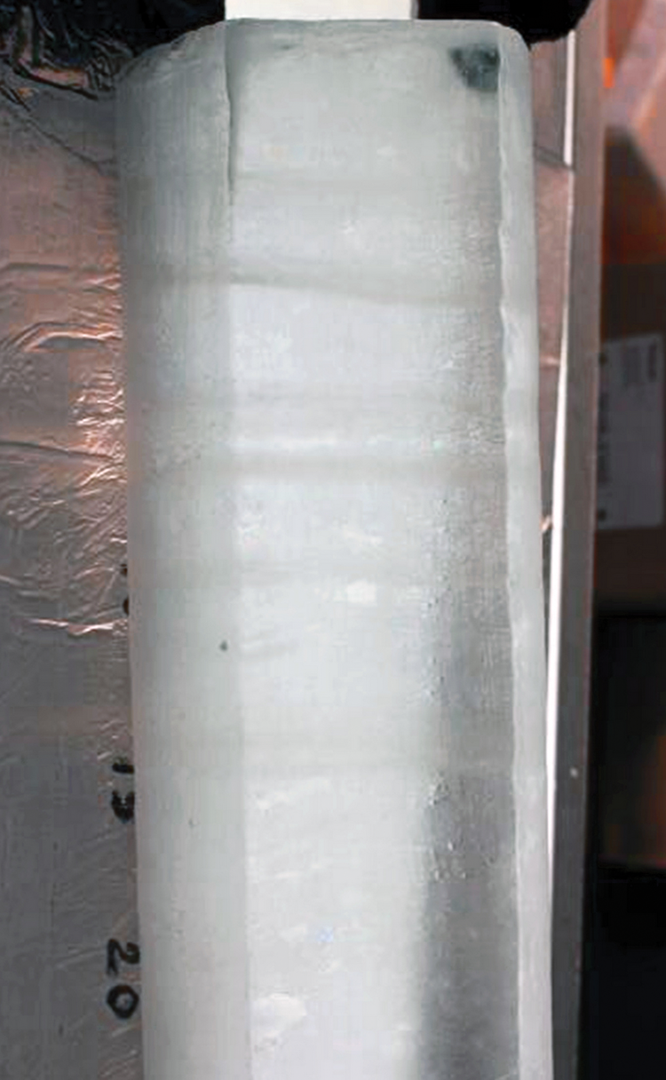
Fig. 7. Ash layers in the 5G-5 ice core used to anchor this new core on the 5G-1 ice core logging depth taken as reference.
The drilling of the 5G-5 hole was stopped on 28 January at a depth of 3320 m.
The measurements of the new 5G-5 hole's inclination angle (Fig. 8) showed that, at the depth of the volcanic ash layers, the angle between the axes of holes 5G-1 and 5G-5 does not exceed 0.8°. Therefore, with the total length of borehole 5G-5 from the sidetracking point being 44 m, the distance between the axes of both boreholes at the depth of the volcanic ash layers (3311 m) is about 550 mm, which is close to what was originally planned.
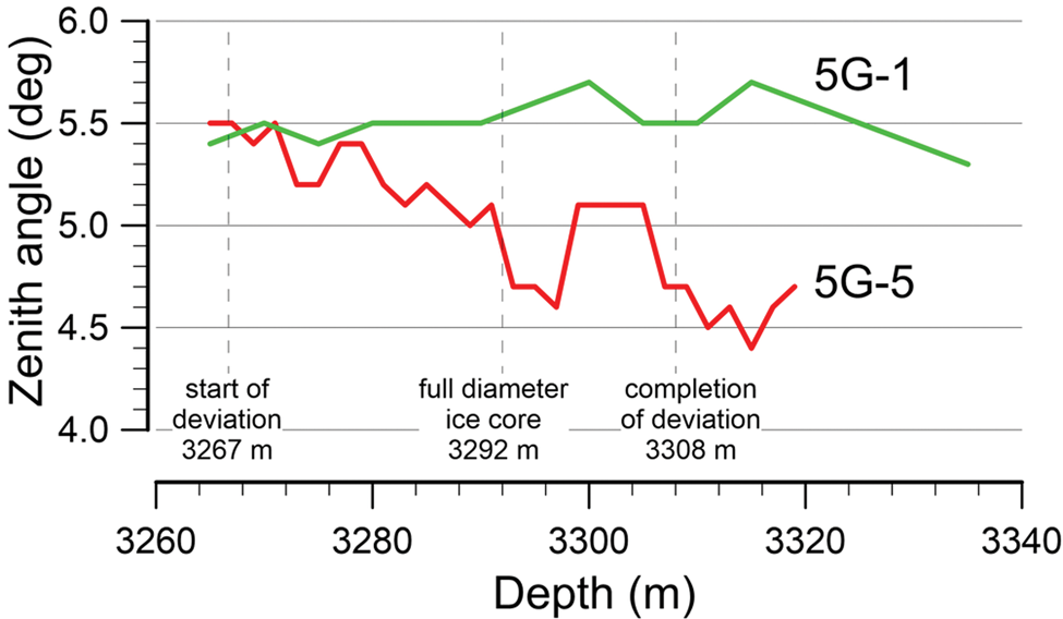
Fig. 8. Inclination of boreholes 5G-1 and 5G-5 within a depth interval of 3265–3320 m.
Summary
Based on the case of the 5G-5 hole drilling at Vostok Station, we have described the method and operating procedures for replicate coring at a targeted depth in a slant hole using a standard cable-suspended electromechanical drill. This simple and reliable method for multibranch hole drilling was designed at the St. Petersburg Mining University. It is applicable for boreholes even with a small inclination angle (1–2°) which still allows the drill apex to rest on the downhill side of the borehole.
After the deviation has been made, the parent hole becomes lost for geophysical logging and/or continuation of drilling operations with standard borehole tools. Nevertheless, the obvious advantages of the described method are:
1) the use of a standard electromechanical ice coring drill with only minor modification to its cutter head;
2) minimal additional cost and time required to perform the sidetracking operation.
The method has been successfully used in the deep Vostok 5G-1 borehole twice. In the 2008/09 austral season, a sidetracking was initiated to bypass the drill lost in the 5G-1 hole. In the 2018/19 season a new deviation from the 5G-1 hole was made with the aim of obtaining a replicate core of old meteoric ice. The drilling of the new 5G-5 branch-hole will be continued during two coming field seasons to a depth of about 3610 m in order to obtain a continuous ice core aged from 400 to 1200 ka, as well as to replicate sampling of an ice layer containing mineral inclusions of the Lake Vostok bottom sediments bedded at ~3607 m.
Acknowledgements
This work was financially supported by the Russian Science Foundation, grant no. 18-17-00110. Logistic support for the drilling operation at Vostok Station was provided by the Russian Antarctic Expedition. The authors thank Alice Lagnado for English editing of the manuscript and two anonymous reviewers whose valuable comments helped to improve the paper.


 Open access