

Introduction
Flexural behaviour of ice covers is an important factor in establishing their bearing capacity and ice loading on structures. It has application in studying natural ice processes such as ridge building, ride-up, pile-up and rubble building. Accurate determination of flexural properties of an ice cover is therefore essential. Usually such determinations are made from in situ cantilever beam tests. Flexural strength and apparent elastic modulus are calculated by means of simple elastic beam theory, which assumes that ice is isotropic and homogeneous, that the root of the beam is rigidly clamped and that there is no buoyant support of the beam by water. None of these assumptions is completely valid however. When cantilever beam tests are analysed using simple elastic beam theory, spurious results may be obtained if the length-to-thickness ratio, width-to-thickness ratio, and loading rate are not taken into account.
Some attention has already been given to the influence of these factors on the analysis of the results of cantilever beam tests. Määttänen (1976) studied beam geometry and loading rate effects during a field test carried out in the Baltic, finding a decrease in strength and modulus with increasing ratio of beam width to ice thickness. Beam length had no effect on flexural strength, but modulus decreased with decreasing length unless the effect of shear was eliminated. Frederking and Häusler (1978) evaluated the influence of buoyancy on strength and modulus of sea-ice beams. Analytical and experimental results of this investigation suggested that buoyancy effects could be ignored provided the ratio of beam length to ice thickness was less than ten.
When Svec and Frederking (1981) examined the influence of plate effects at the root of a cantilever beam they found that for a length-to-thickness ratio of ten about 20% of the deflection at the tip of the beam is due to rotation at the root. Moments in the root area are about 50% greater than those determined from simple beam theory. Tatinclaux and Hirayama (1982) recently presented a technique for determining modulus from strength test data on cantilever beams of various lengths. This paper presents the results of a series of tests on the effect of beam geometry and loading rate on measured strength and modulus values, plus an analysis of the results in terms of available theories for cantilever beams.
Test Procedure
The tests were performed on two sheets of freshwater ice grown in a large refrigerated tank (21 × 7 m in area and 1.2 m deep) in the Hydraulics Laboratory of the National Research Council Canada (Pratte and Timco 1981). The extent of the ice, about 130 m2, allowed a large number of tests to be performed. The water was mixed with air bubblers until it cooled to a uniform temperature of 0.1°C, and was then seeded using a fine water spray at -18°C ambient temperature. Subsequent ice growth was at an air temperature of -12°C. This produced fine-grained columnar ice of type S-2. Grain size varied from about 1 mm at the top to about 3 mm at the bottom of the ice sheet, which was 60 mm thick; grain structure was similar for both sheets. The ratio of sample width to grain size was always greater than 20:1, thereby minimizing grain-size effect.
The beam tests were carried out in situ in the ice cover. Beam dimensions were laid out with a marking pen and then cut with an electric chain saw, care being taken to keep water off the beam surface during cutting, particularly at the root where final cutting was done by hand. Room temperature during the tests was -10°C. A thermocouple frozen into the ice cover indicated an average ice temperature of -3°C. For ice sheet 1 (series 1) the ice thickness was, on average, 61 mm; for series 2, about 4 h later, ice thickness averaged 71 mm. For ice sheet 2 (series 3) the ice thickness was 40 mm; for series 4, about 18 h later, the ice thickness was about 64 mm.
Load was applied to the end of the beam through a load cell with a hand-operated rack-and-pinion drive clamped to the side of the service carriage. The rate at which load was applied could be varied, but for the majority of the tests every effort was made to achieve the same rate. The tip displacement of the beam was measured with a displacement transducer of the DCDT type supported on an independent beam spanning the tank. Load cell and displacement transducer readings were recorded on a two-pen strip chart recorder to produce records of load time and displacement time. They were also fed into an X-Y recorder to produce curves of load versus deflection. After each test the dimensions of the beam were measured. Elastic beam theory was used to calculate flexural strength σ sband elastic modulus E sb:
where P’ is breaking load, L is beam length, w is width, h is ice thickness and P/y is the slope of the load-deflection curve. Note that y is the actual measured tip deflection. P/y and Fsh were only evaluated for cases for which the load-deflection curve was linear to break.
Results
Test results are summarized in Tables I to III. Altogether, six test series were performed: series 1 to 4 on beam-length effects, series 5 on the influence of loading rate, and series 6 on beam-width effects. Flexural strength as a function of normalized beam length for the two ice sheets is plotted on figures 1 and 2. For ice sheet 1 there is no significant dependence of strength on beam length. Series 1, with an average ice thickness of 61 mm, had a mean strength of 860 ± 200 kPa and series 2 a strength of 870 ± 210 kPa for an average thickness of 71 mm. The similarity of the strengths for the two ice thicknesses and the relatively large standard deviations show that there is no significant difference for the two test series.
Table 1. Results Of Cantilever Beam Tests On Ice Sheet 1: Beam-Length Series

Table 2. Results Of Cantilever Beam Tests On Ice Sheet 2: Beam-Length Series

Table 3. Results Of Cantilever Beam Tests On Ice Sheet 2: Loading Rate And Beam-Width Series


Fig. 1. Flexural strength versus ratio of beam length to ice thickness for ice sheet 1.

Fig. 2. Flexural strength versus ratio of beam length to ice thickness for ice sheet 2.
Strengths for ice sheet 2 are presented in Figure 2. The average flexural strength of test series 3 and 4, ice thickness 40 and 60 mn, respectively, for short beams (ratio of beam length to ice thickness less than 10) was 740 ± 120 kPa and 660 ± 110 kPa. The difference between the two mean values is not significant. On the other hand, the difference in strengths for the two ice sheets is just on the verge of being significant.
As the load-time curves were generally quite linear, strength data were examined in terms of time to failure. Flexural strength as a function of time to failure in sheets 1 and 2 is presented in figures 3 and 4, respectively. In both cases there is a general trend towards increasing strength with increasing loading time.

Fig. 3. Flexural strength versus time to failure for ice sheet 1.

Fig. 4. Flexural strength versus time to failure for ice sheet 2.
Elastic moduli calculated by means of Equation (2) are plotted in figures 5 and 6 for ice sheets 1 and 2 respectively. Both sets of results show that the calculated moduli decrease with decreasing beam length. There is no significant difference in the results for the four series. The marked dependence of the modulus on beam length shows that the simple cantilever beam theory is not valid for this application.
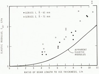
Fig. 5. Elastic modulus versus ratio of beam length to ice thickness for ice sheet 1 showing comparison of experimental results and apparent elastic modulus predicted using Equation (15).
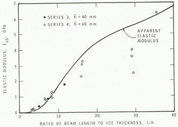
Fig. 6. Elastic modulus versus ratio of beam length to ice thickness for ice sheet 2 showing comparison of experimental results and apparent elastic modulus predicted using Equation (15).
Tests were carried out over a range of loading rates, equivalent to strain-rates of 10 -4 to 10 -3 s -1, to see whether rate had any effect on strength or modulus (series 5). The dependence of strength on the time to failure is presented in Figure 4. No dependence of strength on loading rate is apparent. Elastic modulus calculated using simple cantilever beam theory (Equation (2)) is plotted against loading time in Figure 7. It may be seen that the modulus tends to decrease with increasing loading time.

Fig. 7. Elastic modulus as a function of loading time.
A series of tests was carried out on ice sheet 2 to investigate the effect of beam width on flexural strength and modulus. These results are plotted in Figure 8. Selected results from the loading rate series have been included to provide a more complete range of widths. Both strength and modulus were found to decrease with increasing width.

Fig. 8. Elastic modulus and flexural strength as a function of beam width (h = 66 mm), showing comparison of experimental results and apparent elastic modulus predicted using Equation (15).
Discussion
Interpretation of results of in situ cantilever beam tests is known to be subject to error due to rotation and deflection of the beam at the root, shear effects, and buoyant reaction of water. The relative influence of these factors is a function of beam geometry as well as elastic properties. Shear is proportionally more important for short beams. Long beams with a low elastic modulus are more influenced by buoyancy. Wide beams behave snore as plates and are consequently stiffer.
Quantitative expressions for the influence of the preceding factors will now be presented. Interpretation of the modulus results will be considered first because they show a strong geometry influence. The total measured deflection y at the tip of an in situ cantilever beam is the sum of
where ysb is the tip deflection of a simple cantilever beam (Equation (2)), α a factor to take into account the influence of buoyancy, ys deflection due to shear, yp deflection due to rotation at the root, and yp deflection of plate at root. Note that the term y« is considered here only because beam deflections were measured with respect to the tank wall. If measurements were made in relation to the ice cover at the root of the beam this term would drop out.
Tatinclaux and Hirayama (1982) simplified the equations for buoyant effect on stress and deflection; the following equations were shown to be excellent approximations over the indicated ranges

where σSb and ySb are flexural stress and tip deflection of a simple in situ cantilever beam and o0 and yb are actual values, taking into account the contributions of buoyancy. λ is defined as
Where γW is weight density of water, E is elastic modulus, and his ice thickness. The buoyancy factor a in Equation (3) is defined in Equation (5).
Roark (1965: 129-130) presented the following equation for the deflection due to shear in a cantilever beam where G is shear modulus. For an isotropic material shear modulus is related to elastic modulus hy the relation

where v is Poisson’s ratio. Columnar-grained ice is best characterized as transverse isotropic. Investigations by Sold (1958) showed the relation between strains in the plane of the ice cover to be complex. For example, Poisson’s ratio increased from 0.3 to 0.6 as strain increased. In subsequent analysis in this paper it will be assumed that the relation between shear modulus and elastic modulus is determined by v = 0.3.
Using a finite element analysis Svec and Erederking (1931) found tip deflection to be 20% greater due to rotation of the beam at the root. Because each beam in this test program had a different geometry it is not feasible to use the finite element technique to evaluate root rotation for each test. As an approximation, an equation developed by O’Donnell (I960) for in-plane loading of a cantilever beam elastically connected to a semi-infinite plate has been used. The expression for the root rotation, θΔγ is The corresponding tip deflection yr is given by
Plate deflection at the root can be approximated from the deflection of a semi-infinite plate subjected to a line load at its edge. This problem was solved by Reference NevelNevel (1965). The deflection under the centre of a line load is given by
Mote that line load length, i.e. beam width, does not appear in Equation (11), which is a good approximation (within ± 3%) for beam widths up to 1m for the ice thicknesses and modulus values of these test series. To simplify, Equation (11) can be written in the form
Substituting the above expressions in Equation (3) gives
A typical case will be considered to give an appreciation of the relative importance of the various deflection terms. Assuming E = 6 GPa, v = 0.3, h = 0.06 m, L = 0.48 m, w = 0.12 m,γW = 104 N m-3 and P = 200 N, the total deflection was calculated to be 3.34 mm. Of this total 80% was due to deflection at the root, 17% to deflection of the cantilever beam, 3% to rotation at the root, and a negligible amount to shear and buoyancy effects. These proportions will, of course, change with beam geometry and elastic properties. The calculated deflection is similar to deflections measured under similar conditions in these tests.
Equation (15) can be rearranged to solve for elastic modulus as a function of the slope of the load-deflection curve:


An iterative procedure has to be used to solve for elastic modulus from Equation (16), since E also appears on the righthand side of the equation in a and. β As this solution for E is rather time-consuming, it was not used for evaluating elastic modulus for all the tests.
To demonstrate that Equation (15) represents the observed dependence of deflection on beam geometry, an assumed set of conditions was used to calculate an apparent elastic modulus, i.e. a modulus calculated by substituting the tip deflection y calculated from Equation (15) into Equation (2). These curves of apparent elastic modulus are plotted in Figures 5, 6 and 8. The conditions assumed were E = 6 GPa, v = 0.3, h = 60 mm, w = 120 mm for the beam-length series, and L = 480 mm for the beam-width series. The values for the elastic properties E and v were estimated using the approach of Reference SinhaSinha (1979). It may be seen that the trends of the apparent elastic modulus predicted using Equation (15) closely follow the experimental data.
The elastic modulus decreased by about 20% as loading time (actually time to failure) increased from about 0.5 to 8 s. A similar trend was observed in the experiments of Traetteberg and others (1975) and in the theoretical predictions of Reference SinhaSinha (1979).
Results of tests on flexural strength showed only a small dependence on beam length. This is not surprising since, with the relatively high modulus of the ice, the buoyancy effect is very small. When Equation (4), as developed by Tatinclaux and Hirayama (1982), was applied to the conditions of series 4 (E = 6 GPa, h = 60 mm, σb= 660 kPa), the curve for apparent flexural strength shown in Figure 2 was obtained. The decrease in flexural strength with increasing beam width (Fig. 8) is similar to the finding of Määttänen (1976) in field tests. Similarly, Lavrov (1971:88) in laboratory cantilever beam tests on freshwater ice found the flexural strength to decrease by 24% with an increase in the width to thickness ratio from 1 to 2. At the present time, however, no explanation is available for such a strength trend.
There is a fundamental question whether the cantilever beam test is a true measure of the flexural strength of ice due to stress concentrations at the root of the beam. The presence of such concentrations has been demonstrated both experimentally and analytically by Maättänen (1976) and by Svec and Frederking 11981). When Gow and others (1978) carried out an extensive series of in situ tests on both cantilever and simply supported beams, they found that the flexural strength of simple beams was as much as 1.7 times greater than the strength of the corresponding cantilever beams. This difference was attributed to the effect of stress concentration.
Concurrently with the tests carried out for this paper, a series of comparative strength tests was carried out on ice from the same sheets (Timco and Frederking 1982). Small beams were cut from the full thickness of the ice cover, cooled to a uniform temperature of -10°C, and tested in a small test machine. The strength of these beams under simple support and with the top surface of the ice cover in tension was 2 200 ± 320 kPa. Direct comparison of the results is not possible because of the difference in temperature and test conditions, but the simple beams had substantially higher flexural strengths than the cantilever beams. Undoubtedly stress-concentration effects are present in the results of the tests on cantilever beam strength. This concurs with the recommendations of the Committee on Ice Problems of the International Association for Hydraulic Research (Schwarz and others 1981) that cantilever beam tests should not be considered at this time to give true flexural strength values for an ice cover, but rather index values. Nevertheless, such index values are useful for comparison of relative flexural strength of ice in nature at different locations and, provided certain geometrical constraints are observed, comparisons of flexural strength of ice in a model basin with ice in nature.
Flexural strength results in figures 3 and 4 show a trend towards increasing strength with increasing time. It is probable that the initiation of flexural failure is controlled by the presence of flaws in the ice. If there is a large flaw or a large number of small flaws, the beam will fail at a lower stress and in correspondingly shorter time. Test series 5, in which loading times were varied, showed an entirely different trend for strength versus time to failure. In this case strength only increased slightly, while time to failure increased by an order of magnitude. This increase in strength could be due to the partial development of a plastic moment at the longer loading times.
Conclusion
The results presented in this paper are for finegrained, columnar, freshwater ice with relatively high elastic modulus. Although quite long beams were used (length-to-thickness ratios up to 35:1), little influence of buoyancy on flexural strength was observed. On the other hand, there was a significant decrease in flexural strength with increasing beam width. Flexural strength from cantilever beam tests cannot, therefore, yet be interpreted as the true flexural strength of an ice cover because of inability to explain these variations.
No systematic influence of loading rate on flexural strength was observed, but elastic modulus decreased with increasing loading time, as would be expected. Elastic modulus showed a very significant dependence on beam geometry. Modulus increased with increasing beam length-to-thickness ratio and decreased with increasing beam width-to-thickness ratio. An analytical expression for total beam deflection, taking into account buoyancy, shear, rotation and deflection at the beam root, was developed. When it was applied to the test results, it explained satisfactorily the influence of beam length and beam width. In particular, it showed that because beam tip deflection was measured relative to the tank wall a large component of the measured beam deflection was due to plate deflections at the root. If this factor were to be neglected, the apparent elastic modulus could be 1/3 to 1/4 of the real value. It might explain the low elastic modulus values obtained from beam tests in some ice model basins. Great care must be taken in determining elastic modulus from observations of beam deflection to ensure that all factors contributing to the measured deflection are taken into account.
Acknowledgement
This paper is a contribution from the Division of Building Research, National Research Council Canada, and is published with the approval of the Director of the Division.


