

Introduction
One of the most significant scientific challenges of our time is to develop a better understanding of the Earth‘s climate. Accessing the records of past climate changes captured in the polar ice sheets is a critical step for scientists working to meet this challenge. Scientists have developed powerful techniques to read these records using both ice cores and borehole measurements, but they are challenged by very short field seasons on these ice sheets and the years-long process of gathering deep ice cores.
The replicate ice-coring system developed by the Ice Drilling Design and Operations (IDDO) group at the University of Wisconsin for the US National Science Foundation is a breakthrough technology for these scientists. The replicate coring system is a steerable drill that can create a sidetrack or deviation at any target depth and any target azimuth in an open borehole. This is a significant advance in ice coring, where replicate coring deviations up until now have been limited. Previous ice-drilling deviations have been performed with material blocking the parent borehole functioning as a whip-stock or in open holes on the low side, or the floor of an inclined borehole. Previous ice-drilling deviations include successes at Vostok station, Antarctica (Reference Vasiliev and TalalayVasiliev and others, 2011), and at North Eemian (NEEM), Greenland (S.B. Hansen, unpublished information). In exploration drilling in rock, similar systems also typically deviate from the low side in open holes (e.g. the DeviDrillTM system; Reference TokleTokle, 2000). The replicate coring system has demonstrated a critical new advantage for scientists in its ability to retrieve replicate ice core in an existing borehole at any targeted azimuth, including the high side of a borehole with inclinations as high as 6° from vertical. This allows logging tools guided only by gravity to continue to access the entire length of the parent borehole. Additionally, multiple replicate cores can be collected at any targeted depth from a single existing parent borehole, saving the considerable time and logistical expense of creating new boreholes.
The replicate coring system was designed and tested from 2010 through 2012 and deployed in December 2012 to the West Antarctic Ice Sheet (WAIS) Divide. The 164 mm diameter parent borehole at WAIS Divide was created from 2007 to 2012 with IDDO‘s deep ice-sheet coring (DISC) drill (Reference Mason, Shturmakov, Johnson and HamanMason and others, 2007; Reference Mortensen, Sendelbach and ShturmakovMortensen and others, 2007, Reference Mortensen, Johnson and Shturmakov2014a; Reference Shturmakov and SendelbachShturmakov and Sendelbach, 2007; Reference Shturmakov, Lebar, Mason and BentleyShturmakov and others, 2007). With the replicate coring system, the IDDO drill team successfully created five deviations from the 3405m deep parent hole, collecting a total of 285 m of replicate core from the most interesting time periods in the WAIS Divide climate record (http://www.icedrill.org). Figure 1 shows the replicate coring system in operation during the 10 week production season at WAIS Divide.

Fig. 1. The replicate coring system in the drilling arch at WAIS Divide: 1 : downhole sonde (see also Figs 2 and 4); 2: ice-chip barrels at cleaning station; 3: centrifuge for removing drill fluid from ice chips; 4: crown sheave on tilting tower assembly; 5: cable level wind assembly; 6: 4000 m winch.
Overview of Operation
A description of the major sections of the downhole portion of the drill, the sonde, is essential to understand the basic operation of the system (Fig. 2). The cable interface section is the uppermost portion of the sonde and includes a freely rotating connection to the drill cable. Below this are the two actuator modules on either end of the instrument section. The actuator modules each include three levers to tip the drill in the borehole. Onboard electronics are contained within the instrument section, providing power and controls to the actuator modules as well as the pump and cutter motors just below the lower actuator. Chip barrels collect ice chips created from drilling. A core barrel is added as needed to collect and support the ice core. Multiple styles of cutting head are employed for the various requirements of the replicate coring operations. The functions and design of each section are provided in more detail below.

Fig. 2. Replicate coring system sonde.
The architecture of the replicate coring system maximizes the amount of flexibility in operation, while adjustable design parameters focus and simplify operation. In production operation, the operator inputs geographic direction and the amount of force to be exerted on the bore wall. Sensors on board provide real-time feedback of rotation, torque, weight-on-bit and inclination to the operator. On-board controls make near-instantaneous adjustments to maintain the commanded force and direction.
Through laboratory and field testing and a 10week production season, a detailed procedure has been developed to efficiently create a deviation in three basic steps (Reference Johnson, Mortensen, Gibson, Goetz and ShturmakovJohnson and others, 2014; Reference SlawnySlawny and others, 2014; Fig. 3).

Fig. 3. Replicate coring deviation procedure presented as three basic steps. First, the deviation is commenced using the broaching head (A). Upper and lower actuators extend on opposing sides (blue arrows) to tip the sonde and engage the cutter. The broaching cutter engages the ice wall, removing material in repeated passes in an upward stroke (B). In the second step, the milling cutter is installed and a flat landing surface is created (C, D). In the third step, a coring cutter and core barrels are added. The sonde is again tipped and coring starts on the flat surface provided by the milling cutter (E). The first partial core has a tapered geometry (F). This core is broken by core dogs and removed as the sonde begins to ascend.
First, a deviation of ∼15 m in length is created by cutting in an upward stroke using a broaching cutting head (Fig. 3a). The cut is expanded in repeated passes until it is deep enough to allow the sonde to move 75–100 mm in a radial direction out of the parent borehole. An inclination sensor with <0.1° accuracy is used to make this measurement. Although using a milling cutter to create the deviation may be possible, using an axial cutter like a broach efficiently removes the material of the deviation with an inherently straight cut. This approach, however, leaves a gradual slope at the lower end of the deviation, which is not suitable for landing the coring head.
The second step in cutting the deviation is to create a landing for the coring head and this is accomplished by rotary cutting with a milling head over an additional 1 m depth (Fig. 3c and d).
Finally, the coring operation can commence. The sonde is tilted into the deviation to an angle of 1° relative to the parent borehole. An inclination sensor with <0.1° accuracy is used to make this measurement and ensures that the cutter lands at the full radial depth of the deviation (75–100 mm). The first core is 1 m in length and the cross section of the bottom of the core is nearly a full replicate core diameter (108 mm); this ensures that the core dogs can engage to break the core (Fig. 3f).
Subsequent cores are recovered by re-entering the deviation. Accurate inclination and depth readings are essential to ensure smooth re-entry. Radial force provided by the lower actuator is not necessary once engaged in the deviation to the depth of the base of the first core. At this point, the lower levers are retracted and the upper levers remain extended to provide anti-torque. The upper levers transition from the parent to the replicate borehole by first coring to the point of transition with a 2 m barrel. On the following run, the 1 m barrel is used, allowing the upper levers to descend fully into the replicate borehole before coring is resumed.
Mechanical Design Replicate Subsystems
The implementation of the replicate coring system at WAIS Divide required the development of several new subsystems. Additionally, critical portions of the DISC drill underwent significant redesign to meet the requirements of deviating out of the parent hole (Fig. 2).
Cable interface section
The cable interface section includes a mechanical fuse attaching the multi-conductor and fiber-optic cable to the sonde. Also, within this section are temperature and weight-on-bit sensors, along with optical and electrical slip rings allowing the sonde to rotate freely. The anti-torque blades mounted to this section in DISC drill operation are removed for replicate coring, reducing the effective diameter and allowing the top of the sonde to move more freely in the borehole. The actuator levers provide anti-torque for the replicate coring system during both deviation and coring.
Upper and lower actuator sections
The upper and lower actuator sections include the mechanism to exert force on the wall of the borehole to steer and anti-torque the drill. Each 134mm diameter housing, machined from UNS S30400 stainless steel, contains three identical mechanisms to drive three levers.
Each mechanism is driven by a Maxon 40 mm diameter 150W brushed d.c. motor with a 230:1 planetary gear reducer (Fig. 4, item 2). A 19 mm ball screw (Fig. 4, item 7) provides additional mechanical advantage and a high-efficiency conversion to linear motion. Each ball screw has a duplex pair of 50 mm angular contact bearings (Fig. 4, item 4) at its lower end, supporting the ball screw under tension of up to 10 kN during lever extension. At its upper end, each ball screw is supported by a single 50mm angular contact bearing, accommodating smaller loads on retraction.

Fig. 4. Replicate coring system actuator section: 1: pressure-compensating piston; 2: gear motor; 3: LVDT; 4: angular contact bearing; 5: anti-torque-style lever end; 6: actuator lever; 7: ball screw and nut assembly; 8: fail-safe shear pin; 9: stabilizer ring; 10: LVDT axial seal; 1 1 : rotary shaft seal. The scale in the inset is 2 : 1 .
The ball screws are open to drilling fluid during operation. Consideration was given to sealing the mechanism to prevent clogging with ice chips. The design implemented favored simplicity, with the standard nylon brush used at the top of the ball nut and a slip-fit bushing at the bottom preventing most chips from entering. In production, there was a minimal amount of cleaning maintenance required after weeks of operation, partially due to freezing condensation while on the surface.
As shown in Figure 3, the ball screw drives the lever (Fig. 4, item 6) through a linkage that includes UNS N02200 nickel fail-safe shear pins (Fig. 4, item 8) sized to shear at twice the 1000N maximum operating load at the lever. At this size, the shear pins provide a 2 × safety factor for the mechanical cable fuse in a condition where up to four levers fail in an extended position. The shear pins also address an inherent risk of overloading the actuator assembly when traversing through the changing geometry of a deviation with levers extended. The shear pins function to prevent damage to other components of the assembly in these situations.
The geometry of the three levers of each actuator is critical to the function of the system. Two different lever styles are used and are easily changed to suit the requirements of a particular situation (Fig. 5). The first style is typically installed on the lower actuator and contains a disk that contacts the wall off-center. This facilitates smooth movement of the levers tangent to the bore wall, allowing the sonde to move to an inclined position. This lever geometry also allows the sonde to slide smoothly up and down the borehole, minimizing axial stick–slip. The second lever-end geometry includes a blade to serve the critical function of anti-torque for the cutter motor. The blade is mounted on rollers, with its axis aligned tangent to the bore wall, again minimizing axial stick–slip.

Fig. 5. The replicate coring system actuator sections showing the two styles of lever used for production drilling. (a) Anti-torque-style levers include sharp blades mounted on rollers. (b) Disk-style levers allow smooth movement in directions both vertical and tangent to the borehole wall.
The forces of just two levers of each actuator are combined to provide the net force and direction commanded by the operator. To achieve an accuracy of net force of ±15° azimuth, performance of each lever mechanism is monitored and calibration performed. Calibration is performed as needed, typically after several days of 24 hour operation, with the sonde on the tower. This entails measurement of force vs supplied current for each of the levers, using a load cell with integrated display from Proctor and Chester Measurements Ltd. Calculated offset and slope values are entered by the operator to update the on-board navigation system. Examples of calibration values are plotted in Figure 6, clearly showing the linear relation between motor current of the d.c. brushed motor and output force, as well as the degree of variation between each of the individual lever mechanisms tested.

Fig. 6. Lever calibration data showing the linear relation between motor current of the d.c. brushed motor and output force. The twelve curves also show the degree of variation in the performance of the three levers on each of the four actuator modules.
In addition to the slope and offset values, the navigation system uses a look-up table of skew values to account for the change in mechanical advantage of the lever as it is extended (Fig. 7). To implement these values, a lever position sensor is also contained in the actuator housing. A spring-loaded probe on a MacroSensor linear variable differential transformer (LVDT) rated for 34MPa reliably monitors this lever extension (Fig. 4, item 3).

Fig. 7. Lever skew data representing the change in mechanical advantage of the lever as it is extended.
While the ball screw mechanism is open to the drill fluid, the gear motors and LVDT are immersed in ∼1.5 L Aeroshell Fluid 4 hydraulic fluid, ensuring proper lubrication of the gear motor and eliminating any concern about melting ice chips. This section of the actuator module is pressure-compensated with a 100 mm diameter aluminum bronze piston (Fig. 4, item 1) containing spring-energized V profile PTFE seals translating ∼25mm in a UNS S41600 stainless-steel housing. The pressure compensation reduces the demands on the seals, including the similar spring-energized V profile PTFE rotary seals (Fig. 4, item 11) at the ball screws and axial seals (Fig. 4, item 10) at the LVDTs. The rotary seal assemblies in particular proved lacking, allowing a small amount of air to leak into the pressure-compensated section. During the test season this resulted in motor failures apparently due to combustion of the oil at the commutator. Careful reassembly, new seals and maintenance prevented any recurrence of the failure during the production season.
Stabilizer rings above and below the levers (Fig. 4, item 9) limit deflection of the sonde and enhance inclination during deviation operations. Additionally, when used in conjunction with stabilizer pads on the screen barrels, the rings help to control trajectory when coring. Stabilizer rings are available in a range of diameters and can be located on each actuator, the cutter head and the anti-torque section.
Instrument section
The instrument section is an air-filled pressure vessel containing the fiber-to-copper transceiver, controls and power supplies for the drill motor, pump motor and actuator motors, navigation and other internal sensors, as well as processing capabilities for all sensors on the sonde. The most significant electrical modifications for replicate coring are presented by Reference Mortensen, Goetz, Gibson, Johnson and ShturmakovMortensen and others (2014b). Mechanical modifications to this section for the replicate coring system, however, are minor. A new bulk head is used to accommodate an additional high-pressure connector for communication and power to the actuators. Mounting accommodations are also added for the replicate coring module, the sensor board and the improved navigation package.
Pump motor section
The pump motor section contains two motors, one to drive the cutter rotation and the other to drive the chip transport pump. The pump itself is also contained within this section as are bearing assemblies and the coupling to the lower sonde. While the functions of the motor and pump for replicate coring are essentially unchanged from those of the DISC drill, two critical changes are made to the housing.
First is the change to a compatible threaded interface to accommodate the new barrels described below. This change was made with minimum impact to the existing DISC drill design.
The other critical modification is a broadening of the stance of the paired bearings supporting the increased loads due to bending forces exerted on the sonde by the actuators. The improved spacing nearly triples the capacity of the bearings to withstand these bending forces. The modification provides ample strength for all replicate coring operations and improves the overall stiffness of the sonde (Fig. 8).

Fig. 8. The larger motor-bearing stance of the replicate drill system versus the DISC drill accommodates the bending loads of deviation operations.
Chip and core barrels
The outer barrels of the chip collection and the core barrel sub-assemblies are industry standard style PWT casing tube (Fig. 9), typically used in exploration drilling, with a 140 mm outside diameter and 6.35 mm wall. This thin walled tube allows reuse of the existing inverted water well screens of the DISC drill despite the fact that the replicate borehole at 148mm diameter is 16mm smaller than that of the DISC drill. By maintaining the chip volume and reducing the core diameter, the screen barrel length of the replicate coring system is reduced by 15% for an equivalent core length of the DISC system. A short screen barrel is critical to reduce deflection under radial actuator loads during replicate deviation. To minimize total screen barrel length, a suite of barrel lengths is available to accommodate from one to six 0.75 m long screens, as necessary for a specific operation.

Fig. 9. The replicate coring system uses off-the-shelf PWT casing tubes for the outer core and screen barrels. These thin-walled tubes have a smaller outer diameter than those of the DISC drill but allow the use of the same screen barrels.
The barrels provide an acceptable run-out of 0.076 mm over a 2 m section as machined in the final assembly. In addition, this off-the-shelf tubing offers a field-proven and optimized thread design, as well as a cost saving over custom approaches.
Mounted at the base of the screens is a check valve preventing chips from falling out during ascent, while maximizing the free flow of fluid during tripping in both directions. The check valve design used in DISC, a flapper valve complemented by reed valves for bypass flow, is suitable for the large chips created by broaching (Reference Mason, Shturmakov, Johnson and HamanMason and others, 2007). Collecting chips in deviation operations is complicated by the relatively large open area around the cutter head as the cross section of the hole is expanded. Drill runs dedicated to filtering chips are required to keep the borehole clean during deviation operations. Chips are recovered not only at the depth of the deviation but also above or below, dependent on the density of the chips relative to the local drill fluid density.
Cutter heads
The replicate coring system includes several cutter heads each with threaded ends for mounting to the core or screen barrels (Fig. 10). The first two cutter heads discussed below are designed for the function of creating a relief or slot in the wall of the parent borehole to begin the deviation.

Fig. 10. The cutter heads used in production: broaching (a), milling (b) and coring (c). The inset (d) shows the critical serrated edge of the broaching cutter created by knurling the cutter before heat-treating. The white arrow in (b) identifies one of the six scoop cutters on the milling head.
The milling head (Fig. 10b) cuts ice primarily through rotation, similar to a typical coring head, but it cuts ice across its full 148 mm diameter. The replicate coring system milling head is designed with a depth of cut to allow axial cutting as fast as 50 mms−1. This axial speed is limited practically by the amount of torque that can be accommodated in stable drilling. This relatively fast drill rate, however, is still within the range of speeds at which the sonde exhibits stick–slip. Stick–slip occurs at low speeds when the friction of the cable and sonde against the bore wall turns a steady pay-out (or pay-in) at the winch into an axial stop–start motion at the sonde. In stick–slip, the sudden advances of the sonde can exceed the cutting ability of a rotating cutter, resulting in spiral grooves or loss of cutter contact altogether. To lessen the impact of this result, down-facing scoops are included to cut away the threads of ice between the spirals. These scoops are shown between the radial aligned cutters in Figure 10b and are positioned at a diameter slightly less than that of the radial shoes. In order to facilitate its primary function of creating a sharp ledge at bottom of the slot, the milling head has cutter relief for radial cutting as well. Radial depths of cut of up to 2 mm can be achieved.
The broaching head (Fig. 10a) is the complement to the milling head in creating the slot for the deviation. A broaching cutter cuts axially by scraping, similar to a rasp, typically without rotation. It is inherently immune to the challenge of stick–slip described above. It also requires almost no anti-torque, minimizing the risk of precession and making a straight slot and stable cutting significantly more likely. The broaching cutter of the replicate coring system has been refined through laboratory testing to minimize required radial contact forces. This refinement has defined rake and relief angles and resulted in the addition of a serrated cutting edge. The edge serration is accomplished with a knurling tool on a lathe and greatly increases initial contact pressures on the ice. Combining the serration with some rotation using the sonde‘s existing cutter motor reduces the axial force required to engage the cutter by >50%. Three interchangeable cutters are available for the broaching head, with diameters of 155, 150 and 148mm, to optimize cutting in a variety of conditions.
The inherent advantages of the broaching head do bring some disadvantages. A significant disadvantage is that the broaching head creates a slot that has a gradually sloping bottom. This leaves a very difficult surface on which to land a coring head and is the primary reason for the use of the milling head.
The other disadvantage of the broaching head is that some means of disabling the cutter is required for tripping in or out of the hole; the sharp broaching cutter can engage and cut the borehole wall even with incidental contact. In the replicate coring system, the drop-ring–ratchet assembly addresses this problem. A ratchet and latch at the rotating joint of the motor section allows cutter rotation in the forward direction and the release of the ring only in the reverse direction. Upon release, the ring installed around the top of the screen barrel slides down the barrel driven by gravity to rest just above the broaching cutter. The sleeve has a 156mm outer diameter, slightly larger than the cutter, so it serves as a radial shoe preventing cutting in its lower position during ascent. Owing to the geometry of the sonde and its inclination relative to the borehole wall, the sleeve in its initial upper position does not contact the wall or interfere with cutting.
The coring head for the replicate coring system is based directly on the coring head and cutters for this DISC drill, which has provided excellent results (Reference Mason, Shturmakov, Johnson and HamanMason and others, 2007). For the replicate coring system the core is reduced to 108mm and the bore diameter to 148 mm. Also, UNS N02200 nickel shear pins are included as part of the assembly to help address the risk of a stuck cutter in a deviation.
Two additional cutter heads have been created for the replicate coring system as a contingency for recovering materials lost in the borehole. A downward-pointing conical tool allows material to be recovered in the cup created by the conical cutter in an initial pass. On a second pass, the core containing the cup and lost material is retrieved. A separate magnetic recovery tool recovers only magnetic materials.
Borehole camera
The borehole camera (Fig. 11) is used to monitor drilling progress and verify the quality of the deviation. It uses an off-the-shelf high-pressure camera in a custom assembly providing back-lighting, battery power and data storage. A real-time video feed system was implemented through the existing fiber-optic cable in field testing, but was changed to a stand-alone module installed in the core barrel shown in Figure 11 for production (Reference Shturmakov and SendelbachShturmakov and Sendelbach, 2007). Video data in the stand-alone module are recorded for download and displayed only after the sonde reaches the surface. The stand-alone camera system proved to be a significant advantage over the real-time system by simplifying installation and reducing the impact on production drilling time.
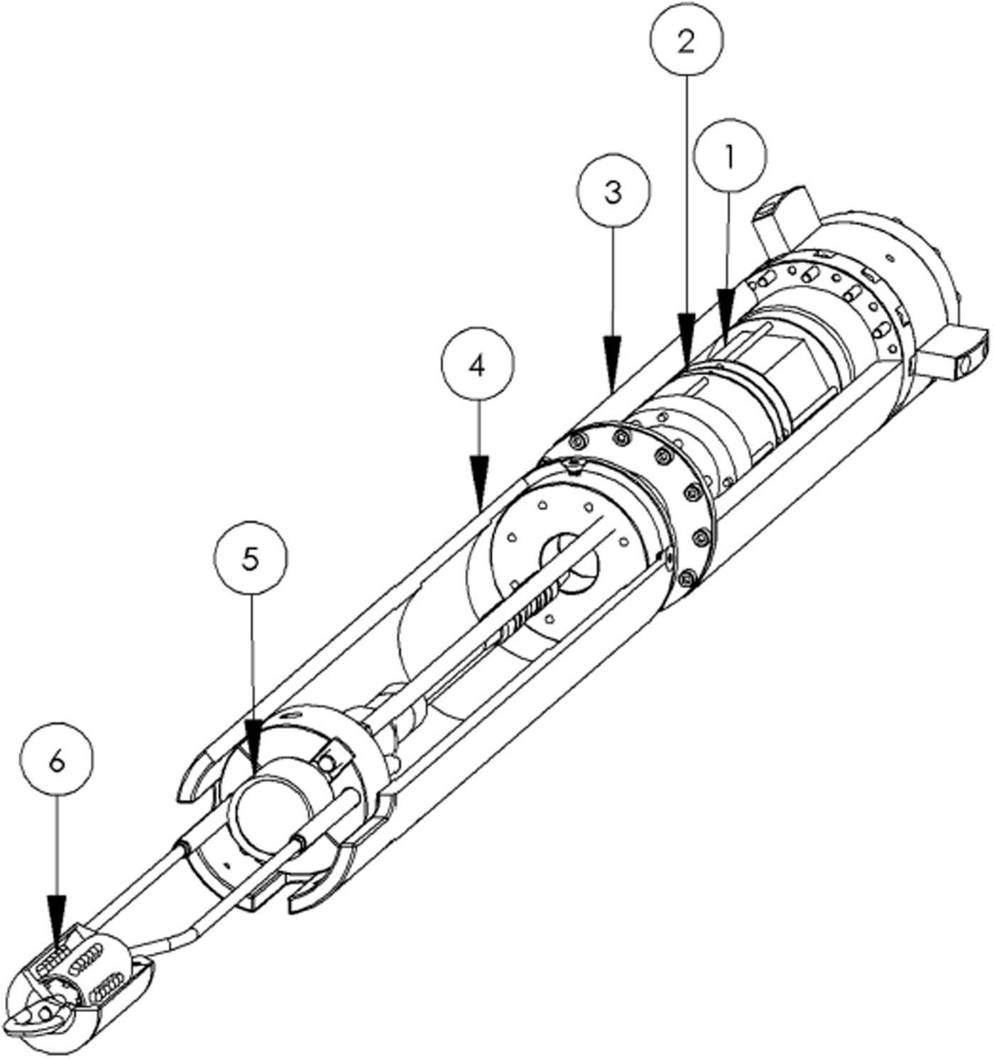
Fig. 11. The stand-alone borehole camera, which includes a rechargeable battery pack and on-board memory, allowing rapid deployment by securing the unit in the core barrel of the sonde: 1: battery pack; 2: electronics; 3: pressure vessel; 4: camera housing; 5: submersible camera; 6: LED back-light assembly.
A dummy logging tool is combined with the borehole camera for a final test of a successful deviation. The tool is essentially a 51 mm diameter steel rod with a 25 mm radius on its leading edge. It is attached with a 10 m cable on the eyelet at the lower end of the camera. The tool simulates a logging tool and is lowered through the parent borehole at each deviation to demonstrate that a logging tool can pass freely. Weight-on-bit is monitored to ensure that the 10 m cable remains tensioned and that the tool is unobstructed.
Surface equipment
The system includes four major surface operation subsystems, each of which requires only minimum modifications from the existing DISC drill system for use in replicate coring.
-
1. The chip-handling/fluid-recovery system is modified from the DISC drill to process cutting chips for the removal and recovery of drill fluid. For replicate coring, the screen barrel cleaning subsystem is modified to accommodate smaller-diameter barrels of different lengths.
-
2. The winch/tower, including 4000m of 15.2 mm diameter fiber-optic cable, is carried over from the DISC drill with minor modifications. A cable vacuum is added to minimize fluid loss at ascent speeds up to 2.2 m s−1. Also of note is that descent speeds are ∼1.0ms−1, similar to those with the DISC drill. The reduced fluid drag of a smaller-diameter drill is largely offset by the lower weight of the sonde in the replicate coring system.
-
3. The power and control system that provides an operator interface, electrical power and control for the sonde is significantly modified from that of the DISC drill, adding a new control interface for replicate coring (Reference Mortensen, Goetz, Gibson, Johnson and ShturmakovMortensen and others, 2014b).
-
4. The core transfer system has minor modifications from the DISC drill. The diameter of the fluid evacuation device, the device used to remove fluid from the core‘s surface, is reduced, and the core transfer turning fixture is modified to accommodate 1 m core barrels.
Summary
The newly developed replicate ice-coring system is a breakthrough for ice-coring science, allowing rapid collection of large volumes of ice from depths of interest without risking access to future science in existing boreholes. The system developed by the IDDO engineers is a key advance because it allows scientists to take core samples at targeted depths while leaving the parent borehole open for future logging of information. Deployment of this technology at WAIS Divide allowed in one 10 week season the retrieval of critical core samples from five deviations (Figs 12 and 13) at four target depths. This would have otherwise required four or more seasons to recover. The expectation is that the technology can be applied with equal success on future DISC drill projects and adapted for use with other drill systems in the future.

Fig. 12. Replicate coring at WAIS Divide. Replicate core was collected from five intentional deviations from the parent borehole at four target depths. Note that the inclination of the parent borehole varied from vertical up to 5°. Deviations were created on the high side of the borehole at an angle of ∼1° from the parent borehole. Scaling of the figure exaggerates the apparent angles.

Fig. 13. Photographs captured by the borehole camera at deviation 1. (a) The intersection of the deviation and parent borehole. (b) The parent borehole ∼10 m below (a) showing the lowest point of the intersection with the deviation. Red triangles indicate the approximate location of the low side of the parent borehole; the deviation is visible on the high side, opposite the triangle.
Acknowledgements
The successful development of this new tool for climate science is the result of the imagination, dedication and hard work of a very large number of people, with significant contributions from across the globe. All deserve acknowledgement for their contributions. In particular we thank: the Ice Drilling Program Office (IDPO) and the IDDO Technical Advisory Board for providing continuing advice and support; Mike Gerasimoff for early contributions to the lower sonde design; the University of Wisconsin-Madison for ongoing support and expert technical help; the Antarctic support contractors Raytheon and Lockheed Martin for planning, construction and logistical support; and the US National Science Foundation (NSF) Office of Polar Programs for strong support and funding. This work was supported under NSF Cooperative Agreement OPP-0841135.


