

Introduction
The drainage of water from beneath glaciers and ice sheets is a key part of their mass balance. Thus, the study of meltwater channels can be extremely useful in understanding glacial dynamics (Reference WalderWalder, 2010; Reference HewittHewitt, 2011). In observing water discharging from glacier margins, one can often see it coming from wide (up to tens of square meters), isolated channels that are carved into the base of the ice. These observations helped Röthlisberger create his theory for explaining subglacial channel dynamics (Reference RöthlisbergerRöthlisberger, 1972). Alongside Reference ShreveShreve (1972), he proposed that the rate of opening of a subglacial channel is the sum of opposing effects: channel opening, caused by the melting of ice as the turbulent water rubs past; and channel closure, caused by the viscous flow of the overlying ice. Previous work on tunnel closure had been conducted by Reference NyeNye (1953), and was incorporated in Röthlisberger’s modelling – although these subglacial channels are commonly referred to as ‘Röthlisberger’ channels. The resulting model showed that wider channels carried lower water pressures, hence explaining the aggregation of water into large isolated channels.
A particularly notable success of the Röthlisberger model has been the incorporation within the modelling of jökulhlaups (e.g. Reference NyeNye, 1976; Reference EvattEvatt, 2006; Reference Kingslake and NgKingslake and Ng, 2013a). Here large volumes of floodwater (with fluxes of 103–105 m3 s−1) travel many kilometres through subglacial conduits (modelled as Röthlisberger channels) in a matter of hours. These jökulhlaup models have shown a high degree of accuracy in predicting and explaining observed flood hydrographs (Reference FowlerFowler, 2009). However, as noted by Reference Evatt, Fowler, Clark and HultonEvatt and others (2006), the study of jökulhlaups had unintentionally highlighted an uncomfortable corollary of the Röthlisberger model: in the region of the channel exit, they would be forever opening and grow taller than the ice is thick.
This paper shows how to rectify this issue, thus ensuring the channel’s cross-sectional area will always be bounded, by appropriately adapting Nye’s assumption of an infinite ice thickness to one of a finite ice thickness. Results are computed for when the channel is in a steady state along its full length. I then extend the Röthlisberger model to allow for a frequently observed phenomenon towards the tunnel exit, where the channel transitions from a region of closed channel flow to a region of open channel flow. In doing so I show how the issue of a forever-opening channel would not have been removed by this assumption alone. Results and analysis are provided for the point of transition between closed and open channel flow.
The Opening Problem
Reference RöthlisbergerRöthlisberger (1972) considered a cylindrical englacial channel that was fully filled with flowing water travelling in the x-direction, the cross section of which is shown in Figure 1. He proposed that the rate of change of the channel’s cross-sectional area was governed by the opposing effects of melt-back and viscous closure. Mathematically this was written as
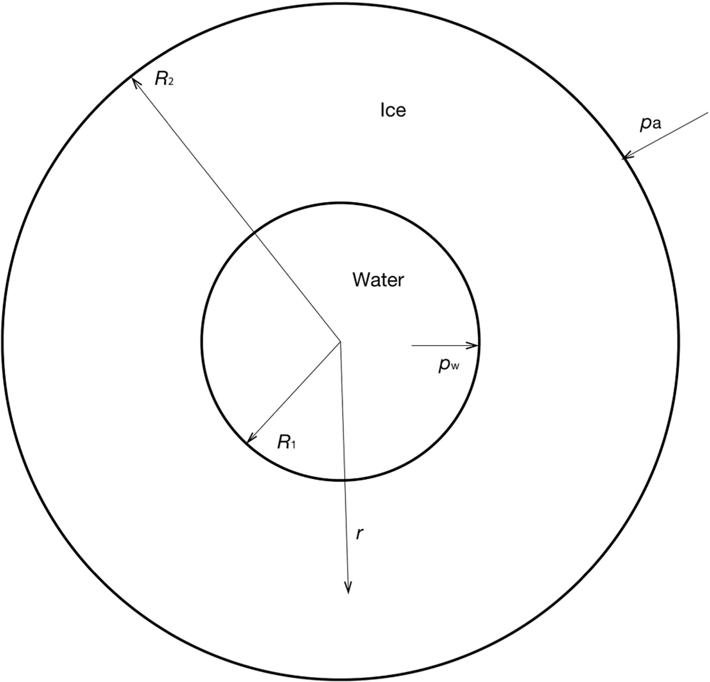
Fig. 1. A cross section of a cylindrical Röthlisberger channel, where the inner section is fully filled with water flowing out of the page, and the outer annulus is a finite-width ice layer.
where S is the channel cross-sectional area, m is the melt rate per unit length, ρ i is the ice density and v denotes the viscous closure of the tunnel. To specify the viscous closure term, work by Reference NyeNye (1953) was used. Nye showed that under the assumptions of radially symmetric and infinitely thick ice, the closure rate of the channel would be given by
where K is a constant, n is the Glen exponent for viscous ice (Reference GlenGlen, 1952) and N is the effective pressure within the channel. The effective pressure is defined as
where p w is the water pressure and p i is the overburden pressure of the ice, both evaluated at the ice/water interface. Coupling together these equations provides an equation that helps describe subglacial channel dynamics:
This equation has been widely used in the modelling of jökulhlaups. However it is typically only applied in the upstream region near the lake, as jökulhlaup models do not critically depend upon the dynamics of the tunnel exit (Reference FowlerFowler, 1999). As such, it is understandable that the following anomaly went unnoticed: at the terminus of the channel, x e, there is no overlying ice and thus the effective pressure is zero, which from Eqn (4) implies
This strictly positive rate of opening at the tunnel exit is physically impossible. To rectify the situation one might be tempted to modify m so that it also equals zero at x e. However its value will necessarily be positive in the limit of x → x e. Another possibility is that if a region of open channel flow towards the channel exists, the issue might be removed. In this case the effective pressure would be given by the ice pressure, and so
However, since pi must equal zero at the exit, there would be no creep closure and thus we would still have the issue of a strictly positive rate of channel widening. And so with no easy fixes to hand, we must return to the original modelling assumptions behind the closure law (Eqn (2)), to see how they can be improved in order to remove the issue of a forever-opening exit.
Ice Closure
We return to the model of Reference NyeNye (1953) for the creep closure of ice surrounding a cylindrical cavity of radius R 1, but this time I shall allow for a finite ice thickness to exist, of radius R 2. This geometry is highlighted in Figure 1, showing
which, upon differentiation with respect to time (represented by the raised dot), gives
This means that if I can solve for Ṙ 1 then I shall be able to find the viscous closure rate for the channel.
I make use of the Stokes slow-flow equations for viscous ice, which represent the conservation of ice momentum and mass, respectively:
Here p is the ice pressure, τ is the deviatoric stress tensor, g is gravity and u is the ice velocity. I retain Nye’s simplifying assumption of radially symmetric ice, centred on the middle of the channel, where the outer glacier field is simulated by treating gravity as falling radially inwards. In maintaining this assumption, the whole problem becomes radially symmetric, u = (u(r),0,0), where r is the radial distance from the midpoint of the channel. Converting Eqn (9) into polar coordinates allows me to write
With a simple integration (and using u(R 1) = Ṙ1) this second equation can be reduced to
In addition to the two slow-flow equations, I need a third equation to close the model. This is given by the generalized Glen flow law for viscous ice:
where A is an ice flow coefficient, τe is the effective stress defined as
and ![]() is the strain rate tensor, given by
is the strain rate tensor, given by
In cylindrical coordinates with radial symmetry (so ![]() ), Eqns (12) and (14) give the relations
), Eqns (12) and (14) give the relations
The above equations can then be added together and equalled to zero, via the incompressibility constraint (Eqn (102)), to provide
It then follows from Eqn (13) that
The explicit forms for τ and τrr can now be found by applying Eqns (11) and (17) to Eqn (15), to produce
and
With the form of the deviatoric shear stress now known, I apply it to the momentum equation in Eqn (10) in order to find the effective pressure, N, thereby linking it to the channel closure rate. At the boundaries of the ice (Fig. 1), force balances exist between the radial component of shear stress, σrr = − p + τrr, and the atmospheric and water pressures (p a and p w):
With these conditions, I integrate Eqn (101) between R1 and R2, and make use of the fact that pi = ρig(R 2 – R 1), to find
Here I have taken the atmospheric pressure to be negligible compared with the weight of the ice. By making substitutions from Eqns (19) and (8), I can integrate Eqn (21) to find our improved closure law for a cylindrical channel within ice:
where K = 2A/nn
and ![]() .
.
There is an obvious similarity between this modified closure law and that originally derived by Nye for infinitely thick ice, Eqn (2) (in the limit Sf → ∞ we regain Eqn (4)). Yet now we see a denominator term has appeared, where this denominator contains information regarding the overlying ice thickness. Crucially, it ensures that while S is growing, it is bounded above by Sf and the issue of a forever widening exit is removed. Further, since the denominator is <1, the closure rates of Röthlisberger channels are larger than previously thought.
Channel Evolution Equation
To be able to solve for the channel cross-sectional area (Eqn (1)) with our improved closure law (Eqn (22)), I first need to specify the melt rate per unit length, m, and the effective pressure, N. I shall make use of the melt rate function as used by Reference FowlerFowler (2009) and Reference EvattEvatt (2006) (its thermodynamic-based derivation is outside the scope of the current paper), the form of which can be taken as
Here Q is the water flux within the channel, L is the latent heat of melting and Ψ is the background hydraulic gradient, given by
where R0 is the height of the ice/bedrock interface (which is also the centre line of the channel).
In regard to the effective pressure, one can make use of the Manning flow law for turbulent water (as did Reference NyeNye, 1976) which can be rearranged to produce
where f is a constant and ρ w is the water density. The boundary condition for this equation is given by
With these equations I am able to write the evolution equation for S as
where N is given by Eqn (25). Once S is determined, one can find the channel radius, R 1, via Eqn (7).
Closed Channel Results
To compute R 1 I shall employ the indicative parameter values given in Table 1, where Q is prescribed, and assume that the ice surface and base are parallel to one another (thereby allowing easy replication of the results). Further, at the tunnel exit I simply prescribe S = Sf , as any smaller initial size will eventually reach this (steady-state) value. All results are found using an iterative root-finding scheme to find a steady value of S from Eqn (27) (i.e. where the time derivative is set to zero), while simultaneously using a simple finite-difference numerical scheme for Eqn (25).
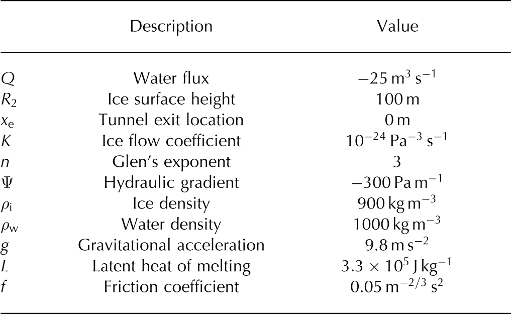
Table 1. Indicative parameter values
The first result, Figure 2, shows how the channel radius, R 1, matches the height of the ice at the tunnel exit. The bulk of the change in channel size is contained in the final 50 m before the channel exit. To see how this channel profile varies under a broad range of flux discharges, Figure 3 shows the profile for Q = 25, 250 and 2500m3 s−1 (corresponding to increasing S). We see the region in which the significant proportion of channel variation occurs is slowly pushed back to ~200m before the channel exit.
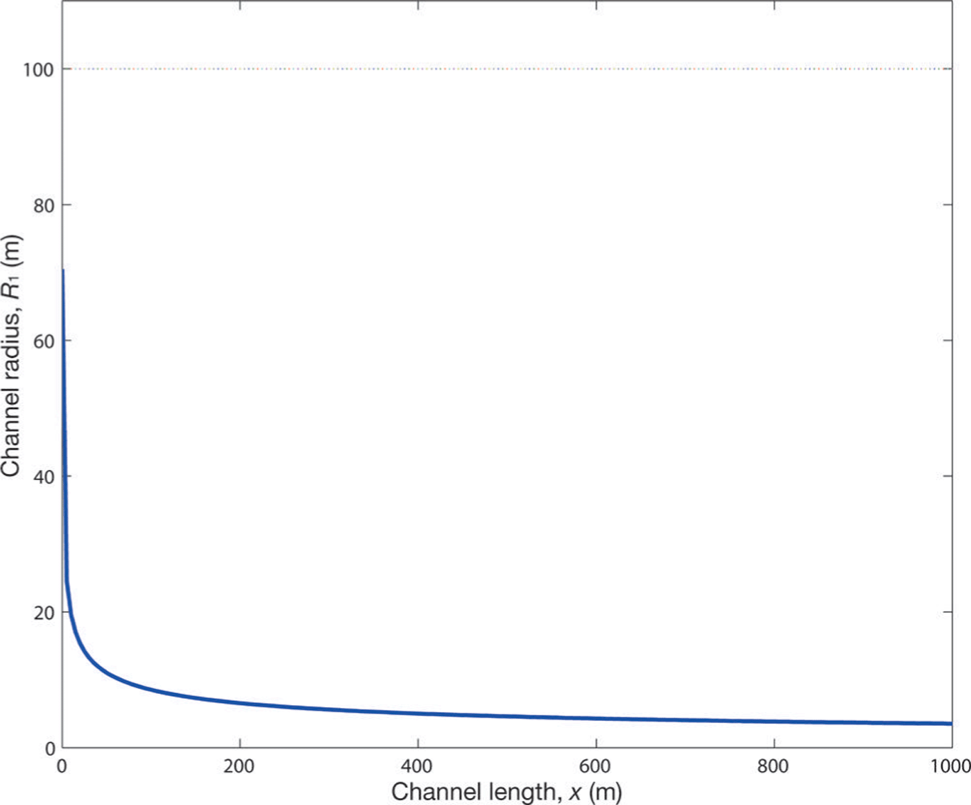
Fig. 2. A profile view of a Röthlisberger channel radius, inside an ice mass of 100 m elevation. This was solved using the improved closure law (Eqn (22)).
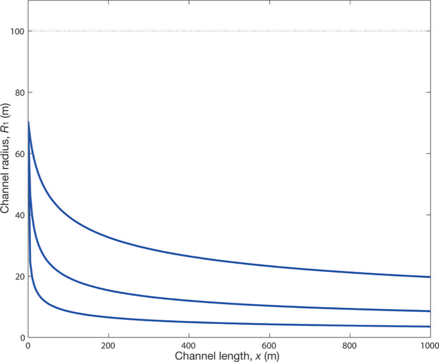
Fig. 3. A profile view of a Röthlisberger channel radius for three different discharge levels: for increasing S, Q = 25, 250 and 2500 m3 s−1.
To allow for a comparison between this paper’s bounded model and the original (unbounded) Röthlisberger model (Eqn (4)), Figure 4 plots a close-up view of the bounded channel radius (same as shown in Fig. 2) together with the far-upstream channel radius of the original Röthlisberger model. This far-upstream value is calculated from Eqn (25) with the limit ∂N/∂x → 0 as x → ∞ (Reference FowlerFowler, 1999), thereby ensuring this part of the original Röthlisberger channel is bounded; since it is bounded it serves as a suitable width for which to compare our improved model. As the result shows, the bounded model smoothly converges from above to this far-field value as one moves upstream. This is to be expected as the unbounded model implicitly assumes an infinite ice width and therefore its far-field value will have the narrowest channel radius.
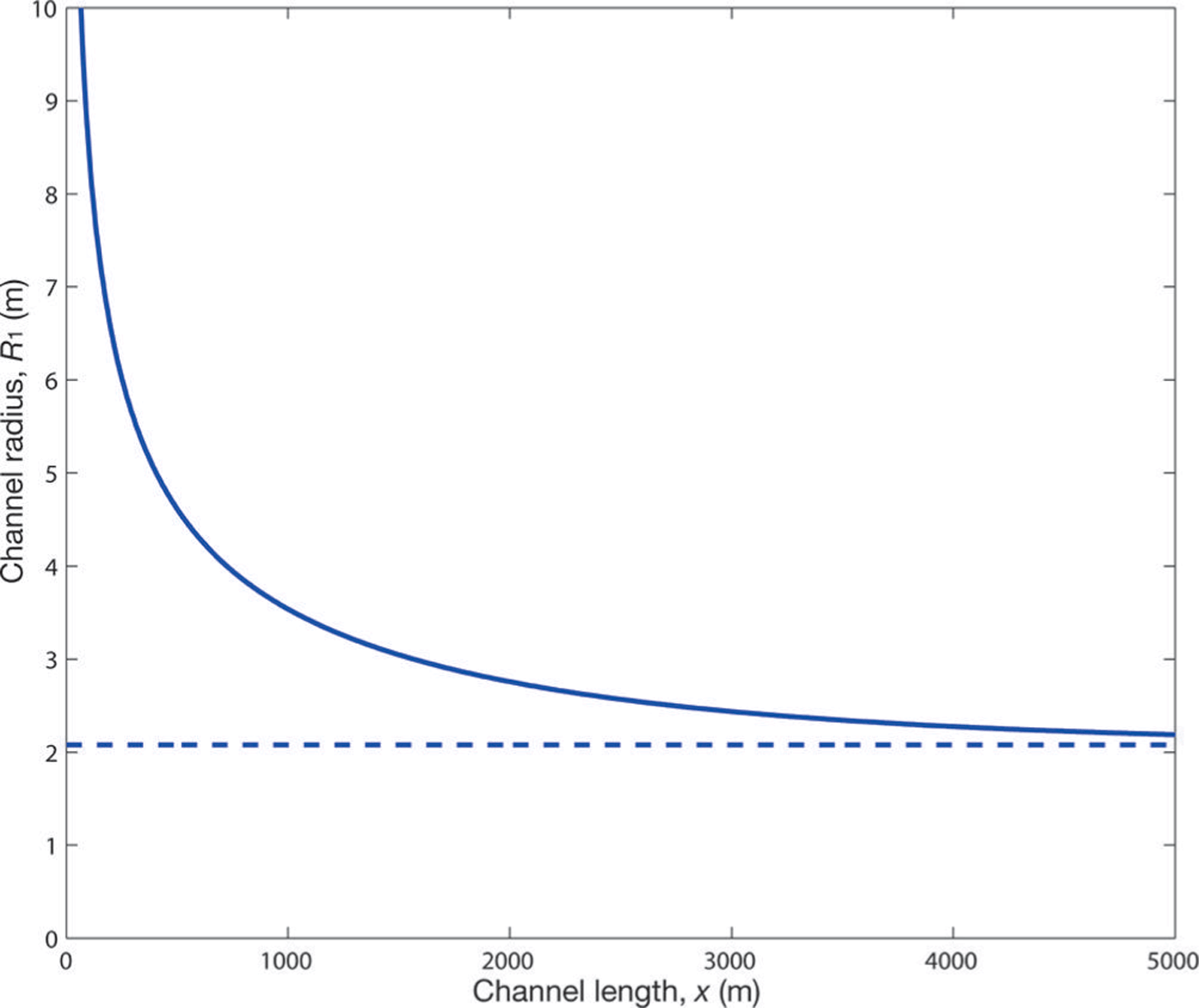
Fig. 4. A close-up profile view of a Röthlisberger channel radius (solid line), plotted against the far-upstream radius of a Röthlisberger channel without the modified closure law (dashed line).
Open Channel Flow
It appears that the issue of a forever-opening tunnel exit has been removed. Built within our modelling was an assumption that the tunnel will remain fully filled with water, right up to the tunnel exit. Yet this is contrary to the many observations of a region of the water, immediately upstream of the exit, being exposed to the atmosphere (Reference RöthlisbergerRöthlisberger, 1972). This situation is sketched in Figure 5. Although I showed why the open channel consideration would not have removed the forever-opening channel issue (see Eqn (6)), it is natural to see how this consideration will affect our modelling. In this section I calculate if, and where, a transition point from closed channel flow to open channel flow will occur.
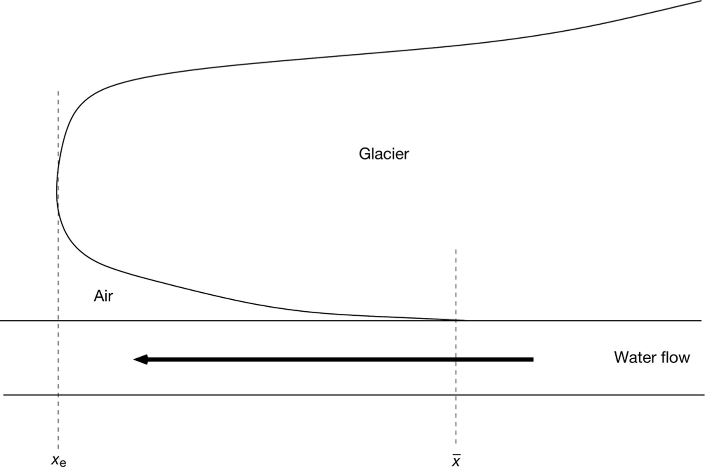
Fig. 5. A schematic profile image of a water channel flowing underneath a glacier, where the channel transitions from a region of closed channel flow to a region of open channel flow at x = ![]() .
.
We have seen the equations that govern N and S in the closed channel flow region are Eqns (25) and (27), respectively. These allow the derivation of the analogous equations for the open channel flow region to be conducted with ease. As previously mentioned, the effective pressure felt by the ice in the open channel region is the same as the overlying ice pressure, p i (with p w = p a negligible):
This open channel effective pressure can be placed into Eqns (3) and (24) to find the hydraulic potential is given by
which we see is defined solely by the topology of the bedrock. Substitution of this potential gradient into Eqn (23) provides the melt rate per unit length within the open channel,
Maintaining Röthlisberger’s principle of the channel’s dynamics being determined by a relationship between widening due to melt and viscous closure (Eqn (1)), I may write the open channel evolution equation as
With N and S within the open channel defined by Eqns (28) and (31), respectively, I can determine the transition point between closed and open channel flow, ![]() , via continuity arguments. Since the melt rate per unit length will be continuous throughout the channel (as are also S, Q, Φ and ∂N/∂x), it allows me to join up Eqns (25) and (28) to imply
, via continuity arguments. Since the melt rate per unit length will be continuous throughout the channel (as are also S, Q, Φ and ∂N/∂x), it allows me to join up Eqns (25) and (28) to imply
This extra condition (which links the closed and open channels) determines the location of ![]() . It is of note that this transition point can be applied to both steady and non-steady situations.
. It is of note that this transition point can be applied to both steady and non-steady situations.
I now calculate steady-state solutions for the transition point, which is achieved by solving for S(x) from the steady-state version of Eqn (31), and then seeing where its solution satisfies the transition criteria given by Eqn (32). I use the parameters of Table 1 and take the open channel hydraulic potential as
This prescription is for illustrative and replication purposes, and has been chosen so as to ensure a transition point exists (which is not the case if a constant value is used).
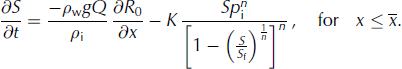
Figure 6 plots the transition point for different ice surface elevations, R
2. We see that for larger ice surface elevations, ![]() moves downstream along the tunnel in a monotonic fashion, similar to that predicted by Reference WeertmanWeertman (1972). For ice surface elevations above ~90 m, the entire channel is fully filled with water. To highlight the dependence of flux discharge upon the transition point, Figure 7 plots
moves downstream along the tunnel in a monotonic fashion, similar to that predicted by Reference WeertmanWeertman (1972). For ice surface elevations above ~90 m, the entire channel is fully filled with water. To highlight the dependence of flux discharge upon the transition point, Figure 7 plots ![]() against Q. We see the transition point moves upstream as the flux increases. This is because the closed channel’s (bounded) cross-sectional area widens for higher fluxes, thus reducing the weight of the overlying ice and allowing the evolution equation (Eqn (31)) (with its flattening bedrock topography, Eqn (33)) to be satisfied for a longer distance. The result reinforces the notion that during variable water discharges one should expect the transition point to vary (e.g. Reference Schuler and FischerSchuler and Fischer, 2009; Reference Hewitt, Schoof and WerderHewitt and others, 2012; Reference Kingslake and NgKingslake and Ng, 2013b).
against Q. We see the transition point moves upstream as the flux increases. This is because the closed channel’s (bounded) cross-sectional area widens for higher fluxes, thus reducing the weight of the overlying ice and allowing the evolution equation (Eqn (31)) (with its flattening bedrock topography, Eqn (33)) to be satisfied for a longer distance. The result reinforces the notion that during variable water discharges one should expect the transition point to vary (e.g. Reference Schuler and FischerSchuler and Fischer, 2009; Reference Hewitt, Schoof and WerderHewitt and others, 2012; Reference Kingslake and NgKingslake and Ng, 2013b).
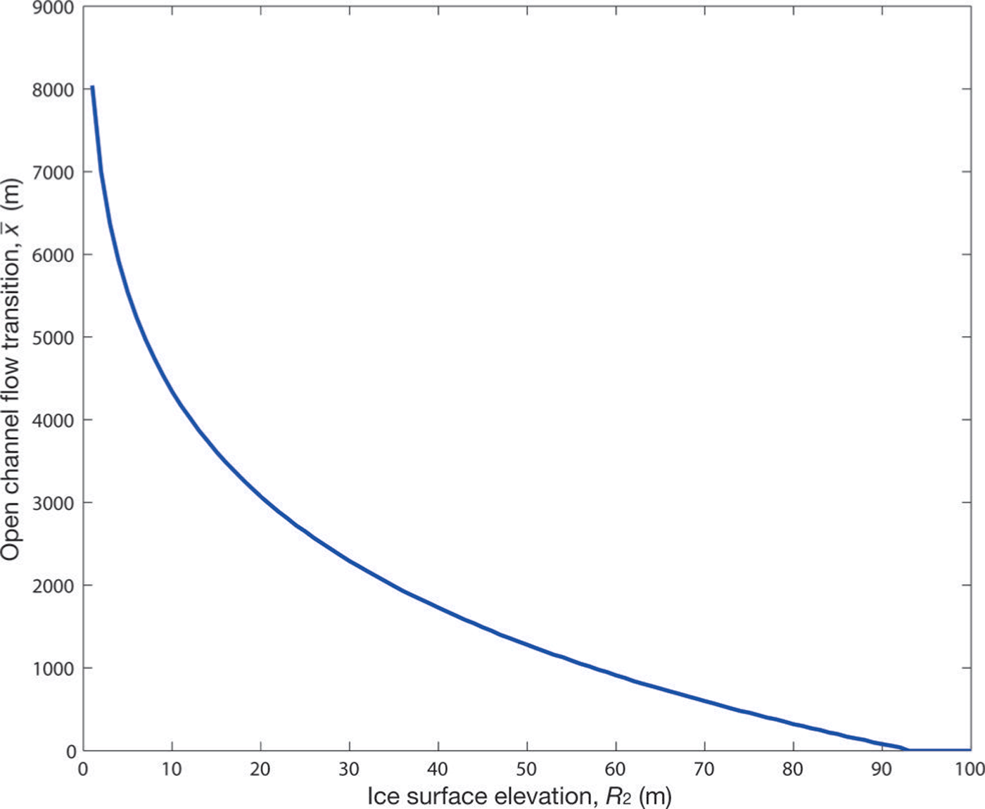
Fig. 6. The location of the transition point between closed and open channel flow, for different surface elevations.
Fig. 7. The location of the transition point between closed and open channel flow, for different flux discharges.
Discussion and Conclusions
This paper has shown how the issue of a forever-opening exit of a Röthlisberger channel can be removed by the consideration of a finite ice depth. In doing so it provides a link between channel behaviour and the overlying ice geometry. Fortunately, the resulting equation for channel evolution (Eqn (27)) does not add much additional complexity compared with the original (infinite ice depth) equation (Eqn (4)). I have also shown how one can incorporate a region of open channel flow into the modelling of Röthlisberger channels, thus allowing this common observation to be taken into account.
The behaviour of Röthlisberger channels is critically dependent upon the form of the ice closure law used. This paper continued the assumption of Reference RöthlisbergerRöthlisberger (1972) by taking the closure rate to be the same as that of cylindrical channels with gravity falling radially inwards. However this simplification will not always be suitable (Reference Hooke, Laumann and KohlerHooke and others, 1990), and thus criticisms of that are also applicable here (see Reference Benn and EvansBenn and Evans, 2010, for further discussion). Fortunately, the Röthlisberger model has had many successes (not least in providing a conceptual model of the underlying physical processes) and thus it is hoped that the improvements presented here will also help in this regard.
A natural next step for my investigation will be the derivation of a thermodynamic model for the melt rate per unit length within an open channel conduit. This is because the melt rate per unit length used here (Eqn (23)), and within the majority of jökulhlaup studies, has implicitly assumed temperature differences between the ice and the water to play a minor role (Reference EvattEvatt, 2006). A consequence of this temperature inclusion would be the open channel geometry no longer being cylindrical, due to non-uniform melting at the channel walls.
Acknowledgements
I am grateful to Andrew Fowler for the many conversations I had with him about this topic in the mid-2000s, and the financial support I received then from W.H.R. Evatt. I also thank Guðfinna Aðalgeirsdóttir, Alexander H. Jarosch and an anonymous referee for their their extremely helpful comments in reviewing this paper.


