
I. INTRODUCTION
Visual media such as photography, film, and Television were individual systems in the past. At present, they are digitized and can be treated on a common platform as pixel-based systems. These pixel-based systems are developing toward those with more pixels. This trend is exemplified by super high-definition TV (S-HDVT) [Reference Sugawara, Kanazawa, Mitani, Shimamoto, Yamashita and Okano1] or ultra-definition TV (UDTV). Although UDTV has more than 100 times the pixels of SDTV (standard-definition TV), the number of views is still single.
In the future, the demand for more pixels will be saturated, and more views will be needed. This is the direction for 3DTV and free-viewpoint television (FTV) [Reference Tanimoto2–Reference Tanimoto, Tehrani, Fujii and Yendo15]. It will result in the evolution from pixel-based systems to ray-based systems. FTV has been developed according to this scenario.
FTV is an innovative visual media that enables users to view a 3D scene by freely changing their viewpoints as if they were there. We proposed the concept of FTV and verified its feasibility with the world's first real-time system including the complete chain of operation from image capture to display as shown in Fig. 1 [Reference Sekitoh, Fujii, Kimoto and Tanimoto16].

Fig. 1. The world's first FTV (bird's-eye view system).
2DTV delivers a single view and 3DTV delivers two or more views. On the other hand, FTV delivers infinite number of views since the viewpoint can be placed anywhere. Therefore, FTV is regarded as the ultimate 3DTV. Furthermore, FTV could be the best interface between humans and environment and an innovative tool to create new types of content and art.
FTV enables realistic viewing and free navigation of three-dimensional (3D) scenes. Thus, FTV became the key concept of the 2022 FIFA World Cup bidding by Japan though the bid was not successful. Japan planned to deliver a 3D replica of soccer stadiums all over the world by FTV. This plan was presented in the bid concept video “Revolutionising Football.”
All ray information of a 3D space has to be transmitted to the receiver side to realize FTV. This is very challenging and needs new technologies. FTV was realized based on the ray-space method [Reference Fujii17–Reference Tanimoto, Nakanishi, Fujii and Kimoto20]. Ray technologies such as ray capture, processing, and display have been developed for FTV. An all-around ray-reproducing 3DTV [Reference Yendo, Fujii, Tehrani and Tanimoto21] was also realized by using these technologies.
FTV was proposed to MPEG [Reference Tanimoto and Fujii22]. MPEG started two standardization activities of FTV. One is multiview video coding (MVC) [23]. MVC is the first phase of FTV. It started in 2004 and ended in 2009. Another is 3D Video (3DV) [24]. 3DV is the second phase of FTV. It started in 2007 and “Call for Proposals on 3D Video Coding Technology” was issued in 2011 [25]. 3DV is still in progress.
In this paper, the FTV system and its technologies are reviewed. The international standardization of FTV is also described.
II. PROGRESS OF 3D CAPTURE AND DISPLAY CAPABILITIES
The development of television has two directions, UDTV direction and 3DTV/FTV direction. Figure 2 categorizes various types of television in a pixel-view domain. Although 3DTV/FTV and UDTV have different directions, there is similarity in technologies. For example, an integral photography system with many elemental lenses uses a UDTV camera for capture [Reference Arai26]. Roughly speaking, SD-FTV can be achieved with the technology of HDTV, and HD-FTV achieved with that of UDTV, by assigning some of the pixels in HDTV and UDTV to views.

Fig. 2. Categorization of television.
The pixel-view product (PV product) is defined as a measure to express the ability of visual media in two directions commonly. The PV product is defined as the “number of pixels” times “number of views” and can express 3D capture and display capabilities.
Figure 3 shows the progress of the PV product for various types of 3D capture and display. All data of the PV product in this figure have the frame rate of 30 or 25 fps except “multicamera (300 views)” that consists of still cameras. Here, the progress of space-multiplexing displays follows Moore's law because it is achieved by miniaturization. The PV product of the time-multiplexing display is roughly 10 times larger than that of space-multiplexing display. This factor is achieved by time-multiplexing technology. The progress of capture may not follow Moore's law because it depends on camera resolution and the number of cameras used.

Fig. 3. Progress of 3D capture and display capabilities.
It is seen that the PV product has been increasing rapidly year after year in both capture and display. This rapid progress indicates that not only two-view stereoscopic 3D but also advanced multiview 3D technologies are maturing. This development strongly supports introduction of 3DTV and FTV.
III. SCENE REPRESENTATION FOR FTV
A) Principle of FTV
FTV uses multicamera to capture views. However, displayed views are not captured views but generated views. The virtual viewpoint of FTV can be set anywhere.
A group of rays crossing the center of the lens of the virtual camera are needed to generate a free-viewpoint image as shown in Fig. 4. Some of these rays are captured by real cameras. However, there are many rays that are not captured by any cameras. These missing rays need to be generated by ray interpolation. Thus, the free-viewpoint image generation of FTV is made by ray integration and interpolation. This process is carried out systematically in ray-space as described in the next section.

Fig. 4. Rays necessary for free viewpoint image generation.
“A group of rays passing through one point” is an important concept. It is used in two cases as shown in Fig. 5. One is view capture by a real camera and view generation by a virtual camera. Another is ray-interpolation. It is used for ray interpolation so that one point on the diffusing surface of the object emits rays with equal magnitude.

Fig. 5. Concept of “a group of rays passing through one point” is used in two cases.
B) Ray-space representation
FTV was developed based on ray-space representation [Reference Fujii17–Reference Tanimoto, Nakanishi, Fujii and Kimoto20]. In ray-space representation, one ray in 3D real space is represented by one point in ray-space. Ray space is a virtual space. However, it is directly connected to real space. Ray space is generated easily by collecting multiview images while giving consideration to the camera parameters.
Let (x, y, z) be three space coordinates and (θ, φ) be the parameters of direction. A ray going through space an be uniquely parameterized by its location (x, y, z) and its direction (θ, φ); in other words, a ray can be mapped to a point in this 5D, ray-parameter space. In this ray-parameter space, we introduce the function f, whose value corresponds to the intensity of a specified ray. Thus, all the intensity data of rays can be expressed by
This ray-parameter space is the “ray-space.” It is clear that ray-space is 6D if time is included as a parameter.
Although the 5D ray-space mentioned above includes all information viewed from any viewpoint, it is highly redundant due to the straight traveling paths of the rays. Thus, when we treat rays that arrive at a reference plane, we can reduce the dimension of the parameter space to 4D.
Two types of ray-space are used for FTV. One is orthogonal ray-space, where a ray is expressed by the intersection of the ray and the reference plane and the ray's direction as shown in Fig. 6. Another is spherical ray-space, where the reference plane is set to be normal to the ray as shown in Fig. 7. Orthogonal ray-space is used for parallel view and spherical ray-space is used for convergent view.

Fig. 6. Definition of orthogonal ray-space.

Fig. 7. Definition of spherical ray-space.
Although the 4D ray-space gives both horizontal parallax and vertical parallax, the horizontal parallax is more important than the vertical parallax. If the vertical parallax is neglected, ray-space becomes 3D with parameters x, y, θ. The 3D ray-space is explained further in the following.
Two types of camera arrangements, linear and circular arrangements, are shown in Fig. 8. The linear camera arrangement is used to obtain 3D orthogonal ray-space and the circular arrangement is used to obtain 3D spherical ray-space.

Fig. 8. Two types of camera arrangements for 3D ray-space.
From the linear camera arrangement, orthogonal ray-space is constructed by placing many camera images upright and parallel, as shown in Fig. 9. However, this ray-space has vacancies between camera images when camera setting is not dense enough.

Fig. 9. Acquisition of orthogonal ray-space by multicamera.
The relation between real space and ray-space is shown in Fig. 10. A group of rays crossing a point in real space forms a straight line for a fixed y (a plane for various y) in ray-space. Therefore, if P is a point on the surface of an object, the line has the same magnitude because rays emitted from P have the same magnitude. It means that the horizontal cross section of ray-space has a line structure. This line structure of the ray-space is used for ray-space interpolation and compression.

Fig. 10. Relation between real-space and ray-space.
Figure 11 shows multiview images and ray-space interpolation. Although there are vacancies between images, it is seen that the horizontal cross section has a line structure. Ray-space interpolation is needed to obtain dense ray-space. It is done by detecting the slope of lines and then interpolating multiview images along the detected line. The slope of the line corresponds to the depth of the object. A typical example of interpolated orthogonal ray-space with a horizontal cross section is shown in Fig. 12.

Fig. 11. Multiview images and ray-space interpolation.

Fig. 12. Typical example of orthogonal ray-space and a horizontal cross section.
At present, dense camera setting is needed to handle non-Lambertian cases because Lambertian reflection is assumed for ray interpolation. Ray interpolation in non-Lambertian cases is an issue to be solved.
Once the ray-space is obtained, a free-viewpoint image is generated by cutting the ray-space vertically with a plane. Vertical cross sections of the ray-space give view images at the corresponding viewpoints as shown in Fig. 13. The relation between the movement of viewpoint and the shift of plane in ray-space is shown in Fig. 14.

Fig. 13. Generation of view images.

Fig. 14. Relation between the movement of viewpoint and the shift of plane in ray-space.
From the circular camera arrangement, spherical ray-space is constructed by placing many camera images upright and parallel as orthogonal ray-space. However, its horizontal cross section has a sinusoidal structure as shown in Fig. 15. The sinusoidal structure of spherical ray-space is also used for ray-space interpolation and compression.

Fig. 15. Example of spherical ray-space.
There are other ray representations such as light field rendering [Reference Levoy and Hanrahan27] and concentric mosaic [Reference Shum and He28]. However, light field is the same as orthogonal ray-space and concentric mosaic is the same as spherical ray-space.
IV. FTV SYSTEM
A) Configuration of FTV system
Figure 16 shows the configuration of the FTV system. At the sender side, a 3D scene is captured by multiple cameras. The captured images contain the misalignment and luminance differences of the cameras. They must be corrected to construct ray-space. The corrected images are compressed for transmission and storage by the MVC encoder.

Fig. 16. Configuration of FTV system.
At the receiver side, reconstructed images are obtained by the MVC decoder. The ray-space is constructed by arranging the reconstructed images and interpolating them. Free-viewpoint images are generated by cutting the ray-space vertically and are displayed on a 2D/3D display.
The function of FTV was successfully demonstrated by generating photo-realistic, free-viewpoint images of the moving scene in real time. Each part of the process shown in Fig. 16 is explained in greater detail below.
B) Capture
A 1D-arc capturing system shown in Fig. 17 was constructed for a real-time FTV system covering the complete chain of operation from video capture to display [Reference Na Bangchang, Fujii and Tanimoto29,Reference Na Bangchang, Tehrani, Fujii and Tanimoto30]. It consists of 16 cameras, 16 clients, and 1 server. Each client has one camera and all clients are connected to the server with Gigabit Ethernet.

Fig. 17. 1D-arc capturing system.
A “100-camera system” was developed to capture larger space [Reference Fujii, Mori, Takeda, Mase, Tanimoto and Suenaga31]. The system consists of one host–server PC and 100 client PCs (called ‘nodes’) that are equipped with JAI PULNiX TM-1400CL cameras. The interface between camera and PC is called Camera-Link. The host PC generates a synchronization signal and distributes it to all of the nodes. This system is capable of capturing not only high-resolution video with 30 fps but also analog signals of up to 96 kHz. The specification of the 100-camera system is listed in Table 1.
Table 1. Specification of 100-camera system.

The camera setting is flexible as shown in Fig. 18. We captured test sequences shown in Fig. 19 and provided them to MPEG. They are also available for academic purposes.

Fig. 18. 100-camera system.

Fig. 19. MPEG test sequences.
The 100-camera system can capture 3D scenes in a space the size of a classroom. Capture for a very large space such as a soccer stadium is still difficult.
C) Correction
The geometric correction [Reference Matsumoto, Yendo, Fujii and Tanimoto32,Reference Fukushima, Yendo, Fujii and Tanimoto33] and color correction [Reference Yamamoto, Yendo, Fujii and Tanimoto34] of multicamera images are performed by measuring the correspondence points of images. This measurement is made once the cameras are set.
An example of geometric correction is shown in Fig. 20. Here, the geometric distortion of a 1D camera array is corrected. It is seen that the positions and directions of multiple cameras are aligned after geometric correction. An example of color correction is shown in Fig. 21.

Fig. 20. Positions and directions of multiple cameras before and after geometric correction.

Fig. 21. An example of color correction.
References [Reference Zhang35–Reference Sonka, Hlavac and Boyle39] give more information on geometric correction.
D) MVC encoding and decoding
An example of time and view variations of multiview images is shown in Fig. 22. They have high temporal and interview correlations. MVC reduces these correlations [23,Reference He, Ostermann, Tanimoto and Smolic40,Reference Yamamoto41]. The standardization of multicamera image compression is progressing with MVC in MPEG. The details are described in Section V.

Fig. 22. Time and view variations of multiview images.
E) View generation
Ray-space is formed by placing the reconstructed images vertically and interpolating them. Free-viewpoint images are generated by making a cross section of ray-space.
Examples of the generated free-viewpoint images are shown in Fig. 23. Complicated natural scenes, including sophisticated objects such as small moving fish, bubbles, and reflections of light from aquarium glass, are reproduced very well.

Fig. 23. An example of generated FTV images at various times and viewpoints.
The quality of the generated view images depends on ray-space interpolation methods. Ray-space interpolation is achieved by detecting depth information pixel by pixel from the multiview video. Several interpolation methods of ray-space have been proposed [Reference Nakanishi, Fujii, Kimoto and Tanimoto42–Reference Fukushima, Yendo, Fujii and Tanimoto45]. Global optimization techniques [Reference Szeliski46] such as Dynamic Programming [Reference Fukushima, Yendo, Fujii and Tanimoto45,Reference Criminisi, Blake, Rother, Shotton and Torr47], Belief Propagation [Reference Sun, Li, Bing Kang and Shum48,Reference Yang, Wang, Yang, Stewenius and Nister49], and Graph Cuts [Reference Kolmogorov and Zabih50–Reference Deng, Yang, Lin and Tang54] give better depth estimation. However, they take more time for computation.
Dependence of peak signal-to-noise ratio (PSNR) of interpolated images on maximum disparity for various interpolation methods is shown in Fig. 24. The PSNR decreases in accordance with the increase of maximum disparity for any interpolation method. However, the magnitude of PSNR strongly depends on the interpolation method. Therefore, the development of interpolation methods with higher performance is very effective to increase camera interval and hence to decrease the number of cameras.

Fig. 24. Dependence of PSNR of interpolated images on maximum disparity.
The free-viewpoint images were generated by a PC cluster in [Reference Na Bangchang, Fujii and Tanimoto29]. Now, they can be generated in real time by a single PC [Reference Fukushima, Yendo, Fujii and Tanimoto44] or a mobile player as shown in Fig. 25 due to the rapid progress of the computational power of processors.

Fig. 25. FTV on a laptop PC and a mobile player.
The free viewpoint can move forward and backward. However, the resolution of generated view is decreased when it moves forward. This is because the rays captured by cameras become sparse at the forward position.
F) Display
FTV needs a new user interface to display free-viewpoint images. As shown in Fig. 26, two types of display, 3D display and 2D/3D display with a viewpoint controller, were developed for FTV.

Fig. 26. Two types of display for FTV.
Viewpoint control by head-tracking is shown here. Many head-tracking systems have been proposed using magnetic sensors, various optical markers, infrared cameras, retroreflective light from retinas, etc. However, a head-tracking system developed here uses only a conventional 2D camera and detects the position of a user's head by image processing. The user does not need to attach any markers or sensors.
In the user interface using a 2D display, the location of the user's head is detected with the head-tracking system and the corresponding view image is generated. Then, it is displayed on the 2D display as shown in Fig. 27.

Fig. 27. 2D display with head tracking.
In the user interface using autostereoscopic display, the function of providing motion parallax is extended by using the head-tracking system. The images fed to the system change according to the movement of the head position to provide small motion parallax, and the view channel for feeding the images is switched for handling large motion. This means that binocular parallax for the eyes is provided by autostereoscopic display, while motion parallax is provided by head tracking and changing the image adaptively as shown in Fig. 28.
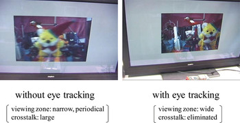
Fig. 28. 3D display with and without head tracking.
V. RAY TECHNOLOGIES
A) Ray acquisition
Ray capturing systems [Reference Fujii and Tanimoto55–Reference Fujii, Yendo and Tanimoto57] that acquire a dense ray-space without interpolation in real time were developed. In these capturing systems, a high-speed camera and a scanning optical system are used instead of multiple cameras. The important feature of this configuration is that the spatial density of multicamera setup is converted to temporal density, i.e. the frame rate of the camera. Therefore, dense multicamera setup can be realized equivalently by increasing the frame rate of the camera.
An all-around ray acquisition system of this configuration is shown in Fig. 29. This system uses two parabolic mirrors. All incident rays that are parallel to the axis of a parabolic mirror gather at its focus. Hence, rays that come out of an object placed at the focus of the upper parabolic mirror gather at the focus of the lower parabolic mirror and generate the real image of the object. A rotating aslope mirror scans these rays and the image from the aslope mirror is captured by a high-speed camera. All-around dense convergent views of an object are captured by using this system.

Fig. 29. All-around dense ray acquisition system.
B) Ray display
Figure 30 shows the SeeLINDER [Reference Yendo, Fujii, Tanimoto and Pahpour Tehrani58], a 360°, ray-reproducing display that allows multiple viewers to see 3D FTV images. The ray-reproducing display needs not only magnitude control but also direction control of rays. Figure 31 shows the mechanism of magnitude and direction control of rays in the SeeLinder.

Fig. 30. The SeeLINDER, a 360°, ray-reproducing display.

Fig. 31. Mechanism of magnitude and direction controls of rays.
The SeeLinder consists of a cylindrical parallax barrier and 1D light-source arrays. Semiconductor light sources such as LEDs are aligned vertically for the 1D light-source arrays. The cylindrical parallax barrier rotates quickly, and the light-source arrays rotate slowly in the opposite direction. If the aperture width of the parallax barrier is sufficiently small, the light going through the aperture becomes a thin flux, and its direction is scanned by the movement of the parallax barrier and the light-source arrays. By synchronously changing the intensity of the light sources with scanning, pixels whose luminance differs for each viewing direction can be displayed. The displayed images have strong depth cues of binocular disparity and natural 3D images can be seen. As we move around the display, the image changes according to their viewing positions. Therefore, we perceive the displayed objects as floating in the cylinder.
C) All-around ray-reproducing 3DTV
An all-around ray-reproducing 3DTV was constructed [Reference Yendo, Fujii, Tehrani and Tanimoto21]. It captures and displays 3D images covering 360° viewing zone horizontally in real time. As shown in Fig. 32, this system consists of a mirror-can ray capturing unit, a real-time distortion correction and data conversion unit, data-transferring system, and a cylinder-shaped all-around 3D display. The capturing unit acquires multi-view images from all horizontal directions around an object with narrow view interval to obtain dense rays. The distortion correction and data conversion unit performs real-time correction of rotation and distortion caused by optics of the ray capturing unit, and conversion from captured data to displayed data.
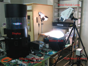
Fig. 32. All-around ray-reproducing 3DTV.
D) Ray processing
The ray-space is a platform of ray processing. Various kinds of signal processing can be completed in ray-space. Vertical cross sections of ray-space give real view images at the corresponding viewpoints. Manipulation, division, and composition of 3D scenes are also performed by ray-space processing.
Figure 33 shows an example of ray-space processing. Bars in the scene of Fig. 33(a) are eliminated in Fig. 33(b) by applying non-linear filtering to ray-space [Reference Takano, Yendo, Fujii and Tanimoto59].
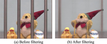
Fig. 33. An example of ray-space processing: object elimination by non-linear filtering.
Composition of 2 scenes shown in Fig. 34 is performed by ray-space processing as shown in Fig. 35 [Reference Takano, Yendo, Fujii and Tanimoto60].

Fig. 34. Scene composition by ray-space processing.

Fig. 35. Ray-space processing for scene composition.
Images with optical effects such as multiple reflection and mirage are generated by cutting ray-space with a curved plane as shown in Fig. 36. The shape of the curved plane is determined due to an optical effect to be realized. Artistic images shown in Fig. 37 are generated by cutting ray-space with more general planes [Reference Chimura, Yendo, Fujii and Tanimoto61,Reference Chimura, Yendo, Fujii and Tanimoto62].

Fig. 36. Cutting ray-space with curved planes for image generation with optical effects.

Fig. 37. Examples of artistic images generated by cutting the ray-space with more general planes.
VI. INTERNATIONAL STANDARDIZATION OF FTV
FTV was proposed to MPEG in December 2001. Figure 38 shows the history of FTV standardization at MPEG.

Fig. 38. History of FTV Standardization in MPEG.
In the 3D Audio Visual (3DAV) group of MPEG, many 3D topics such as omni-directional video, FTV, stereoscopic video, and 3DTV with depth disparity information were discussed. According to the comments of the industry, the discussion converged on FTV in January 2004.
Then, the standardization of the coding part of FTV started as MVC. The MVC activity moved to the Joint Video Team (JVT) of MPEG and ITU for further standardization processes in July 2006. The standardization of MVC is based on H.264/MPEG4-AVC and was completed in March 2009 [Reference Vetro, Wiegand and Sullivan63]. MVC was the first phase of FTV. MVC has been adopted by Blu-ray 3D.
FTV cannot be constructed by coding part alone. Standardization of entire FTV was proposed [Reference Tanimoto, Fujii, Kimata and Sakazawa64] and MPEG started a new standardization activity of FTV in April 2007.
In January 2008, MPEG-FTV targeted the standardization of 3DV. 3DV is the second phase of FTV and a standard that targets serving for a variety of 3D displays [65].
Frameworks of MVC and 3DV are shown in Figs 39 and 40, respectively. In MVC, the number of input views and output views are the same. On the other hand, in 3DV, the number of output views is larger than that of input views, where the view synthesis function of FTV is used to increase the number of views.

Fig. 39. Framework of MVC.

Fig. 40. Framework of 3DV.
The function of view generation in Fig. 16 is divided into depth search and interpolation. As shown in Fig. 41, an FTV system can be constructed in various ways, depending on the location of depth search and interpolation. In case A, both depth search and interpolation are performed at the receiver side as in Fig. 15. In case B, depth search is performed at the sender side and interpolation is performed using depth information [Reference Fehn66,Reference Mori, Fukushima, Yendo, Fujii and Tanimoto67] at the receiver side. In case C, both depth search and interpolation are performed at the sender side. Case B is suitable for download/package and broadcast services since processing at the sender side is heavy and processing at the receiver side is light.

Fig. 41. Three cases of FTV configuration based on the positions of depth search and interpolation.
The data formats of the three cases in Fig. 41 are shown in Fig. 42 for comparison. They are the horizontal cross sections of data. As explained in Fig. 11, ray-space interpolation from multiview images is done by detecting the slope of lines. The slope of lines corresponds to the depth as shown in (b) of Fig. 42. Therefore, ray-space can be obtained easily from the multiview + depth data of case B.

Fig. 42. Relationship among FTV data formats.
Case B was adopted by the FTV reference model [68] as shown in Fig. 43. At the sender side of the FTV reference model, multiview images are captured by multiple cameras. The captured images contain the misalignment and color differences of the cameras. They are corrected and the depth of each camera image is obtained by using Depth Estimation Reference Software (DERS) [Reference Tanimoto, Fujii, Suzuki, Fukushima and Mori69]. The multiview + depth data are compressed for transmission and storage by the encoder. At the receiver side, the multiview + depth data are reconstructed by the decoder. Free-viewpoint images are synthesized using multiview + depth information and displayed on a 2D/3D display. The synthesis is carried out by using View Synthesis Reference Software (VSRS) [Reference Tanimoto, Fujii, Suzuki, Fukushima and Mori69].

Fig. 43. FTV reference model.
Thus, FTV is a new framework that includes a coded representation for multiview video and depth information to support the generation of high-quality intermediate views at the receiver. This enables free viewpoint functionality and view generation for 2D/3D displays.
A semi-automatic mode of depth estimation was developed to obtain more accurate depth and clear object boundaries [Reference Wildeboer, Fukushima, Yendo, Tehrani, Fujii and Tanimoto70]. In this mode, manually created supplementary data are input to help automatic depth estimation. View synthesis using depth information is sensitive to the error of depth. It can be reduced by a reliability check of depth information due to multiview plus depth data [Reference Yang, Yendo, Tehrani, Fujii and Tanimoto71,Reference Yang, Yendo, Tehrani, Fujii and Tanimoto72]. This method is also effective to reduce the error of depth coding [Reference Yang, Wildeboer, Yendo, Tehrani, Fujii and Tanimoto73].
“Call for Proposals on 3D Video Coding Technology” was issued in March 2011 [24]. The framework of Call for Proposals on 3D Video Coding Technology is shown in Fig. 44. In total 23 proposals from 20 organizations were received. The proposals were evaluated in November 2011. Standardization will be made on the following three tracks in 2 years [74].
(1) MVC compatible extension including depth
No block-level changes, only high-level syntax is changed.
(2) AVC compatible video-plus-depth extension
30–40% improvement relative to AVC/MVC is expected.
(3) High Efficiency Video Coding (HEVC) 3D extensions
40–60% improvement relative to HEVC is expected.

Fig. 44. Framework of Call for Proposals on 3D Video Coding technology.
VII. CONCLUSION
FTV is the ultimate 3DTV with infinite number of views and ranked at the top of visual media. FTV enables realistic viewing and free navigation of 3D scenes as planned for the FIFA World Cup. FTV is not a conventional pixel-based system but a ray-based system. FTV has been realized by developing ray capture, display, and processing technologies.
However, there remain many issues for FTV. For example, FTV for a large-scale 3D space such as a soccer stadium and walk-through type FTV have not yet been realized. As for individual technologies, ray capture by multicamera is still not easy. Reduction of the number of cameras is very desirable. Direct ray capture without interpolation for a large 3D space is another challenging issue. As for transmission, current MPEG 3D standardization treats multiview less than 32 views. Thus, “super multiview video coding” for multiview larger than 32 views and “ray-space coding” will be the next targets. Specular reflection and the decrease of resolution at the forward position are important issues in view synthesis. In addition, free listening-point audio has to be implemented in synchronization with free viewpoint video for FTV.
FTV will find many applications in various fields of society such as broadcast, communication, sports, amusement, entertainment, advertising, design, exhibition, education, medicine, and so on. Rapid progress of capture, display, and processing technologies will accelerate the introduction of FTV.
ACKNOWLEDGEMENTS
This research was partially supported by the Strategic Information and Communications R&D Promotion Programme (SCOPE) of the Ministry of Internal Affairs and Communications, National Institute of Information and Communications Technology, Japan (NICT), and Grant-in-Aid for Scientific Research (B), 22360151.


 Open access