


Severe hip flexor muscle spasticity can occur in upper motor neuron syndrome of multiple etiologies. It can be associated with cerebral palsy (CP), multiple sclerosis, spinal cord injuries, severe traumatic brain injuries, and late Parkinson’s disease with dementia and paratonia. In elderly bed confined patients, flexed hip position can cause serious skin complications and is a barrier to perineal care. Reference Jog, Wein and Bhogal1 Focal spasticity can be controlled well with botulinum neurotoxin (BoNT) injections, improving quality of life. Reference Jog, Wein and Bhogal1–Reference Westhoff, Seller, Wild, Jaeger and Krauspe5 In cases of hip flexor spasticity in CP children, the common approach is to inject BoNT targeting “iliopsoas” muscle through the femoral (Scarpa’s) triangle. Reference Westhoff, Seller, Wild, Jaeger and Krauspe5–Reference Willenborg, Shilt, Smith, Estrada, Castle and Koman7 However, using this femoral triangle approach, mostly the iliacus (ILC) is injected, as the psoas major (PM) is largely tendinous in this area. In order to optimize clinical outcomes, it has been reported that BoNT injection should be close to the motor end plate (MEP) zone of a muscle. Reference Gracies, Lugassy, Weisz, Vecchio, Flanagan and Simpson8 The MEP zone of PM has been found to be located proximally in the muscle belly, Reference Van Campenhout and Molenaers9,Reference Van Campenhout, Verhaegen, Pans and Molenaers10 which can be accessed better through a posterior lumbar approach. The posterior lumbar approach has been described in the literature Reference Farny, Girard and Drolet11–Reference Koyama, Murakami, Suzuki and Suzaki13 ; however, it has not been incorporated into clinical practice due to a perceived risk of injury to the kidney, abdominal aorta (AA), and inferior vena cava (IVC). The L4–L5 transverse processes (TP) can be used as a landmark for ultrasound (US)-guided BoNT injection, as PM lies directly anterior to the TPs. The feasibility of using an US-guided posterior lumbar approach has not been assessed. The purpose of this cadaveric study was to investigate the feasibility and accuracy of US-guided PM injection using a posterior lumbar approach to assess the intra- and extramuscular spread of injectate in the surrounding structures.
Methods
Eight lightly embalmed cadavers with mean age 81.6 ± 10.2 (4M/4F) were used in this study. Cadavers had no visible signs of musculoskeletal pathology or previous surgery. Ethics approval was received from the University of Toronto Health Sciences Research Ethics Board (27210). For sonographic guidance of injections, a LOGIQ™ e (General Electric Healthcare, Chicago, IL, USA) real-time US scanner with a GE C1-5-RS (Convex) curved array probe was used. This probe was chosen for better resolution up to a depth of 8–12 cm. Imaging was optimal at a frequency of 4 MHz using B beam with contrast harmonic imaging (chi).
The specimens were placed in a semi-prone position supported by blocks to prevent movement during the procedure. To localize the site of injection, the following were identified and demarcated using a skin marker: midline (interspinous line), iliac crest (IC), and lateral border of erector spinae (ES) (Figure 1). The PM injection site was located in the angle between the posterior IC and the lateral border of ES, corresponding to vertebral level L4–L5 (Figure 1A). Prior to injection, using US scanning, the IC, TP of L4 and L5 vertebrae, and the inferior pole of the kidney were identified (Figure 1B).
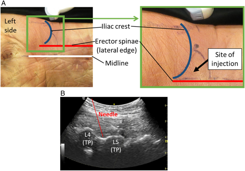
Figure 1: Landmarking and site of injection. (A) Specimen with landmarking. Inset shows enlargement of site of injection. (B) Ultrasound scan showing needle position. L, lumbar vertebra; TP, transverse process.
PM injections were carried out using a 3″ cannulated, 27 gauge needle attached to a 3-ml syringe by the second author (S.S.), a physiatrist who has more than 27 years of experience in spasticity management and 3 years of experience using US guidance, and has been using electromyography (EMG) and US-guided injections in PM. The injectate consisted of 2 ml of saline mixed with toluidine blue, the volume commonly used in clinical practice (100 units of onabotulinumtoxinA using 2:1 dilution). In most specimens, the PM was reached at about a depth of 2″ (50 mm). The cadavers were lightly embalmed, but due to prolonged supine positioning, the adipose tissue at the back was observed to be condensed; therefore, PM was found more superficial compared to in vivo. Using US guidance with an out-of-plane approach, the needle was inserted at the injection site described above and directed inferiorly and medially between the TPs of L4 and L5 until reaching a plane anterior to the TPs in the muscle belly of PM. An out-of-plane US needle placement technique was used, as the in-plane approach was technically difficult in targeting the acoustic window of L4–L5 TP at an appropriate angle while maintaining the visibility of the needle.
Following injection, cadavers were placed in supine and the anterior abdominal wall reflected to reveal the abdominal organs. All structures and organs superficial to the kidneys were excised revealing the posterior abdominal wall. Next, the kidneys were inspected for any evidence of dye spread and removed. The PM, ILC, and quadratus lumborum (QL) muscles were identified and demarcated, and the AA and IVC were exposed from the diaphragm to their bifurcation. For landmarking purposes, the 12th ribs, lateral margins of T12–L5 vertebrae, intervertebral discs, and superior margin of the sacrum were exposed.
Using a Microscribe® FMLX Digitizer, the surface of PM, QL, AA, IVC, and bony landmarks were digitized. If the dye was visualized on the surface of PM, the outline of the visible dye was digitized. Fiber bundles were serially dissected and the dye spread digitized at each level until no longer present. However, if the dye was not visualized superficially, fiber bundles of PM were serially dissected until the dye could be demarcated and digitized.
The digitized data were imported into Autodesk® Maya® and modeled in 3D. The 3D models of each injection included the 12th rib, lumbar vertebrae and intervertebral disks, superior margin of the sacrum, IC, QL, PM, ILC, AA, IVC, and area of dye spread. The course of the femoral nerve was digitized in two specimens.
Data analysis included the documentation of the dye spread intramuscularly and extramuscularly relative to the digitized bony landmarks. The area of dye spread, the maximum length, maximum width, and the minimum distance of the dye from the AA on the left and IVC on the right were computed for each specimen.
Results
The dye spread was only found intramuscularly i.e., contained within the PM muscle belly, in seven out of eight specimens. In one specimen, the dye spread was found both intra- and extramuscularly. Extramuscular dye spread was directed posterolaterally, but with no spread to the kidney (Figure 2A–C).

Figure 2: Dissections and 3D models of dye spread. (A) Dissection, psoas major (PM), QL and ILC intact. Anterior view. (B) 3D model of the specimen in A, anterior view. (C) 3D model of specimen A, showing a transparent PM to demonstrate extent of dye spread, anterolateral view. Aorta and IVC removed. (D) Dissection of a specimen with PM fiber bundles removed to demonstrate intramuscular dye spread. (E) 3D model of specimen in D, anterior view. Dye spread cannot be seen as this shows the surface of PM. (F) 3D model of specimen in D, anterolateral view. Dye spread can be seen through transparent PM.
Dye spread was found to span between the superior margin of L2 to the inferior margin of L4 vertebra in three specimens with left-sided injection, and two specimens with right-sided injections (Figure 3). In two specimens, one with left-sided and one with right-sided injection, the dye spread was confined between the superior margin of L3 and the inferior margin of L5. The most extensive dye spread spanning between L2 and L5 vertebral level was found in one right-sided injection.

Figure 3: Quantification of dye spread. (Left) Graph showing vertebral level (L2 to S1) of dye spread. Red bars denote left side of specimen (Sp). Blue bars denote right side of Sp. (Right) Summary of dye spread parameters.
The mean area of dye spread of both left and right sides were 24.4 ± 2.8 cm2. When separated into the left and right sides, both sides were similar, 24.0 ± 3.7 cm2 and 24.7 ± 2.1 cm2, respectively (Figure 3). The area of dye spread was not indicative of the number of vertebral levels of spread. For example, in specimen 6, the dye spread was two vertebral levels, but had the greatest area of spread (29.51 cm2), whereas specimen 5 had a smaller area of dye spread (26.77 cm2) that spanned four vertebral levels longitudinally along fewer fascicles.
The mean maximum length and mean maximum width of dye spread on the left and right sides were also similar. The extent and shape of the dye spread varied between specimens (Figure 2A and D). The dye spread from its closest point to the AA with left-sided injections was on average 3.2 ± 1.2 cm (1.67–4.69 cm) (Figure 3). In contrast, the mean distance from the dye spread and its closest point from the IVC with right-sided injections was on average 1.8 ± 0.4 cm (1.41–2.32 cm).
Discussion
In the current anatomical study, using the US-guided lumbar approach, it has been shown that the injection can consistently be placed in the proximal PM without affecting the AA, IVC, or kidney. Additionally, the injection into the proximal PM occurred in the region of greatest concentration of MEPs, as defined by Van Campenhout. Reference Van Campenhout and Molenaers9,Reference Van Campenhout, Verhaegen, Pans and Molenaers10
In common practice of hip flexor spasticity management, it is incorrectly assumed by many clinicians that iliopsoas is muscular in the femoral triangle where BoNT injections are usually placed. Anatomically, however, the two main muscles forming the iliopsoas, the PM and ILC, have differing musculotendinous architecture which could impact efficacy of the chemodenervation. These muscles have distinct origins but share a common site of insertion in the region of lesser trochanter of the femur Reference Williams, Warwick, Dyson and Bannister14 (Figure 4). The fiber bundles of PM originate proximally from: (1) the vertebral bodies/intervertebral disks (T12–L5), (2) tendinous arches that bridge the lateral aspect of L1–L4 vertebrae, and (3) from the inferior border and anterior surface of the TPs of the lumbar vertebrae. Reference Grant and Scheffer15 The fiber bundles descend inferolaterally and form the muscle belly of PM, which extends distally along the margins of the vertebral bodies to insert into lesser trochanter of the femur. Reference Williams, Warwick, Dyson and Bannister14–Reference Tatu, Parratte, Vuillier, Diop and Monnier16 Slightly superior to the inguinal ligament, PM becomes tendinous and remains so until its insertion. In contrast, ILC has a fan-shaped origin that is divided into a medial and lateral part. The medial part originates from the medial 2/3 of the iliac fossa and IL, and the lateral part arises from the lateral 1/3 of the iliac fossa/crest and anterior border of the ilium Reference Grant and Scheffer15 (Figure 4). As fiber bundles of the medial part course distally, they insert into the lateral side of the PM tendon. Reference Grant and Scheffer15 In contrast, fiber bundles of the lateral part course inferiorly as a distinct belly to insert into the lesser trochanter via a short tendon Reference Tatu, Parratte, Vuillier, Diop and Monnier16 (Figure 4). Gomez-Hoyos, in a cadaveric study of the insertion of the tendinous footprint of ILC and PM onto the lesser trochanter, found that 70% of specimens had a divided footprint, whereas only 30% had a conjoint tendon (single footprint). Reference Gómez-Hoyos, Schröder, Palmer, Reddy, Khoury and Martin17
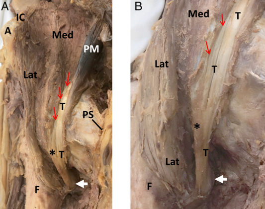
Figure 4: Anatomy of iliopsoas, anterior views. (A) Relationship of PM to medial and lateral parts of ILC. (B) Enlargement of PM tendon and medial and lateral parts of ILC showing attachment sites to the lesser trochanter. A, anterior superior iliac spine; F, femur; IC, iliac crest; Lat, lateral part of ILC; Med, medial part of ILC; T, tendon of PM; PS, pubic symphysis; *, tendon of ILC merging with T; white arrow, lesser trochanter; red arrow, fiber bundle attachments of medial part of ILC to PM tendon.
The anatomy suggests that a BoNT injection using the anterior approach would mostly target the ILC as the PM is primarily tendinous in this region. In a clinical study of children with CP, Ward reported that BoNT injection using a lumbar approach, through the paralumbar muscles without EMG or US guidance, was beneficial resulting in “a direct association between injecting PM muscles in spastic diplegics with hip flexor and adductor restriction, and the outcomes measured.” Reference Ward18,Reference Ward19 In our cadaveric study, using the US-guided lumbar approach, the injectate was localized within the PM muscle belly in all specimens, with one exception where there was minor extramuscular extension posteriorly which did not encroach any important structures. Furthermore, the injectate was within the region of the MEP zone between vertebral levels L3 and S1. Reference Van Campenhout and Molenaers9,Reference Van Campenhout, Verhaegen, Pans and Molenaers10 This provides additional support that the lumbar approach is superior in targeting the PM muscle belly consistently in the desired region of MEPs. In order to get the maximum control of the hip flexor spasticity, the combination of the anterior approach to capture the ILC and lumbar approach for PM would appear to be more effective. Further clinical studies are necessary to determine if the anterior approach or the lumbar approach or a combination of the two approaches provide the best outcome.
The perceived risk of injury to the AA, IVC, and/or kidneys has been a deterrent in the clinical use of the lumbar approach. Our study provided a unique opportunity to assess and visualize the injectate spread and affirmed that no vital structures listed above, particularly the AA and IVC, lying in close relationship to the vertebral column, were punctured or encroached by the dye spread. Earlier clinical studies used a blind injection technique; Reference Ward19 however, Westhoff et al. in a study of the anterior approach reported that US-guided injection provided better delineation of the relevant anatomy and allowed for visualization of needle advancement and injectate spread in real time. Reference Westhoff, Seller, Wild, Jaeger and Krauspe5 Furthermore, Karmakar et al. in a study of lumbar plexus block suggested that the use of US guidance could limit needle-related complications. Reference Karmakar, Ho, Li, Kwok, Tsang and Ngan Kee12
A limitation of this study is the small sample size. However, the labor-intensive and time-consuming process of dissection and digitization of dye spread prohibited a larger sample size. Also, the spread of injectate may not exactly replicate BoNT in vivo, although in the literature it has been reported that lightly embalmed specimens have similar tissue qualities to that in vivo. Reference Tsui, Dillane, Pillay, Ramji and Walji20 The recumbency versus upright position and physical movement of patients are the subjects of further studies as these factors can influence the characteristic spread of the injectate.
Conclusion
The injection of chemodenervation agents, such as BoNT, using the US-guided lumbar approach could target the proximal PM consistently without injury or spread to the AA, IVC, and/or kidneys. It is also expected, that in addition to the conventional anterior approach of injecting “iliopsoas,” the PM injection through lumbar approach could maximize the outcome of severe hip flexor muscle hypertonia/spasticity. This technique would be particularly useful in cases with severe hip flexion deformity which denies adequate access to the femoral triangle. Further clinical studies to compare the outcome of injecting ILC using the anterior approach alone, PM using the lumbar approach alone, and a combination of the two approaches are recommended to determine the optimal clinical protocol.
Acknowledgments
The authors would like to acknowledge the individuals and families who graciously donated their bodies and tissues for the advancement of education and research.
Conflict of interest
Dr. Anne Agur and Dr. Satyendra Sharma are anatomy faculty members of the Allergan Academy of Excellence. This affiliation is for teaching purposes only and has no relationship to the current study. Allen Duong has no disclosures.
Statement of authorship
AD performed the dissection and data collection, data analysis, and contributed in the writing of this manuscript. SS provided the framework for the pursual of this project, conducted the injections on the specimens, and contributed in the writing of this manuscript. AAMA has provided the equipment necessary for the pursual of this project, oversaw the data analysis, and contributed in the revision and writing of this manuscript.


