

1 Introduction
1.1 Motivation: the need for a method to design innovative products
A debate exists regarding the teaching and practicing of engineering design methods: Which is the ‘most correct’ method? Are some methods more suitable for teaching to novices and others that are practiced by accomplished designers? Do experts use structured methods or intuition and experience? Should the taught design methods be general or discipline-specific? Is there a preferred method when it comes to highly innovative design tasks, as opposed to more routine design?
One approach to answer these questions has been the study of the thought processes and activities of successful designers. Cross (Reference Cross2006) describes the study of three innovative designs by experts – engineering, product and race car designers. He concludes that they all identify quickly the crux of the design task at the conceptual level, generate an approach to solve it, then examine their solution and modify it. Common characteristics of designers’ strategies are also identified; for example, following a reasonably structured – yet flexible – process, occasionally behaving opportunistically, and frequent switching of types of cognitive activity. In a later book, Cross (Reference Cross2011) adds more strategies, such as incremental development, that is, retaining and pursuing partial, interim ideas and solutions and rarely forgetting or discarding them. Similar work has also been reported by other researchers. Lawson (Reference Lawson2005), for example, notes that designers often use solution-focused rather than problem-focused strategies, and that they quickly develop a rough idea for the most significant elements of the solution, which he calls the ‘primary generator’ idea.
Although this kind of research has undoubtedly contributed significantly to our understanding of human thinking in design, it falls short when it comes to translating the findings to a prescriptive model of the design process that can be taught and practiced. The most common general model presently taught in engineering is the German systematic design method (Pahl et al. Reference Pahl, Beitz, Feldhusen and Grote2007), sometimes referred to as the rational model. This prescriptive paradigm consists of distinct sequential stages, with functional decomposition and morphology for the conceptual design stage. This method seems to have been derived by logical reasoning and indeed its stages are seemingly sensible: begin by abstracting the need to define the main function, break down that function to subfunctions, find solution principles for each subfunction and finally, combine the individual ‘subsolutions’ into a product concept. However, this model has been the subject of some criticism in recent years (Kroll Reference Kroll2013).
In addition to general design methods, discipline-specific methods also exist, including those in aerospace engineering. Traditional aircraft design methods (e.g., Raymer Reference Raymer2012; Roskam Reference Roskam2003; Torenbeek Reference Torenbeek2013) work well when designing something that does not deviate much from previous designs or requirements. Such methods consist of highly refined optimization procedures that are based, to a large extent, on historical data and using them is efficient and effective when they are applicable. Raymer (Reference Raymer2012), for example, presents the selection of a wing’s equivalent aspect ratio (wing span squared divided by wing and canard areas) for three families of aircraft, as part of the initial layout development. For sailplanes this aspect ratio is given as 0.19 $(\text{best}\;L/D)^{1.3}$
, where
$(\text{best}\;L/D)^{1.3}$
, where $L/D$
is the lift-to-drag ratio. For propeller aircraft he lists numbers ranging from 6.0 for a homebuilt to 9.2 for a twin turboprop, and for jets he specifies another equation:
$L/D$
is the lift-to-drag ratio. For propeller aircraft he lists numbers ranging from 6.0 for a homebuilt to 9.2 for a twin turboprop, and for jets he specifies another equation: $\mathit{Equivalent~aspect~ratio}=aM_{\max }^{C}$
, where
$\mathit{Equivalent~aspect~ratio}=aM_{\max }^{C}$
, where $M$
is the Mach number and the coefficients
$M$
is the Mach number and the coefficients $a$
and
$a$
and $C$
depend on aircraft type (e.g., for a trainer,
$C$
depend on aircraft type (e.g., for a trainer, $a=4.737$
and
$a=4.737$
and $C=-0.979$
). Such ‘cookbook methods’ do not expose the user to the underlying physics: we do not know, for example, why for jets the aspect ratio should be exponentially linked to the Mach number, and the numbers listed for the relations are clearly not physical, but statistical.
$C=-0.979$
). Such ‘cookbook methods’ do not expose the user to the underlying physics: we do not know, for example, why for jets the aspect ratio should be exponentially linked to the Mach number, and the numbers listed for the relations are clearly not physical, but statistical.
Many other engineering disciplines use such structured methods, to which design theorists refer as ‘rule-based design’ (Le Masson, Weil & Hatchuel Reference Le Masson, Weil and Hatchuel2010) and contrast with ‘innovative design’. The former is characterized by having well-established techniques, guidelines and algorithms, while the latter may not have a systematic process that can be followed and may rely more on experience and intuition. Clearly, following the rule-based paradigm will likely result in a quick and less risky solution, but one that is similar to what has already been produced in similar situations.
Engineering design often starts with a need: a completely new aircraft design may be sought to implement a revolutionary idea or invention, a new design may be required because conventional technologies have reached their limit in satisfying the task requirements, or perhaps the task itself is completely new. Sometimes, an innovative design is needed for a subsystem or component for which no discipline-specific design method exists. Rigorously defining innovative design is beyond the scope of this article, but the literature on innovation presents many definitions and various contexts (e.g., Christensen, 1997). Some scholars contrast sustaining with disruptive innovation and others talk about radical vs. incremental innovation. The focus in the current article is on the type of innovative design that solves a problem that is relatively well defined but when the path to the solution is unclear, and this is sometimes referred to as breakthrough innovation, meaning that the solution represents a revolutionary approach or a paradigm shift.
What should the aerospace designer do in situations when a radically innovative solution is called for? To answer this question we resort to the well-established approach of looking at how expert aerospace designers work. Indeed, it may be argued that the ways of thinking of expert designers are not suitable for novices, and that the experts may not be using design methods at all, just intuition. But if we accept that experts may be a good source of learning – as argued, for example, by Schön (Reference Schön1987) – then we should examine their work; and to avoid the mere collection of disorganized and anecdotal insights, this study should use a predefined framework in which the cases will be cast. Therefore, our research hypothesis is that innovative design in the aerospace area is sometimes carried out by a thought process similar to the parameter analysis (PA) method. The implication of finding empirical evidence for this hypothesis is that PA may be claimed to be suitable for teaching and practicing innovative aerospace conceptual design in situations of radical, breakthrough innovation.
1.2 The PA method of conceptual design
Parameter analysis (Kroll, Condoor & Jansson Reference Kroll, Condoor and Jansson2001) is an empirically derived method for doing conceptual design. It was developed initially as a descriptive model after studying designers in action (Li, Jansson & Cravalho Reference Li, Jansson and Cravalho1980) and observing that their thought process involved continuously alternating between conceptual-level issues, called ‘parameters’, in the concept space and descriptions of hardware in the configuration space. The result of any design process is certainly a member of configuration space, and so are all the elements of the design artifact that appear, and sometimes also disappear, as the design process unfolds. Movement from one point to another in configuration space represents a change in the evolving design’s physical description, but requires conceptual reasoning, which is carried out in concept space. The elements of concept space – the parameters – are functions, ideas and other conceptual-level issues that provide the basis for anything that happens in configuration space. Moving from concept space to configuration space involves a realization of the idea in a particular hardware representation, and returning from configuration space to concept space is an abstraction or generalization, because a specific hardware serves to stimulate a new conceptual thought.
To facilitate the movement between the two spaces, a prescriptive model was conceived, consisting of three distinct steps, as shown in Figure 1. The first step, parameter identification (PI), consists primarily of the recognition of the most dominant issues at any given moment during the design process. These may include the fundamental physics governing a problem, a new insight into critical relationships between some characteristics, an analogy that helps shed new light on the design task or an idea indicating the next focus of the designer’s attention. Parameters play an important role in developing an understanding of the problem and pointing to potential solutions.

Figure 1. The prescriptive model of parameter analysis consists of repeatedly applying parameter identification (PI), creative synthesis (CS) and evaluation (E). The descriptive model of moving back and forth between concept space and configuration space is also shown.
The second step is creative synthesis (CS). It represents the generation of a physical configuration based on the concept recognized within the PI step. Since the process is iterative, it generates many physical realizations, not all of which will be very effective. However, the configurations allow the designer to see new key parameters, which will again stimulate a new direction for the process. The third component of PA, the evaluation (E) step, facilitates the process of moving away from a physical realization back to parameters or concepts. Evaluation is important because one must consider the degree to which a specific implementation represents a possible solution to the entire problem. Evaluation also uncovers the weaknesses of the configurations, helps to identify key parameters and indicates potential areas of improvement for the next design cycle.
Parameter analysis has been taught for over 25 years, mainly to mechanical engineering students, while the scope of the present work is aerospace engineering design. The requirement to explicitly state distinct PI, CS and E steps is for pedagogical purposes; it is expected that with enough training, practitioners would use this thought process even without adhering to the seemingly rigid presentation. Parameter analysis has also been the subject of more recent theoretical investigations using concept–knowledge (C–K) theory (e.g., Kroll Reference Kroll2013; Kroll, Le Masson & Weil Reference Kroll, Le Masson and Weil2014). These have formally shown that PA is particularly adapted to situations of radical innovation, where relevant design rules may be unknown and a knowledge expansion is required.
1.3 Case-study research methodology
How can we study the thought process of designers? Available design research methods, including the case-study methodology, have been described extensively by many researchers (Blessing & Chakrabarti Reference Blessing and Chakrabarti2009; Teegavarapu, Summers & Mocko Reference Teegavarapu, Summers and Mocko2008; Le Dain, Blanco & Summers Reference Le Dain, Blanco and Summers2013). The current research required the study of highly trained people in realistic settings, so it was implausible to conduct controlled experiments. Such experiments may not include the targeted innovators, may not last long enough to allow following the whole design process, and may not expose the designers to the same dilemmas as in real situations. It may be difficult to gain access to the inner working of real design projects in industry because of their often classified nature and business sensitivity of the work. It is also questionable whether it is possible to know a priori that innovative solutions will result from a project that just begins. We therefore chose to use the qualitative research methodology of case study, where data are gathered by inspecting specific cases and trying to extract certain patterns. Noor (Reference Noor2008) explains that such qualitative methods emphasize process and meaning while looking for insight, discovery and interpretation, as opposed to the rigorous quantitative examination of other methods.
Case studies are usually defined as objective (no involvement of the researcher), in-depth examinations of uncontrolled and complex phenomena (Yin Reference Yin2014). Yin also says that case-study research should be considered when: (a) the focus of the study is to answer ‘how’ and ‘why’ questions; (b) the behavior of those involved cannot be manipulated; and (c) you want to cover contextual conditions because you believe that they are relevant to the phenomenon being studied, or when the boundaries between the phenomenon and its context are unclear.
Our hypothesis involves the mental flow of ideas and the process of innovative design. Clearly, we are not interested in questions such as ‘how many’, ‘when did a particular event take place’, ‘who carried out a specific activity’, ‘how much’ and ‘what exactly happened’. These questions can be answered by a survey or archival analysis. We are more concerned with ‘how the design process unfolded’ and ‘why design flow took its shape’, and these kinds of question are suitable for case-study research. Yin’s second criterion deals with the ability to control the course of events. Innovative designs usually require a long time for incubation and evolution (on the order of weeks, months and even years), and involve highly experienced people, difficult tasks and the necessity to verify the feasibility of proposed designs. It seems almost impossible to perform controlled experiments under these circumstances. The context of design processes, as mentioned in Yin’s third condition, is widely accepted as inseparable by many design researchers. The design process is strongly linked to several factors: for instance, the initial requirements and goal, the designer’s character and style of work, his/her experience and knowledge, and the surrounding organizational and managerial environment.
Similar ideas have been expressed by others (Hancock & Algozzine Reference Hancock and Algozzine2006; Baxter & Jack Reference Baxter and Jack2008), who state that the qualitative case-study methodology provides tools for researchers to study complex phenomena within their contexts by deconstructing them through the collection of information from interviews, observations and documents. Kitchenham, Pickard & Pfleeger (Reference Kitchenham, Pickard and Pfleeger1995) advocate using case studies in software engineering, but warn that unlike formal experiments and surveys, case studies do not have a well-understood theoretical basis or the rigor of the former. Gerring (Reference Gerring2007) remarks that the case-study method survives in a ‘curious methodological limbo’ because it is poorly understood, and this stands in contrast to the fact that much of what we know about the empirical world comes from case studies. Flyvbjerg (Reference Flyvbjerg, Denzin and Lincoln2011) points to exactly the same paradox, and proceeds to list and correct five common misunderstandings about case studies: (a) general, theoretical (context-independent) knowledge is more valuable than concrete, practical (context-dependent) knowledge; (b) it is impossible to generalize on the basis of an individual case; (c) case studies are most useful for generating hypotheses, not testing them or building theories; (d) case studies contain a verification bias; and (e) it is often difficult to summarize and develop general propositions and theories on the basis of specific case studies.
2 Developing the case-study methodology for the current research
For all of the above reasons, the case-study methodology seemed to be the most appropriate for the current research. It was used to collect the data, analyze them, search for patterns within the data and draw conclusions. We did not create the original case narratives for this research; rather, we used written documents and publicly available video lectures and websites as our data.Footnote 1 Therefore, the presentation of the case studies in this paper is actually a reconstruction with a specific framework, as explained below.
Yin (Reference Yin2014) proposes the following guidelines for a successful case-study research: define the goal through the research question, establish the propositions and the units of analysis followed by forming the logic that links the data to the propositions, and finally, select the criteria for interpreting the findings. Our research goal was to find a suitable approach to teach conceptual design for innovative tasks and to novice designers. Following Baxter & Jack’s (Reference Baxter and Jack2008) advice on not attempting to answer too wide a question, we posed the research question of how innovative designs are carried out by expert aerospace designers as reported by various sources. The research propositions that followed were that a thought process similar to PA is used, even if unknowingly, and that this can be tested and demonstrated by finding unique characteristics of PA in the reported case studies. The unit of analysis was therefore the design process or flow, and not, for example, the individual designer’s background (experience, formal education and influences) or the design team’s characteristics (data flow among members, work sharing and social interaction). In addition, we ignored the success or failure (commercial or other) of the product, technical details that did not serve to explain the conceptual design process, and competing designs.
How to link the data collected from the case studies to the research propositions was a major concern. We have decided to establish a list of eight characteristics of PA and look for their presence in the case studies by pattern matching. Finally, the success criterion has been defined as the number of PA characteristics that could be found in the case studies. Since the eight characteristics listed below are not mutually exclusive and were defined to provide good coverage of cases described by different sources and in various styles, we initially decided that the presence of at least half of the characteristics (four out of the eight) would be considered a success. The list of PA characteristics, their meaning and the way we looked for them is as follows:
-
(1) Three-step process. The most distinct characteristic of PA, one that distinguishes it from other design methods, is that the design process appears to consist of a chain of repeated PI–CS–E steps. To show that a design process from a case study follows this pattern, we required that it would be possible to translate the collected data into such a sequence of steps. Hence, the case studies of this paper will be presented in the PI–CS–E format, meaning triplets of concept–configuration–evaluation. The issue of a seemingly circular argument concerning this characteristic is addressed in Section 4.1.
-
(2) Iteration. Design is iterative by nature, and traditional methods, such as the rational model, accommodate it by introducing the possibility of backtracking between stages. A failure in the detail design stage, for instance, may direct the designer to return to embodiment design or even to conceptual design to fix the problem. However, in this research we deal only with the conceptual design stage and iteration in the context of PA means that problematic aspects are continuously identified and fixed, often resulting in a nonlinear path from beginning to end. We shall therefore look for evidence in the case studies for backtracking and retraction of earlier decisions during the design process.
-
(3) Alternating between spaces. Designs are usually described by an evolving structure or configuration. In contrast, an important characteristic of PA is that ‘movement’ from one configuration to another cannot be carried out directly, but through a ‘visit’ to concept space. We shall search for evidence that the thought process of the designer alternates repeatedly between the domain of ideas – the concept space – and the domain of structure representations (i.e., a sketch, model, prototype or results derived by an experiment or calculation) – the configuration space.
-
(4) First principles. The emphasis put by PA on identifying conceptual-level issues, parameters, in each cycle also brings about reliance on first principles and the fundamental physics of the problem. Designing from first principles has also been observed by other researchers who studied the innovative work of expert designers through interviews and protocol studies (Cross Reference Cross2006). Parameter analysis encourages thinking in conceptual terms, frequently identifying the governing physics as dominant and critical parameters. This helps develop a sense and intuition for the situation at hand and often dictates that complex mathematical relationships and equations are simplified to highlight only significant and relevant aspects.
-
(5) Parameter identification. The key to successful design, according to PA, is the identification of critical and dominant conceptual-level issues (parameters) throughout the design process and focusing on a single parameter at any given moment. This is quite different from the approach of functional decomposition and morphology, for example, where all the functions and their solution principles are handled simultaneously. In PA, the designer’s knowledge and experience often express themselves as a ‘bag of tricks’ that helps to identify new parameters.
-
(6) Steepest-first development. A distinct feature of PA is that during each cycle, the most critical and dominant parameter should be identified and realized in a configuration, as opposed to just any parameter. The purpose is to increase the likelihood of success: function–form dependencies are unavoidable, so less important issues – those likely to be solvable – should be handled last and conform to earlier, more dominant decisions regarding the more difficult aspects of the design task. This translates into identifying, at any given moment, the critical conceptual-level issue associated with the highest uncertainty and focusing on it. The result is a development process called ‘steepest-first’ (Kroll et al. Reference Kroll, Le Masson and Weil2014), which is similar to a depth-first graph traversal but with a very specific ordering of the nodes to be expanded first. This is in clear contrast to the breadth-first approach of functional decomposition and morphology in systematic design.
-
(7) Minimalistic configurations. An important characteristic of PA is that the configurations generated in each cycle should not be more elaborate than what is necessary for evaluating them. This ensures efficiency of the process and prevents obscuring the important aspects of the design with too many details. Using rough, simple ‘back-of-the-envelope’ calculations, sketches and diagrams keeps the focus of the conceptual design process on the ideational aspects, as dealt with in concept space, while the structural representation in configuration space serves mainly to facilitate the evaluation of the evolving artifact.
-
(8) Constant evaluation. In traditional design methods, especially those that follow the rational model, design is depicted as consisting of analysis (of the task), synthesis (of solutions) and evaluation (selecting among possible solutions and checking whether the requirements are satisfied). By ‘evaluation’ in the context of PA we mean something different: it is a step that is constantly applied and is expedited by having configurations that realize ideas. Hence, evaluation plays an important role in examining the evolving design solution and pinpointing the direction for improvement in the next PI–CS–E cycle.
The case studies selected for this research are likely to be considered innovative by most practitioners in the aerospace field, mainly for being very different from their predecessors. Their design processes had to have reasonable coverage in various documents, as opposed to descriptions of the final outcome only. We were particularly interested in having a variety of designs among the cases; all should be related to aerospace engineering but cover different types of product.
3 Description and analysis of the case studies
The four case studies are presented below in the chronological order in which they took place. Each one begins with a brief introduction, followed by a description of the relevant portion of the design process cast in the PI–CS–E format and concludes with an analysis of the findings.
3.1 Case study I: Wallis’ bouncing bomb
During World War II, the British engineer Sir Barnes Wallis designed 5- and 10-ton ‘Earthquake’ bombs to destroy strategic German targets. These bombs were dropped from ${\sim}$
40,000 ft and could penetrate up to 40 meters of soil before detonating and producing powerful shock waves. He then addressed the problem of destroying hydro-electric dams used in the German steel-making industry, by developing the ‘bouncing bomb’ technique for that purpose. Several years of development effort culminated in Operation Chastise on May 16–17, 1943 with the successful breaching of two major Ruhr Valley dams and damaging a third. In spite of heavy British losses – 8 out of the 19 aircrafts were lost, 53 crewmen died and 3 were captured – the project has been considered a big success. The description here is based on Brickhill (Reference Brickhill1999) and Murray (Reference Murray2009):
${\sim}$
40,000 ft and could penetrate up to 40 meters of soil before detonating and producing powerful shock waves. He then addressed the problem of destroying hydro-electric dams used in the German steel-making industry, by developing the ‘bouncing bomb’ technique for that purpose. Several years of development effort culminated in Operation Chastise on May 16–17, 1943 with the successful breaching of two major Ruhr Valley dams and damaging a third. In spite of heavy British losses – 8 out of the 19 aircrafts were lost, 53 crewmen died and 3 were captured – the project has been considered a big success. The description here is based on Brickhill (Reference Brickhill1999) and Murray (Reference Murray2009):
- PI:
-
Dams do not have soil around them to produce shock waves, and detonation in the air is ineffective because the shock waves would dissipate quickly. Use the water near the concrete dams to conduct the shock waves from the bomb explosion to the structure.
- CS:
-
Calculations show that a 10-ton bomb exploding 15 meters from a dam (a precision that seemed attainable) will create a 30-m opening in the structure. Experiments start on small specially built dams but result in many failures.
- E:
-
Analyzing the failures shows that a 30-ton bomb will be required, and this is clearly unfeasible (no aircraft to carry it).
- PI:
-
A substantially smaller bomb can be used if it exploded while touching the dam, but this requires very precise dropping of the bomb.
- CS:
-
This can be accomplished with either torpedoes or flying very low and hitting the dam directly.
- E:
-
The dams are protected by torpedo nets in the water. Dropping the bomb from very low may make it bounce off the water surface because the trajectory is almost horizontal, thus missing the dam.
- PI:
-
Use precise bouncing of the bomb to hit the dam, sink to its bottom and then explode.
- CS:
-
Experiments begin in a small pond with a homemade throwing device and, at the same time, exploding charges adjacent to a dam model. Results show that 3 tons of explosive (new RDX) will blow up a dam. Add 1.5 tons for the casing, and the bomb is less than 5 tons. It is possible to carry it by a Lancaster bomber. Many experiments continue, bomb diameter set to 210 cm, and the bomb spun ‘backwards’ at 500 rpm before dropping it to ensure it reaches the bottom of the dam and not ‘climb’ over it (Figure 2).
- E:
-
If the height when releasing the bomb is not precise, the bomb can explode when hitting the top of the dam and possibly damage the airplane, or bounce over the dam.
- PI:
-
The airplane’s altimeter is not accurate enough (and also, the barometric conditions over the target are unknown), radar altimeters are also inaccurate. Suspend a rope with a weight at its end and watch it touch the water surface to detect the height.
- CS:
-
Experiments with such a device are carried out.
- E:
-
The rope becomes almost horizontal during flight and does not touch the water. Another method is required.
- PI:
-
Use triangulation with two projectors whose spots can be seen on the water surface, as already experimented with by the Royal Air Force.
- CS:
-
Spotlights are installed on the Lancaster to allow flying at 60 ft when the light circles become tangent and form a figure eight. A crew member looking down guides the pilot.
- E:
-
Clearly, it is very dangerous to turn on the lights, but the method works. What about releasing the bomb at the exact distance from the target?
- PI:
-
Use the known distance (from aerial photos) between the dam towers for a mechanical aiming device based on the principle of similar triangles.
- CS:
-
A wooden sight with two nails and an eyepiece is designed for measuring the 400–450 yd range. It is tested with eight training bombs.
- E:
-
An average miss of 3.5 yd in testing means that the solution is satisfactory.

Figure 2. Method of attacking dams with a bouncing bomb; adapted from (RAF Museum 2013).
Analysis: It is quite clear from this short presentation of a relatively long development process that it follows the three-step process (concept–configuration–evaluation) characteristic. It also demonstrates an iterative nature of trying various solutions and backtracking when failure occurs. When early scaled-down experiments show that an impractically heavy bomb is required, it leads to the alternative approach of detonation while touching the dam. The failure of experiments with the rope-and-weight device leads to seeking another solution for height measurement. Basic physics and mathematical principles are used throughout, so the first-principles characteristic is present. For example, understanding of blast impact in water and near structures is developed theoretically and empirically; triangulation for altitude control and similar triangles for distance measurement are used. Dominant and critical issues – the PI characteristic – are used at each stage, from deciding on the basic method of bringing the bomb to the vicinity of the dam, through exploring the required weight of explosive, to verifying that the bomb sinks to the bottom of the dam instead of skipping over it. Wallis’ utilization of shock waves is reported to have been inspired by seeing the destruction of concrete pylons being driven into the bed of the Thames while building the Waterloo Bridge. The bouncing bomb idea is reported to have its seeds in the practice of naval gunners to deliberately skip cannon balls over the water to extend the range (Murray Reference Murray2009). The order of addressing the critical issues clearly follows the steepest-first development characteristic; e.g., bombing sights are developed only after the mechanics of dropping the bomb has been resolved. In contrast, some of the characteristics of PA are not very pronounced in this case study. Alternating between concept space and configuration space, using minimalistic configurations, and constantly evaluating the evolving design are only hinted at.
3.2 Case study II: Gossamer Condor human-powered plane
On August 23, 1977, Paul MacCready’s human-powered Gossamer Condor won the £50,000 Kremer prize (set up in 1959) for flying a figure eight course around two markers one half mile apart, starting and ending at least 10 ft above the ground. This unorthodox aircraft is considered to be the first human-powered plane capable of controlled and sustained flight. The Gossamer Albatross, a similar aircraft also designed by MacCready, won the second Kremer prize two years later for the first human-powered flight across the English Channel. The following reconstruction of part of the design process is based on Burke (Reference Burke1980), Lambie (Reference Lambie1978) and MacCready (Reference MacCready2003):

Figure 3. Power output vs. time for human cycling, rowing and combined cycling and hand cranking; adapted from Burke (Reference Burke1980). (Reprinted with permission of the American Institute of Aeronautics and Astronautics, Inc.)
- PI:
-
Human power output vs. time has been studied in the past and is given as in Figure 3. Flying slowly will take longer to complete the course, but the required power can be reduced considerably. Locate the operating point on the asymptote, around the 0.5 hp value, which can be sustained for many minutes.
- CS:
-
The course is about 1.5 miles long. If the speed is set at ${\sim}$
8 mph, the duration would be
${\sim}$
10 min and the required power
${\sim}$
0.4 hp. Takeoff and climb would require more power, but only for a very short duration.
${\sim}$
8 mph, the duration would be
${\sim}$
10 min and the required power
${\sim}$
0.4 hp. Takeoff and climb would require more power, but only for a very short duration. - E:
-
A cycling pilot can produce the required power, but can the airplane be designed around this operating point?
- PI:
-
The power
$P$
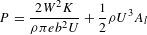
needed for sustained level flight can be expressed, among several other ways, as
$$\begin{eqnarray}P=\frac{2W^{2}K}{{\it\rho}{\it\pi}eb^{2}U}+\frac{1}{2}{\it\rho}U^{3}A_{l}\end{eqnarray}$$
where
$W$
is the weight,
$K$
is a ground effect factor,
${\it\rho}$
is the air density,
$e$
is a span efficiency factor,
$b$
is the wing span,
$U$
is the speed, and
$A_{l}$
is the equivalent flat-plate drag area. The first, induced-drag, term shows the importance of low weight and large span while the second, parasite-drag, term shows that speed should be low. - CS:
-
With the speed set at 8 mph, the span is set at 95 ft (so the aircraft can fit in the available hangar) and the cord at 12 ft.
- E:
-
Assuming reasonable powertrain and propeller efficiencies, calculations show that there is a good power margin at the required duration. But can such a large, light and efficient airplane be built?
- PI:
-
Use lightweight materials and efficient structures.
- CS:
-
Wire-braced aluminum tube structure inspired by hang gliders, with the pilot ‘suspended’ on tension-carrying members, and a single-surface airfoil made of Mylar in a canard configuration is built and tested (Figure 4).
- E:
-
Aerodynamic and structural principles have been well demonstrated, but the wing is too sensitive to changes in angle of attack: during testing it is found that separated flow regions develop near the leading edge. This is caused by lack of rigidity of the airfoil as evident from the trailing edge distorting and the Mylar skin failing to maintain the required shape.
- PI:
-
Make the wing more rigid by switching to a full two-surface airfoil and adding a rear spar.
- CS:
-
A two-surface airfoil is implemented and testing carried out.
- E:
-
Control problems related to performing turns are discovered.
- PI:
-
The airplane does not have vertical control surfaces, and adding them will increase the drag. Turning by slanting the lift vector can be done by tilting the front horizontal stabilizer.
- CS:
-
Fish-line strings are attached to the stabilizer tips so that in addition to pitch control, the surface can be tilted.
- E:
-
This worked almost well enough in testing, without additional weight or drag, but roll damping is making maneuverability sluggish.
Figure 4. The structure of the Gossamer Condor (Copyright Don Monroe).
- PI:
-
Differing local angles of attack across the span create a torque opposite the steady roll direction, and additional torque is required in accelerated roll of the wing due to the momentum imparted to the air (‘apparent additional mass’). Wingtip chord should be reduced to overcome these problems.
- CS:
-
A tapered planform is designed, built and flight tested.
- E:
-
With the reduced area of the new wing, the airplane needs to fly a little faster (
${\sim}$
10 mph) to produce the required lift, thus increasing parasite drag. - PI:
-
Reduce parasite drag by smoothing the configuration.
- CS:
-
Mylar fairing is installed around the previously exposed pilot and testing resumes.
- E:
-
Turning problems persist, resulting in a crash.
- PI:
-
Calculating the required angle-of-attack distribution across the span with the wing in level turn shows that the dynamic pressure at the inner tip is only half of that at the outer tip. To have more incidence of the inner wing, reverse twisting of the wing must be used.
- CS:
-
Wing-twist control is implemented with a pilot-operated lever that pulls differentially on the outer flying wires, thus altering the incidence of the wing tips.
- E:
-
Smooth coordinated turns are now possible, as confirmed by pilot observations of streamers attached to the stabilizer. Aerodynamic development of the configuration is complete.


Analysis: From this description of part of the design process we can see the three-step reasoning process. The iterative nature of the work is apparent from the many unsuccessful attempts to solve problems. For example, describing the struggle to overcome the turning problem, Burke (Reference Burke1980) writes: We tried upper-surface spoilers, drag-producing ailerons, pendant rudders and, finally, a banking stabilizer for control… Relying on first principles and basic physics accompanies the design process throughout: from understanding the power–time relationship and using the specific power equation that emphasizes certain influences, through employment of efficient structural principles, to exhibiting outstanding comprehension of aerodynamic and control issues. At any moment during development, the designers focus on a single main issue, thus demonstrating the PI characteristic. They start with power availability and establish the baseline configuration and operating point, then the construction of a lightweight and efficient structure, followed by aerodynamics and flight mechanics. The order in which these major issues are addressed clearly follows the steepest-first criterion, as testified by Burke (Reference Burke1980): …it seemed at the outset that we would be able to come up with some scheme for getting around the turns, so we concentrated, at first, on straight flights to work out the more basic problems of power available and required.
The Condor designers employ minimalistic configurations: Lambie (Reference Lambie1978) states that the first conceptual idea for the Condor was drawn on a napkin, and throughout the process it is apparent that the designers kept tweaking the aircraft by implementing only a single change at a time and quickly testing it. Complications are avoided by postponing unnecessary decisions (e.g., using small toy wheels when these are needed, or covering the cockpit with a fairing), as stated by Burke (Reference Burke1980): We attacked only the most obvious problems, intending to deal with others if and when they arose. Alternating between spaces and constant evaluation are not as evident as the other characteristics of PA in this case study.
3.3 Case study III: Rutan’s Boomerang
This 1996 unique asymmetric configuration claimed improved performance (especially speed and range), safety and fuel efficiency over other comparable twin-engine planes. Rutan, who has designed dozens of aircrafts over a 45-year career, is often quoted as saying that the Boomerang is his favorite design and the most significant general aviation airplane he has ever done. Chapter 2 in Linehan (Reference Linehan2011) and Rutan Boomerang (2015) quote Rutan in explaining the design process, part of which we reformulate here:
- PI:
-
Improve the engine-out safety and cabin noise compared to existing conventional twin-engine configurations (e.g., Beech Baron 58) by relocating the engines asymmetrically to the fuselage and away from the cabin. Moving one engine away from the plane’s center of gravity can reduce the P-factor yawing effect (shifting of a propeller’s thrust vector under high angle of attack and power conditions, such as during takeoff); and the further an engine is moved, the lower the cabin noise.
- CS:
-
The left engine is moved outboard, producing an asymmetric layout (Figure 5 a).
- E:
-
Minimum control speed (MCS) is too high: failure of the right engine will produce too much yawing moment due to the long moment arm of the left engine.
- PI:
-
Reduce MCS by moving both engines inboard.
- CS:
-
The right engine is moved inboard and forward to clear the fuselage; the left engine is moved inboard and aft to balance (Figure 5 b).
- E:
-
The right engine is not supported well by the right wing; the left propeller interferes with the fuselage.
- PI:
-
Solve these problems by skewing both wings and leaving the engines in their current position.
- CS:
-
The wings are skewed to support the engines and to reduce the left engine interference (Figure 5 c).
- E:
-
For considerably better performance (speed and range) than a conventional twin-engine plane, a more sailplane-like configuration with a high lift-to-drag ratio is desired.
- PI:
-
Make the wings more slender by employing composite materials to provide the required strength and rigidity.
- CS:
-
Higher aspect ratio wings are designed, but the configuration is now nose-heavy. The left wing is swept forward to move the center of pressure forward (Figure 5 d).
Figure 5. Evolution of the Boomerang configuration; adapted from Rutan Boomerang (2015).
- E:
-
The plane is still nose-heavy.
- PI:
-
Reduce the weight further by making the fuselage of composites too, which will also allow using smaller engines. The tail area can be reduced to lower the drag.
- CS:
-
A filament-wound carbon fiber fuselage is designed; smaller and lighter engines and a reduced tail area are employed (Figure 5 e).
- E:
-
The high aspect ratio tail may have a flutter problem.
- PI:
-
Stiffen the tail by adding beam support.
- CS:
-
Nacelle boom is added (Figure 5 f).
- E:
-
There is now added baggage room in the boom, but weight, cost and drag are still too high.
- PI:
-
Solve these problems by moving the right engine to the fuselage.
- CS:
-
The right engine is located in the fuselage and the entire wing is moved to the left for lateral balance (Figure 5 g).
- E:
-
MCS is now well below stall, but the left engine is too close to the fuselage, causing propeller interference and cabin noise.
- PI:
-
Move the left engine further outboard.
- CS:
-
The left engine is shifted outboard and the entire wing is moved left for balance (Figure 5 h).
- E:
-
Low-speed handling is not good enough.
- PI:
-
Add a vertical tail surface to improve handling.
- CS:
-
Twin small vertical tails are used instead of the large single surface; the fuselage is rounded and some other details are improved (Figure 5 i).
- E:
-
The design is satisfactory.

Analysis: A clear flow of the three-step process and its iterative nature, where various attempts are made time and again to solve the major problems, can be observed. For example, moving the engines relative to the fuselage occurs several times until a satisfactory configuration is obtained, and this in turn requires multiple repositioning of the wing. Alternating between concept and configuration spaces appears in this design process as using clear concepts and ideas to support each structural change. These ideas rely on fundamental principles of flight mechanics, aerodynamics and structural engineering (e.g., the asymmetric blade effect in propellers, wing aspect ratio and beam support), thus exhibiting the first-principles characteristic. Explicit parameters drive the evolution of the design, maintaining minimalistic representations of configuration, and controlling the process with constant evaluations. The only PA characteristic that is not apparent in this process is steepest-first development, as there does not seem to be a particular ordering of the issues handled. Overall, seven out of the eight characteristics exist in this case study.
Interestingly, the portion of the Boomerang design process presented here may seem like an optimization effort, with many steps producing small changes in the configuration. However, the fact that the final aircraft is so unusual and different from the initial conventional twin-engine configuration justifies regarding it as a process of conceptual design.
3.4 Case study IV: Rutan’s SpaceShipOne
This suborbital spacecraft was the first to complete a manned private spaceflight, for which it won the $10 million Ansari X Prize in 2004 for reaching a height of 100 km twice within two weeks. SpaceShipOne is now on display at the Smithsonian Institution’s National Air and Space Museum. The design has later evolved into SpaceShipTwo, capable of carrying two crew members and six passengers, to pioneer space tourism. The following partial description of its design process is based on Chapter 4 in Linehan (Reference Linehan2011), Linehan (Reference Linehan2008) and Firth (Reference Firth2011):
- PI:
-
The traditional method of launching spacecraft from the ground with a rocket is expensive, not easy to reuse, and requires complex control by thrust vectoring. A spacecraft can alternatively be raised to a considerable altitude by a helium-filled balloon or another airplane, and launched from there. Use a carrier aircraft.
Figure 6. The White Knight turbojet aircraft with SpaceShipOne attached below (Courtesy of Scaled Composites, LLC).
- CS:
-
The White Knight carrier aircraft is designed to launch SpaceShipOne at about 50,000 ft (Figure 6).
- E:
-
This may work for launching the spacecraft, but how will it land?
- PI:
-
There are several possibilities. Parachutes are simple and low cost, but controlling the exact landing site is difficult and hitting the ground may be rough. Landing at sea requires expensive equipment and manpower for recovery. Propulsion-assisted descent allows controlling the landing location, but will add considerably to the launch weight. Finally, gliding may be a good option.
- CS:
-
Gliding descent and landing is investigated to determine the appropriate aspect ratio, drag, wing area and stability attributes, and to establish the configuration.
- E:
-
It proves successful, inexpensive and minimalistic in terms of weight. But how will the spacecraft re-enter the atmosphere?
- PI:
-
The traditional approach of adding an insulating or ablative heat shield will add weight and be expensive. The heat buildup is relevant to re-entry at high velocities, typical of orbiting spacecraft, but in the present case it may be possible to create a large aerodynamic drag at high altitude, where heat buildup is relatively small due to the slow speed and the very thin atmosphere.
- CS:
-
A feathering configuration that folds the back half of the wings, including the outboard tail sections, is developed. SpaceShipOne thus points a large surface area into the airstream for retarding the acceleration with minimal heating (Figure 7).
- E:
-
This will work, but what happens in case of mechanical failure of the feathering mechanism? This is a major safety concern.
- PI:
-
This aspect of the mission is so critical that redundancy should be designed into the mechanism.
Figure 7. Feather extended prior to re-entry.
- CS:
-
Extra actuators and locking mechanisms are added.
- E:
-
Safety is improved now, but how will the spacecraft accelerate after being launched from the carrier aircraft?
- PI:
-
Air-breathing engines will not work at very high altitudes, so a rocket motor is required. Solid-fuel rockets are simpler, but cannot be turned off, so safety is hindered. Liquid-fuel rockets require cryogenic storage and equipment (pumps, valves, etc.) and this would increase the cost and reduce reliability. Use a hybrid motor with solid fuel and liquid oxidizer.
- CS:
-
A specific motor is developed, using synthetic rubber fuel and
$\text{N}_{2}\text{O}$
oxidizer, producing 16,800 lbs of thrust. - E:
-
The efficiency of the motor is not that high, but it satisfies the requirements and provides a simple, inexpensive, safe and reusable solution.


Analysis: As in the previous case studies, the three-step reasoning process is evident from our formulating it as concept–configuration–evaluation triplets. Alternating between spaces is demonstrated by each cycle of development initially having an explicitly stated concept, idea, followed by realization in specific hardware. We can see that four major design aspects are dealt with in this example – launch, rocket propulsion, re-entry and landing – demonstrating PI: focusing on critical issues one at a time and ignoring others. The steepest-first development characteristic, addressing the most demanding tasks first, is also evident. For example, reaching space is handled first, but only to the point of deciding on using a carrier aircraft. The rocket-assisted stage is not perceived at that moment as the most critical issue; rather, landing, followed by re-entry are. Use of first principles is apparent in Rutan’s understanding of the speed change required by ground-based launch vs. aerial launch, and by using heating and aerodynamic drag considerations for decelerating upon re-entry.
4 Discussion
4.1 The research results
Table 1 summarizes the presence of the eight predetermined PA characteristics in the four case studies, showing that at least five were identified clearly in each case. Three characteristics were present in all the cases: the three-step process, first principles and parameter identification. The first is obvious and expected because during the data collection phase of this research we included only those cases that looked like they could be formulated as sequences of concept–configuration–evaluation triplets. Using only those case studies and later claiming that all of them exhibit the three-step process characteristic may seem to be a circular argument. However, it must be remembered that we also looked at other case studies whose narratives did not include the information we sought, and that the only way to show the presence of the three-step process characteristic is to actually rephrase the case description in this framework.
Table 1. Presence of PA characteristics in the case studies.

We were somewhat surprised by the use of first principles and clear identification of parameters (concepts and ideas), as we had expected the literature-based descriptions to focus more on the hardware and less on the ideational drivers in the thought processes. It seems that the expert designers exhibited an interesting approach of abstracting the configurational aspects of evolving solutions and replacing them with conceptual-level examinations and identification of critical issues. These issues, in turn, seemed to be based on the understanding of fundamental physical principles and their mathematical representation, and not on haphazard recollection of experience-based facts.
Iterations and steepest-first development were apparent in three of the four case studies. The former implies that several attempts were described at solving some of the problems before converging to a solution, and the latter means that the expert designers tended to focus on the more difficult aspects of the problem at any given time. Both of these characteristics did not come as a surprise, since they are typical of the thought process of experienced designers. Alternating between concept space and configuration space and using minimalistic configurations were identified in two of the case studies, while constant evaluation was obvious only in the Boomerang case. How can evaluation be absent from the design process? We attribute this result to the way authors of case studies tend to describe them: they focus on the evolution of the designed artifact, sometimes on the ideas behind it, but rarely seem to explicitly state the outcome of evaluations. However, the fact that we were able to list evaluation steps in the formulation of the case studies as PA means that evaluation was an important driver of the design processes.
In summary, the eight characteristics are not completely independent; for example, process iterations may indicate that constant evaluation was applied. However, we tried to mark a characteristic as present only when strong, direct evidence was found. This means that some characteristics that may have been present in the real cases do not show up in our results because the narratives used as sources of data did not emphasize them. On the other hand, there are instances when further support for our interpretation of the data is explicitly provided by the original case description, as demonstrated by the quotations in the analysis part of Section 3.2.
4.2 The research methodology
The case-study research methodology is quite common in the social sciences, psychology and business administration, and is generally considered appropriate for investigating mental processes, decision making and organizational behavior. It is much less prevalent in engineering, but may offer some advantages to this field too. The methodology enables researchers to obtain valid results, even general conclusions, from a case or cases that are not necessarily representative of a whole population. It also offers a holistic view of the subject and the emergence of new insights, while allowing the research to be carried out at a later time than the occurrence of the case.
Limitations of case-study research should also be noted. Pettigrew (Reference Pettigrew and Lawler1985) states that this methodology is under criticism because the data are wide and complex, cannot be mathematically or statistically proven, and also subjected to interpretation or can inadvertently be biased by the researcher. The most obvious issue is the subjective nature: the choice of which specific data to collect from the wide range of possible sources can considerably affect the results. Indeed, we sometimes had to resort to ‘detective work’ when searching for clues within the data to discover, for example, an evaluation step hidden in a comment or a figure caption. Analysis of the data may also tend to have a confirmation bias; that is, looking only for results that confirm the hypothesis. As opposed to the common scientific principles of conducting experiments that are repeatable and have control groups, with case-study research every case is unique, the circumstances are one of a kind, and controls are irrelevant.
Another possible shortcoming of case-study research may be the authenticity and reliability of the data. We are more likely to hear about successful designs than ones that may be just as interesting methodologically but less fruitful. Retrospective accounts of those designs may also tend to ‘glorify’ certain aspects; for example, emphasize sparks of ingenuity over hard, rigorous work. The people involved in the original work may not be available for double checking the facts, or they may not remember every detail. The 1954 movie The Dam Busters shows Barnes Wallis coming up with the idea of using two spotlights for measuring the height above the water level from stage lights while watching a theater show. Murray (Reference Murray2009) notes, however, that this is entirely fictitious, as the technique had been tried before by the British military for low flying over the sea. As another example, the reason for backspinning the bouncing bomb is still debated to date (Murray Reference Murray2009), with many possible explanations, from imitating cricket balls (backspin makes them bounce higher on the pitch), through stabilization by gyroscopic effect and adding aerodynamic lift by the Magnus effect, to producing a motion of the bomb toward the dam in case of slight undershot or overshot.
Finally, a disadvantage of case study is the extent of generalization that can be achieved. On the one hand, it is an investigation of a single or few cases, offering an in-depth understanding of only those occurrences with no comparison with other cases or a statistically reliable substantiation of the conclusions. On the other hand, if the same conclusions can be drawn from different case studies, then it should be possible to attempt at least a partial generalization. This generalization should be carefully stated and limited to cases that share the same common aspects of the case studies investigated.
4.3 The PA framework
As a design method, PA is prescriptive. However, here it is used to look at and explain the thought process of the innovators; hence it can be regarded as descriptive, or a theory. Successfully casting the case studies in the PA framework provides empirical evidence for the claim in the research hypothesis in the sense that it showed PA’s applicability to innovative aerospace design by demonstrating its implicit use by the expert designers. However, looking at PA as an explanatory theory can be used to answer broader questions related to its applicability (Hatchuel et al. Reference Hatchuel, Le Masson, Weil, Agogué, Kazakçi, Hooge, Chakrabarti and Lindemann2016): Can the design practices in the case studies reveal possible improvements that can enhance the current model of PA? Can one find practices that did not use a process similar to PA or did not use it fully, but could have benefitted from doing so? Can the PA framework reveal aspects of the innovators’ design process that were not explicitly stated in the primary data?
These questions are interesting because they show that in addition to using PA to analyze the case studies, the approach of this paper can also be used to confirm theoretical aspects of PA. For example, it may seem that the experts merely use intuition-based trial and error, or the more positive ‘try and learn’ approach in their work. However, based on the analysis of PA in Kroll, Le Masson & Weil (Reference Kroll, Le Masson and Weil2014), we can relate the innovators’ thought process to a more sophisticated strategy of alternating between high-level abstract knowledge (ideas including first principles) and low-level detailed knowledge (specific implementations as hardware), and doing so in a particular order (steepest-first) that attempts to minimize their effort.
Further, the absence of explicit evaluations in the case-study narratives, which we attributed to the way the authors chose to report them, can also be interpreted as the inability of the experts to explain their own thought process. Here PA can contribute a more concrete model of evaluation, which includes comparing the current artifact to the design requirements, generating new evaluation criteria, rating the solution relative to previous ones, and making decisions accordingly (Kroll, Le Masson & Weil Reference Kroll, Le Masson and Weil2014). This logic of evaluation can then be hypothesized to describe the work of the innovators, even without direct proof, and be added to the knowledge we expect the novices to learn.
5 Conclusion
This paper investigated, through case studies, whether the PA method of conceptual design is suitable to aerospace engineering. It showed that expert designers in this field, when called upon designing highly innovative solutions, use a thought process that shares many characteristics with PA. We can therefore conclude that if we look for a design method in situations that require innovation – when conventional aerospace design methods and general design methods (e.g., systematic design) are inadequate – and we believe that one source of learning how to design is the experts in the field, then PA is a good candidate for such a method.
In fact, PA had originally been developed empirically, based on observing designers, so the conclusion is not surprising; rather, the current research confirms the suitability of PA to aerospace design, under the limitations of the research methodology used. Hence, it cannot be claimed that PA is the only process for the job, nor that all aerospace innovators use a similar process. However, PA emerges as a good option for teaching aerospace design in addition to the traditional methods.
Although the case-study research methodology offers unique possibilities in design research, the researcher using the case-study approach needs to have greater responsibility in applying it due to the risks of subjectivity and vulnerability to bias, questionable authenticity and reliability, and uncertain level of generalization.
Financial support
This work was supported by the Israel Science Foundation (E.K., grant number 546/12) and ORT Braude College (E.K., publication charge).


 Open access