


1. Introduction
In a competitive market, the increasing demand for complex products with high quality requires a comprehensive consideration of the impact of variation. Thus, tolerance design activities and, especially in terms of shortened product life cycles, robust design activities are an essential part of product development. Motivated by the exponential rise of design change costs along the product development process (Ehrlenspiel, Kiewert & Lindemann Reference Ehrlenspiel, Kiewert and Lindemann2007) and the trend of frontloading (Thomke & Fujimoto Reference Thomke and Fujimoto2000), early consideration of variation becomes decisive for successful product development. However, this requires a product development process with structured single stages leading to shortened iteration loops; see Figure 1, centre. Thus, in accordance with the right first time strategy, a review at the end of each stage guarantees a sufficient design progress prior to the next development step so that extensive iterations after testing the prototype are avoided (Ulrich & Eppinger Reference Ulrich and Eppinger2016).

Figure 1. Detailed structured splitting of the product development process enables an integrated consideration of variation with corresponding short iteration loops represented by dashed lines.
Consequently, various methods and tools considering variation have been developed over the years to support these individual stages. While many approaches, such as statistical analyses, have been established for the preliminary design and the detail design stage, the design engineer gets hardly any support in dealing with variation during concept design, although it has been demonstrated that the concept design provides a sound basis for initial robustness evaluations and tolerance specifications (Ledoux & Teissandier Reference Ledoux and Teissandier2013; Goetz, Schleich & Wartzack Reference Goetz, Schleich and Wartzack2018). However, studies show that the potential of early consideration of variation leading to shortened iterations remains widely unused especially in concept design (Jugulum & Frey Reference Jugulum and Frey2007; Gremyr & Hasenkamp Reference Gremyr and Hasenkamp2011; Ebro, Howard & Rasmussen Reference Ebro, Howard and Rasmussen2012; Eifler & Howard Reference Eifler and Howard2018). This is because of the lack of approaches (Andersson Reference Andersson1997; Hasenkamp, Arvidsson & Gremyr Reference Hasenkamp, Arvidsson and Gremyr2009) that facilitate not only a retrospective analysis of concepts but also a systematic variation-compliant concept design.
To overcome this shortcoming and avoid iterations over the entire concept stage, this paper presents a novel integrated approach enabling the consideration of variation during concept development. Thus, it deals with the problems associated with the interactions between geometry definition and tolerance-related aspects associated with robust concept design and tolerance design, which is limited here to a tolerance-compliant design on concept level and its initial tolerance specification. The separated consideration of the individual steps in the concept design, see Figure 1, as well as the automation guide the design engineer to a robust and tolerance-compliant concept and a first plausible tolerance specification at the end of the concept stage.
The paper is structured as follows. First, the related works regarding robust design, tolerance design with a focus on automated tolerance specification and corresponding data models are presented. After a brief discussion of the related work, the research methodology and the general workflow of the proposed approach are introduced. Moreover, the single steps, their theoretical background and the implementation are explained in detail in this section. The subsequent section critically discusses the approach, taking into account the results from the application to representative case studies and a user study. This finally leads to the conclusion and outlook.
2. Related work
After a short description of the product development process emphasising the importance of the concept design stage, the robust design philosophy and the tolerance design with focus on automated tolerance specification are discussed prior to a summary of associated data models for information management and a concluding discussion that leads to the research question.
2.1. Product development process
Numerous established theoretical models, for example, according to Blanchard & Fabrycky (Reference Blanchard and Fabrycky1981), Cooper (Reference Cooper2001), Pahl et al. (Reference Pahl, Beitz, Blessing, Feldhusen and Grote2007) and Ulrich & Eppinger (Reference Ulrich and Eppinger2016), as well as individually tailored industrial models (Unger Reference Unger2003) are available for structuring the product development process. Although these models differ in scope and degree of detail, they can be traced back to common basic steps which are usually based on the model according to Pahl et al. (Reference Pahl, Beitz, Blessing, Feldhusen and Grote2007); see also centre in Figure 1. What they all have in common is the central role of the concept design stage, in which the transformation of requirements into a first technical implementation takes place. Starting from the required functions of a product, suitable working principles, such as a toggle lever mechanism, are elaborated, selected and arranged in a product structure. This is primarily a qualitative definition of the product, but already takes aspects of embodiment into account. Thus, a rough layout and the relevant geometry elements, such as cylinders required for the rotation of the lever mechanism, are already defined at this stage (Pahl et al. Reference Pahl, Beitz, Blessing, Feldhusen and Grote2007). So, the performance of a product is already significantly defined by the concept design, which is therefore crucial in the product development (Jugulum & Frey Reference Jugulum and Frey2007; Reich Reference Reich2009; Ullman Reference Ullman2009).
2.2. Robust design
Robust design aims at a product design that is insensitive to variation. Therefore, its consideration along the entire product development process is suggested (Arvidsson & Gremyr Reference Arvidsson and Gremyr2008). Thus, Taguchi divides the robust design process into three stages, namely, system/concept design, parameter design and tolerance design (Taguchi, Yano & Chowdhury Reference Taguchi, Yano and Chowdhury2005). However, during implementation, the focus is usually on the last two stages, so that the crucial robust concept design is often disregarded (Jugulum & Frey Reference Jugulum and Frey2007). This is because of the fact that most established robust design approaches and related methods are based on statistics and quantitative product information (Hasenkamp, Arvidsson & Gremyr Reference Hasenkamp, Arvidsson and Gremyr2009) which are hardly available in the concept stage. This means that a quantitative implementation of the robust design, for example, by using the basic physical (Eifler et al. Reference Eifler, Enss, Haydn, Mosch, Platz and Hanselka2011) or kinematic (Eifler & Howard Reference Eifler and Howard2017) relationships, is usually only possible from the end of the concept stage. This links to the traditional robust design with sophisticated methods thoroughly described in Phadke (Reference Phadke1989) and Fowlkes & Creveling (Reference Fowlkes and Creveling1995).
However, these methods with associated Design of Experiments and robustness metrics are hardly relevant in the qualitative concept design stage. Instead, in system design, abstract robust design principles are important for the development of a robust concept since only sketchy information are available here (Matthiassen Reference Matthiassen1997; Ebro & Howard Reference Ebro and Howard2016). According to Goetz et al. (Reference Goetz, Hartung, Schleich and Wartzack2019), these principles can be grouped into safety (e.g., redundancy or fail-safe principles), robust kinematic design and complexity control, whereas the latter two groups are of particular importance within this contribution. The robust kinematic design principles aim at an unambiguous definition of assembly constraints and resulting degrees of freedom (Eifler & Howard Reference Eifler and Howard2017). Complexity principles include the uncoupling of systems and the reduction of design parameters and are often associated with Suh’s Independence and Information Axiom (Suh Reference Suh1990). These principles support the design engineer in both the concept development itself and the robust concept selection (Reich & Ziv Av Reference Reich and Ziv Av2005; Jugulum & Frey Reference Jugulum and Frey2007). However, studies in industry show that the application of these principles is often difficult because of missing quantitative models (Thornton, Donnelly & Ertan Reference Thornton, Donnelly and Ertan2000) so that its potential remains widely unused (Gremyr & Hasenkamp Reference Gremyr and Hasenkamp2011).
2.3. Tolerance design
Unlike Taguchi’s classification, tolerance design is often seen as a separate domain that comprises various activities such as tolerance specification, allocation and analysis that aim to control the variation of the product performance (Morse et al. Reference Morse, Dantan, Anwer, Söderberg, Moroni, Qureshi, Jiang and Mathieu2018). It focuses on quantitative approaches and is usually applied in the detail design stage. However, it has already been shown that a qualitative tolerance specification mapping functional requirements with the geometric conditions of the assembly is already possible on the basis of the limited geometry information of the product concept (Anselmetti Reference Anselmetti2010; Ledoux & Teissandier Reference Ledoux and Teissandier2013; Goetz, Schleich & Wartzack Reference Goetz, Schleich and Wartzack2018). This is consistent with the demand for early consideration of tolerances (Narahari et al. Reference Narahari, Sudarsan, Lyons, Duffey and Sriram1999; Islam Reference Islam2009) in the sense of a function-oriented tolerance specification (Srinivasan, Wood & McAdams Reference Srinivasan, Wood and McAdams1996). Although many approaches exist for this purpose, for example, for determining the function-relevant geometry (Ballu et al. Reference Ballu, Falgarone, Chevassus and Mathieu2006) or the mapping and linking of the associated information (Dantan, Anwer & Mathieu Reference Dantan, Anwer and Mathieu2003; Dufaure & Teissandier Reference Dufaure and Teissandier2008), automated methods for a tolerance specification of concepts are not available. In contrast, there are numerous approaches that enable a (partially) automated tolerance specification for the final product design taking into account geometry (Salomons, Poerink, Haalboom, et al., Reference Salomons, Poerink, Haalboom, van, van and Kals1996; Salomons, Poerink, van Slooten, et al., Reference Salomons, Poerink, van Slooten, van Houten, Kals and Kimura1996) and assembly constraints (Anselmetti & Mawussi Reference Anselmetti and Mawussi2003; Anselmetti Reference Anselmetti2006). Inspired by these approaches, an ontology-based approach for automated tolerance specification of concepts represented by graphs has been developed (Goetz & Schleich Reference Goetz and Schleich2020). Although the resulting tolerance specification enables a robustness evaluation of the concept design (Goetz, Schleich & Wartzack Reference Goetz, Schleich and Wartzack2018), the stand-alone approach has not yet been integrated into the robust system design process and comes with additional effort. Moreover, the one-way approach requires a fixed concept so that interactions between concept design decisions and tolerance specification only become apparent in the case of extensive concept iterations. Finally, the automatic acquisition of the information relevant for tolerance specification (Armillotta Reference Armillotta2013) and its representation (Qin, Qi, et al., Reference Qin, Qi, Lu, Liu, Scott and Jiang2017) is also challenging in automated tolerance specification (Schleich & Anwer Reference Schleich and Anwer2021).
2.4. Data models for product and tolerance information
Computer-aided design (CAD) models with product and manufacturing information (PMI) are widely used in the product development process for the representation of relevant geometry and tolerance information (Hallmann, Goetz & Schleich Reference Hallmann, Goetz and Schleich2019). However, the setup of a CAD model requires a certain degree of previously defined or assumed information, so that it is not practical at the beginning of the concept stage, especially for original designs. Thus, besides sketches, alternative computer-assisted models for the mapping of the partly incomplete information at this stage are available. So, graphs can be used for the representation of the relations between geometry and tolerances in early product development stages (Goetz, Schleich & Wartzack Reference Goetz, Schleich and Wartzack2018). These graphs are easily expandable as the product development progresses (Giordano, Samper & Petit Reference Giordano, Samper, Petit and Davidson2007) and can form the basis for tolerance analysis (Franciosa et al. Reference Franciosa, Gerbino, Lanzotti and Patalano2013) and synthesis (Ballu et al. Reference Ballu, Falgarone, Chevassus and Mathieu2006). To further link tolerance information with other nongeometric information, such as functional requirements, and thus ensure better traceability, the Unified Modelling Language (UML) is used in numerous approaches, such as Malmiry et al. (Reference Malmiry, Pailhès, Qureshi, Antoine and Dantan2016) and Bjarklev et al. (Reference Bjarklev, Eifler, Mortensen, Linnebjerg and Ebro2020). However, since UML is neither directly computer-readable nor interpretable, the Web Ontology Language (OWL) with its rigorous logic-based semantics is preferred (Qin, Lu, et al., Reference Qin, Lu, Qi, Liu, Zhong, Scott and Jiang2017). In addition to the sole representation and linking of relevant information, these ontology data models thus form a suitable basis for automated tolerance specification (Zhong et al. Reference Zhong, Qin, Huang, Lu, Gao and Du2013; Qie et al. Reference Qie, Qiao, Cui and Anwer2017; Goetz & Schleich Reference Goetz and Schleich2020). However, ontologies have drawbacks in terms of automation and manual interaction, so that the pure use of ontology models in the context of tolerance specification is not efficient (Qin, Qi, et al., Reference Qin, Qi, Lu, Liu, Scott and Jiang2017).
2.5. Discussion of the state of the art and problem statement
Despite the extensive previous work, there is still a gap between the benefit and applicability of approaches that consider variation in the early stages of product development. Particular attention is paid to the concept design stage, both from a design and a robust design point of view, since this is where the product geometry is first concretised (Goetz, Schleich & Wartzack Reference Goetz, Schleich and Wartzack2020). However, most robust and tolerance design approaches are only applicable after complete development of the concept. Moreover, they are usually described without regard to the design process steps and the respective available information, so that the implementation is difficult for the design engineer, especially in the early development stages (Eifler, Ebro & Howard Reference Eifler, Ebro and Howard2013; Göhler, Ebro & Howard Reference Göhler, Ebro and Howard2016). For example, it is unclear when and how the abstract robustness principles can be implemented for the first time in product development process. The main challenges in robust concept design are the lack of quantification, for example, via robustness metrics, and the fact that the robustness results from geometry definition, which hinders a straightforward robust concept design without iterations. Similarly, the geometric design in the concept stage affects the tolerance design and especially the tolerance specification. Although the initial tolerance specifications are an important robustness indicator (Goetz, Schleich & Wartzack Reference Goetz, Schleich and Wartzack2018), their interactions with dynamic concept design decisions remain unconsidered, since the (automated) tolerance specification usually takes place in later product development stages. Finally, a combination of data models for managing the associated information and supporting the implementation of robust and tolerance design in the concept development is lacking.
In conclusion, integrated approaches supporting the design engineer throughout the development of a robust product concept including a first reliable tolerance specification are still missing. In particular, there is a lack of computer-aided approaches allowing the consideration of variation in the concept design stage without extensive expert knowledge. This leads to the fundamental research question: How can design engineers be supported in the integration of robust and tolerance design aspects already during the concept development?
3. Approach for integrated concept design
The development of the proposed approach complies with the Design Research Methodology (Type 3) according to Blessing & Chakrabarti (Reference Blessing and Chakrabarti2009). Thus, the literature review finally led to the research question and revealed important success factors, namely, a high degree of automation to ensure reliable results regardless of the engineer’s robust and tolerance design knowledge and an integration into the design process (Eifler, Ebro & Howard Reference Eifler, Ebro and Howard2013). Therefore, it is first analysed when and how the diverse information affecting robust and tolerance design are available in the concept design process and how it interacts. The resulting key concretisation steps of concept development in this context are the product structure including parts and assembly relations, the layout of function-relevant geometry elements as well as the definition of tolerance-relevant geometry elements; see Figure 1. For each of these steps, established approaches are checked for theoretical applicability and, if possible, adapted to the respective boundary conditions. The resulting integrated and automated approach described below allows robust and tolerance design aspects to be taken into account as early as possible in the concept stage, with the aim of obtaining a robust and tolerance-compliant concept and a reliable initial tolerance specification with minimal iteration effort. The detailed steps are explained with a simplified crank drive. The final step of the procedure is an initial evaluation of the developed approach by an application to further case studies and a small user study. The results of this evaluation are briefly summarised in Section 4.
3.1. General framework
The general workflow in Figure 2 outlines the fundamental steps of the proposed approach, where the thumbnails aim to give an initial idea of the process. The approach starts at the beginning of the concept design stage with a concept graph as an alternative representation of concept ideas or sketches. It includes the relevant parts of the concept, their intended contact or assembly relations as well as the key characteristics (KCs) representing the critical functional requirements. This concept graph is the basis for the computer-aided concept analysis and thus for a straightforward robustness improvement of the conceptual product structure on the assembly level. First, a loop analysis of this graph reveals couplings between KCs and the number of parts and loops that contribute to a KC, which enables a systematic uncoupling and information reduction, respectively, a selection of simple and thus robust concept structures according to Suh (Reference Suh1990). Besides this definition of an initial structure with low complexity, the kinematic analysis leads to a problem-specific robustness improvement by adapting the structure, the involved parts and the assembly relations. In contrast to general robustness principles, such as the application of flexibility, specific adaptions are proposed at the relevant positions in the concept. Therefore, the results from mobility and constraint analysis are utilised. For example, if a rotational degree of freedom (DOF) of a component is restricted several times, a transformation of a prismatic hinge contact to a cylindrical sliding contact is proposed; see example in Figure 2. Beyond the plain textual reference, the adoption of the proposal will automatically change the concept. Thus, the concept design is iteratively improved until the system on assembly level is appropriately constrained or the design engineer is satisfied.

Figure 2. General workflow for the integration of robust and tolerance design in the product development process. Dashed arrows indicate optional iterations.
Along with the ongoing concept development, the concept is further concretised in the next step of the workflow by transforming the concept graph to the geometry element level; see Figure 2. The corresponding geometry element graph is automatically generated using the semantic knowledge from the product knowledge ontology. It maps geometry elements, assembly relations and spatial relations according to the definition in Zhong et al. (Reference Zhong, Qin, Huang, Lu and Chang2014). For example, a bolt is broken down to a cylinder, its axis and the perpendicular end surfaces. This enables the detection of tolerance loops for each KC from the concept graph, revealing the geometry elements that contribute to a KC. In the case of multiple resulting loops, the design engineer is asked to exclude superfluous loops, for example, by adding clearance or flexible elements. Thus, the remaining loop that is primarily intended to determine the functional KC is the basis for further automated adaptation or simplification of the concept with regard to the subsequent tolerance specification.
This adapted concept structure on geometry element level including the tolerance-relevant elements is imported into the general applicable tolerance knowledge ontology and a product-specific tolerance ontology is generated; see Figure 2. The comprehensive set of tolerancing rules, which combines and extends existing rules from other authors, such as Britten (Reference Britten1999), Anselmetti et al. (Reference Anselmetti, Chavanne, Yang and Anwer2010), Zhong et al. (Reference Zhong, Qin, Huang, Lu, Gao and Du2013) and Jorden & Schütte (Reference Jorden and Schütte2017), leads to a clear tolerance specification for the concept and hints for the subsequent tolerance design activities.
The final step within the workflow aims at the appropriate visualisation of the results of the ontology-based tolerance specification using tolerance graphs; see Figure 2. Besides visualisation, the focus is on a reduction to the essential tolerance information allowing a visual verification of the tolerance specification by the design engineer or its evaluation, as already described in Goetz, Schleich & Wartzack (Reference Goetz, Schleich and Wartzack2018). Therefore, the automatically created tolerance properties from the previous step are reduced to the tolerance information relevant for the concept design.
In summary, the presented workflow enables a computer-aided robustness improvement, a tolerance-compliant concept design and an automated tolerance specification. Thus, it creates a sound basis for the application of established robust design and tolerancing approaches in the subsequent preliminary design stage. The details of the steps as well as the theory are described in the following subsections using the example of a simplified crank drive mechanism.
3.2. Improving the robustness of the product concept
The starting point of the approach is, as common at the beginning of the concept stage, a simplified sketch representing the essential elements and their structure; see Figure 3, top. The two-dimensional sketch shows the crank drive for one cylinder and the KC parallelism between the cylinder head and piston selected here as an example. Since this is an appropriate form of presentation for human consumption, but not a suitable representation in the context of computer-aided engineering, the design engineer first needs to transform it into a corresponding concept graph; see Figure 3, bottom. In this way, implicit knowledge about the concept, for example, third dimension information, is formalised, so that the intended relationships are explicitly documented. In combination with the computer readability, this enables an effective improvement of the robustness of product concepts (Goetz, Schleich & Wartzack Reference Goetz, Schleich and Wartzack2018).

Figure 3. Sketch of crank drive and corresponding concept graph with included information. Grey italics represent metadata, namely orientation by x, y or z and relative position by values in brackets, which are necessary for kinematic robustness analysis. Black edges indicate assembly relations, whereas red dashed edges indicate key characteristics.
Thus, a loop analysis of this undirected graph with the main components of the concept, the assembly relations and the functional KCs enables complexity reduction of the concept by uncoupling of KC loops and reduction of the number of parts within a KC loop. Inspired by the axioms of Axiomatic Design (Suh Reference Suh1990), this contributes to improved robustness of the product and allows a separate consideration of the KCs or focus on one KC. Since the idea of this step has already been described in Goetz, Schleich & Wartzack (Reference Goetz, Schleich and Wartzack2020), only the specific aspects that come along with the graph representation are discussed here. In contrast to the sketch-based procedure, the loop analysis facilitates an easy comparison of first concept ideas and the graph fosters simple concept adjustments, for example, by combining nodes corresponding to an integral design (Matthiassen Reference Matthiassen1997) which leads to a lower number of parts. Besides, components, that ensure a function only in combination, can be easily grouped into feature groups. For example, the two aligned hinges that assure the rotation of a door can be grouped. In addition to a further complexity reduction, this improves traceability in the subsequent function-oriented tolerance specification. For the simplified crank drive example with a single KC, this step can be skipped and the kinematic robustness analysis can be started.
In addition to the concept structure and the KC definition, this analysis requires additional information, which is already implicitly known at the beginning of the concept stage, for example, in the initial sketch. These metadata include the definition of the base part, the orientation of the components and assembly relations as well as the relative position of the contact areas. They are shown in grey italics in the concept graph in Figure 3. Thus, the engine block is defined as the base component. For cylindrical components, the orientation is defined by the axis orientation. Planar components are defined by the orientation of the normal vector. Moreover, in accordance with Whitney (Reference Whitney2004), the kinematic constraint analysis requires the definition of the orientation of motion respectively primary DOF of an assembly relation and the relative scaled position of the contact area. While the orientation is given by the letters x, y and z, the position is given by values for the three coordinates in the global coordinate system in Figure 3. Since a final definition of dimensions is neither reasonable nor necessary in the concept design, a rough relative specification of the position is sufficient to consider leverage effects. For example, it has a decisive effect on the kinematics of a system whether two rotary joints, for example, those represented by the two hinges of a door, lie in line with the axis of rotation or are offset from it. This explicit information representation in the concept graph, enables the frontloading of aspects of the established kinematic analysis usually applied in the preliminary design stage. Thus, it bridges the gap between approaches from robust design that theoretically propagate kinematic design (Eifler & Howard Reference Eifler and Howard2017) and approaches using DOF information in late design stages for assembly motion analysis (Shukla & Whitney Reference Shukla and Whitney2005; Franciosa & Gerbino Reference Franciosa and Gerbino2009) and tolerancing (Kandikjan, Shah & Davidson Reference Kandikjan, Shah and Davidson2001; Franciosa et al. Reference Franciosa, Gerbino, Lanzotti and Patalano2013).
The proposed kinematic analysis in the concept design stage utilises the Grübler–Kutzbach equation, which evaluates the mobility of mechanisms taking into account the parts, the assembly relations and their DOF (Phillips Reference Phillips2007). Although the resulting value gives quick feedback about whether the mobility of the conceptual system is constrained, the result is not spatially resolved and partly incorrect because of simplifications (Whitney Reference Whitney2004). Thus, a separated consideration of mobility and constraint information using the screw theory is preferable (Waldron Reference Waldron1966) and enables reliable kinematic robustness statements. This requires another loop detection within the concept graph, which identifies all paths from the base part to all other components within the graph. It includes a separate consideration of parallel paths when, for example, two parts are linked to each other by two different assembly relations. Thus, the proposed automatic loop detection determines all components that have an influence on a KC. For example, the graph in Figure 4 shows that the parallelism between cylinder head and piston is determined by two loops.
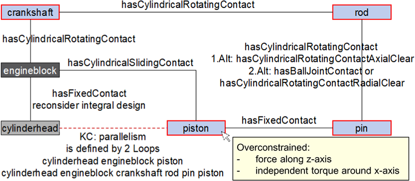
Figure 4. Results from loop detection as well as first mobility and constraint analysis with proposals for improved robustness in concept graph. While dark or light grey nodes represent the base part or rigid parts, blue nodes are generally movable, where a red outline indicates overconstraintness. Black edges represent assembly relations while red dashed edges represent key characteristics.
The loop detection is the basis for the mobility and constraint analysis using the screw theory described in Whitney (Reference Whitney2004), whereby all necessary information are already explicitly given in the concept graph. This analysis leads to individual statements about the movement options and the degree of constraints of single components of the concept with respect to the base part. The abstract results are automatically transferred into explicit information useful for the design engineer by providing method-specific knowledge. Depending on the relevance for the design engineer, these information are displayed visually in the graph or as text information in the metadata (e.g., for detailed constraint information); see Figure 4. This intended separation of information representation allows a quick overview of the essential information and enables the design engineer to understand the analysis results as well as the robust design proposals that are automatically generated.
These design proposals for the systematic improvement of the concept robustness are generated on the basis of the previous results and formalised design knowledge. Therefore, the negative correlation between overconstraintness and robustness (Matthiassen Reference Matthiassen1997) is utilised. With the aid of explicitly defined knowledge, a generally valid set of rules is created that proposes alternative assembly relations depending on the overconstraints, the initial assembly relation and its primary direction of motion (x, y or z). This guides the design engineer to the solution of the robustness problem. An overview of essential rules is shown in Table 1. For example, for the cylindrical rotating contacts of the analysed crank drive mechanism, a change to assembly relations with clearance is preferred; see Figure 4. Because of the abstraction in concept design, these rules are formulated in a generally valid way, considering functional production-related aspects. This often leads to several alternative proposals, which are prioritised here, taking into account design knowledge. Thus, for example, the production of a cylindrical rotating contact with axial clearance is easier than a ball joint.
Table 1. Rules for alternative proposals of assembly relations depending on the multiple limited force F or torque T

Note: ‘>’ signs indicate the hierarchy of the alternative proposals.
Abbreviations: BC, ball cylinder contact; BJ, ball joint; CR, cylindrical rotating contact; CRA, cylindrical rotating contact with axial clearance; CRAR, cylindrical rotating contact with axial/radial clearance; CRR, cylindrical rotating contact with radial clearance; CS, cylindrical sliding contact; PH, prismatic hinge contact; PHC, prismatic hinge contact with clearance.
The presented rules eliminate logical design mistakes during the revision of the concept without restricting the admissible design space. However, depending on the area of application and the industry-specific manufacturing conditions, the proposal alternatives can be further reduced, so that the design engineer’s decision-making scope is limited leading to a complete automation. Since such a restriction of the design space is not always feasible because of a lack of formalised knowledge, generally valid hints for concept redesign are generated in addition to these specific proposals. Unlike the usual handling of these hints (Matthiassen Reference Matthiassen1997; Ebro & Howard Reference Ebro and Howard2016), these notes are proposed as a function of the system structure, so that the design engineer is supported in the straightforward adaption of the concept. Thus, the following robust design hints are reduced to the relevant ones for the considered concept:
-
• apply clearance;
-
• use flexibility of parts;
-
• insert additional parts;
-
• replace sliding contact by rotating contact;
-
• combine parts with fixed contact in short loop.
Although a KC is best defined by only one loop, in practice, it is often determined by several loops with different lengths; also see Figure 4. Nevertheless, to realise the focus on one loop, the presented workflow intends to apply the previously mentioned hints for the reduction of the degree of constraint in the longer loops. For example, adding clearance in the longer loop of the crank drive largely reduces the tolerance problem to the short loop. This complies with the rule that it is easier to assure the KC via tolerances in the short loop than in the longer loops (Goetz, Schleich & Wartzack Reference Goetz, Schleich and Wartzack2018).
The adoption of the robust design proposals leads to a modified product concept. At the end of this iterative process with focus on kinematic robustness, the concept no longer contains any unintended overconstraints. As the comparison of the initial concept graph (Figure 3) and the resulting concept graph (Figure 5) shows, this state is achieved when one cylindrical rotating contact is replaced by a contact with axial and radial clearance. So, the displacement in z-direction as well as the rotation around the x-axis can be compensated in the crank drive mechanism; see Figure 3.

Figure 5. Resulting concept graph for crank drive. Modifications are highlighted in red text. Black edges represent assembly relations while red dashed edges represent key characteristics.
3.3. Tolerance-oriented concept design
According to the framework in Figure 2, this section comprises the transformation of the concept graph to geometry element level, the definition of tolerance loops, their tolerance-compliant adaption and the tolerance specification of the concept. The product knowledge ontology together with the tolerance knowledge ontology, which are described in Goetz & Schleich (Reference Goetz and Schleich2020) and summarised in the appendix, are the basis for this step.
The ongoing product development process requires further concretisation of the concept description leading to a transformation of the concept graph. Thus, with the aid of the knowledge from the product knowledge ontology, the concept graph at component level (Figure 5) is transformed into a concept description at geometry element level (Figure 6). Although this process is largely automated, some interaction by the design engineer is necessary, following the vision of a nearly unlimited design space and the avoidance of excessively strict specifications of the concept design. So, some components need a second reference orientation defined by the design engineer. Moreover, the break down to the geometry element level requires a redefinition of the assembly relations on geometry element level. For example, the cylindrical sliding contact between engine block and piston of a crank drive mechanism (Figure 5) is transferred to a contact between engine block cylinder and piston skirt in Figure 6. By taking into account the geometry element types and their orientation, this step is automated. However, since dimensional information are still missing in the concept design stage, this concretisation, for example, when contacting a component with several coaxial cylinders, is only possible with the implicit knowledge of the respective design engineer. By supporting with explicit basic knowledge, such as the compatibility of geometry elements in contact, the remaining options for the design engineer are reduced to a minimum and logical errors in the interaction can be avoided.

Figure 6. Geometry element graph with assembly and spatial relations of crank drive.
The result of this transformation step is a graph representing the interrelations of the main geometry elements of the concept. It is interactively linked with a simultaneously generated product ontology, which contains all the information of the specific concept known at this product development stage. Even though this step is fully associated with the concept design process and does not focus on aspects of robustness or tolerancing, it is a prerequisite for the subsequent steps considering variation.
Thus, it is the basis for the tolerance loop definition, which enables a first tolerance-compliant design at the concept level. The initial loop identification reveals the loops that contribute to a KC. With the help of the robustness improvements described in the previous section, these often multiple loops can be considered separately. So, the function-oriented tolerance specification is preferably limited to the short loop, because of the easier assurance of the function. The final choice of the loop, that is decisive for tolerancing, is up to the design engineer. Within this selected loop, full function-oriented tolerance specification is subsequently applied, while the elements outside this loop are only tolerated to ensure assemblability. For example, the KC ‘parallelism’ of the crank drive is determined by two loops with a length of 6, respectively, 13 elements, see Figure 6, whereby the shorter loop is selected as particularly relevant here.
In the sense of a robust design, the tolerancing effort and consequently the final tolerance costs are reduced by a computer-aided simplification of this selected loop. Therefore, formalised tolerancing knowledge is utilised comprising two different aspects. First, it is checked whether the loop can be shortened by deliberately swapping referenced and specified elements of spatial relations. The reason for this is that elements within the loop can be influenced by reference elements outside of the loop, which therefore have to be considered when assuring the KC. This scan takes into account that different reference geometry elements (e.g., line or plane) result in a different degree of restriction of the specified element. Moreover, the computer-aided approach checks whether sequential spatial relations within the loop can be combined or synthesised. For example, the perpendicular relation between ‘pistonSkirt’ and ‘pistonPinHole’ and between ‘pistonSkirt’ and ‘pistonCrown’ in Figure 6 could be replaced by a parallelism relation between ‘pistonCrown’ and ‘pistonPinHole’ enabling the elimination of the geometry element ‘pistonSkirt’ for the subsequent tolerance specification. For a generally valid statement when combining spatial relations of different kind, they were classified according to their predominance as follows: hasCoincidenceRelation – low; hasParallelRelation – medium; hasPerpendicularRelation – high. Thus, when combining different spatial relations, the one with the higher dominance is inserted as a new substitute relation. For example, the combination of a parallelism relation (between A and B) and a perpendicular relation (between B and C) results in a perpendicular relation between A and C.
Since this computer-aided simplification of the tolerance loop is part of the design concretisation in the context of the ongoing concept development, the automated modifications require confirmation by the design engineer. This allows an adaption of the concept design while taking tolerance aspects into account and demonstrates the close link between geometry and tolerance design. Consequently, to avoid iterations, this step defines the concept’s geometric relations by considering the formalised tolerance knowledge prior to the tolerancing process. Thus, at the end of this step, a tolerance-compliant geometric description of the product concept is available, which includes all information relevant for tolerance specification. This description is represented both in the form of an adapted geometry element graph for suitable visualisation and as a linked product ontology for further computer-aided processing.
The combination of this specific product ontology with the tolerance knowledge ontology described in the appendix leads to an individual tolerance ontology; see Figure 2. This ontology includes the relevant geometry- and assembly-related information as well as the tolerance knowledge, which is used for an automated tolerance specification of the concept. For a comprehensive description of this automated tolerancing, please refer to Goetz & Schleich (Reference Goetz and Schleich2020). In combination with the information from previous steps that are stored in the product ontology, a comprehensive tolerance specification is automatically carried out within this tolerance ontology ensuring functionality and assemblability of the concept design. Figure 7 exemplarily shows the resulting tolerance information for the piston crown.

Figure 7. Excerpt from ontology with tolerance specification proposals for piston crown.
Because of the automatic transfer of information from the preceding steps with respect to robust design, this tolerance specification is well integrated into the concept development and does not require any additional effort. The resulting tolerance ontology comprises functional, geometry and tolerance information and thus forms a sound basis for the subsequent product development steps. However, it is difficult for the design engineer to capture the relevant tolerance information at a glance because of the numerous textual information within the ontology editor; see Figure 7.
3.4. Visualisation and evaluation
Therefore, the last step of the proposed approach aims at a suitable visualisation of the results of the automated tolerance specification; see Figure 2. Previous studies have shown that graphs are beneficial for tolerance representation in early design stages, when the geometry of a product is not yet completely defined (Goetz, Schleich & Wartzack Reference Goetz, Schleich and Wartzack2018). These tolerance graphs enable a structured representation of relevant geometry elements, their assembly relations and tolerance information, and reveal the tolerance structure of the concept. Thus, the tolerance graph in Figure 8, that is automatically derived from the tolerance ontology, comprises all automatically generated tolerance information of a product concept, while supplementary tolerancing notes, which are relevant for the tolerance design process in the subsequent design stages, are stored in the metadata of the graph. Despite this separation of the visualisation levels, which is intended to ensure that the design engineer can focus on the relevant information, the graph quickly becomes complex; see Figure 8.

Figure 8. Extensive tolerance graph representing the results of the automated tolerance specification of the crank drive concept.
In accordance with the previously described selection of the short tolerance loop (also see Figures 4 and 6), the tolerance graph in Figure 8 essentially consists of one loop with a comprehensive tolerance specification of the elements involved. So, the KC is defined by the tolerances of the components cylinder head, engine block and piston. In addition, Figure 8 also contains some graph segments that are detached from each other, which represent components outside the selected loop but still require a tolerance specification to ensure assemblability, such as a clearance fit.
The final computer-aided visual synthesis of this graph taking tolerance knowledge into account leads to reduced complexity of the tolerance graph and thus increases its usability. This step eliminates the redundant and ambiguous information in the graph; see Figure 9. For example, the two edges ‘Straightness’ and ‘EnclosedStraightness’ cancel each other out. In addition, to ensure traceability, the information underlying the synthesis, such as enclosed tolerances, are stored in the metadata. Thus, the number of graphical tolerance information is reduced from 37 to 15 for the crank drive.

Figure 9. Reduced tolerance graph representing the synthesised results of the automated tolerance specification of the crank drive concept.
This representation of tolerance information from the ontology enables the design engineer to visually check the automatically defined tolerance specifications. Moreover, the number of tolerances involved in a KC or a concept is derived from the graph and thus allows an initial tolerance and robustness evaluation of the concept, as introduced in Goetz, Schleich & Wartzack (Reference Goetz, Schleich and Wartzack2018). Thus, the automated generation of the tolerance graph contributes to a quick comparison of tolerance specifications for different concept alternatives.
In summary, starting with an initial concept idea, a robust concept structure, a tolerance-oriented concept design and a detailed initial tolerance specification are available at the end of the proposed computer-aided approach summarised in Figure 2. The tolerance information thus already available in the concept stage and closely linked to the geometric design are a reliable basis for the tolerance design activities in the subsequent product development steps.
3.5. Implementation
To demonstrate the benefits and ensure comparable results in the subsequent user study, the proposed approach is prototypically implemented. Thus, the concept graph, which is the prerequisite for a computer-aided concept development, is first created with the graph editor yEd and stored as an Extensible Markup Language (XML)-structured file. The subsequent loop and kinematic analysis as well as the modification of the concept with respect to robustness is realised by a bidirectional coupling of yEd and MATLAB R2019a. The analysis results and suggestions for robustness improvement generated in the background with MATLAB are thus automatically transferred to the graph editor for a straightforward concept improvement. So, the user interaction is limited to the graph editor.
The fundamental product and tolerance knowledge ontology described in the appendix are set up in the open source software Protégé 5.5.0 which is widely used in research. MATLAB is used to unify the product information of this knowledge base with the information of the concept graph to automatically generate a geometry element graph and a corresponding specific product ontology; see Figure 2. In this step, the necessary input from the design engineer is provided via a MATLAB-internal user interface. Subsequently, this product ontology is imported into the compatible tolerance ontology in Protégé. This forms the basis for the automated tolerance specification utilising the Protégé internal reasoner Pellet and the Drools Engine for applying the tolerancing rules. The resulting, inferred tolerance ontology includes all relevant tolerance specification information. It is finally imported, interpreted and simplified by MATLAB to visualise the result of the ontology-based tolerance specification as a tolerance graph in yEd. This is the basis for a final robustness evaluation of the concept in MATLAB.
4. Discussion
The proposed approach enables the implementation of the robust design as well as the tolerance-compliant design and a first tolerance specification in the concept stage. It considers the interactions between robust design, respectively, tolerancing and the geometric product design. For extensive integration into the product development process, the individual modules of the approach are assigned to the key concretisation steps of the concept design stage (see Figure 1) enabling a simultaneous workflow. Thus, the approach actively shapes the geometric design of the concept, helps to avoid logical errors and adds value to the multicriteria concept evaluation by integrating the graph-based robustness evaluation, thus supporting the efficient concept selection.
The approach complements commercial computer-aided tolerancing software which focuses on quantitative tolerance analysis or semantic checks for tolerance specification considering only the geometry by providing a preceding step. Consequently, the approach is based on graphs instead of CAD models. In contrast to CAD models, these graphs enable simple handling during the tolerance loop detection and the implementation of design changes. Moreover, it is an appropriate representation of the little information available at the beginning of the concept stage, without the need for design assumptions. Although the design is already decisively predetermined by the CAD model and design changes, also with regard to the robust or tolerance-compliant design, are more difficult to implement, the idea of the approach can also be transferred to early CAD-based implementation, whereby the additional information in the 3D model would even bring some simplifications, for example, in the constraint analysis. However, since the approach aims at the earliest possible application, it is based on the evolving graphs.
To ensure a critical discussion, the approach was applied to further case studies and tested in an initial user study within the scope of this contribution. The different case studies, namely, coinage machine (Goetz, Schleich & Wartzack Reference Goetz, Schleich and Wartzack2018), car door hinge and window lifter mechanism (Goetz, Schleich & Wartzack Reference Goetz, Schleich and Wartzack2020) show the general applicability. Although the approach is useful for these examples and leads to a robustness improvement as well as to an appropriate tolerance specification of the concepts, its primary benefit from the multitude of considered aspects varies. For example, original designs, e.g., of window lifters, show more potential for robustness improvement compared to concepts such as the crank drive that is a derivative design. The subsequent transformation of the robust concept graph to geometry element level requires preparation in the form of formalised product design knowledge by experts; see Figure 2. Although this step is thus not an integral part of the designer’s activities in the workflow, the effort required to set up the associated ontology should be kept to a minimum. This is mainly achieved by the abstraction to the concept level, which ensures high reusability, especially in the industrial environment with a typically limited product range. Thus, the case studies showed that the knowledge required, for example, for the crank drive and the coinage machine, is largely identical and that the definition of standardised joining components in the sense of catalogues is useful with regard to reusability. The resulting graph utilising this ontology is the basis for the generation of reliable tolerance specification proposals that go far beyond the scope of existing approaches from the concept stage. However, since the geometry is not yet fully defined in the concept design, this specification cannot be comprehensive in terms of the detail design, so that dimensional tolerances are disregarded here and further tolerance information, such as necessary secondary and tertiary references, are only given as a textual hint. Thus, the proposed tolerance specification primarily supports the comparison and robustness evaluation of concepts as well as the detailed tolerance design in subsequent stages.
In summary, the approach supports the concept design of the studied examples in terms of robust and tolerance design. Although the case studies are simple and allowed to focus on one KC, the described methods can also be transferred to industrial and often more complex assemblies with numerous parts and KCs as well as multiple system states. Especially for concepts with many components, the advantages of automation as well as graph analysis mechanisms, such as tolerance loop analysis, become apparent. So, the approach enables a clear focus on the components relevant for robust and tolerance design. In the case of multiple KCs, these are preferably uncoupled during the initial complexity reduction, see Figure 2, which allows a separate consideration in the subsequent steps. A remaining coupling of the KCs would lead to a superposition of the respective robustness improvement and tolerance specification proposals. However, since these proposals are directly linked to the respective KCs, it enables a well-founded choice of options in case of conflicting hints, without disregarding aspects of a specific KC. Moreover, the number of KCs on the concept level is comparatively small or a division into separate subsystems and thus a separate consideration is possible. Similar to coupled KCs, multiple states in the present implementation lead to overlapping. However, this process can be improved by a linkage of the graph-based tolerance representation of concepts with approaches that capture these states in a structured way (Grauberger et al. Reference Grauberger, Goetz, Schleich, Gwosch, Matthisen and Wartzack2020).
Besides this theoretical discussion, the user study with seven participants from the field of mechanical engineering enables a comparison between the conventional, unsupported procedure and the proposed approach. The use of the crank drive with easily comprehensible functionality from the previous section ensures comparability of the participants’ results. The product knowledge ontology and the tolerance knowledge ontology including tolerancing rules, that are generally valid for most products from the mechanical engineering environment, are already given. Therefore, the users applied the approach summarised in Figure 2 starting from the crank drive concept sketch. The study showed that especially users without experience in graph-based product representation spent most of the processing time of the approach for the first setup of the concept graph, as shown in Figure 3. Thus, almost half of the total average duration of approximately 45 minutes for the entire approach including explanation, which is slightly below the average time required for the conventional procedure, was spent on this first step. Nevertheless, the structured information representation is a prerequisite for the computer-aided robust and tolerance design regardless of the product development stage. Although this concretisation is abstract especially in concept design, the user study confirmed that it is useful to avoid the anticipation of aspects of the final design and thus a premature fixation on details. Furthermore, despite the additional effort, the participants considered the graph representation and the resulting loop analysis surprisingly positive and quite useful even beyond the approach. Moreover, the users benefited from the local and specific robustness hints in the graph, which allow a straightforward adaptation of the concept for improved robustness. However, while experienced users primarily appreciate the automation of this step, especially for more complex assemblies where interrelations are unclear, less experienced users were partly surprised at the need to consider some of the proposed aspects. Thus, the approach contributes to an improved robustness of a product already during concept design. Although a quantification of this effect is not possible at this stage (Thornton, Donnelly & Ertan Reference Thornton, Donnelly and Ertan2000; Taguchi, Yano & Chowdhury Reference Taguchi, Yano and Chowdhury2005), the approach leads to a design that is increasingly consistent with established robust design principles of reduced complexity and kinematic robustness. In the subsequent tolerance-compliant concept adaptation as well as the tolerance specification, the participants of the user study agreed with the automatically generated proposals of the approach. Moreover, the comparison with the tolerance specification, manually created by the users, showed that the approach takes into account additional aspects and avoids syntax errors, especially among inexperienced users. On the other hand, experienced users primarily appreciate the automation and the avoidance of careless mistakes during tolerance specification.
5. Conclusion and outlook
Motivated by the discrepancy between the great potential and the lack of approaches, that support the design engineer in considering variation in the concept design stage without expert knowledge, an automated approach enabling a simultaneous concept and robust respectively tolerance design was proposed. Its distinctive key ideas are the intensive linkage of design and tolerance domain, the structuring of the concept design stage into individual steps for earliest possible integration and the computer-aided automation by utilising implemented product and tolerance knowledge helping to avoid extensive iteration loops.
On the basis of a concept graph, the robustness of the concept is first improved with specific redesign hints. This concept structure is automatically broken down to the level of the geometry elements enabling the tolerance-compliant concept design. Finally, the generated tolerance specification proposals allow a first evaluation of the tolerance design visualised in a tolerance graph. As the case studies as well as the results of the user study showed, the approach thus allows the design engineer to quickly obtain a robust concept design, provides a reliable basis for design decisions that come along with the progressive concretisation of the concept and supports the subsequent development process steps. In addition, the early integrated consideration of variation in concept design contributes to an increasing awareness of the effect of design decisions on robust and tolerance design.
However, further research should address the integration into the (industrial) product development process and further automation. Thus, an automated derivation of the concept graph based on a sketch would improve usability. Moreover, in the sense of consistency, an interface between the resulting tolerance graph and the CAD representation that is commonly used in the subsequent preliminary design is expedient. The degree of automation could be further increased by integrating additional information from the preceding steps in the product development process, such as functional requirements, and implementing industry-specific relations going beyond the proposed general rules. These ideas in combination with the consideration of multiple states according to Bjarklev (Reference Bjarklev2018) would lead to results that are even more comprehensive in a shorter time, further enhancing industrial relevance.
Acknowledgments
The authors thank the German Research Foundation (DFG) for supporting the research project ‘Integrated computer-automated tolerance management in early design stages’ under the grant numbers SCHL 2233/1-3 and WA 2913/17-3.
Competing Interest
The author(s) declare none.
Appendix A. Ontology knowledge base for tolerance-oriented concept design
The ontology knowledge representation, already fundamentally described in Goetz & Schleich (Reference Goetz and Schleich2020), is the basis for automated tolerancing of concepts and is summarised here for better traceability of the process described in the main section. Ontologies are suitable for this process because of the stringent mapping of logic. In the sense of the intended reuse of existing ontology structures (Noy & MCGuinness Reference Noy and MCGuinness2001), the terms within this knowledge base are widely adopted from other ontologies for automated tolerance specification, such as Zhong et al. (Reference Zhong, Qin, Huang, Lu, Gao and Du2013) and Qie et al. (Reference Qie, Qiao, Cui and Anwer2017). Since the formalised knowledge is used for both the detailing of the concept and the tolerance specification itself, two distinct but compatible ontologies, namely, product and tolerance knowledge ontology, are developed; see Figure 2.
A.1. Product knowledge ontology
The product knowledge ontology is the basis for the automated transition from the concept graph on component level to a detailed geometry element graph. Its classes, object and data properties are shown in Figure A1.

Figure A1. Classes, object and data properties of product knowledge ontology.
This structure allows a consistent ontological representation of assembly, geometry and tolerance-specific information of concepts. The limited scope of the product knowledge ontology contributes to a clear description. So, for example, the geometry definition is condensed to the essential geometry elements from the minimum geometric datum elements (MGDE) approach according to Desrochers & Clément (Reference Desrochers and Clément1994). Moreover, design knowledge is integrated in the property definition, so that logical mistakes in the definition of new concept components are avoided. For example, the definition of a cylindrical rotating contact includes that only one instance of the class ‘OuterCylindrical’ can be linked with one instance of the class ‘InnerCylindrical’. The additional definition of the level of detail of semantic product information (viz. ‘LevelDOF’, ‘LevelGeometry’ and ‘LevelTolerance’) for better reuse of concept information is a consistent extension of the approach presented in Goetz & Schleich (Reference Goetz and Schleich2020). This differentiation allows a combination of different components whose semantic information was defined at different levels of detail. While only the geometry elements and their orientation are defined for the components of the class ‘LevelDOF’, spatial relations are additionally defined in the class ‘LevelGeometry’. If, for example, the use of a specific supplier component is defined in the concept design, the tolerances are already defined here, and the component is classified in the corresponding class ‘LevelTolerance’. This allows a differentiated consideration of the different concept components defined in the ontology.
This universal applicable structure thus forms the framework for the unambiguous definition of various concept components. It is exemplarily shown for a pin respectively bolt in Figure A2. The generic definition of the geometry at this stage allows extensive reuse in many different applications.

Figure A2. Instances and their relations for a pin. The arrow colours indicate: red – hasRealFeatureSurface, light grey – hasDerivedFeature and black – hasPerpendicularRelation.
A.2. Tolerance knowledge ontology
The tolerance knowledge ontology is the basis for the automated tolerance specification of concepts. Because of the close linkage between product and tolerance design, the structure of the tolerance knowledge ontology is largely consistent with the product knowledge ontology; see Figure A3. However, additional information, such as enclosed or implicit tolerances, are included to meet the demand for a comprehensive, consistent tolerance specification that conforms to current standards, such as ASME Y14.5:2009 (2009) and ISO 1101:2017 (2017), and ensure traceability for the design engineer. For example, it facilitates to define whether a tolerance (e.g., straightness) is already enclosed by other specifications (e.g., flatness). This enables a more user-friendly visualisation of the tolerance specification results and leads to the proper documentation for the subsequent tolerancing activities. Furthermore, the numerous data properties allow to store additional functional relevant tolerancing information necessary for the detail design; see Figure A3.

Figure A3. Object and data properties of tolerance knowledge ontology.
This universal tolerance knowledge ontology does not contain any concept-specific product information. Instead, most of the necessary knowledge is mapped within the ontology using general Semantic Web Rule Language (SWRL) rules that extend the syntax of the OWL. Thus, these rules facilitate the assignment of tolerance information within the proposed framework. Aiming a comprehensive tolerance specification of the concept, the rules cover the following aspects and have been adapted and extended from established approaches (Goetz & Schleich Reference Goetz and Schleich2020):
-
• tolerances of form, orientation, position and run-out (Zhong et al. Reference Zhong, Qin, Huang, Lu, Gao and Du2013; Haghighi et al. Reference Haghighi, Mohan, Kalish, Vemulapalli, Shah and Davidson2015);
-
• tolerancing of surfaces in contact (Anselmetti et al. Reference Anselmetti, Chavanne, Yang and Anwer2010);
-
• tolerance zone modification (Anselmetti et al. Reference Anselmetti, Chavanne, Yang and Anwer2010);
-
• tolerance simplification (Britten Reference Britten1999; Jorden & Schütte Reference Jorden and Schütte2017).
Even though SWRL rules are a great option to enhance the ontological knowledge base, the application is limited by its special characteristics, like the monotonic behaviour (Horrocks et al. Reference Horrocks, Patel-Schneider, Boley, Tabet, Grosof and Dean2004). This means that already gained knowledge cannot be revoked, so that the sequential application of different rules can lead to conflicts. Thus, a top-down tolerancing following the listing above is crucial for a proper tolerance specification.
The following rule is an example of how the rules derived from existing approaches have been extended. Besides a roundness and cylindricity tolerance, a straightness tolerance for the derived axis is specified. In the final tolerance specification, this straightness and roundness tolerance is declared as enclosed in the cylindricity tolerance according to Britten (Reference Britten1999).
requiresGDTTolerancing(?x,?x) ^ InnerCylindrical(?x) ^ hasDerived-
Feature(?x,?y) -> hasStraightnessTolerance(?y,?y) ^ hasRoundness-
Tolerance(?x,?x) ^ hasCylindricityTolerance(?x, ?x)
Besides the extension of existing rules, the proposed precise tolerance specification requires the formalisation of implicitly used rules from previous work. Thus, for example, a line profile tolerance on a bore hole is automatically replaced by a roundness tolerance. Moreover, further knowledge that respects current standards and is primarily beneficial for the subsequent detailed tolerancing process is integrated in the tolerance knowledge ontology. For example, for a parallelism tolerance between two lines, the specification of a circular tolerance zone by using the tolerance zone prefix Ø is proposed.
In combination with the comprehensive set of rules, the tolerance knowledge ontology forms a proper, generally valid basis for an automated tolerance specification of concepts taking into account the demand for tolerance proposals, conformity to standards and traceability for the user. Thus, two compatible ontologies are available, which represent the generally valid tolerance knowledge on the one hand and the product-specific knowledge about the concept on the other hand.


 Open access