


1 Introduction
Significant advances in ultraintense and ultrashort laser technology have led numerous laboratories around the world to develop table-top PW-class laser systems as a means of investigating laser–matter interactions in relativistic regime[Reference Jeong and Lee1, Reference Danson, Haefner, Bromage, Butcher, Chanteloup, Chowdhury, Galvanauskas, Gizzi, Hein, Hillier, Hopps, Kato, Khazanov, Kodama, Korn, Li, Li, Limpert, Ma, Nam, Neely, Papadopoulos, Penman, Qian, Rocca, Shaykin, Siders, Spindloe, Szatmári, Trines, Zhu and Zuegel2]. The repetition rate of PW-class femtosecond lasers is an important issue for their practical applications. And the development of repetitive PW-class lasers has attracted a great attention in recent years. For example, in the United States, the BELLA PW laser working at 1 Hz and another 0.85 PW laser operating at 3.3 Hz were reported in 2017[Reference Nakamura, Mao, Gonsalves, Vincenti, Mittelberger, Daniels, Magana, Toth and Leemans3, Reference Wang, Wang, Rockwood, Luther, Hollinger, Curtis, Calvi, Menoni and Rocca4]. In Japan, the J-KAREN-P laser with PW-level peak power and 0.1 Hz repetition rate was reported in 2018[Reference Kiriyama, Pirozhkov, Nishiuchi, Fukuda, Ogura, Sagisaka, Miyasaka, Mori, Sakaki, Dover, Kondo, Koga, Esirkepov, Kando and Kondo5]. In South Korea, the  $1.5~\text{PW}/0.1~\text{Hz}$ laser and the $4.2~\text{PW}/0.1~\text{Hz}$ laser were reported in 2012 and 2017, respectively[Reference Yu, Lee, Sung, Yoon, Jeong and Lee6, Reference Sung, Lee, Yoo, Yoon, Lee, Yang, Son, Jang, Lee and Nam7]. In Europe, Amplitude and Thales also have commercial repetitive PW laser systems[8, 9]. Moreover, the scalability to higher peak power is another key issue for strong field physics in ultrarelativistic regime. The next-generation PW-class laser projects have already been proposed and constructed worldwide, which include Extreme Light Infrastructure, Apollon-10 PW laser, Vulcan-10 PW laser, and so on[Reference Danson, Haefner, Bromage, Butcher, Chanteloup, Chowdhury, Galvanauskas, Gizzi, Hein, Hillier, Hopps, Kato, Khazanov, Kodama, Korn, Li, Li, Limpert, Ma, Nam, Neely, Papadopoulos, Penman, Qian, Rocca, Shaykin, Siders, Spindloe, Szatmári, Trines, Zhu and Zuegel2, Reference Tiwari, Gaul, Martinez, Dyer, Gordon, Spinks, Toncian, Bowers, Jiao, Kupfer, Lisi, McCary, Roycroft, Yandow, Glenn, Donovan, Ditmire and Hegelich10]. In the near future, the focused laser intensity will probably exceed $10^{22}~\text{W}/\text{cm}^{2}$ and reach $10^{23}~\text{W}/\text{cm}^{2}$ based on the 10 PW-class lasers above. In China, although several PW-class lasers were reported by different laboratories, all of these lasers are working at single-shot mode[Reference Wang, Liu, Shen, Zhang, Teng and Wei11–Reference Zeng, Zhou, Zuo, Zhu, Su, Wang, Wang, Huang, Jiang, Jiang, Guo, Xie, Zhou, Wu, Mu, Peng and Jing13].
The Shanghai Superintense Ultrafast Laser Facility (SULF) is a large-scale scientific project located in Shanghai, China[Reference Cartlidge14–Reference Leng16]. The project was formally launched and funded in July 2016, which aims to generate the most powerful laser pulse with peak power up to 10 PW. In 2018, amplified pulse energy of 339 J from Ti:sapphire amplifiers was achieved in the 10 PW-class laser prototype, which can support a peak power of 10.3 PW with a compressed pulse duration of 21 fs[Reference Li, Gan, Yu, Wang, Liu, Guo, Xu, Xu, Hang, Xu, Wang, Huang, Cao, Yao, Zhang, Chen, Tang, Li, Liu, Li, He, Yin, Liang, Leng, Li and Xu17]. However, the 10 PW-class laser prototype can only operate at one shot every 3 h. Since then, great efforts have been devoted to the upgrade of the laser repetition rate. The SULF will finally consist of two laser beamlines, the SULF-10 PW beamline operating at one shot per minute and the SULF-1 PW beamline operating at 0.1 Hz repetition rate. The SULF will provide repetitive PW-level and 10 PW-level laser pulses for scientific researches on materials dynamics under extreme conditions, ultrafast sub-atomic physics and big molecule dynamics, and extreme-fast chemistry[Reference Leng16, Reference Hützen, Thomas, Böker, Engels, Gebel, Lehrach, Pukhov, Rakitzis, Sofikitis and Büscher18]. The layout of the SULF is illustrated in Figure 1.
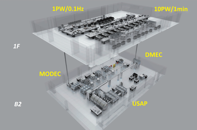
Figure 1. The layout of the SULF[Reference Leng15].
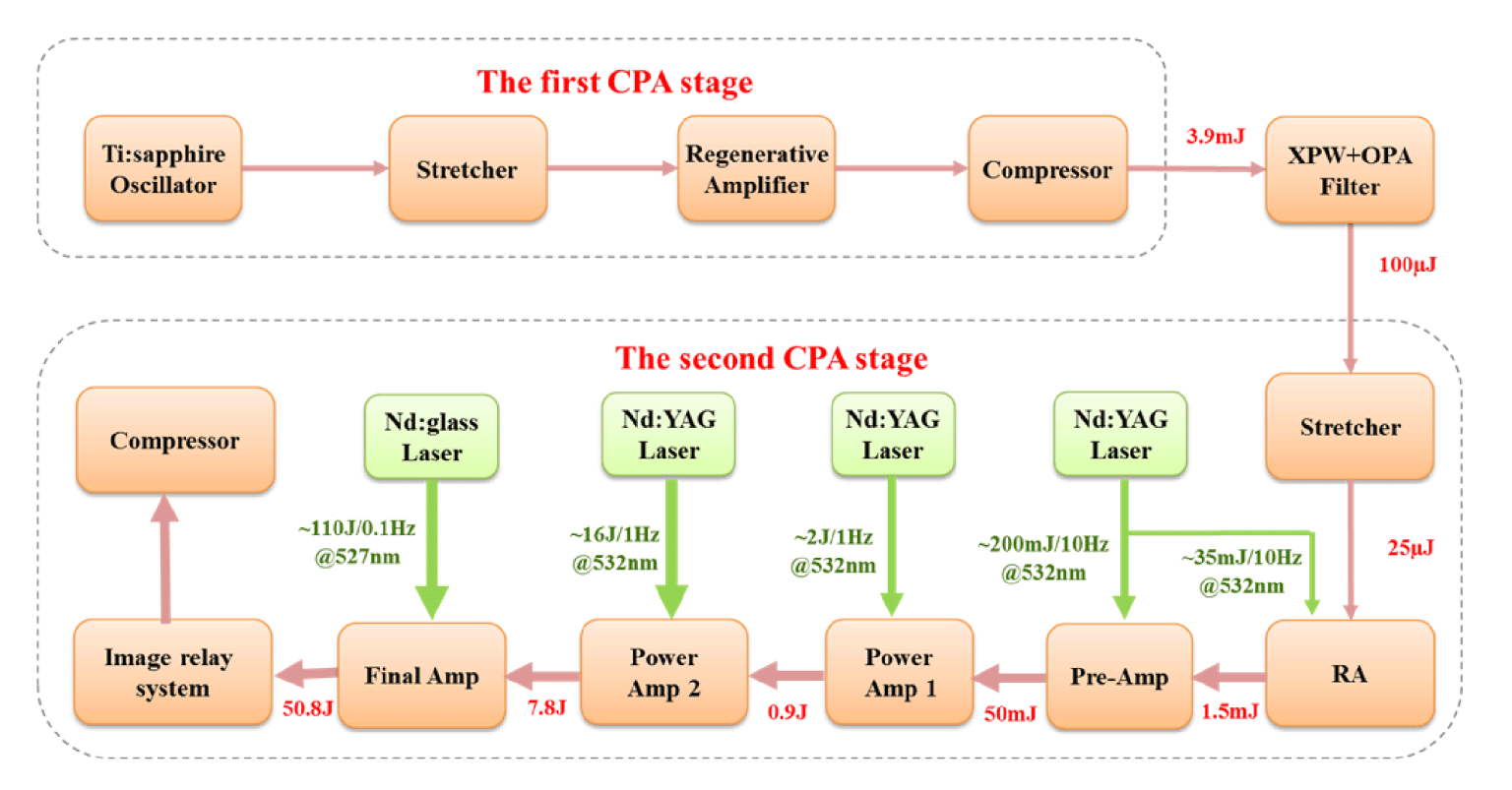
Figure 2. Schematic diagram of the SULF-1 PW beamline.
In this paper, the recent progress on the  $1~\text{PW}/0.1~\text{Hz}$ laser beamline of the SULF is reported. The SULF-1 PW laser beamline is based on the double chirped pulse amplification (CPA) scheme, which can generate laser pulses of 50.8 J at 0.1 Hz after the final amplifier; the shot-to-shot energy fluctuation of the amplified pulse is as low as 1.2% (std). After compression, a pulse duration of 29.6 fs is achieved, which can support a maximal peak power of 1 PW. The contrast ratio at $-80~\text{ps}$ before the main pulse is measured to be $2.5\times 10^{-11}$. The focused peak intensity is improved by optimization of the angular dispersion in the grating compressor. The horizontal and vertical angular pointing fluctuations in 1 h are measured to be $1.89~\unicode[STIX]{x03BC}\text{rad}$ (std) and $2.45~\unicode[STIX]{x03BC}\text{rad}$ (std), respectively. The moderate repetition rate and the good stability are the desirable characteristics for laser–matter interactions. The SULF-1 PW laser beamline is now commissioning, and preliminary experiments of particle acceleration and secondary radiation under 300–400 TW/0.1 Hz laser condition have been implemented. The progress on experiments and the daily stable operation of the laser demonstrate the availability of SULF-1 PW beamline.
2 Laser designs of the SULF-1 PW beamline
The SULF-1 PW beamline is a typical double-CPA system, which consists of two complete CPA stages linked by a nonlinear temporal filter. The schematic diagram of SULF-1 PW beamline is shown in Figure 2.
A commercial Ti:sapphire CPA laser (Coherent, Astrella) is used as the first CPA stage, which can deliver sub-40-fs pulses with 7 mJ energy at 1 kHz repetition rate. Initial seed pulses with energy of 3.9 mJ are injected into the temporal filter, which is based on the techniques of cross-polarized wave generation (XPWG) and femtosecond optical parametric amplification (OPA). This novel temporal filter mainly includes three parts: (1) a stage of XPWG, which can generate high-contrast and broadband seed pulses with several microjoule energy; (2) a stage of second harmonic generation (SHG) pump laser, which can provide pump laser with  ${\sim}400~\text{nm}$ central wavelength and ${\sim}1.75~\text{mJ}$ energy for femtosecond OPA; (3) a stage of femtosecond OPA, which can generate ultrahigh-contrast signal pulses and idler pulses with $100\text{-}\unicode[STIX]{x03BC}\text{J}$-level energy simultaneously. A detailed design of the nonlinear temporal filter is described in our previous work[Reference Yu, Xu, Liu, Li, Li, Liu, Li, Wu, Yang, Yang, Wang, Lu, Leng, Li and Xu19].
The second CPA stage consists of a stretcher, a regenerative amplifier (RA), a pre-amplifier, two power amplifiers, a final amplifier, an achromatic relay-imaging system and a grating compressor. Cleaned pulses from the temporal filter are temporally stretched to  ${\sim}700~\text{ps}$ (full-width at half-maximum (FWHM)) duration in the grating-based all-reflective Öffner stretcher. The transmission efficiency through the stretcher is 25%, which results in ${\sim}25~\unicode[STIX]{x03BC}\text{J}$ seed pulses for the RA. Before entering the RA, single pulse at 10 Hz repetition rate is selected by a Pockels cell (PC) assembly which consists of two high extinction ratio Glan laser polarizers and a KD*P PC. To save the cost, a common Nd:YAG laser (Quantel, CFR-400) at 10 Hz repetition rate is used to pump both the RA and the pre-amplifier. The RA is pumped at 38 mJ energy, and after about 10 round-trips, the seed pulses are amplified to 1.5 mJ energy. A spectral filter (Alpine Research Optics) is inserted into the RA, which can suppress gain narrowing and pre-compensate spectrum redshift in the following amplifiers[Reference Xu, Lu, Li, Wu, Li, Wang, Li, Lu, Liu, Leng, Li and Xu20, Reference Wu, Yu, Zhang, Li, Yang, Wu, Li, Wang, Liu, Lu, Xu and Leng21]. After passing through another two PC assemblies for suppression of nanosecond pre-pulse leaked from the RA, the repetition rate of the laser pulses decreases to 1 Hz. The 1 Hz pulses are expanded to 3 mm diameter and injected into the five-pass Pre-Amp, which is pumped at both sides with a total pump energy of 180 mJ and can amplify the pulse energy to 50 mJ. The output pulses of the Pre-Amp are expanded to 18 mm diameter and then introduced into a five-pass power amplifier (Power Amp 1), which is designed to produce 2 J of radiation under pump energy of 5 J. As suffered from optical damage, the output energy of Power Amp 1 is now reduced to 0.9 J for safety consideration. The output energy will be recovered once the spare parts are available. The 0.9 J laser pulses are then expanded to 35 mm diameter and injected into a three-pass power amplifier (Power Amp 2), which uses a water-cooled 60 mm diameter Ti:sapphire crystal that is pumped by four Nd:YAG lasers. Power Amp 2 is designed to produce 11 J of radiation under pump energy of 20 J and injected energy of 2 J. At present, the output energy of Power Amp 2 is controlled at 7.8 J under pump energy of 16 J and injected energy of 0.9 J. Both Power Amp 1 and Power Amp 2 work at 1 Hz repetition rate. In high-energy Ti:sapphire amplifiers with moderate repetition rate, the thermal lens effect can degrade the beam spatial quality and decrease the energy extraction efficiency. At present, the focal length of thermal lens in Power Amp 1 and Power Amp 2 is 410 and 194 m, respectively. Utilizing particularly designed beam expanders before the power amplifiers, specific expanding ratio and beam divergence are introduced to suppress the thermal lens effect[Reference Wu, Yu, Lu, Li, Xu and Leng22]. The output pulses of Power Amp 2 are expanded to 65 mm diameter and undergo further amplification in the three-pass final amplifier (Final Amp), which uses a large-aperture 100 mm diameter Ti:sapphire crystal that is pumped by four high-energy glass lasers (Amplitude Technologies, Constellation). Each frequency-doubled Nd:glass laser can provide a maximal output energy of ${\sim}30~\text{J}$ with two green (527 nm) beams at a repetition rate of 0.1 Hz. Image relay systems are implemented in order to magnify the pump beam size from 25 to ${\sim}70~\text{mm}$ on the Ti:sapphire crystal. In our design, the output energy from final amplifier is 60 J under a total pump energy of 120 J and an injected energy of 11 J. The transverse parasitic lasing is suppressed by using an index-matching fluid with absorbing dye and controlling the temporal delay between the seed pulses and the pump pulses[Reference Ple, Pittman, Jamelot and Chambaret23]. At present, average output energy of 50.8 J with 0.1 Hz repetition rate is achieved under a total pump energy of 110 J and an injected energy of 7.8 J. The total B-integral of the Ti:sapphire amplifiers is calculated to be 0.59.
An achromatic image relay system is designed and installed between the Final Amp and the grating compressor, which can expand the beam size from  ${\sim}65$ to ${\sim}213.5~\text{mm}$. The image relay system consists of two achromatic lenses with focal lengths of 5000 and 16,500 mm, respectively. A spatial filter will be installed at the focus of the two lenses in the near future, which can improve the spatial quality of the laser pulses and simultaneously prevent the scattered noise pulse from the amplifiers. It is worthy to note that an energy attenuation module (EAM) consisting of uncoated wedges, high reflective mirrors and a motorized linear translation stage is installed between the Final Amp and the image relay system, which is introduced for the measurement of laser parameters and the alignment of off-axis parabolic mirror (OAP) under a reasonable energy level[Reference Lu, Leng, Xu, Zhang, Li, Guo, Zou, Li and Wu24]. The surface quality of the optics in the EAM is carefully treated, which can keep the wavefront quality of the output pulses. Since the laser pulses before and after EAM share the same near-field and far-field monitoring systems, the pointing of direction of the laser pulses after the EAM is also guaranteed.

Figure 3. Schematic of the grating compressor with a vacuum chamber.
After the achromatic image relay system, laser pulses are transported from the ground floor to B2 floor by a large-aperture periscope. The grating compressor is installed on the B2 floor, which consists of a large-dimension vacuum chamber, two large-aperture mirrors and four gratings. As Figure 3 shows, the size of vacuum chamber is 4500 mm ( $L$)
$L$)  $\times \,1400~\text{mm}$ ( $W$)
$W$)  $\times 1000~\text{mm}$ ( $H$), the first and fourth gratings are brand new and their sizes are 265 mm ( $H$)
$H$)  $\times$ 420 mm ( $W$), and the second and third gratings are the old ones that have been used in our 10 PW-class laser prototype. Their size is 360 mm ( $H$)
$H$)  $\times \,565~\text{mm}$ ( $W$). The total transport efficiency of the achromatic image relay system, the large-aperture periscope and the grating compressor is only 58%, which is affected by the old gratings and the coating of the achromatic image relay system. Enhancement of the transport efficiency will be one of our future tasks. After compression, the pulse duration of 29.6 fs is achieved, which can support a maximal peak power of 1.0 PW at present.
3 Characteristics of the SULF-1 PW beamline
The output energy of the Final Amp is measured by an energy meter (Gentec-EO, QE95). Under pump energy of 110 J, the average output energy is 50.8 J which corresponds to an extraction efficiency of 39.1%. The low efficiency is probably caused by the energy loss in the 100 mm diameter Ti:sapphire crystal. Without the pumping, we have found that the incident seed energy decreases from 7.8 to 7.3 J after passing through the Ti:sapphire crystal once. It indicates that the single-pass energy loss of the large-aperture Ti:sapphire crystal is as large as 6.4%. The energy loss is caused by both the reflection of the end faces and the absorption of this large-aperture Ti:sapphire crystal. The Final Amp is operated near the saturation region and pumped by four Nd:glass lasers independently. A total of eight pump beams are delivered to the Ti:sapphire crystal, which can significantly reduce the effect of pump energy fluctuation by averaging. Then stable output energy can be obtained after the Final Amp. The measured energy fluctuation is about 1.2% (std) for 36 successive laser pulses, which is shown in Figure 4. Affected by the problem of optical damage, Power Amp 1 and Power Amp 2 are now still operated below the saturation region. The energy stability should be further improved after the full-load operation of both Power Amp 1 and Power Amp 2. The beam profile of the output laser after the Final Amp is also measured by a charge coupled device (CCD) (Spiricon, BeamGage), with a diameter of 2.6 mm, as shown in the inset of Figure 4.
The output laser has a near flat-top spatial profile. The inhomogeneity of the spatial profile is caused by the Nd:glass pump lasers, which are under in situ tests, and their near-field profiles are still under improvement.
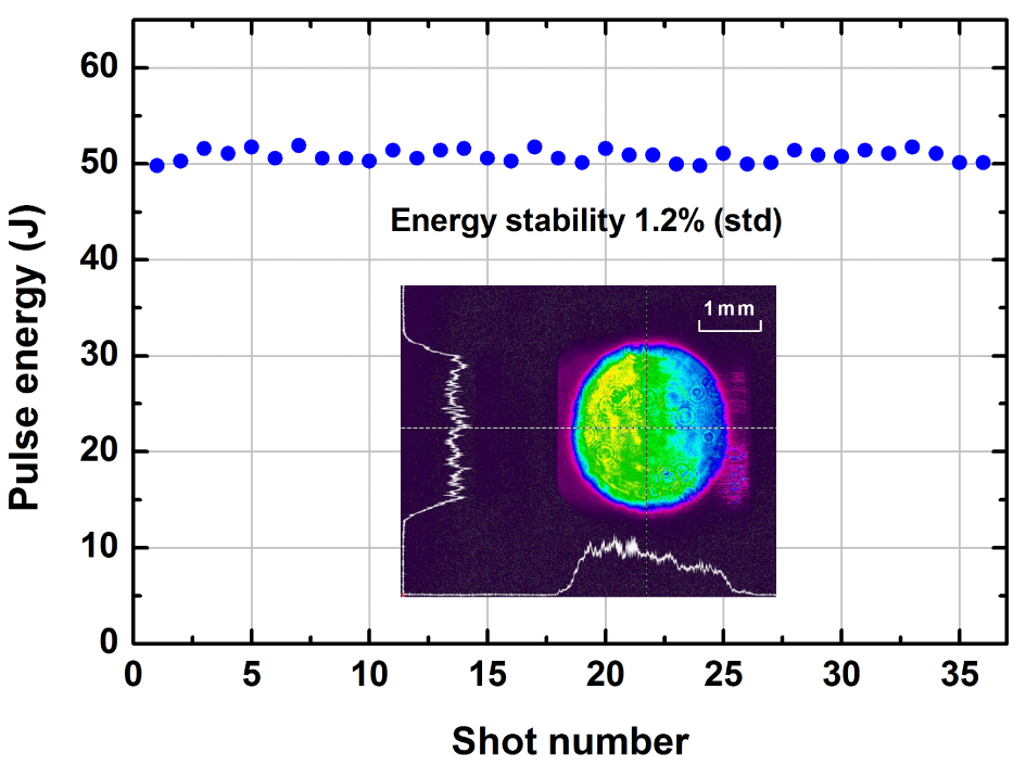
Figure 4. Shot-to-shot energy fluctuation of the amplified pulses. The inset shows the beam profile measured at the output of the Final Amp.
Gain narrowing and gain redshift are common problems in high-peak-power Ti:sapphire CPA lasers, which can narrow the spectrum and hence lengthen the compressed pulse duration[Reference Le Blanc, Curley and Salin25]. In the SULF-1 PW beamline, gain narrowing and redshift are suppressed by shaping the spectrum in the RA and controlling the gain in multi-pass amplifiers, which have been demonstrated to be effective methods for realizing broadband spectrum output[Reference Xu, Lu, Li, Wu, Li, Wang, Li, Lu, Liu, Leng, Li and Xu20, Reference Wu, Yu, Zhang, Li, Yang, Wu, Li, Wang, Liu, Lu, Xu and Leng21]. The evolution of the spectra in the amplifier chain is measured by a spectrometer (Ocean Optics, USB2000 $+$) and the results are shown in Figure 5. The measured spectral width of the output pulse from the Final Amp is about 58 nm at FWHM, which can support a Fourier-transform-limited (FTL) pulse duration of 22 fs.
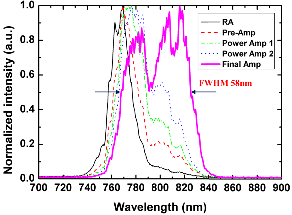
Figure 5. Measured spectra after the RA (black thin solid line), the Pre-Amp (red dashed line), the Power Amp 1 (green dot-dashed line), the Power Amp 2 (blue dotted line) and the Final Amp (magenta thick solid line).
Though the spectrum determines the FTL pulse duration, the actually achievable pulse duration is generally determined by the dispersion of the laser system. Before the measurement of pulse duration, the EAM is inserted between the Final Amp and the achromatic image relay system, which can decrease the energy of the pulses to be measured. The pulse duration is measured by a Wizzler (Fastlite). The typical pulse duration is 29.6 fs, which is shown in Figure 6. The residual high-order dispersion in the laser system is still a major limitation for the pulse compression. To compensate the residual high-order dispersion, an acousto-optic programmable dispersive filter (AOPDF) is being prepared, which can improve the compressed pulse duration and the temporal profile in the future. The B-integral of the laser system is about 0.59. Thus, the nonlinear phase contribution resulting from self-phase modulation is insignificant for pulse compression.
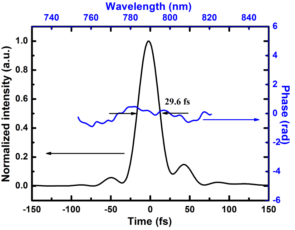
Figure 6. The duration and spectral phase of the compressed pulse.
To characterize the focused peak intensity of SULF-1 PW beamline, an OAP with 5655 mm focal length is used for the laser focusing and the study of laser wakefield acceleration (LWFA). The long focal length of the OAP is generally adopted in LWFA, which can be helpful for the self-guiding of the laser pulse and can stabilize the generation of the electron beams. Without pumping the Final Amp, the alignment of OAP and the measurement of the focal spot are done under  $120~\text{TW}/1~\text{Hz}$ laser condition. The EAM is used to control the energy of the 1 Hz laser pulse. By carefully controlling the surface quality of mirrors, the aberration of the beam expanders and the clamping stress of mechanical components, the wavefront distortion of the laser pulses can be significantly reduced. Since the residual wavefront distortion can be partially corrected by the OAP itself, the angular dispersion of the grating compressor becomes a main source for distortion of focal spot in SULF-1 PW beamline. Figure 7(a) shows the focal spot before the optimization of the grating compressor. The elongation and tilt of the focal spot are caused by the angular chirp of the grating compressor, which can be checked and improved by the method referred to in Ref. [Reference Liu, Liu, Wang, Ma, Liu, Zhang, Wang, Wang, Lin, Li, Chen, Wei and Zhang26]. Utilization of the OAP with a long focal length above will be helpful for the observation of the angular chirp. After carefully aligning the horizontal rotation and the groove tilt of the fourth grating, the focused beam quality is obviously improved. Figures 7(b) and 7(c) show the 2D and 3D images of the focal spot. The measured focal spot size is $33~\unicode[STIX]{x03BC}\text{m}\times 47~\unicode[STIX]{x03BC}\text{m}$ at FWHM, corresponding to 1.1 and 1.6 times of the diffraction limited value in the horizontal and vertical directions, respectively. The energy inside the diameter at FWHM is 33.7%. It demonstrates that the maximal focused peak intensity may reach $2.7\times 10^{19}~\text{W}/\text{cm}^{2}$ even with the $f/26.5~\text{OAP}$. A deformable mirror (DM), an $f/1.5~\text{OAP}$ and an objective lens are also in preparation. We aim to achieve ${\sim}10^{22}~\text{W}/\text{cm}^{2}$ intensity in the SULF-1 PW beamline in the near future.
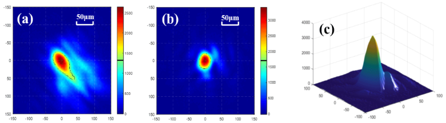
Figure 7. The focal spot measured in SULF-1 PW beamline (a) before and (b), (c) after optimization of the grating compressor by using  $f/26.5~\text{OAP}$.
Apart from the focused peak intensity, pulse temporal contrast is also of crucial importance, especially for laser–solid interactions. The temporal contrast is measured by a commercial third-order cross-correlator (Amplitude, Sequoia). Without pumping the Final Amp, the measurement is done under  $120~\text{TW}/1~\text{Hz}$ laser condition. The energy of the pulse to be measured is attenuated by the EAM. Figure 8 shows the contrast curve of SULF-1 PW beamline; the contrast ratio at $-80~\text{ps}$ before the main pulse is about $2.5\times 10^{-11}$, which is limited by the dynamic range of the measurement. Pre-pulses before the main pulse are generally attributed to artifacts, which are produced by multiple reflections of the optical components in the amplifiers and the measurement setup. However, as real pre-pulses can also be generated by nonlinear coupling between the main pulse and the post-pulses[Reference Didenko, Konyashchenko, Lutsenko and Tenyakov27], a detailed investigation of pre-pulses and post-pulses is still necessary in our future work. In addition, plasma mirrors are also designed and planned to be used after the compressor to improve the temporal contrast further.
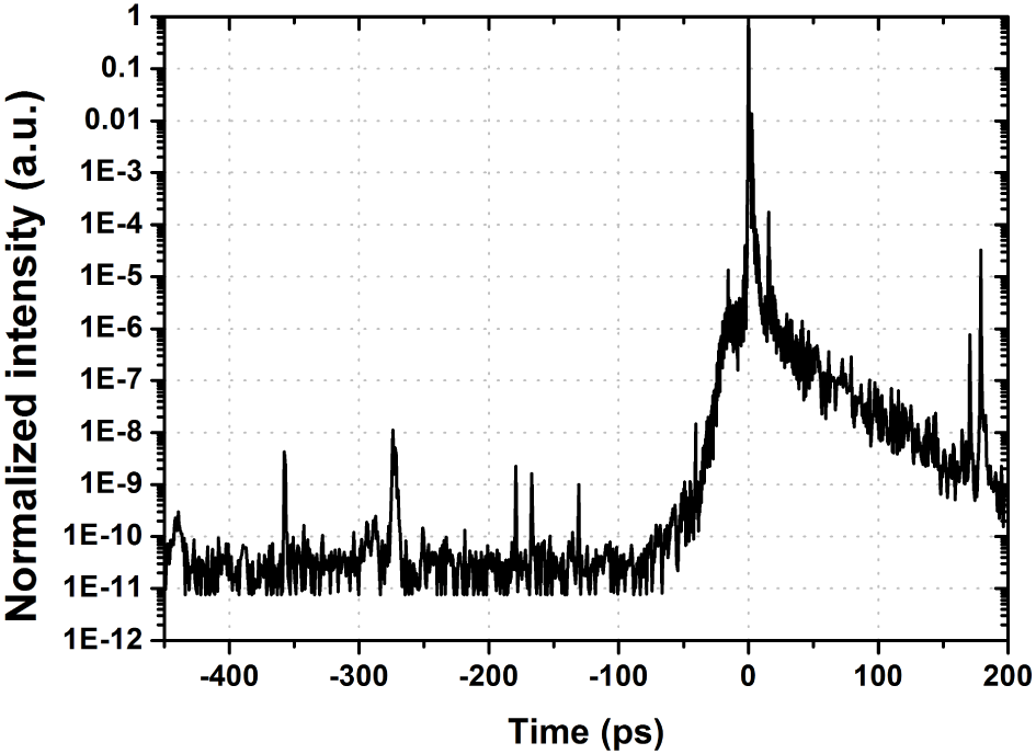
Figure 8. Temporal contrast of the compressed pulses.
Last but not least, the laser pointing stability is also crucially important for laser–matter interaction, especially for investigations requiring repeatability and reproducibility. Laser pointing fluctuation generally results from thermal drift, random vibration and air turbulence. The temperature of the laboratory is kept at 22  $\pm$ 0.5 $\,^{\circ }\text{C}$ and power supplies of the laser are located in an isolated room, which reduce the effect of thermal drift. The building of the SULF is carefully designed and the vibration of the floor is controlled below $0.5~\unicode[STIX]{x03BC}\text{m}$ at 1–100 Hz.
Moreover, the laser beam path is covered to avoid air turbulence. Apart from the passive methods above, a beam stabilization system (New Focus, GuideStar) is also used after the Pre-Amp to further improve the pointing stability. After the compressor, the pointing stability is measured under  $120~\text{TW}/1~\text{Hz}$ condition. Figure 9 shows the laser pointing fluctuation in 1 h. The horizontal and vertical angular pointing fluctuations are measured to be 1.89 and $2.45~\unicode[STIX]{x03BC}\text{rad}$ (std), respectively. The excellent stability is a desirable characteristic for laser–matter interactions.
4 Commissioning of SULF-1 PW beamline
The SULF-1 PW laser beamline is now in the phase of commissioning, and the long-term reliability of the laser system will be checked by carefully increasing the pulse peak power, which can reduce the risk of optical damage. Meanwhile, preliminary applications on particle acceleration and secondary radiation have been implemented based on the SULF-1 PW beamline.
First, an experiment on LWFA was done under  ${\sim}300~\text{TW}/0.1~\text{Hz}$ laser condition. 300 MeV quasi-monoenergetic electrons are repetitively produced with on-target laser intensity of ${\sim}8\times 10^{18}~\text{W}/\text{cm}^{2}$. Moreover, high-brightness gamma rays could be observed based on reverse Compton scattering. Further experiments of LWFA aimed at ${\sim}10~\text{GeV}$ electrons are in design and preparation. Second, experiment on proton acceleration was carried out under ${\sim}400~\text{TW}/0.1~\text{Hz}$ laser condition. Limited by the pre-pulses, Al target with a thickness of $10~\unicode[STIX]{x03BC}\text{m}$ is adopted in the experiment. The maximum proton energy of 14 MeV was obtained with on-target laser intensity of ${\sim}5\times 10^{20}~\text{W}/\text{cm}^{2}$. Nanometer target will be tested after the elimination of the pre-pulses.
After daily operation under  $300{-}400~\text{TW}/0.1~\text{Hz}$ laser condition, the laser system has not suffered obvious optical damage yet. The progress on the experiments and the daily stable operation of the laser demonstrate the availability of the SULF-1 PW beamline. Pulse peak power will be gradually increased for test in the next step. The future works will be focused on the improvement of the pulse spatial–temporal quality.
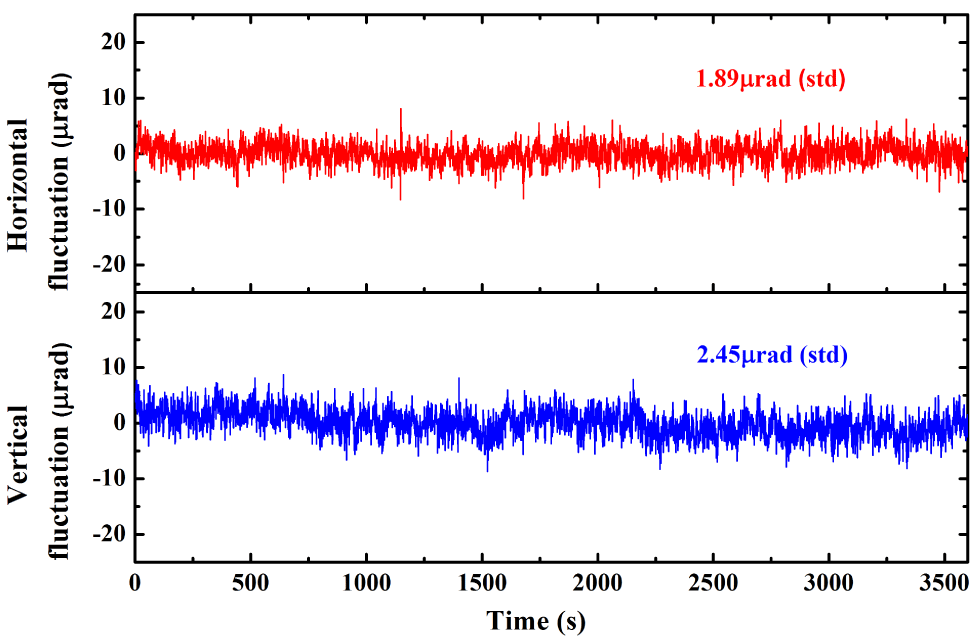
Figure 9. Beam pointing stability measured after the compressor.
5 Conclusions
In conclusion, basic features of the  $1~\text{PW}/0.1~\text{Hz}$ laser beamline in SULF are presented. The SULF-1 PW beamline is based on double-CPA scheme, which can generate 50 J energy at 0.1 Hz repetition rate after the final amplifier. The typical compressed pulse duration is about 29.6 fs, which can support a maximal peak power of 1 PW. The temporal contrast was enhanced by implementing the novel temporal filter combining XPWG technique and femtosecond OPA technique. The focused peak intensity was improved by optimization of the angular dispersion in the grating compressor. The measured energy fluctuation is as low as 1.2% (std), and the pointing stability in 1 h is around $2~\unicode[STIX]{x03BC}\text{rad}$ (std). The moderate repetition rate and the good stability are desirable characteristics for laser–matter interactions. The following works will be focused on the improvement of pulse spatial–temporal quality. By utilization of AOPDF and DM, pulse duration and focal spot issues will be improved in the near future.
Acknowledgements
The authors acknowledge the support from the electron-acceleration team led by Wentao Wang, Rong Qi and the proton-acceleration team led by Hui Zhang. This work was supported by the National Natural Science Foundation of China (Nos. 11127901, 61521093 and 61505234), International S&T Cooperation Program of China (No. 2016YFE 0119300), Strategic Priority Research Program of the Chinese Academy of Sciences (No. XDB160301), Technology Commission of Shanghai Municipality (No. 2017SHZDZX02) and Youth Innovation Promotion Association of the Chinese Academy of Sciences.


 Open access