


1 Introduction
New phenomena have emerged as laser intensity has increased. Ultrashort ultra-intense lasers have been rapidly developed based on the chirped pulse amplification (CPA)[ Reference Strickland and Mourou 1 ] technique and the subsequent development of the optical parametric chirped pulse amplification (OPCPA)[ Reference Dubietis, Jonušauskas and Piskarskas 2 ] technique. The peak power density of ultrashort ultra-intense lasers is increasing and has exceeded 1021 W/cm2[ Reference Li, Qin, Zhang, Li, Fan, Wang, Xu, Wang, Yu, Xu, Liu, Wang, Wang, Zhang, Liu, Bai, Gan, Zhang, Wang, Fan, Sun, Tang, Yao, Liang, Leng, Shen, Ji, Li and Xu 3 ], which is higher than the traditionally considered relativistic intensity (1018 W/cm2) by three orders of magnitude. The laser intensity will be increased further with the advancement of the next-generation petawatt (PW) class laser project[ Reference Lureau, Laux, Casagrande, Chalus, Pellegrina, Matras, Radier, Rey, Ricaud, Herriot, Jougla, Charbonneau, Duvochelle and Simon-Boisson 4 – Reference Bashinov, Gonoskov, Kim, Mourou and Sergeev 8 ], which will provide an entirely new arena and direction for related research and open up new research directions. At present, there are several sets of PW-class ultrashort ultra-intense laser facilities, such as Vulcan[ Reference Danson, Brummitt, Clarke, Collier, Fell, Frackiewicz, Hancock, Hawkes, Hernandez-Gomez, Holligan, Hutchinson, Kidd, Lester, Musgrave, Neely, Neville, Norreys, Pepler, Reason, Shaikh, Winstone, Wyatt and Wyborn 9 ], PHELIX[ Reference Bagnoud, Aurand, Blazevic, Borneis, Bruske, Ecker, Eisenbarth, Fils, Frank, Gaul, Goette, Haefner, Hahn, Harres, Heuck, Hochhaus, Hoffmann, Javorková, Kluge, Kuehl, Kunzer, Kreutz, Merz-Mantwill, Neumayer, Onkels, Reemts, Rosmej, Roth, Stoehlker, Tauschwitz, Zielbauer, Zimmer and Witte 10 ], Omega-EP[ Reference Zuegel, Bahk, Bromage, Dorrer, Earley, Kessler, Kruschwitz, Morse, Maywar, Oliver, Qiao, Right, Schmid, Shoup, Waxer and Kelly 11 ], NIF-ARC[ Reference Di Nicola, Yang, Boley, Crane, Heebner, Spinka, Arnold, Barty, Bowers, Budge, Christensen, Dawson, Erbert, Feigenbaum, Guss, Haefner, Hermann, Homoelle, Jarboe, Lawson, Lowe-Webb, McCandless, McHale, Pelz, Pham, Prantil, Rehak, Rever, Rushford, Sacks, Shaw, Smauley, Smith, Speck, Tietbohl, Wegner and Widmayer 12 ], PETAL[ Reference Raffestin, Lecherbourg, Lantuéjoul, Vauzour, Masson-Laborde, Davoine, Blanchot, Dubois, Vaisseau, d’Humières, Gremillet, Duval, Reverdin, Rosse, Boutoux, Ducret, Rousseaux, Tikhonchuk and Batani 13 ], LFEX[ Reference Shiraga, Fujioka, Nakai, Watari, Nakamura, Arikawa, Hosoda, Nagai, Koga and Kikuchi 14 ], SG-II Peta-watt (SG-II PW)[ Reference Zhu, Zhu, Li, Zhu, Ma, Lu, Fan, Liu, Zhou, Xu, Zhang, Xie, Yang, Wang, Ouyang, Wang, Li, Yang, Fan, Sun, Liu, Liu, Zhang, Tao, Sun, Zhu, Wang, Jiao, Ren, Liu, Jiao, Huang and Lin 15 ] and others, that have provided the opportunity to conduct research on various topics, such as particle acceleration sources[ Reference Daido, Nishiuchi and Pirozhkov 16 – Reference Pomerantz, McCary, Meadows, Arefiev, Bernstein, Chester, Cortez, Donovan, Dyer, Gaul, Hamilton, Kuk, Lestrade, Wang, Ditmire and Hegelich 19 ], X-ray/γ-ray radiation sources[ Reference Powers, Ghebregziabher, Golovin, Liu, Chen, Banerjee, Zhang and Umstadter 20 , Reference Liang 21 ], plasma diagnostics[ Reference Daido, Nishiuchi and Pirozhkov 16 , Reference Lancia, Albertazzi, Boniface, Grisollet, Riquier, Chaland, Le Thanh, Mellor, Antici, Buffechoux, Chen, Doria, Nakatsutsumi, Peth, Swantusch, Stardubtsev, Palumbo, Borghesi, Willi, Pépin and Fuchs 22 – Reference Zhao, An, Xie, Lei, Yao, Yuan, Xiong, Wang, Ye, Xie, Fang, Lei, Pei, He, Zhou, Wang, Zhu and Qiao 24 ], fast ignition[ Reference Roth, Cowan, Key, Hatchett, Brown, Fountain, Johnson, Pennington, Snavely, Wilks, Yasuike, Ruhl, Pegoraro, Bulanov, Campbell, Perry and Powell 25 , Reference Kodama, Norreys, Mima, Dangor, Evans, Fujita, Kitagawa, Krushelnick, Miyakoshi, Miyanaga, Norimatsu, Rose, Shozaki, Shigemori, Sunahara, Tampo, Tanaka, Toyama, Yamanaka and Zepf 26 ], cancer therapy[ Reference Bulanov and Khoroshkov 27 ], warm dense matter[ Reference Morea, Yonedab, Morikami and Quant 28 ] and other experimental studies.
The SG-II PW laser facility was constructed in 2016 with the output capability of a kJ single-pulse picosecond laser, which can form a combined ps- and ns-driven laser-integrated experimental platform together with the SG-II upgrade facility. This satisfies the demand for relevant physical experiments in high-power laser conditions in multiple fields. Thousands of physical experiments have been performed with satisfactory performance[ Reference Zhu, Zhu, Li, Zhu, Ma, Lu, Fan, Liu, Zhou, Xu, Zhang, Xie, Yang, Wang, Ouyang, Wang, Li, Yang, Fan, Sun, Liu, Liu, Zhang, Tao, Sun, Zhu, Wang, Jiao, Ren, Liu, Jiao, Huang and Lin 15 ]. Recently, the SG-II PW facility has undergone extensive maintenance and comprehensive technical upgrades in terms of the seed source, contrast and focal focus. A systematic test analysis showed that the quality of the ps laser improved significantly after maintenance; however, the overall performance was not clear.
When the laser intensity reaches relativistic levels (I ≥ 1018 W/cm2), it can produce an ultra-strong accelerating gradient electric field up to 106 times that of conventional pedals, which can be used for proton acceleration to accelerate proton energy to levels higher than MeV. In 2000, Snavely et al. [ Reference Snavely, Key, Hatchett, Cowan, Roth, Phillips, Stoyer, Henry, Sangster, Singh, Wilks, MacKinnon, Offenberger, Pennington, Yasuike, Langdon, Lasinski, Johnson, Perry and Campbell 29 ] demonstrated a laser-driven proton acceleration (LDPA) experiment to produce protons of the order of tens of MeV with an ultrashort, ultra-intense laser that illuminated a solid target. Since then, research on LDPA has gained extensive attention, and different acceleration mechanisms, such as target normal sheath acceleration (TNSA)[ Reference Wilks, Langdon, Cowan, Roth, Singh, Hatchett, Key, Pennington, MacKinnon and Snavely 30 ], radiation pressure acceleration (RPA)[ Reference Henig, Steinke, Schnürer, Sokollik, Hörlein, Kiefer, Jung, Schreiber, Hegelich, Yan, Meyer-ter-Vehn, Tajima, Nickles, Sandner and Habs 31 ], collisionless shock wave acceleration (CSA)[ Reference Silva, Marti, Davies, Fonseca, Ren, Tsung and Moria 32 , Reference Haberberger, Tochitsky, Fiuza, Gong, Fonseca, Silva, Moria and Joshi 33 ], Coulomb explosion acceleration (CE)[ Reference Ditmire, Tisch, Springate, Mason, Hay, Smith, Marangos and Hutchinson 34 ], breakout afterburner acceleration (BOA)[ Reference Yin, Albright, Hegelich and Fernández 35 ] and magnetic vortex acceleration (MVA)[ Reference Nakamura, Bulanov, Esirkepov and Kando 36 ], have been gradually developed. Among these acceleration mechanisms, the TNSA mechanism was proposed first and is currently the most extensively used. The physical image of the TNSA mechanism is relatively clear and concise. The ultrashort ultra-intense incident laser is absorbed on the front surface of a solid film target, and the electrons are heated and propagate to the posterior part of the target to establish an ultra-intense sheath electric field. The electric field directly ionizes the hydrogen in the water vapor adsorbed on the posterior surface of the target and accelerates the hydrogen ions. Hydrogen ions (i.e., protons) are accelerated and emitted in a direction normal to the posterior of the target. Numerous theoretical simulations and experiments have confirmed the correlation between the proton cutoff energy and laser parameters in the TNSA mechanism[ Reference Petrov, McGuffey, Thomas, Krushelnick and Beg 17 , Reference Krushelnick, Clark, Beg, Dangor, Najmudin, Norreys, Wei and Zepf 37 – Reference Kaluza, Schreiber, Santala, Tsakiris, Eidmann, Meyer-ter-Vehn and Witte 39 ]; for example, the maximum proton cutoff energy that can be achieved in the TNSA mechanism is usually proportional to the half-power of the driving laser intensity[ Reference Krushelnick, Clark, Beg, Dangor, Najmudin, Norreys, Wei and Zepf 37 ]. The conditions of ultrashort, ultra-intense laser facilities directly determine the proton beam characteristics of the TNSA generation. This also makes the LDPA experiment based on the TNSA mechanism a reference indicator for testing the comprehensive driving capability of ultrashort, ultra-intense laser facilities[ Reference Burdonov, Fazzini, Lelasseux, Albrecht, Antici, Ayoul, Beluze, Cavanna, Ceccotti, Chabanis, Chaleil, Chen, Chen, Consoli, Cuciuc, Davoine, Delaneau, d’Humières, Dubois, Evrard, Filippov, Freneaux, Forestier-Colleoni, Gremillet, Horny, Lancia, Lecherbourg, Lebas, Leblanc, Ma, Martin, Negoita, Paillard, Papadopoulos, Perez, Pikuz, Qi, Quéré, Ranc, Söderström, Scisciò, Sun, Vallières, Wang, Yao, Mathieu, Audebert and Fuchs 40 ]. Higher cutoff energies and more stable proton outputs signify better conditions for the laser facility.
Therefore, in this study, experiments on LDPA based on the TNSA mechanism were conducted at the maintained SG-II PW laser facility. The results showed that the generated high-energy proton beams had substantially higher cutoff energies. Furthermore, a high-energy proton beam with a maximum cutoff energy of more than 70 MeV was obtained using the double-membrane target structure, which is very close to the results reported in the current literature for obtaining the highest cutoff energy based on the TNSA mechanism. These results demonstrate that the comprehensive driving capability of the maintained SG-II PW facility has improved significantly and reached a first-class level worldwide. The SG-II PW facility will provide higher-quality laser conditions for additional physical experiments in the future.
2 Performance enhancements of the SG-II PW facility
2.1 Introduction to the SG-II PW facility
The SG-II PW facility was constructed by the National Laboratory of High Power Laser and Physics and adopted the OPCPA+CPA technology route; its optical path is shown in Figure 1. The front-end of the facility adopted a cascaded OPCPA scheme and injected chirped pulses from the parametric amplification of the pulse generation system into the amplification chain of the SG-II ps PW laser system. The amplifier consists of a rod amplifier and a slab amplifier in the main oscillator-power amplifier (MOPA) scheme. The compressor included four large-aperture 1740 lines/mm gratings. The dimensions of the gratings are 1025 mm × 350 mm. The near-field diameter of the beam is approximately 310 mm. The facility achieved single-pulse output of 1 kJ/1.7 ps at 1ω (λ = 1.053 μm) after compression in 2016. The facility can provide experiments at near-PW standards with power densities of up to 1020 W/cm2 (or higher)[ Reference Zhu, Zhu, Li, Zhu, Ma, Lu, Fan, Liu, Zhou, Xu, Zhang, Xie, Yang, Wang, Ouyang, Wang, Li, Yang, Fan, Sun, Liu, Liu, Zhang, Tao, Sun, Zhu, Wang, Jiao, Ren, Liu, Jiao, Huang and Lin 15 ], but most experiments are usually conducted at slightly lower conditions, typically at 300 J/1 ps or 500 J/10 ps at 1ω, by taking into account the component lifetime and other factors[ Reference Ding, Ouyang, Zhang, Jiang, Hou, Jiang, Tao, Zhu, Liu, Zhu and Zhu 41 ].

Figure 1 Schematic of the optical path of the SG-II PW laser facility.
The SG-II PW facility has been in operation for several years. With the increase in the operating time in recent years, optical components have gradually developed aging, bad spots and contamination, which have imposed device maintenance requirements, while new technologies have gradually been developed to improve the performance of laser facilities. Therefore, the SG-II PW facility has recently undergone comprehensive maintenance and optimization. Optimization consists of two main aspects. One is the signal-to-noise ratio of the front-end pulse generation system and the other is the terminal focusing capability.
2.2 Significant improvement in the front-end signal-to-noise ratio
The optimization of the laser signal-to-noise ratio is divided into two main parts: one for the suppression of parametric fluorescence and the other for the elimination of prepulses.
The suppression of parametric fluorescence is achieved by increasing the energy of the seed source from nanojoules to millijoules by increasing the picosecond OPA, which achieves high-gain amplification in the picosecond time-domain window, effectively suppressing the parametric fluorescence in the ns time-domain window and ultimately increasing the front-end signal-to-noise ratio from 107 to values of more than 1011[ Reference Xiao, Pan, Jiang, Wang, Du, Guo, Huang, Lu, Cui, Yang, Wei, Wang, Xiao, Li, Wang, Ouyang, Fan, Li and Zhu 42 ].
The prepulse is mainly from the (secondary) reflected light from the rear surface of the reflective or transmissive element. This light spectrally modulates the main pulse. The compression causes the backpulse to be transferred to the prepulse owing to the nonlinear B-integral effect[ Reference Bromage, Dorrer and Jungquist 43 ]. The elimination of prepulses was mainly achieved by optimizing the key optical components in the ns-OPCPA assembly.
Figure 2 shows the waveform of the optimized OPCPA front-end at the output energy of 50 mJ and the compressed pulse width of 400 fs. All prepulses were eliminated, and the signal-to-noise ratio was significantly improved compared with previous methods.

Figure 2 Comparison of the signal-to-noise ratio of the front-end optical parametric chirped pulse amplification (OPCPA) output of the picosecond pulse before and after optimization.
2.3 Optimization of the terminal focusing capability
The terminal focusing capability is directly related to the power density on the target surface and is a key factor in the use of ultrashort ultra-intense lasers for physics experiments. The measurement accuracy of the focal spot was improved by optimizing the key parameters of the deformation mirror, thus establishing a focal spot and wavefront measurement system at the center of the target chamber, and performing full-field measurement and control. The terminal focusing capability of the system was improved by using adaptive optics to measure and correct the aberrations of the full optical path system combined with precise control of the off-axis parabolic mirror attitude. The optical focal spot, which includes 50% of the laser energy, was enhanced from four to two times the diffraction limit, and its size was significantly reduced.
Figure 3 shows X-ray images from a laser-irradiated metal film target measured with a grazing incidence pinhole camera designed for ultra-strong laser–plasma experiments in the working band of 0.5–2.5 keV[
Reference Wang, An, Xiong, Fang, Wang, Zhang, Hua, Sun and Wang
44
]. Compared with conventional pinhole cameras[
Reference Theobald, Sorce, Donaldson, Epstein, Keck, Kellogg, Kessler, Kwiatkowski, Marshall, Sampat, Seka, Shah, Shvydky, Stoeckl, Waxer and Regan
45
], grazing incidence can effectively suppress the noise of hard X-rays produced by laser-irradiated targets in ultrahigh power density conditions, thus obtaining a relatively realistic X-ray image at the focal spot location. Figure 3 shows that the size of the X-ray image is significantly reduced after the terminal focusing optimization with the full-width-at-half-maximum value dropping from approximately 50 μm to approximately 25 μm. This indicates a reduction in the actual laser focal spot. This value is already very close to the size of the adjustment optical focal spot of $\varPhi $
20 μm[
Reference Ding, Ouyang, Zhang, Jiang, Hou, Jiang, Tao, Zhu, Liu, Zhu and Zhu
41
,
Reference Ouyang, Cui, Zhu, Zhu and Zhu
46
].
$\varPhi $
20 μm[
Reference Ding, Ouyang, Zhang, Jiang, Hou, Jiang, Tao, Zhu, Liu, Zhu and Zhu
41
,
Reference Ouyang, Cui, Zhu, Zhu and Zhu
46
].

Figure 3 X-ray images and scanned intensity curve of the laser irradiating metal planar target: (a) image before optimization; (b) image after optimization; (c) scanned intensity curve along the x-direction.
3 Studies of laser-driven proton acceleration based on target normal sheath acceleration
3.1 LDPA scheme with the SG-II PW facility
Based on the maintained SG-II PW facility, an LDPA experiment with a ps laser based on the TNSA mechanism was conducted, and the scheme is shown in Figure 4(a). Figure 4(b) shows an actual photograph of the target chamber. A single beam of a picosecond laser (wavelength 1053 nm, pulse duration 1–10 ps, energy 100–500 J) output from the SG-II PW laser facility was focused on the target surface with P-polarization and an incidence angle of 21° through an off-axis parabolic mirror with a focal length of 800 mm. The F# value of the optical path was approximately 2.5. The target was a Cu or an Au planar thin film with a thickness of approximately 20 μm, which is sufficiently thick for LDPA with a picosecond laser as the driving source, thus ensuring that the accelerated generated proton source is mainly derived from the TNSA mechanism.

Figure 4 Light path and diagnostic arrangement of a laser-driven proton acceleration (LDPA) experiment based on the target normal sheath acceleration (TNSA) mechanism. (a) Schematic of the arrangement. (b) Photograph of the target chamber.
The main diagnostic method used to measure proton signals is a multilayer stack of radiochromic films (RCFs)[ Reference Borghesi, Schiavi, Campbell, Haines, Willi, MacKinnon, Gizzi, Galimberti, Clarke and Ruhl 47 ], which are placed in the normal direction to the target back, and the front surface is approximately 40 mm from the target back surface. RCFs are an internationally common measurement method for LDPA that has been used for many years and performed well in previous LDPA experiments. The RCF model used in the experiments was HD-V2 manufactured by Gafchromic, USA[ Reference Chen, Gauthier, Bazalova-Carter, Bolanos, Glenzer, Riquier, Revet, Antici, Morabito, Propp, Starodubstev and Fuchs 48 ], with a dose-response range of 10–1000 Gy and a thickness of 105 μm, including a plastic substrate thickness of 97 μm and a sensitive layer thickness of 8 μm. The layer is very sensitive to proton signals and less sensitive to X-rays and electron signals[ Reference Hey, Key, Mackinnon, MacPhee, Patel, Freeman, Van Woerkom and Castaneda 49 ]; therefore, it can be used for high-energy proton beam measurements. Al films of appropriate thickness were placed between each RCF layer. These Al films can attenuate the energies of high-energy protons, thus allowing the recording of higher-energy proton signals with fewer RCFs. Subsequently, the minimum proton energy required to reach each RCF layer can be calculated using Monte Carlo codes to determine the proton energy deposition in the material. The maximum cutoff energy of the proton beam can be determined according to the position of the last RCF where the proton signal is recorded.
In addition, a grazing incidence pinhole camera designed for ultrahigh intensity laser–plasma experiments was placed in a direction of 10° with respect to the normal of the target surface in front of the target to monitor the focal spot condition of the incident laser-irradiated target where the pinhole size is approximately $\varPhi $
10 μm, the distance from the pinhole to the target is 85 mm and the magnification is approximately 7.7. Two sets of electron magnetic spectrometers (EMSs) were placed in the direction of 30° with respect to the normal of the target surface in front of the target and 50° with respect to the normal of the target surface at the back of the target to measure the energy spectrum of the outgoing hot electrons. The parameters of the two EMS sets were identical. The induction intensity was 0.3 T, the incident collimation hole diameter was 1 mm, the distance from the target surface was 500 mm and the measured spectrum range was 0.2–260 MeV[
Reference Xiong, An, Wang, Zhang, Jiao, Lei, Wang, Hu, Wang and Sun
50
,
Reference Li, An, Hu, Xiong, Lei, Xie, Wang, Wang, Zhang and Huang
51
].
$\varPhi $
10 μm, the distance from the pinhole to the target is 85 mm and the magnification is approximately 7.7. Two sets of electron magnetic spectrometers (EMSs) were placed in the direction of 30° with respect to the normal of the target surface in front of the target and 50° with respect to the normal of the target surface at the back of the target to measure the energy spectrum of the outgoing hot electrons. The parameters of the two EMS sets were identical. The induction intensity was 0.3 T, the incident collimation hole diameter was 1 mm, the distance from the target surface was 500 mm and the measured spectrum range was 0.2–260 MeV[
Reference Xiong, An, Wang, Zhang, Jiao, Lei, Wang, Hu, Wang and Sun
50
,
Reference Li, An, Hu, Xiong, Lei, Xie, Wang, Wang, Zhang and Huang
51
].
3.2 Experimental results
Typical results of the LDPA experiments with the picosecond laser at the maintained SG-II PW facility are shown in Figure 5. The pulse duration of the driving laser was approximately 1 ps, the energy of the target was approximately 280 J and the focal spot size was approximately $\varPhi $
25 μm. So, the power density on the target surface was approximately 5 × 10¹⁹ W/cm2. The target was a planar thin film of Au with a thickness of approximately 20 μm.
$\varPhi $
25 μm. So, the power density on the target surface was approximately 5 × 10¹⁹ W/cm2. The target was a planar thin film of Au with a thickness of approximately 20 μm.

Figure 5 Several images of different layers of radiochromic film (RCF) sheets showing proton signals with different proton energies.
The scanned images of the six RCF sheets are shown in Figure 5, and the sheet numbers 5th, 13th, 20th, 25th, 26th and 27th are the numbers in the upper right corner of each sheet. As the number of RCF sheets increases, protons must be transported through the additional layers of RCF sheets and Al films to reach the RCF at the corresponding position. The proton energy corresponding to each RCF layer in the experiment was calculated using the Monte Carlo code SRIM-2013-Pro[ Reference Ziegler, Ziegler and Biersack 52 , 53 ], depending on the thickness of the RCF sheets (the material is plastic and the thickness is the thickness of each layer multiplied by the number of layers penetrated) and the thickness of the Al films (accumulated according to the thickness of the passing Al films). This energy was also the minimum proton energy that can cause the darkening of the RCF layer. The six RCF sheets in Figure 5 correspond to the minimum proton energies of 12.9, 38.3, 49.8, 57.9, 59.6 and 61.4 MeV, respectively. It is clear from Figure 5 that the last RCF sheet in which the proton signal can be clearly distinguished is the 26th layer, whereas the proton signal in the 27th layer is indistinguishable. This indicates that the initial energy of the generated protons exceeds 59.6 MeV, which can darken the 26th layer RCF but does not reach 61.4 MeV, that is, it cannot darken the 27th layer RCF.
The direction normal to the posterior part of the target (0°, labeled in white +) and the direction of the laser propagation (21°, marked in blue +) are also shown in Figure 5. The proton signal propagates along the target-back normal direction and the signal intensity distribution gradually decreases as the number of RCF layers or the proton energy increases; these are typical findings related to the TNSA mechanism, thus indicating that the measured LDPA signal is derived from the TNSA mechanism[ Reference Simpson, Scott, Mariscal, Rusby, King, Grace, Aghedo, Pagano, Sinclair, Armstrong, Manuel, Haid, Flippo, Winslow, Gatu-Johnson, Frenje, Neely, Kerr, Williams, Andrews, Cauble, Charron, Costa, Fischer, Maricle, Stuart, Albert, Lemos, Mackinnon, MacPhee, Pak and Ma 54 , Reference Margarone, Kim, Psikal, Kaufman, Mocek, Choi, Stolcova, Proska, Choukourov, Melnichuk, Klimo, Limpouch, Sung, Lee, Korn and Jeong 55 ]. It is noteworthy that a weaker darkening spot can still be observed in the middle part of the 27th RCF sheet, and also in the 26th and further layers thereafter. Its intensity and size did not change significantly; thus, this corresponds to the background noise caused by high-energy electrons in the target-back normal direction[ Reference Wagner, Deppert, Brabetz, Fiala, Kleinschmidt, Poth, Schanz, Tebartz, Zielbauer, Roth, Stöhlker and Bagnoud 56 ].
3.3 Higher cutoff energy proton using a double-film target
In the experiments described above, the cutoff energy of the proton beam was close to 60 MeV, which is much better than the results of the LDPA experiments conducted in the SG-II PW facility before maintenance, fully demonstrating the effect of recent maintenance and technology upgrades. Therefore, an attempt was made to obtain a proton beam output with a higher cutoff energy using a double-film target.
The double-film target included two thin films; however, its structure and principles were completely different from those of the double-layer target of the transmission plasma mirror[ Reference Wei, Yuan, Fang, Ge, Ge, Yang, Li, Liao, Zhang, Liu, Chen, Zhao, Zhuo, Li, Sheng and Zhang 57 , Reference Huang, Albright, Yin, Wu, Bowers, Hegelich and Fernández 58 ], as shown in Figure 6. Figure 6(a) shows the structure of a double-layer target based on a plasma mirror, and Figure 6(b) shows the double-film target. In Figure 6(a), the laser is focused on the surface of the T2 target, and the T1 target acts as a plasma mirror to absorb the prepulse and improve the contrast of the laser focused on the T2 target, which in turn enhances the quality of the accelerated proton beam. In Figure 6(b), the laser is focused on the surface of the T1 target and forms a target-back electric field E. The T2 target is located at a certain position, and is induced by the action of the target-back electric field E to generate an additional electric field E’, which in turn may induce a re-acceleration effect. This configuration was first proposed by Braenzel et al. [ Reference Braenzel, Andreev, Abicht, Ehrentraut, Platonov and Schnürer 59 ] based on the relativistic transparency mechanism, and the possibility of a double-film structure to enhance the quality of proton beams was theoretically illustrated.

Figure 6 Two different double target structures. (a) Double-layer target for a plasma mirror. (b) Double-film target for sheath field modulation.
A preliminary numerical simulation of the double-film target was performed using the particle in cell (PIC) code named EPOCH. The simulated conditions are as follows: laser wavelength = 1053 nm, pulse duration = 0.4 ps, power density = 1 × 10¹⁹ W/cm2, focal spot size = $\varPhi $
14.3 μm, incidence angle = 21°, T1 target thickness = 20 μm, T2 target thickness = 0.3 μm; material: Au and double-film spacing d = 250 μm. Figure 7 shows the 2D numerical simulation results for the spatial distribution of the electric field for the two target types at two moments (500T
0 and 700T
0). Figures 7(a) and 7(b) show the results for a single target, that is, there is only the T1 target, whereas Figures 7(c) and 7(d) show the results for the double-film target. Conversely, Figures 7(a) and 7(c) are the results at 500T
0, and Figures 7(b) and 7(d) depict the results at 700T
0. It is obvious that an induced electric field is generated at the position of the T2 target back at the moment 700T
0 owing to the addition of the very thin target T2. This new electric field potentially re-accelerates the protons, thus causing a boost in proton beam energy.
$\varPhi $
14.3 μm, incidence angle = 21°, T1 target thickness = 20 μm, T2 target thickness = 0.3 μm; material: Au and double-film spacing d = 250 μm. Figure 7 shows the 2D numerical simulation results for the spatial distribution of the electric field for the two target types at two moments (500T
0 and 700T
0). Figures 7(a) and 7(b) show the results for a single target, that is, there is only the T1 target, whereas Figures 7(c) and 7(d) show the results for the double-film target. Conversely, Figures 7(a) and 7(c) are the results at 500T
0, and Figures 7(b) and 7(d) depict the results at 700T
0. It is obvious that an induced electric field is generated at the position of the T2 target back at the moment 700T
0 owing to the addition of the very thin target T2. This new electric field potentially re-accelerates the protons, thus causing a boost in proton beam energy.

Figure 7 Two-dimensional spatial distribution of electric field intensity for ps laser-driven single- and double-film targets. (a), (b) Single target and (c), (d) double-film target; (a), (c) at 500T 0 and (b), (d) at 700T 0.
The same scheme and laser conditions as those in Figure 5 were used for the experiments, except that the target was changed to a double-film target. The pulse duration of the driving laser was approximately 1 ps, the energy of the target was approximately 300 J and the focal spot size was approximately $\varPhi $
25 μm. The target was a planar thin film of Au with a thickness of approximately 20 μm. T1 in the double-film target is the same as that in the single target, that is, the thickness of the Au planar film is approximately 20 μm, the T2 target has an Au planar film thickness of 0.3 μm and the double-film spacing d, which is related to the driving laser conditions and to other factors, may be a key parameter. The results for d = 830 μm are shown in Figure 8. Similar to Figure 5, six images of RCF sheets are given for the 5th, 13th, 20th, 31st, 32nd and 33rd layers, and the minimum proton energies corresponding to each RCF layer were 12.9, 38.3, 49.8, 68.2, 70.0 and 71.4 MeV, respectively.
$\varPhi $
25 μm. The target was a planar thin film of Au with a thickness of approximately 20 μm. T1 in the double-film target is the same as that in the single target, that is, the thickness of the Au planar film is approximately 20 μm, the T2 target has an Au planar film thickness of 0.3 μm and the double-film spacing d, which is related to the driving laser conditions and to other factors, may be a key parameter. The results for d = 830 μm are shown in Figure 8. Similar to Figure 5, six images of RCF sheets are given for the 5th, 13th, 20th, 31st, 32nd and 33rd layers, and the minimum proton energies corresponding to each RCF layer were 12.9, 38.3, 49.8, 68.2, 70.0 and 71.4 MeV, respectively.

Figure 8 Several images of different layers of RCF sheets showing the proton beam output with higher cutoff energy using a double-film target.
It is clear from Figure 8 that the last RCF sheet in which the proton signal can be clearly distinguished is the 32nd layer, whereas the proton signal in the 33rd layer is already indistinguishable. This indicates that the initial energy of the generated protons exceeds 70.0 MeV, but does not reach 71.4 MeV. This is the first time that a proton beam with a cutoff energy higher than 70 MeV has been obtained at the SG-II PW laser facility.
4 Discussion
4.1 Performance improvement of the SG-II PW facility
LDPA using the SG-II PW facility has been conducted for many years, and a variety of experiments for proton applications have also been conducted; however, the highest cutoff energies of proton sources are generally not high. Figure 9 shows the proton cutoff energy data obtained from LDPA experiments using the driving laser with a 1 ps pulse duration over the years corresponding to the actual drive laser energy range of 115–374 J. It can be observed that the proton cutoff energy does not change significantly with increases in the drive laser energy by 2–3 times, thus remaining in the range of 20–30 MeV. Figure 9 shows the recent results after the maintenance of the SG-II PW laser facility. The driving laser energy corresponds to approximately 280 J, but the cutoff energy of the proton beam yields significant increases, reaching 50–60 MeV; this change is equivalent to an improvement that is almost equal to two times. In other words, increasing the energy of the driving laser alone is not sufficient to produce a proton beam with a higher cutoff energy; thus, improving the comprehensive performance of the driving laser is the key factor. The results demonstrate that the capability of the SG-II PW laser facility was significantly improved.
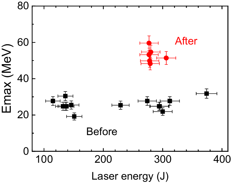
Figure 9 Maximum proton cutoff energy at different laser energies before and after maintenance.
4.2 Double-film target for higher cutoff energy
The original intention of the double-film target design was to modify the target backsheath electric field by adding a layer of film at an appropriate location after the main target. As shown in Figure 7, the additional film layer excited a new electric field E’ subject to the action of the electric field E behind the main target, which in turn caused a change in the overall sheath electric field. However, it is difficult to understand whether this change causes an increase in the cutoff energy of the accelerated protons. From the perspective of energy conservation, the new electric field was excited by the original electric field. Thus, the original electric field was inevitably attenuated; this resulted in a weakened total electric field. This was completely different from conventional cascade LDPA[ Reference Andreev, Nickles and Platonov 60 ], where the second electric field was generated with a second laser-driven film target, so the total effect of the two electric fields is increased. This was also confirmed by Chen et al. [ Reference Chen, Robinson, Antici, Brambrink, d’Humières, Gaillard, Grismayer, Mancic, Mora, Romagnani, Audebert, Pépin and Fuchs 61 ], who used a double-film target for LDPA experiments, which affected the quality of the proton beam but with lower cutoff energy.
Some of these traces are shown in Figure 7. Figures 7(b) and 7(d) show the electric field intensity distributions of the single- and double-film targets at the moment of 700T 0, respectively. However, as shown in Figure 7(d), a new electric field is generated at distances of more than 250 μm, and the electric field of the main target is reduced. This is clearly demonstrated in Figure 10, which shows the electric field intensity profile obtained from the scan at position y = 0 in Figures 7(b) and 7(d). In the case of the double-film target, the electric field intensity decreased substantially before 250 μm despite the formation of a new electric field at 250 μm. However, a proton beam output with a higher cutoff energy was clearly obtained in the experiment using the double-film target, and the increase was more than 15%, thus indicating that there are unclear physical mechanisms that need to be investigated further.

Figure 10 Electric field intensity distribution versus position for ps laser-driven single target and double-film target conditions. The data are from Figures 7(b) and 7(d). The blue line is for a single target and the red line is for a double-film target.
In addition to the aforementioned conditions of a double-film spacing of 830 μm, experiments with other double-film spacings were also conducted. Consequently, in most of the laser shots, the proton cutoff energy does not increase compared with that of a single target and even decreases in certain conditions, which is consistent with the phenomenon in the literature[ Reference Huang, Albright, Yin, Wu, Bowers, Hegelich and Fernández 58 ]. When the spacing is small, the T2 target may destroy the effective accelerating electric field on the posterior part of the main target T1; when the spacing is larger, the effects on the T2 target by the electric field of T1 are minor. Therefore, the proton cutoff energy was comparable to or reduced by a single thin-film target. It is only possible to obtain protons with a higher cutoff energy when the spacing is suitable and certain special conditions are met. However, it is not currently clear which specific conditions are required.
5 Conclusion
The SG-II PW laser facility has undergone extensive maintenance and technology upgrades, and its overall performance has improved. An LDPA experiment based on the TNSA mechanism was conducted to evaluate the driving performance of the ps laser in the maintained SG-II PW facility. The experimental results showed that the cutoff energy of the accelerated high-energy proton beam significantly improved to approximately 60 MeV, which is approximately twice that of previously obtained results. Accordingly, a double-film target structure whose physical mechanism is not yet well understood was used to obtain a high-energy proton beam output with a maximum cutoff energy of up to 70 MeV. These results demonstrate that the comprehensive performance of the ps laser beam of the SG-II PW laser facility was improved significantly, thus providing a better experimental platform for future research.
Acknowledgement
The authors acknowledge the staff of the SG-II PW laser facility for their assistance with the execution of this work. This work was funded by the National Natural Science Foundation of China (Grant No. 12075227), the National Natural Science Foundation of China - NSAF (Grant No. U2130121), the National Key Research and Development Program of China (Grant No. 2016YFA0401102) and the Science Challenge Project (Grant No. TZ2018005).


 Open access