


1 Introduction
The Mamyshev oscillator (MO), a novel passive mode-locking technique, is frequently employed as an alternative to conventional mode-locked lasers due to its ultra-high modulation depth and exceptional performance in pulse generation[ Reference Li, Gao, Ma, Wu, Huo, Han, Wageh, AI-Hartomy, AI-Sehemi, Liu and Zhang 1 ]. Typically, the MO is composed of end-to-end Mamyshev regenerators. In addition, the mode-locking mechanism relies on spectral broadening induced by self-phase modulation (SPM) and offset spectral filtering. When the pulse in the MO attains sufficient peak power, the spectral broadening induced by SPM effectively bridges the spectral gap between the two filters[ Reference Haig, Sidorenko, Thorne and Wise 2 ]. With multiple round-trips in the cavity, the pulse is continuously amplified and narrowed. This process results in an intensity-dependent saturable absorber effect. Consequently, this mechanism theoretically enables the MO to attain a 100% modulation depth, providing a natural advantage in generating high average power and short pulse duration[ Reference Rochette, Chen, Sun and Hernandez-Cordero 3 – Reference Zheng, Yang, Lau, Zhu and Li 5 ]. To date, researchers have made significant progress in MOs, including energy enhancement, pulse shortening, power scaling and other aspects, by utilizing various cavity configurations[ Reference Boulanger, Olivier, Morasse, Trépanier, Bernier and Piché 6 – Reference Nie, Wang and Huang 11 ]. However, the ultra-high modulation depth also restricts the generation of a high repetition rate[ Reference Želudevičius, Mickus and Regelskis 12 ]. It is noteworthy that gigahertz (GHz) repetition rates in MOs have not been extensively investigated.
Therefore, how to generate pulses with a GHz repetition rate has become a worthwhile research focus in MOs. Over the past few decades, two primary methods have been utilized to attain GHz repetition rates. One convenient approach involves shortening the laser cavity length to increase the fundamental frequency[ Reference McFerran, Nenadović, Swann, Schlager and Newbury 13 – Reference Zhu, Yang, Liu, Li, Sun, Fang, Chen, Chen and Feng 17 ]. Another solution is harmonic mode-locking (HML)[ Reference Sobon, Sotor and Abramski 18 – Reference Ling, Huang, Zou, Xing, Yan, Zhao, Zhou, Zhang and Mou 21 ], in which the laser operates at a multiple of its fundamental frequency. For MOs, reducing the cavity length to enhance the fundamental frequency presents significant challenges due to its structural configuration, which typically results in a long cavity length. This inherently structural characteristic limits the ability to achieve high repetition rates. Thus, the most effective approach to obtain a high repetition rate in MOs is through HML. Under this method, in 2020, Poeydebat et al. [ Reference Poeydebat, Scol, Vanvincq, Bouwmans and Hugonnot 22 ] reported the first high-order HML pulse in an MO with a repetition rate of 107.8 MHz. Then, in 2021, higher HML was achieved with a tunable range of repetition rate from 16 to 305 MHz[ Reference Piechal, Szczepanek, Karda’s and Stepanenko 23 ]. In 2024, Sui et al. [ Reference Sui, Jin, Liu, Zhang and Xu 24 ] achieved 89th-order HML, corresponding to a repetition rate of 395.2 MHz. However, GHz repetition rates in MOs have neither been experimentally demonstrated nor extensively explored in the literature. This phenomenon can be attributed to the ultra-high modulation depth inherent in MOs, which hinders pulse splitting[ Reference Želudevičius, Mickus and Regelskis 12 , Reference Sui, Jin, Liu, Zhang and Xu 24 ]. To attain higher-order HML, it is essential to increase the pump power. However, as the pump power increases, the stability of the mode-locking process tends to decrease.
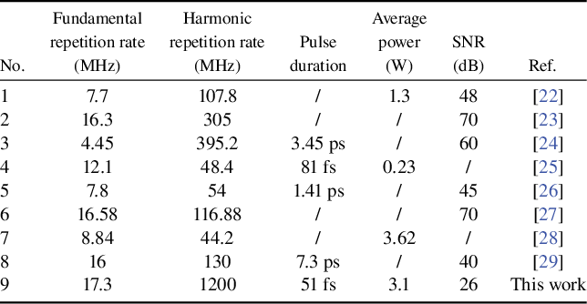
Table 1 Summary of harmonic mode-locking in MOs.
In this work, to decrease the length in the MO, the nonlinear polarization rotation (NPR) mechanism is used to initiate the MO. The advantage of this approach is that the introduced intensity modulation can significantly broaden the spectrum of the pulse. By adjusting the polarization control device, stable mode-locking can be achieved, allowing the laser to operate independently of long fibers while still obtaining sufficient nonlinear effects. Moreover, the NPR mechanism can enhance the Kerr nonlinear effect in fibers while providing a flexible output coupling ratio. Furthermore, the modulation depth in the MO can be controlled by adjusting the filter separation, thereby minimizing its impact on the repetition frequency. Through optimizing filter separation and pump power, it is possible to achieve GHz HML with high average power and short pulse duration. In addition, the HML approach reduces the challenges caused by shortening the cavity length to a certain extent.
Based on the above, an MO is constructed, leveraging the NPR mechanism to initiate mode-locking. In the experiment, gain fiber with a 5 μm core diameter is used to enhance the overlap efficiency between the pump source and the gain medium. The smaller core fiber can improve the gain efficiency and amplify the nonlinear effects within the fiber, thereby supporting the higher-order HML operation. In addition, the effect of filter separation on HML is investigated. Notably, the HML order decreases with increasing filter separation, due to the increased modulation depth. A maximum 93rd-order HML pulse is realized, corresponding to a repetition rate of 1.614 GHz. By optimizing the filter separation, the laser can generate HML of the 69th order, corresponding to a repetition rate of 1.2 GHz, with an average power exceeding 3.1 W. The pulses can be compressed to 51 fs through a grating-pair compressor. Table 1 provides a summary of HML in MOs reported in recent years. To the best of our knowledge, this is the first time a GHz repetition rate has been achieved in an MO while maintaining high average power and short pulse duration.
2 Experimental setup
As illustrated in Figure 1, in the first arm, a 1.5 m long ytterbium-doped double-clad fiber (YDF2, Yb1200-10/125, LIEKKI) is used as a gain medium. The gain fiber is co-pumped by multimode laser diodes (LDs) with power up to 9 W at 976 nm through fusion spliced combiners. For easy control and adjustment in filter separation (∆λ f), a 600 lines/mm reflection grating in combination with a collimator is used as a variable spectrum filter (grating filter), and the 3 dB bandwidth is 2.3 nm. By moving the collimator, the transmitted central wavelength of the grating filter could be tuned from 1040 to 1047 nm. This adjustment leads to an increment in ∆λ f between the two filters. In the second arm, the gain fiber (YDF1, Yb1200-5/130, LIEKKI) is 4.5 m long and is pumped by a multimode LD with power up to 27 W. The central wavelength of the bandpass filter (BPF) is 1040 nm with a 3 dB bandwidth of 3 nm. An NPR configuration is constructed to initialize the laser. It incorporates a pair of quarter-wave plates (QWPs), a half-wave plate (HWP) and a polarization beam splitter. Two isolators are incorporated in the cavity to ensure unidirectional oscillation. The output pulses are subsequently dechirped using a grating compressor composed of two transmission gratings (1000 lines/mm).
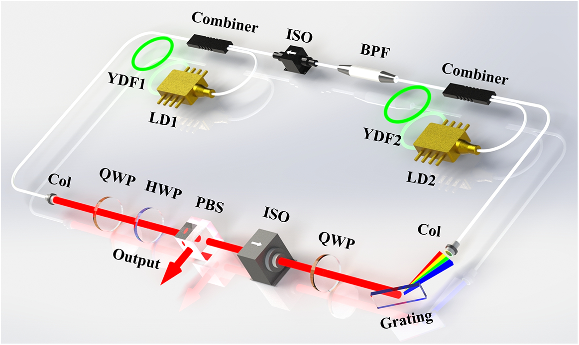
Figure 1 Schematic setup of the MO for generating GHz harmonic mode-locking. Col, collimator; YDF, Yb-doped fiber; BPF, bandpass filter; QWP, quarter-wave plate; HWP, half-wave plate; PBS, polarization beam splitter; ISO, isolator; LD, laser diode.
3 Results
To initiate the MO, it is essential to overlap the two filters so that the low-peak-power noise can be easily transmitted in the cavity, thereby initiating mode-locking[ Reference Pitois, Finot, Provost and Richardson 30 ]. Consequently, the center wavelength of the grating filter is tuned to 1040 nm to match that of the BPF, resulting in a ∆λ f at 0 nm. By rotating the plates between the two arms, the initial mode-locked pulses can be achieved under the NPR mechanism. The corresponding pump powers emitted from LD1 and LD2 are 1.25 and 1.64 W, respectively. Once mode-locking is initiated, the stable mode-locking operation can be sustained by increasing the pump power and adjusting the output coupling ratio. As the ∆λ f increases to 3 nm, a mode-locking state characterized by a sudden broadening spectrum (as shown in Figure 2(a)) is obtained. This phenomenon indicates the genuine transition of the laser into the MO mechanism. Figure 2(b) presents the measured pulse train with an interval of 57.6 ns, corresponding to the fundamental repetition rate of 17.36 MHz. The radio frequency (RF) spectrum around this fundamental repetition rate is illustrated in Figure 2(c), showing a signal-to-noise ratio (SNR) of up to 73 dB.
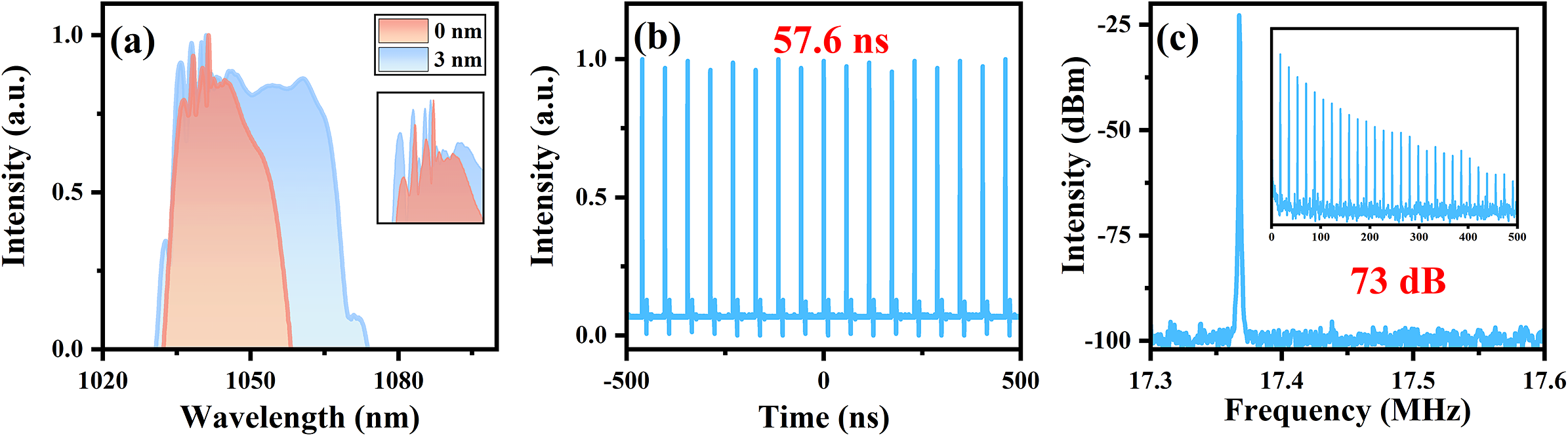
Figure 2 Experiment results. (a) Spectra: red is the mode-locked spectrum when the ∆λ f is 0 nm; blue is the mode-locked spectrum when the ∆λ f is 3 nm; inset shows the zoom-in of the CW state. (b) Pulse train. (c) RF spectrum.
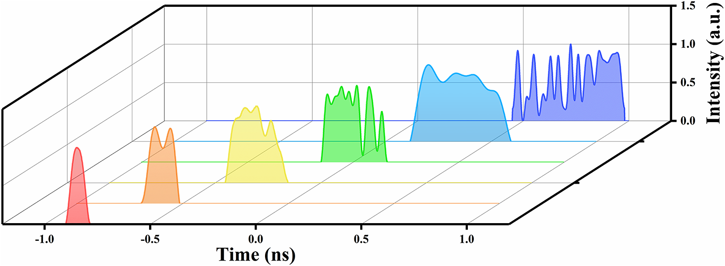
Figure 3 Evolution of the pulses with increasing pump power.
With further increasing pump power, multiple pulses emerge in the cavity due to energy quantization. These pulses can either form a tight packet or be distributed randomly throughout the cavity[ Reference Li, Zhang, Hao and Yang 31 ]. Then, the polarization and pump power need to be carefully controlled to balance the gravitational and repulsive forces between adjacent pulses. This balance results in pulse envelopes at equal intervals, enabling the pulses to operate in burst mode. Furthermore, the number of pulses in the packet can be increased by enhancing the pump power. To further explore the characteristics of these pulse bursts, the evolution of the output parameters is measured. As shown in Figure 3, the pulse envelope gradually broadens, with widths ranging from 0.13 to 0.53 ns as the pump power increases. This broadening is attributed to intensified pulse splitting, which results in growing sub-pulses, thereby expanding the overall envelope. However, due to the bandwidth limitations of the oscilloscope, accurately measuring the number of sub-pulses and their intervals within the burst is not feasible. It is also noteworthy that the intervals between pulses are not uniform, which may be attributed to random dispersive waves. In addition, in multi-pulse regimes, as pump power increases, the pulse interaction rises. The intensity of one pulse can affect the phase of another, potentially leading to asymmetric pulse profiles and splitting. Furthermore, weak-intensity fluctuations may arise from competition between adjacent pulses. The occurrence of the above phenomenon offers a promising approach for generating GHz pulses by effectively managing the nonlinearity, gain and output coupling ratio.
Subsequently, as the pump power continues to increase, slight adjustments are made to the polarization within the cavity by rotating the QWP and HWP. This introduced disturbance disrupts the balance between gain and loss, leading to the disappearance of the burst mode. Simultaneously, numerous pulses emerge, exhibiting randomly distributed intervals among the sub-pulses. Through the optimization of polarization to balance the repulsion and attraction between sub-pulses, a novel operational regime has been observed[ Reference Liu and Pang 32 ]. In this case, the intervals between adjacent pulses become uniform, allowing the laser to achieve HML operation. As the pump power is continuously increased, Figure 4 illustrates the output pulse trains for various orders of HML operation: 11th order (191 MHz), 14th order (243 MHz), 35th order (607 MHz), 45th order (781 MHz), 51st order (885 MHz) and 59th order (1024 MHz) HML. The intervals between adjacent harmonic pulses are 5.237, 4.115, 1.647, 1.280, 1.130 and 0.976 ns, respectively, which are the reciprocals to repetition frequency. The insets of Figure 4 reveal the SNRs of the HML pulses, respectively, which can confirm stable HML operation. Consequently, in the MO, GHz mode-locking can be achieved by the HML approach.
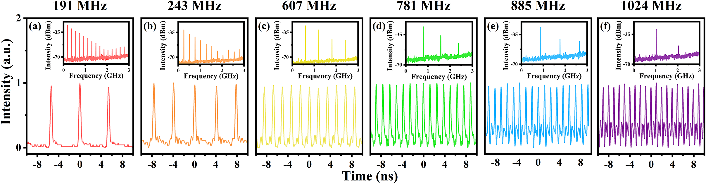
Figure 4 HML pulse train and RF spectrum: (a) 11th, (b) 14th, (c) 35th, (d) 45th, (e) 51st and (f) 59th harmonic orders.
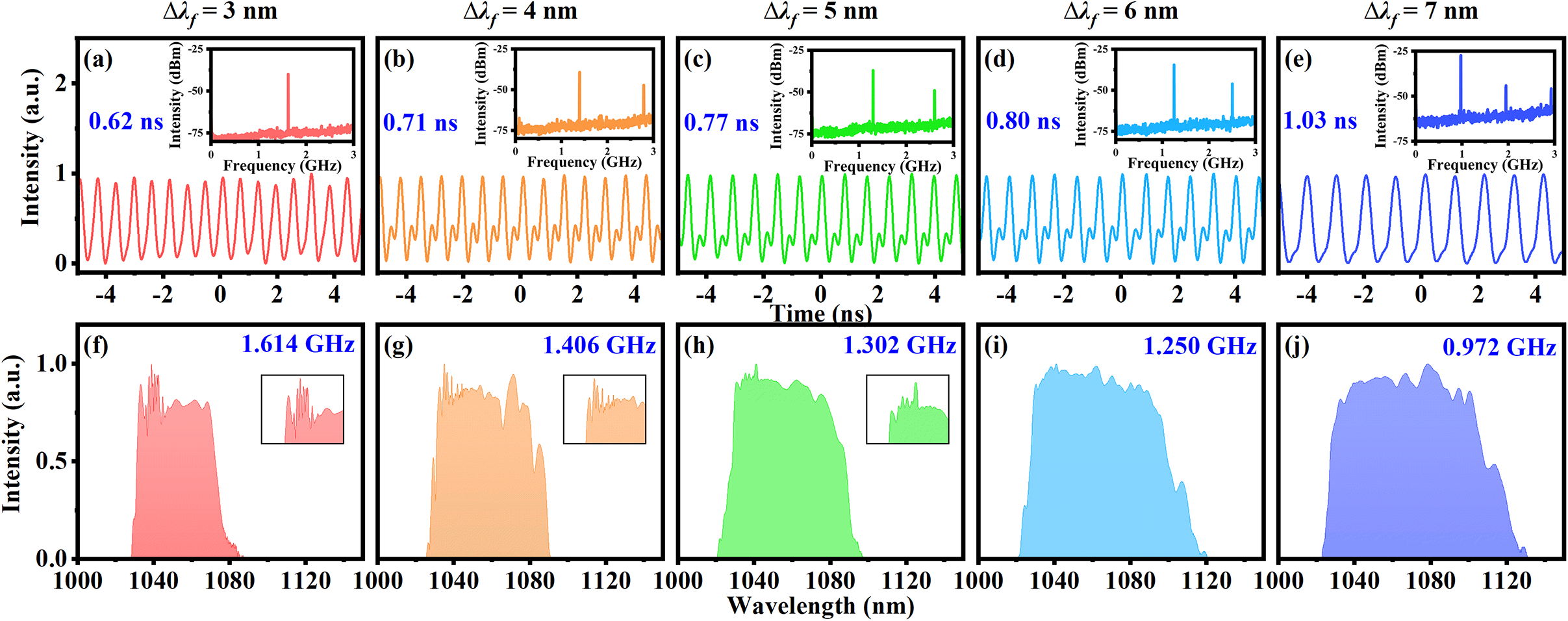
Figure 5 Experimental results under different ∆λ f. (a)–(e) Pulse train; inset, RF spectrum. (f)–(j) Spectra; inset, zoom-in of the CW state.
Due to the mechanism of MO, the modulation depth increases with the increment in ∆λ f, resulting in enhanced output performance. To improve output performance, the relationship between ∆λ f and the generation of GHz is further investigated. Figure 5 presents the pulse train with the maximum achievable HML repetition rate under different ∆λ f, along with the corresponding spectra. As the ∆λ f and pump power increase, the spectra exhibit broadening and red-shifting. Interestingly, Figure 5 reveals that the maximum order of HML decreases as ∆λ f increases, declining from an initial 1.614 to 0.972 GHz. This phenomenon is hypothesized to result from the increasing modulation depth in the MO as the ∆λ f increases. Although sufficient modulation depth enables the production of a broader spectrum, it simultaneously impedes pulse splitting, thereby obstructing the generation of GHz. In addition, further increment in pump power can disrupt mode-locking, when the modulation depth becomes larger. Thus, in MO lasers, there exists an inherent contradiction between achieving a high repetition frequency and spectral broadening, which corresponds to a shortened pulse duration. Consequently, it is essential to establish a balance between these factors to determine the optimal operating parameters. Achieving this balance allows for the simultaneous achievement of high repetition frequency, high average power and short pulse duration.
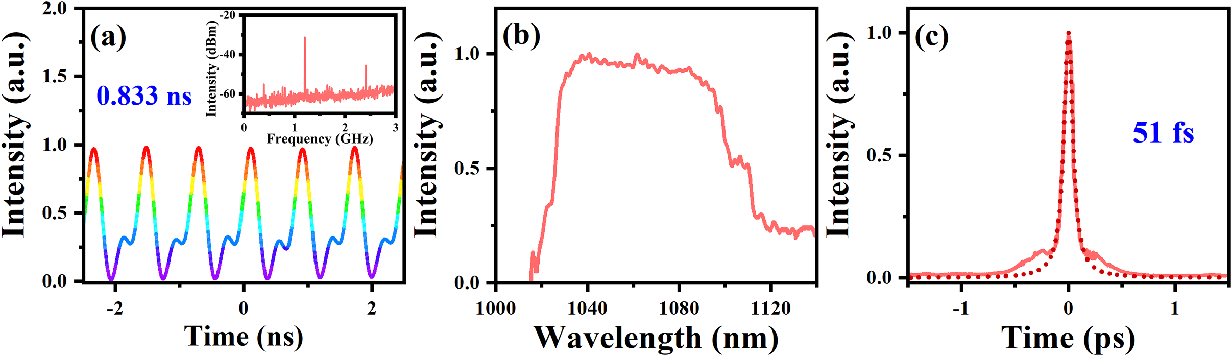
Figure 6 Experimental results. (a) Pulse train; inset, RF spectrum. (b) Spectrum. (c) Autocorrelation trace.
In the MO, the continuous wave (CW) component in spectra can, to some extent, reflect the intensity of the modulated depth. Insufficient modulation depth fails to suppress the CW component, leading to a pronounced CW peak at 1040 nm, as shown in Figures 2(a) and 5(f). As ∆λ f increases, the modulation depth becomes larger, gradually suppressing the CW, as illustrated in Figures 5(g)–5(j). Notably, when ∆λ f reaches 7 nm, the CW component is fully suppressed, indicating a higher modulation depth. Although this allows for a wider spectrum, it also reduces the harmonic order. Consequently, maintaining the GHz harmonic mode-locked state becomes difficult when ∆λ f is over 7 nm.
Table 2 Output of harmonic mode-locking in this MO.
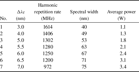
Based on the insights obtained from the previous experiments, further optimization of the laser parameters is conducted. Table 2 summarizes the spectral widths and average output powers at various ∆λ f values. Specifically, setting the ∆λ f to 6.5 nm enables the laser to meet the requirements for high repetition frequency, high average power and a wider spectrum. The specific tests are as follows. The central wavelength of the grating filter is adjusted to 1046.5 nm. As the pump power is increased, the QWP and HWP are slightly rotated to adjust the output coupling ratio. When the pump powers from LD1 and LD2 are set to 15.4 and 8.7 W, respectively, the maximum HML repetition rate is obtained, as shown in Figure 6(a). The interval between adjacent pulses is 0.833 ns, corresponding to a repetition rate of 1.2 GHz (69th order). Figure 6 presents the detailed characteristics of the pulses with a repetition rate of 1.2 GHz. The SNR, as shown in the inset, indicates stable operation in the laser. The output spectrum is depicted in Figure 6(b), with a central wavelength of 1051 nm and a 10 dB bandwidth of 71 nm. As illustrated in Figure 6(c), after compression, the pulse duration is reduced to 51 fs. The pulse has a small amount of pedestal structure, which we estimate to comprise less than 10% of the pulse energy. Under optimum parameters, the maximum output average power is 3.1 W. To the best of our knowledge, this is the first time a GHz repetition rate in an MO has been achieved while maintaining watt-level average power and short pulse duration.
The stability of the MO is also assessed at the maximum average power. The output average power is continuously monitored and recorded at 1 s intervals, with the results presented in Figure 7. The root mean square (RMS) fluctuation of the recorded power values is calculated to be less than 0.30%, indicating a high level of power stability.
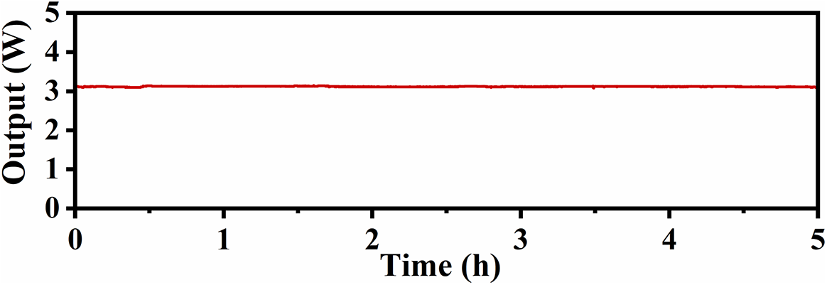
Figure 7 Power stability measurement of the mode-locked MO within 5 hours.
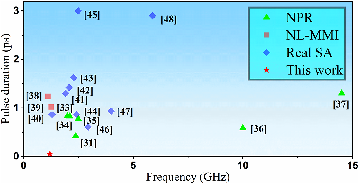
Figure 8 Overview of GHz harmonic mode-locking in different configurations[ Reference Pang, Jiang, He, Wong, Onishchukov, Joly, Ahmed, Menyu and Russell 33 – Reference Meng, Niang, Guesmi, Salhi and Sanchez 48 ].
4 Conclusion
In conclusion, we construct an MO capable of achieving a GHz repetition rate through HML. The MO utilizes the NPR mechanism in conjunction with a gain fiber featuring a 5 μm core diameter. This configuration enhances gain efficiency and amplifies nonlinear effects, thereby facilitating higher-order HML operations. Notably, the HML order decreases with increasing filter separation due to increased modulation depth. A maximum HML order of 93 is obtained, corresponding to a repetition rate of 1.6 GHz. By optimizing the filter separation, the laser is able to generate pulses at a repetition rate of 1.2 GHz (69th order), with an average power exceeding 3 W. The pulses are compressed to 51 fs using a grating-pair compressor. Figure 8 provides a summary of the GHz HML reported in recent years[ Reference Pang, Jiang, He, Wong, Onishchukov, Joly, Ahmed, Menyu and Russell 33 – Reference Meng, Niang, Guesmi, Salhi and Sanchez 48 ]. To the best of our knowledge, these results represent the highest average power and shortest pulse duration in the field of GHz HML.
Acknowledgements
This work was supported by the National Natural Science Foundation of China (NSFC) (Grant No. 12164030), the Young Science and Technology Talents of Inner Mongolia (Grant No. NJYT22101), the Central Government Guides Local Science and Technology Development Fund Projects (Grant No. 2023ZY0005) and the Science and Technology Plan Projects of Inner Mongolia Autonomous Region of China (Grant No. 2023KYPT0012).


 Open access