


1 Introduction
Eye-safe 2.1 μm high-energy, injection-seeded solid-state lasers show considerable potential for radar applications, such as differential absorption radar for methane detection and coherent Doppler wind radar[ Reference Henderson, Hale, Magee, Kavaya and Huffaker 1 – Reference Zhang, Gao, Wang, Na, Gao, Zhang and Huang 3 ]. Because Ho:yttrium aluminum garnet (YAG) has the advantages of a long upper-state lifetime, robust mechanical properties and fascinating thermal conductivity, it is an excellent choice for emitting 2.1 μm high-energy pulses[ Reference Mi, Tang, Wei, Yao, Li, Yang, Dai and Duan 4 , Reference Wang, Dai, Wu, Ju and Yao 5 ]. Considering the coherent Doppler wind radar transmitter, the single-frequency laser should have a narrow linewidth, long pulse width and high energy to ensure measurement accuracy and long-range detection. The injection of seed lasers into Q-switched lasers with long cavity lengths and high energy is a proven technique for obtaining a single-frequency pulsed laser that meets the requirements[ Reference Chen, Yu, Petros, Bai, Upendra and Kavaya 6 – Reference Zhang, Gao, Wang, Na, Zhang, Ye, Gao and Zhang 8 ]. Using a Q-switched Ho:YAG ring laser with six mirrors resonantly pumped by a Tm:YAG laser as a slave laser, Dai et al. [ Reference Dai, Ju, Yao, Shen, Wang and Wang 9 ] demonstrated a single-frequency injection-seeded laser in 2012. The seed laser is a diode-pumped Tm,Ho:YAG laser whose single-frequency operation is achieved by two Fabry–Pérot etalons. In 2017, Wang et al. [ Reference Wang, Gao, Na, Zhang, Ye and Gao 2 ] described a single-frequency Q-switched Ho:YAG linear folding laser, injection-seeded by a Ho:YAG nonplanar ring oscillator (NPRO). In the same year, Na et al. [ Reference Na, Gao, Wang, Zhang and Gao 10 ] used the same seed laser to achieve an injection-seeded Ho:YAG laser and increased the repetition rate to 1 kHz. Subsequently, Na et al. [ Reference Na, Gao, Wang, Zhang, Gao, Zhang and Wang 11 ] investigated the effect of the polarization state of the Ho:YAG NPRO seed laser on the output characteristics of the injection-seeded Ho:YAG laser. From the above results, it can be seen that among injection-seeded lasers, NPRO and linear cavities with Fabry–Pérot etalons are the most common seed lasers. Compared with the NPRO and intracavity Fabry–Pérot etalon methods, the unidirectional ring laser has the advantages of good stability, flexible cavity selection, elimination of spatial hole burning and simple frequency tuning, and is suitable for anisotropic and isotropic crystals[ Reference Huang, Chen, Wang, Zhang, Wang and Gao 12 , Reference Shen, Clarkson, Cooper and Williams 13 ]. In addition, the seed laser should be alignment insensitive, which increases the probability of successful injection seeding.
The Doppler frequency resolution of coherent Doppler radar is related to the pulse width, so a slave Q-switched laser with a cavity length of several meters is usually chosen. This will increase the alignment sensitivity of lasers composed of conventional optical elements, reducing the reliability of radar systems in harsh environments. Corner cubic reflectors (CCRs) have retroreflective properties that make lasers with CCRs insensitive to changes in the ambient temperature and crystal thermal lens, as well as vibrations[ Reference Peck 14 – Reference Ma, Li, Lin, Yu, He and Zhang 16 ]. The advent of the CCR made it possible to build a resonator with a longer cavity length that is insensitive to misalignment in any direction. In 2018, Wu et al. [ Reference Wu, Wang, Dai, Ju, Yao and Wang 17 ] presented a Ho:yttrium lithium fluoride (YLF) laser with a double CCR, which achieved a 733 mW single longitudinal mode (SLM) laser output based on the Faraday effect. Immediately thereafter, Wang et al. [ Reference Wang, Dai, Wu, Ju and Yao 5 ] used the same structure to study a Ho:YAG laser under Q-switched operation. In 2019, Wang et al. [ Reference Wang, Dai, Liu, Ju and Yao 18 ] built a Q-switched Ho:YLF five-mirror ring laser and achieved dual-wavelength seed injection. The seed lasers were two identical single-frequency Ho:YLF ring lasers both consisting of two CCRs. In 2020, Wang et al. [ Reference Wang, Ju, Dai, Yan, Chen, Fang, Daun and Yao 19 ] described a high-power SLM Ho:YLF laser based on a pair of CCRs that achieved continuous frequency tuning of 5.5 pm through two wedge prisms. In 2021, Zhang and Ju[ Reference Zhang and Ju 20 ] selected a double CCR ring cavity for a Q-switched Er:YAG slave laser and successfully achieved injection seeding. However, an injection-seeded Ho:YAG laser in which both the slave and seed lasers adopt a double CCR structure has not been reported. In radar systems, the high alignment insensitivity of single-frequency lasers can significantly improve radar reliability.
In this paper, we present an injection-seeded Q-switched Ho:YAG single-frequency laser with fascinating alignment-insensitivity characteristics. The seed laser is a Ho:YAG ring laser consisting of two CCRs, which operates at 2096.667 nm when generating 830 mW of SLM power. The single-frequency pulse energy obtained at 100 Hz is 7.3 mJ, and the pulse width is 161.2 ns. The single-frequency pulse energy of 7.3 mJ is scaled to 33.3 mJ by the Ho:YAG amplifier. The beam quality M 2 factors of the amplifier in the x and y directions are 1.43 and 1.21, respectively. The single-frequency pulse spectrum has a half-width of 4.12 MHz. An injection-seeded single-frequency laser using two double CCR ring cavities has been demonstrated for the first time.
2 Experimental setup
Figure 1 shows a schematic diagram of the single-frequency injection-seeded Ho:YAG laser. It consists of the following three parts: a double CCR Ho:YAG seed laser and a double CCR Q-switched Ho:YAG slave laser, as well as a master oscillator power amplifier (MOPA) and heterodyne beating system.

Figure 1 Schematic diagram of the single-frequency injection-seeded Ho:YAG laser. The upper left part of the schematic is the transmission path of the oscillating light inside the CCR. Fiber 1–3, 1908 nm fiber lasers; f1–f9, plano-convex lenses (with focal lengths of f1 and f3 being 160 mm, f2, f4 and f5 400 mm, f6 and f7 200 mm, f8 600 mm, f9 240 mm); AOM, acousto-optic modulator; HWP, half-wave plate; CCR1–CCR4, corner cube reflectors; IOS, isolator; F-R, Faraday rotator; S1, S2, splitters; HR is coated with 1.9–2.1 μm high reflection film; thin-film polarizers TFP1–TFP6 are coated with 1.9 μm pump light and 2.1 μm S-polarized high reflection film as well as 2.1 μm P-polarized high transmittance film.
Seed lasers play an extremely critical role in injection-seeded lasers. Their power, beam quality factor, linewidth and operating frequency are key factors in whether injection seeding can be achieved[ Reference Chen, Gao and Wang 21 , Reference Barnes and Barnes 22 ]. The Ho:YAG seed laser is composed of CCR1 and CCR2, and is pumped by a 1908 nm fiber laser (the maximum output power of Fiber 1 is 15.7 W, with a core diameter of 25 μm and a numerical aperture of 0.1). The diameter of the CCR base surface coated with an anti-reflective coating of 1.9–2.1 μm is 40 mm. The CCR height is 35 mm. The collimated pump light from Fiber 1 is focused by f1 at the Ho:YAG crystal position and the resulting spot diameter is about 0.8 mm. The dimension of the 0.5% (atomic fraction) Ho:YAG crystal with high transmittance (transmittance greater than 99.7%) at 1.9–2.1 μm at both ends is 50 mm in length and 4 mm in diameter. The crystal temperature is precisely controlled at 15°C by a thermoelectric cooler that is in contact with a water-cooled copper heat sink. TFP1 and TFP2 are not only used to inject and dump pump light, but also to extract oscillating light, that is, as output couplers. f2 is disposed symmetrically to the Ho:YAG crystal to compensate for the thermal lensing of the crystal. The role of the half-wave plate (HWP) is to control the polarization degradation of the oscillating light so that the seed laser operates at an optimal output rate. An uncoated 0.3 mm Fabry–Pérot etalon is used to tune the frequency. A Faraday rotator (F-R) is configured in the ring resonator to force unidirectional operation to achieve SLM output. A portion of the seed light is coupled to the fiber combiner as the local oscillation light for heterodyne beating measurement. The other part of the seed light is frequency shifted through the acousto-optic modulator (AOM) and injected from the TFP4 into the slave laser. The isolator (IOS) and HWP form an isolation device that prevents optical damage to the seed laser.
The structure of the Q-switched Ho:YAG slave laser is the same as that of the seed laser, but the internal components of the cavity are slightly different and are pumped by a 1908 nm fiber laser (the maximum output power of Fiber 2 is 22.7 W, with a core diameter of 25 μm and a numerical aperture of 0.1). A long pulse width can improve the Doppler resolution of coherent Doppler wind radar, so the distance between the two CCRs is set to 1.3 m, resulting in a cavity length of 2.7 m. The pump laser has a spot diameter of 0.8 mm at the center of the Ho:YAG. The crystal parameters and operating environment used in the slave laser are the same as those of the seed laser. The thermal lensing of the crystal is compensated by two identical lenses, f4 and f5, arranged symmetrically at both ends of the crystal. The Q-switch operation is performed by an AOM placed inside the cavity. The uncoated 0.3 mm Fabry–Pérot etalon has two functions. One is as a resonant signal extraction mirror. The other is to tune the frequency of the slave laser. Two wedge-shaped prisms fixed to a piezoelectric transducer (PZT) scan the cavity length under the voltage drive, and the working principle can be found in Ref. [Reference Wang, Ju, Dai, Yan, Chen, Fang, Daun and Yao19]. The two end faces of the wedge-shaped prisms have a high transmittance at 2.1 μm. In this experiment, the single-frequency pulsed laser is obtained by ‘ramp-hold-fire’ technology[ Reference Henderson, Yuen and Fry 23 ]. The S-polarized seed laser enters the slave laser after being reflected by TFP4 and circulates clockwise in the slave laser. Due to the depolarization of the CCR, the seed laser is not a linearly polarized laser when traveling to TFP3, and there is a P-polarized component at this time. The P-polarized component passes through TFP3 for the next cycle, and the remaining S-polarized seed laser is reflected out of the cavity by TFP3. The P-polarized component is the effective seed laser injected into the slave laser. The P-polarized seed laser induces the upper energy level inversion particles of the crystal to generate stimulated radiation and is amplified. When the P-polarized laser circulates for one cycle, the S-polarized component generated by depolarization is reflected out of the cavity by TFP3, and the ratio of the S-polarized component to the total laser (S+P) is considered the output rate. The optimum output rate can be achieved by adjusting the HWP to change the polarization state of the intracavity oscillation laser.
A single-pass amplifier using two identical Ho:YAG crystals placed adjacent to each other is used to amplify the single-frequency pulse energy. The Fiber 3 (the maximum output power of Fiber 3 is 49.1 W, with a core diameter of 25 μm and a numerical aperture of 0.1) pump laser is focused by f8 at the junction of the two crystals, producing a 0.8 mm waist spot diameter. At the same time, the single-frequency pulse laser from the slave laser is focused by f9 to produce a waist spot with a diameter of 0.8 mm between the two crystals. A portion of the amplified single-frequency pulse laser is coupled to the fiber combiner and mixed with the seed laser. The beating signal is recorded by a digital oscilloscope and the spectral intensity distribution of the pulse is obtained by fast Fourier transform (FFT) processing.
3 Results and discussion
The center wavelength of the seed laser measured by a wavelength meter (Bristol 721A, ±0.2 pm accuracy) is 2096.666 nm, as shown in Figure 2. The inset shows the scanning results of the Fabry–Pérot interferometer, which shows that the seed laser operates in SLM.

Figure 2 Wavelength and Fabry–Pérot interferometer spectrum of the Ho:YAG seed laser.
Figure 3 shows the output power of the seed laser. The maximum available SLM power is 830 mW at 14 W pump power (the absorbed pump power is 11.3 W). The fluctuations of the output power and wavelength of the seed laser within 540 s are shown in Figure 4. The standard deviations of power and wavelength are 0.006 W and 0.004 nm, respectively, and power instability is 0.7%.

Figure 3 Output power of the Ho:YAG seed laser.

Figure 4 The fluctuations of the power and wavelength of the Ho:YAG seed laser.
Figure 5 shows the effect of the angular deviation of the CCR on the output power. When CCR1 is tilted 2° horizontally or 0.62° vertically, the power drops by 4.5% and 6%, respectively. The output power versus the CCR1 travel distance on the vertical optical path (parallel pages move up or down) is shown in Table 1. When the moving distance is 0.1 mm, the output power decreases by 9.2%. The results show that the seed laser exhibits excellent alignment-insensitive characteristics.
Table 1 Output power versus CCR1 travel distance.


Figure 5 Effect of angular deviation of the CCR on the output power of seed laser under SLM and Q-switched operation.
We first investigated the Ho:YAG slave laser under continuous-wave operation. To reduce the frequency difference with the seed laser, the wavelength of the slave laser is tuned to 2096.773 nm by Fabry–Pérot etalon, as shown in Figure 6. Output power of 2.25 W is obtained at 17.3 W pump power, and the slope efficiency is 30.3%.

Figure 6 Wavelength of the Q-switched Ho:YAG laser.
The effect of the angular deviation of CCR3 on output power is shown in Figure 7. CCR3 is tilted to 7.2° horizontally with a 5% drop in output power, and 5.3° vertically with a 13% drop in output power. Figure 8 shows the variation of output power with the distance traveled by CCR3 along the vertical optical path, with a 7.8% drop in output power corresponding to a travel distance of 0.2 mm. Notably, the alignment insensitivity of the slave laser is significantly better than that of the seed laser. A double CCR laser with the same cavity length as the seed laser and the same components in the cavity as the slave laser is used as a comparative experiment. The experimental results show two reasons for the superior alignment insensitivity of the slave laser. One is that the internal components of the laser are different, as shown in Figure 5. The other is that the length of the cavity is different, as shown in Figure 7. Here CCR1 is used as the contrast CCR, which represents the CCR in the comparison experiment.

Figure 7 Effect of angular deviation of the CCR on the output power of the Q-switched slave laser with different cavity lengths.

Figure 8 Effect of travel distance of CCR3 on the output power.
Figure 9 shows the output energy and pulse width as functions of pump power for the Q-switched Ho:YAG laser with and without injection seeding at a 100 Hz repetition rate. Under the same pump power, the output pulse energy in single-frequency operation is significantly higher than in free running. The maximum pulse energies obtained in single-frequency and free-running operations are 7.3 and 5.6 mJ at a pumping power of 17.3 W (the absorbed pump power is 15.4 W), corresponding to pulse widths of 161.2 and 166.1 ns, respectively. Figures 10(a) and 10(b) represent the temporal profiles of the single pulse at 161.2 and 166.1 ns, respectively.

Figure 9 Energy and pulse width of the Q-switched Ho:YAG laser.
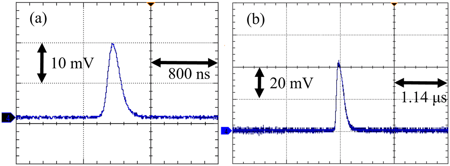
Figure 10 The pulse temporal profiles of the Q-switched Ho:YAG laser (a) with injection seeding and (b) without injection seeding.
There is a process for establishing the pulse. When the Q-switch is turned on, the laser starts to oscillate, and the number of photons Φ increases very slowly for a long period after the oscillation starts at t 0 = 0, its value is always small and the probability of stimulated radiation is very small. At this time, spontaneous radiation predominates. When the oscillation lasts until t = t D, the number of photons Φ increases to ΦD and the avalanche process is formed; Φ increases rapidly and the stimulated radiation quickly exceeds the spontaneous radiation and becomes dominant. Therefore, the pulse requires a certain delay time t D from the establishment of the oscillation to the formation of the giant pulse laser, that is, the build-up time. The shortening of the pulse build-up time is a criterion to judge the success of injection locking. Figure 11 shows the laser pulse build-up time of the Q-switched Ho:YAG laser. The build-up time of single-frequency pulses is significantly shorter when the pump power is the same. This is attributed to the fact that the single-frequency pulse laser is generated by the stimulated radiation induced by the seed laser beam. The build-up time difference between single-frequency pulses and free-running pulses gradually decreases with increasing pump power.

Figure 11 The build-up time of the Q-switched Ho:YAG laser with and without injection seeding.
The amplification results of the Ho:YAG amplifier for the 7.3 mJ single-frequency pulse energy from the slave laser are shown in Figure 12. The pulse energy obtained at a pump power of 42.4 W (the absorbed pump power is 36.7 W) is as high as 33.3 mJ, corresponding to a gain of 4.6 dB. The output energy fluctuations of the amplifier are recorded over 10 min, as shown in Figure 13. The average energy is 33.51 mJ with a standard deviation of 0.33 mJ.

Figure 12 Output energy of the Ho:YAG amplifier.

Figure 13 Energy fluctuation of the Ho:YAG amplifier.
The beam quality of the Ho:YAG amplifier with an output energy of 33.3 mJ is measured using the 90/10 knife-edge method[ Reference Wang, Dai, Liu, Ju and Yao 18 ]. The sharp edge of the knife moves perpendicular to the output laser. When the output energy changes from 90% of the maximum energy to 10%, the distance traveled by the knife multiplied by 0.78 is defined as the spot radius.
The beam radius along the beam propagation direction is shown in Figure 14. By fitting a Gaussian curve to the measured data, the M 2 factors of 1.43 and 1.20 are evaluated for the x and y directions, respectively.

Figure 14 Beam quality of the Ho:YAG amplifier.
The beating signal measured by the heterodyne beating technique is recorded by a digital oscilloscope, as shown in Figure 15(a). The beating signal is analyzed by FFT and the center frequency of the pulse spectrum is obtained as 77.27 MHz with a full width at half-maximum (FWHM) of 4.12 MHz, as shown in Figure 15(b).

Figure 15 (a) Beating signal. (b) The FFT spectrum.
4 Conclusion
In summary, an injection-seeded Ho:YAG single-frequency laser with excellent alignment-insensitive performance is described. The Ho:YAG seed laser operates at a wavelength of 2096.667 nm with an available power of 830 mW. Tilting CCR1 in the seed laser by 2° horizontally or 0.62° vertically reduces the output power by only 4.5% and 6%, respectively. The standard deviations of output power and wavelength fluctuations are 0.006 W and 0.004 nm, respectively, with power instability of 0.7%. The Q-switched slave laser is also a Ho:YAG ring laser with two CCRs. When CCR3 is tilted horizontally by 7.2° or vertically by 5.3°, the output power decreases by 5% and 13%, respectively. A long cavity length and multiple longitudinal mode outputs give the slave laser better alignment insensitivity than the seed laser. At 100 Hz, a pulse energy of 7.3 mJ is scaled to 33.3 mJ by the Ho:YAG amplifier. The output energy fluctuation of the amplifier is recorded over 10 min with a standard deviation of 0.33 mJ. The beam quality factors of the amplifier are ${M}_x^2=1.43$
and
${M}_x^2=1.43$
and ${M}_y^2=1.20$
, respectively. The FWHM of 4.12 MHz is determined by the measurement results of the heterodyne beating technique. Experimental results show that the alignment-insensitive double CCR ring cavities are promising, ensuring the robust operation of injection-seeded lasers in harsh environments. This alignment-insensitive, high-energy Ho:YAG single-frequency laser is a potential candidate for Doppler wind radar.
${M}_y^2=1.20$
, respectively. The FWHM of 4.12 MHz is determined by the measurement results of the heterodyne beating technique. Experimental results show that the alignment-insensitive double CCR ring cavities are promising, ensuring the robust operation of injection-seeded lasers in harsh environments. This alignment-insensitive, high-energy Ho:YAG single-frequency laser is a potential candidate for Doppler wind radar.


 Open access