


1 Introduction
There have been two published reviews of ultra-high-power lasers separated by nearly two decades; the first by Backus et al. [Reference Backus, Durfee, Murnane and Kapteyn1] in 1998, when there was only one petawatt class laser in operation[Reference Perry, Pennington, Stuart, Tietbohl, Britten, Brown, Herman, Golick, Kartz, Miller, Powell, Vergino and Yanovsky2], and the second by Danson et al. [Reference Danson, Hillier, Hopps and Neely3] some 17 years later, which identified approximately fifty petawatt class lasers either operational, under construction or in the planning phase. These review papers were cited by the Nobel Committee for Physics in its 2018 award to Strickland and Mourou in its Scientific Background paper[4] ‘Groundbreaking Inventions in Laser Physics’. In addition to these the National Academy of Sciences, Engineering and Medicine in the USA published a report in December 2017 ‘Opportunities in Intense Ultrafast Lasers: Reaching for the Brightest Light’[5], which summarized the current status of high-power lasers, highlighting the decline in this activity within the USA in recent years, and making recommendations of how this should be remedied.
A special mention should also be made to the work of ICUIL. ICUIL, the International Committee on Ultra-High Intensity Lasers, is an organization concerned with international aspects of ultra-high-intensity laser science, technology and education. This was formed in 2003 following the work of the OECD (Organisation for Economic Co-operation and Development) Global Science Forum[6] under the International Union of Pure and Applied Physics (IUPAP)[7]. ICUIL has a very active programme of work and maintains a track of ultra-high-intensity lasers on its website[8]. It also hosts a biennial conference to bring the community together for the exchange of information on the subject.
1.1 Introduction – historical perspective
The possibility of using lasers to achieve previously unobtainable states of matter in the laboratory gained much attention following the demonstration of the first pulsed laser in 1960[Reference Maiman9]. In the following few years there was vigorous research activity as attempts were made to increase the peak power and focused intensity in order to reach extreme conditions within the laboratory. Initial jumps of several orders of magnitude in peak power came with the invention of $Q$
-switching[Reference McClung and Hellwarth10], and then mode-locking[Reference Hargrove, Fork and Pollack11–Reference DeMaria, Stetser and Heynau15]. Progress slowed, as illustrated in Figure 1, until the late 1980s, with the development of the technique of chirped pulse amplification (CPA) by Strickland and Mourou[Reference Strickland and Mourou16] at the Laboratory for Laser Energetics (LLE) at the University of Rochester, USA.
$Q$
-switching[Reference McClung and Hellwarth10], and then mode-locking[Reference Hargrove, Fork and Pollack11–Reference DeMaria, Stetser and Heynau15]. Progress slowed, as illustrated in Figure 1, until the late 1980s, with the development of the technique of chirped pulse amplification (CPA) by Strickland and Mourou[Reference Strickland and Mourou16] at the Laboratory for Laser Energetics (LLE) at the University of Rochester, USA.
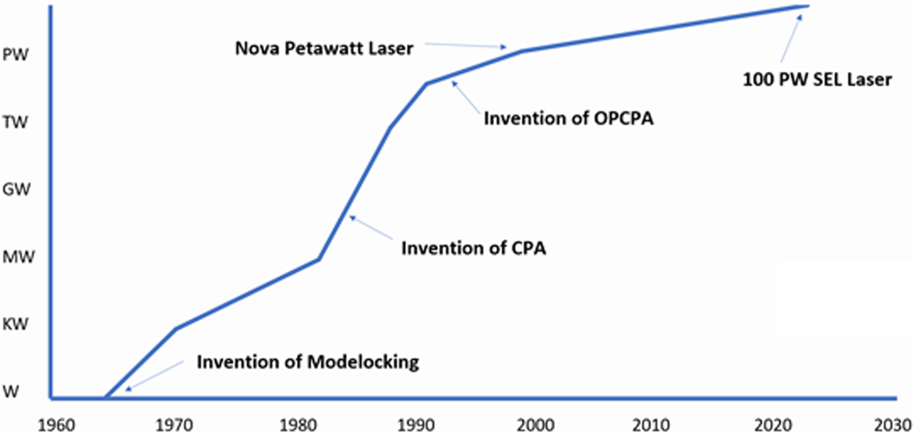
Figure 1. The historical journey to multi-petawatt ultra-short-pulse laser facilities.
A parallel problem existed in radar systems, where short, powerful pulses that were beyond the capabilities of existing electrical circuits were needed. Using dispersive delay lines, the radar pulses could be stretched and amplified prior to transmission, and then the reflected pulse could be compressed, avoiding high-peak powers within the amplifier circuitry[Reference Brookner17]. In the telecommunications industry, work was carried out on the use of prisms[Reference Fork, Martinez and Gordon18] and grating pairs[Reference Martinez19] to compensate for the spectral phase distortions imposed on broad bandwidth laser pulses by long lengths of optical fibre. By putting a telescope inside a grating pair, Martinez produced a method to reverse the sign of the spectral phase that was imparted, thus creating a device that could stretch a pulse and then exactly compress it. These systems were used in stretching pulses prior to propagation along the fibre, then compressing them in order to reduce nonlinear effects.
Strickland and Mourou’s approach was to take the 150 ps output from a commercial mode-locked Nd:YAG oscillator, which was then stretched to 300 ps and spectrally broadened in 1.4 km of optical fibre, using a combination of group velocity dispersion and self-phase modulation. The pulse was then amplified in a Nd:glass regenerative amplifier, and compressed using a Treacy grating pair[Reference Treacy20] which compensated for the second-order spectral phase imposed by the fibre. From the original CPA paper’s conclusion, it states ‘we have shown that by first stretching a chirped optical pulse and then amplifying before compressing, high-peak power pulses can be achieved. To date, we have produced 2 ps pulses with an energy of 1 mJ.’
Due to the limitations of mode-locked lasers operating at 1064 nm, early high-power/energy CPA lasers[Reference Ferray, Lompré, Gobert, L’huillier, Mainfray, Manus, Sanchez and Gomes21–Reference Sauteret, Mourou, Husson, Thiell, Seznec, Gary and Migus24] all relied on the use of self-phase modulation to generate enough bandwidth to support pulses of a few picoseconds[Reference Nikolaus, Grischkowsky and Balant25]. These systems generated large amounts of high-order spectral phase and spectral modulation during the nonlinear process, making optimal compression hard to realize and, moreover, these systems had poor stability due to the nonlinear process. A transformative development was the invention of the transition-metal-doped gain medium titanium-doped sapphire (Ti:Al $_{2}$
O
$_{2}$
O $_{3}$
) in 1986 by Peter Moulton at the MIT Lincoln Laboratory[Reference Moulton26]. It has a very large gain bandwidth (
$_{3}$
) in 1986 by Peter Moulton at the MIT Lincoln Laboratory[Reference Moulton26]. It has a very large gain bandwidth ( ${\sim}$
640 to
${\sim}$
640 to ${\sim}$
1100 nm) that is much larger than other materials and absorbs conveniently at frequency-doubled Nd wavelengths. This naturally led to Ti:sapphire mode-locked oscillators[Reference Spence, Kean and Sibbet27] which allowed much shorter pulses to be produced. These systems could either directly seed Ti:sapphire amplifiers[Reference Barty28] or, if tuned to 1054 nm[Reference Squier, Salin, Coe, Bado and Mourou29], be used to seed existing large-aperture Nd:glass systems. Other developments around this time included a neodymium-based additive-pulse mode-locking system[Reference Phillips, Chang, Danson, Barr, Hughes, Edwards and Hanna30] which could generate pulses at under 0.5 ps at 1054 nm. These new ultra-short-pulse oscillator systems did away with the need to use self-phase modulation to spectrally broaden the pulse. Various geometries of stretcher were then developed, such as the Offner triplet[Reference Cheriaux, Walker, Rousseau, Salin and Chambaret31], allowing longer stretches to be realized and hence more energy to be generated.
${\sim}$
1100 nm) that is much larger than other materials and absorbs conveniently at frequency-doubled Nd wavelengths. This naturally led to Ti:sapphire mode-locked oscillators[Reference Spence, Kean and Sibbet27] which allowed much shorter pulses to be produced. These systems could either directly seed Ti:sapphire amplifiers[Reference Barty28] or, if tuned to 1054 nm[Reference Squier, Salin, Coe, Bado and Mourou29], be used to seed existing large-aperture Nd:glass systems. Other developments around this time included a neodymium-based additive-pulse mode-locking system[Reference Phillips, Chang, Danson, Barr, Hughes, Edwards and Hanna30] which could generate pulses at under 0.5 ps at 1054 nm. These new ultra-short-pulse oscillator systems did away with the need to use self-phase modulation to spectrally broaden the pulse. Various geometries of stretcher were then developed, such as the Offner triplet[Reference Cheriaux, Walker, Rousseau, Salin and Chambaret31], allowing longer stretches to be realized and hence more energy to be generated.
1.2 Introduction – facility landmarks
The developments described above led to the first well-defined, 100 TW class laser systems being commissioned simultaneously, with the P102 laser at CEA Limeil-Valenton in France (Figure 2)[Reference Rouyer, Mourou, Migus, Mazataud, Allais, Pierre, Seznec and Sauteret32, Reference Blanchot, Rouyer, Sauteret and Migus33] and on the Vulcan system at STFC Rutherford Appleton Laboratory in the UK (Figure 3)[Reference Danson, Barzanti, Chang, Damerell, Edwards, Hancock, Hutchinson, Key, Luan, Mahadeo, Mercer, Norreys, Pepler, Rodkiss, Ross, Smith, Smith, Taday, Toner, Wigmore, Winstone, Wyatt and Zhou34, Reference Danson, Collier, Neely, Barzanti, Damerell, Edwards, Hutchinson, Key, Norreys, Pepler, Ross, Taday, Toner, Trentelman, Walsh, Winstone and Wyatt35], in the early to mid-1990s.
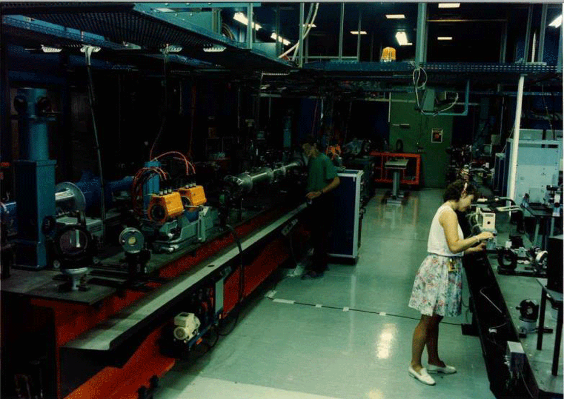
Figure 2. The 100 TW P102 laser system at CEA Limeil-Valenton, France (picture courtesy of CEA).

Figure 3. The Vulcan 100 TW laser from the early/mid-1990s showing the first ever single-pass CPA compressor system with one grating in air (centre) and the second in vacuum (bottom right) (picture courtesy of STFC Rutherford Appleton Laboratory).
The world’s first petawatt laser was put together in 1996 re-purposing one beamline of the existing Nova Nd:glass laser facility based at Lawrence Livermore National Laboratory (LLNL)[Reference Perry, Pennington, Stuart, Tietbohl, Britten, Brown, Herman, Golick, Kartz, Miller, Powell, Vergino and Yanovsky2]. It operated for three years and delivered 1.5 PW with energy up to 680 J to target. By applying chirped-pulse-amplification and stretching pulses from a new, Ti:sapphire based short pulse front-end tuned to 1053 nm centre wavelength to 1 ns, developing metre-scale diffraction gratings for the pulse compressor and using a reflective focusing configuration, the NOVA Petawatt (Figure 4) opened the door to a myriad of high intensity science exploration. In 2004 Vulcan became the first petawatt laser commissioned as a true user facility[Reference Danson, Brummitt, Clarke, Collier, Fell, Frackiewicz, Hancock, Hawkes, Hernandez-Gomez, Holligan, Hutchinson, Kidd, Lester, Musgrave, Neely, Neville, Norreys, Pepler, Reason, Shaikh, Winstone, Wyatt and Wyborn36] at the Central Laser Facility, Rutherford Appleton Laboratory, UK. The first multi-kJ facility, OMEGA-EP, was brought online at LLE in 2008, producing 2.1 kJ at 10 ps pulse duration[Reference Kelly, Waxer, Bagnoud, Begishev, Bromage, Kruschwitz, Kessler, Loucks, Maywar, McCrory, Meyerhofer, Morse, Oliver, Rigatti, Schmid, Stoeckl, Dalton, Folnsbee, Guardalben, Jungquist, Puth, Shoup, Weiner and Zuegel37]. It should be noted that, with the dawn of megajoule-scale Nd:glass lasers, these facilities are, in their own right, petawatt class lasers, albeit multi-beam facilities. The National Ignition Facility (NIF)[Reference Miller, Moses and West38], commissioned at LLNL in 2009, was originally specified to deliver 1.8 MJ in 3 ns, giving an output power of 400 TW. Details of all these facilities can be found in the geographical breakdown of current facilities in the next section of this review.

Figure 4. Inside the Nova Petawatt compressor chamber (picture courtesy of LLNL).
Following the development of the Ti:sapphire oscillator in 1991[Reference Spence, Kean and Sibbet27], extraordinary progress has been made with this medium. The first petawatt class Ti:sapphire laser was commissioned as early as 1999 in the US on the JanUSP system at LLNL. It was pumped by the 1970s JANUS Nd:glass laser and produced 200 TW in 85 fs initially. In Japan at the J-KAREN facility, they produced close to one petawatt (0.85 PW) in 2003[Reference Aoyama, Yamakawa, Akahane, Ma, Inoue, Ueda and Kiriyama39]. The next major milestone was the BELLA laser at Berkeley, where in 2013 it produced the first ever petawatt system operating at 1 Hz[Reference Leemans, Daniels, Deshmukh, Gonsalves, Magana, Mao, Mittelberger, Nakamura, Riley, Syversrud, Toth and Ybarrolaza40]. Only five years later the world’s first high average power petawatt laser system HAPLS[Reference Haefner, Bayramian, Betts, Bopp, Buck, Cupal, Drouin, Erlandson, Horáček, Horner, Jarboe, Kasl, Kim, Koh, Koubíková, Maranville, Marshall, Mason, Menapace, Miller, Mazurek, Naylon, Novák, Peceli, Rosso, Schaffers, Sistrunk, Smith, Spinka, Stanley, Steele, Stolz, Suratwala, Telford, Thoma, VanBlarcom, Weiss and Wegner41] developed at Lawrence Livermore National Laboratory was installed at the ELI-Beamlines facility in the Czech Republic. The laser uses a single-aperture, diode-pumped solid-state laser (DPSSL) to pump its Ti:sapphire medium and the laser is designed to deliver ${>}$
1 PW at 10 Hz, with a commissioning demonstration in 2018 of 0.5 PW at 3.3 Hz. In March 2019 Thales reported the first demonstration of 10 PW operation of their system installed at ELI-NP in Magurele, Romania[42]. Several other lasers of similar peak power performance are underway in China, France and the Czech Republic. Details of all these facilities are provided in the geographical breakdown of current facilities in this review.
${>}$
1 PW at 10 Hz, with a commissioning demonstration in 2018 of 0.5 PW at 3.3 Hz. In March 2019 Thales reported the first demonstration of 10 PW operation of their system installed at ELI-NP in Magurele, Romania[42]. Several other lasers of similar peak power performance are underway in China, France and the Czech Republic. Details of all these facilities are provided in the geographical breakdown of current facilities in this review.
The development of amplifiers capable of supporting broad bandwidths is also required to realize high-peak powers. Early systems relied entirely on dye or Nd:glass amplifiers. While dye lasers could support very large bandwidths, their short lifetimes and low saturation fluences severely limited the amount of energy that could be extracted. Neodymium-based lasers, on the other hand, could provide a large amount of energy but would support only a limited bandwidth. This led to the search for a new laser material that could provide the energy and bandwidth required to support high-energy short pulses. Ti:sapphire oscillators[Reference Moulton26] coupled with optical parametric amplification systems[Reference Dubietis, Jonus̆auskas and Piskarskas43] provided the solution for these problems. These were initially used in the pre-amplification stages of multi-terawatt systems in conjunction with Nd:glass rod or disc amplifiers. They provided many orders of magnitude of gain at high bandwidth before larger amplifiers, generally Nd:glass, added the last few orders and limited the reduction of the bandwidth. As the quality and size of available Ti:sapphire and nonlinear crystals have improved, so has the energy that can be extracted from these systems. An overview of the development of these systems is given in Section 4.1.1 covering ‘The journey to 100 PW OPCPA facilities’ later in this review.
1.3 Introduction – the future
For this review it was felt appropriate to not only give an historical perspective and the current status of facilities, but also to look to the future, about where facilities are going, and what these might look like in 10–20 years’ time. New petawatt laser facilities are embracing a new mission to establish operation of secondary source beamlines and attract users from a much broader range of research fields. A precursor to this approach was Laserlab-Europe, the integrated infrastructure initiative of European Laser Research Infrastructures[44] that provides access to laser facilities to plasma physicists as well as biologists, chemists and material scientists. This treats lasers in a very similar way to any other conventional beamline user facility, such as synchrotrons or particle accelerators.
Facilities, currently in their final commissioning phase, like the European Extreme Light Infrastructure (ELI) pillars in the Czech Republic, Romania and Hungary[45], are pushing forward this concept, providing user access not only to laser beamlines, but also to laser-produced secondary radiation and particle sources, including gamma-ray, proton and electron beams. Facilities currently in their conceptual development phase, like the European EuPRAXIA infrastructure[46] or the US k-BELLA facility[Reference Leemans47], aim at further advancing this concept, by incorporating step-like changes in the design to enable high-repetition-rate, accelerator-like, high-quality operation of the secondary sources, in a compact size and efficient mode of operation. In light of these developments, the later sections of the review therefore address three areas: ultra-high-power development; high-average-power development; and enabling technologies.
In the ultra-high-power development section we examine the journey to 100 PW OPCPA systems; other developments which could be used to achieve exawatt scale facilities and the potential use of plasma amplifiers as booster amplifiers for these systems.
The high-average-power developments deserve a special mention as they represent the key to the delivery of commercially relevant applications of petawatt lasers. Indeed, research with petawatt lasers has been prolific in terms of results with a high potential for applications in several areas, including medicine, materials and environmental sciences. This applies, for example, to secondary radiation sources for phase-contrast X-ray imaging[Reference Cole, Symes, Lopes, Wood, Poder, Alatabi, Botchway, Foster, Gratton, Johnson, Kamperidis, Kononenko, De Lazzari, Palmer, Rusby, Sanderson, Sandholzer, Sarri, Szoke-Kovacs, Teboul, Thompson, Warwick, Westerberg, Hill, Norris, Mangles and Najmudin48], for pulsed neutron imaging[Reference Roth, Jung, Falk, Guler, Deppert, Devlin, Favalli, Fernandez, Gautier, Geissel, Haight, Hamilton, Hegelich, Johnson, Merrill, Schaumann, Schoenberg, Schollmeier, Shimada, Taddeucci, Tybo, Wagner, Wender, Wilde and Wurden49] or for developments of therapy using very high energy radiation[Reference Moskvin, Subiel, Desrosiers, Wiggins, Maryanski, Mendonca, Boyd, Sorensen, Cipiccia, Issac, Welsh, Brunetti, Aniculaesei and Jaroszynski50, 51]. The delivery of industrial products in this context has so far been hindered by the lack of high-average-power sources capable of supporting continuous operation at the high repetition rate needed for such uses. Ongoing developments are changing this landscape, with new technologies such as diode laser pumping progressively replacing traditional flashlamp technology, opening the way to efficient and stable operation of petawatt laser-driven secondary radiation and particle sources. We therefore look at the development of new materials for HAP (high average power) technology; new OPCPA schemes; and coherent beam combining in fibre-based systems. This later section covers both spatially multiplexed and temporally multiplexed schemes.
In the final section we examine enabling technologies: where we are; the challenges facing us; and what we believe we will be able to achieve. This will include: the development of mid-IR lasers; the use of plasma optics; grand challenges that face the community in optics, diagnostics and target design; and the issue of temporal contrast techniques to improve the delivered pulse fidelity.
2 Geographic overview of facilities
In the section we give an overview of the current status of petawatt class lasers worldwide. Unlike the 2015 review paper, we have chosen to present this geographically. This was felt appropriate for two main reasons: firstly, the original paper sub-divided the lasers by their classification, but increasingly this is less clear to determine, as many systems are designed using mixed technologies; secondly it graphically illustrates the shift in time of the centre of gravity of ultra-high-intensity facilities from initially the US, through Europe, and currently firmly centred in Asia.
2.1 Geographic overview of facilities – North America
The US, with its combination of national laboratories and university-based systems, had the lead in ultra-high-power laser facilities worldwide until the start of the new millennium. These have ranged from: the first petawatt laser in Nova Petawatt; the only fully operational megajoule facility in NIF; pioneering university-based systems at the University of Rochester with OMEGA and its upgrade OMEGA-EP; and the BELLA facility at Lawrence Berkeley National Laboratory. The pioneering CPA technique also was developed at the University of Rochester. The following section describes the capabilities of these facilities and includes the Advanced Laser Light Source (ALLS) in Canada.
2.1.1 USA
Lawrence Livermore National Laboratory (LLNL) has played a critical and leading role in the development of high-energy and ultra-high-power laser facilities. The building blocks for Nd:glass lasers were developed at LLNL over many years and brought together to construct the Shiva facility in the late 1970s[Reference Speck, Bliss, Glaze, Herris, Holloway, Hunt, Johnson, Kuizenga, Ozarski, Patton, Rupert, Suski, Swift and Thompson52]. The successor laser, Nova, had one of its beamlines reconfigured in the late 1990s to deliver the first-ever petawatt laser worldwide[Reference Perry, Pennington, Stuart, Tietbohl, Britten, Brown, Herman, Golick, Kartz, Miller, Powell, Vergino and Yanovsky2]. A dedicated front end and vacuum compressor were used to deliver 680 J in a 440 fs pulse, giving 1.5 PW. One of the major developments for Nova Petawatt was the capability to manufacture large-aperture diffraction gratings, up to 1 m, for use in the vacuum compressor.
The NIF (National Ignition Facility)[Reference Miller, Moses and West38] at LLNL, is the first and currently the only fully operational megajoule scale facility. It has 192 $40~\text{cm}\times 40~\text{cm}$
beams that initially delivered a total of 1.8 MJ in a
$40~\text{cm}\times 40~\text{cm}$
beams that initially delivered a total of 1.8 MJ in a ${\sim}$
3 ns shaped pulse @ 3
${\sim}$
3 ns shaped pulse @ 3 $\unicode[STIX]{x1D714}$
, 0.6 PW (a true petawatt class laser in its own right, albeit delivered in multiple beamlines) configured for indirect beam drive. It became operational and officially dedicated in March 2009. The facility has been operational for over nine years and delivered data for both the NIC (National Ignition Campaign)[Reference Lindl, Landen, Edwards and Moses53] and the US stockpile stewardship programme. In 2018 NIF achieved a record of 2.15 MJ delivered to target, although without increase to the peak power[54].
$\unicode[STIX]{x1D714}$
, 0.6 PW (a true petawatt class laser in its own right, albeit delivered in multiple beamlines) configured for indirect beam drive. It became operational and officially dedicated in March 2009. The facility has been operational for over nine years and delivered data for both the NIC (National Ignition Campaign)[Reference Lindl, Landen, Edwards and Moses53] and the US stockpile stewardship programme. In 2018 NIF achieved a record of 2.15 MJ delivered to target, although without increase to the peak power[54].
At LLNL, NIF ARC (advanced radiographic capability)[Reference Barty, Key, Britten, Beach, Beer, Brown, Bryan, Caird, Carlson, Crane, Dawson, Erlandson, Fittinghoff, Hermann, Hoaglan, Iyer, Jones, Jovanovic, Komashko, Landen, Liao, Molander, Mitchell, Moses, Nielsen, Nguyen, Nissen, Payne, Pennington, Risinger, Rushford, Skulina, Spaeth, Stuart, Tietbohl and Wattellier55] is designed as an advanced X-ray radiography capability for NIF (Figure 5). NIF ARC uses four (one quad) of NIF’s beams to obtain a temporal resolution of tens of picoseconds and became operational in 2015. Each beam is split into two, producing eight petawatt class beams delivering between 0.4 and 1.7 kJ at pulse lengths between 1.3 and 38 ps (0.5 PW each) in the infrared. ARC drove many developments for kJ-short pulse lasers forward such as high-efficiency meter-scale dielectric gratings[Reference Britten, Molander, Komashko and Barty56], single shot precision diagnostics[Reference Haefner, Heebner, Dawson, Fochs, Shverdin, Crane, Kanz, Halpin, Phan, Sigurdsson, Brewer, Britten, Brunton, Clark, Messerly, Nissen, Shaw, Hackel, Hermann, Tietbohl, Siders and Barty57], and dispersion management[Reference Haefner, Hackel, Halpin, Crane, Messerly, Nissen, Shverdin, Shaw, Dawson, Siders and Barty58].
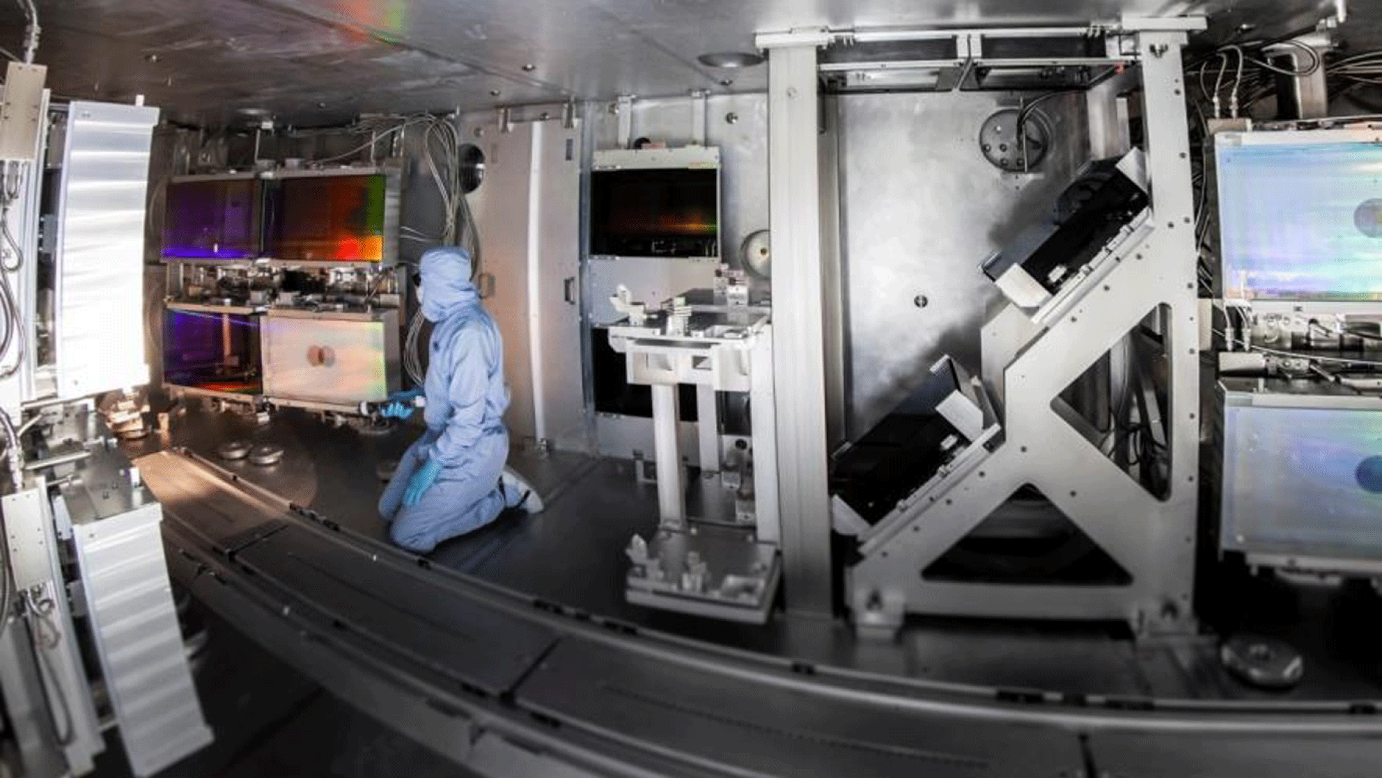
Figure 5. NIF ARC compressor gratings during final alignment (picture courtesy of LLNL).
Titan[Reference Stuart, Bonlie, Britten, Caird, Cross, Ebbers, Eckart, Erlandson, Molander, Ng, Patel and Price59] is one of five lasers that make up the Jupiter Laser Facility at LLNL. It is a petawatt class laser coupled to a kilojoule beamline for a broad range of experiments. The short pulse beamline delivers up to 300 J in a sub-picosecond pulse, and offers a 50 J high-contrast green option. It is currently being upgraded to higher peak power and a third beamline added.
There is a long history of using diode-pumped technology at LLNL originally with the Mercury laser facility, a diode-pumped Yb:S-FAP laser. Mercury was developed as a high-average-power laser (HAPL) using diode arrays for laser pumping and pioneered gas cooling as a precursor to an advanced fusion driver and was later considered for a potential pump laser for Ti:sapphire lasers[Reference Bayramian, Armstrong, Ault, Beach, Bibeau, Caird, Campbell, Chai, Dawson, Ebbers, Erlandson, Fei, Freitas, Kent, Liao, Ladran, Menapace, Molander, Payne, Peterson, Randles, Schaffers, Sutton, Tassano, Telford and Utterback60]. This was moth-balled and then dismantled to make way for HAPLS[Reference Haefner, Bayramian, Betts, Bopp, Buck, Cupal, Drouin, Erlandson, Horáček, Horner, Jarboe, Kasl, Kim, Koh, Koubíková, Maranville, Marshall, Mason, Menapace, Miller, Mazurek, Naylon, Novák, Peceli, Rosso, Schaffers, Sistrunk, Smith, Spinka, Stanley, Steele, Stolz, Suratwala, Telford, Thoma, VanBlarcom, Weiss and Wegner41], a 1 PW @ 10 Hz system generating ${>}$
30 J in 30 fs for ELI-Beamlines discussed later in this paper. The high-power diode array technology was jointly developed by LLNL and LaserTel. The LLNL team has successfully completed the construction of the all-diode-pumped HAPLS laser, and currently it is operated at the ELI-Beamlines in the Czech Republic as the L3 laser, with an initial repetition rate of 3.3 Hz to bring the target area up in steps.
${>}$
30 J in 30 fs for ELI-Beamlines discussed later in this paper. The high-power diode array technology was jointly developed by LLNL and LaserTel. The LLNL team has successfully completed the construction of the all-diode-pumped HAPLS laser, and currently it is operated at the ELI-Beamlines in the Czech Republic as the L3 laser, with an initial repetition rate of 3.3 Hz to bring the target area up in steps.
The Laboratory for Laser Energetics (LLE) at the University of Rochester, although university based, is operated more akin to a national laboratory. It has played a critical role in the development of ultra-high-power lasers, from the original development of CPA[Reference Strickland and Mourou16] to the first of the multi-kJ petawatt facilities, OMEGA-EP, to be operational. OMEGA-EP is a four-beam system with an architecture very similar to that of the NIF laser and is coupled with the well-proven 30 kJ at 351 nm, 60-beam long-pulse OMEGA laser system[Reference Kelly, Waxer, Bagnoud, Begishev, Bromage, Kruschwitz, Kessler, Loucks, Maywar, McCrory, Meyerhofer, Morse, Oliver, Rigatti, Schmid, Stoeckl, Dalton, Folnsbee, Guardalben, Jungquist, Puth, Shoup, Weiner and Zuegel37]. Two of the EP beams can be operated in short-pulse mode with an OPCPA front end to add high-energy, petawatt class laser performance to provide X-ray backlighting and proton radiography capabilities for inertial confinement fusion (ICF) experiments. The laser can operate between 0.6 and 100 ps, delivering almost 1 PW performance at best compression, and 1.25 to 2.3 kJ performance at pulse widths ${>}$
10 ps. It has driven the development of high-damage-threshold multi-layer dielectric gratings and their use in tiled geometry.
${>}$
10 ps. It has driven the development of high-damage-threshold multi-layer dielectric gratings and their use in tiled geometry.
At Sandia National Laboratory a large-scale kilojoule class petawatt facility provides X-ray radiographic capability to the Z-pinch facility. The laser facility uses Beamlet[Reference Van Wonterghem, Murray, Campbell, Speck, Barker, Smith, Browning and Behrendt61], which was the original prototype facility for NIF at LLNL that was decommissioned in 1998 before being transferred to Sandia and renamed Z-Beamlet[Reference Rambo, Smith, Porter, Hurst, Speas, Adams, Garcia, Dawson, Thurston, Wakefield, Kellogg, Slattery, Ives, Broyles, Caird, Erlandson, Murray, Behrendt, Neilsen and Narduzzi62]. The upgrading of the facility to Z-Petawatt[Reference Schwarz, Rambo, Geissel, Edens, Smith, Brambrink, Kimmel and Atherton63] provides enhanced radiographic capability. The beamline, which consists of an OPCPA front end and Nd:phosphate glass amplifiers, delivers 500 J in 500 fs. Updates on the capabilities of the Z-Backlighter facility in its two modes of operation can be found in references from 2016[Reference Schwarz, Rambo, Armstrong, Schollmeier, Smith, Shores, Geissel, Kimmel and Porter64, Reference Rambo, Schwarz, Schollmeier, Geissel, Smith, Kimmel, Speas, Shores, Armstrong, Bellum, Field, Kletecka and Porter65]. There are now two CPA modes of operation based on two different vacuum grating compressors. The beam directly out of the main amplifiers can deliver $100~\text{J}/500~\text{fs}$
(200 TW) with a standalone target chamber. The other compressor delivers a
$100~\text{J}/500~\text{fs}$
(200 TW) with a standalone target chamber. The other compressor delivers a $500~\text{J}/500~\text{fs}$
, 1 PW, beamline to a new standalone chamber called Chama. Other long pulse modes of operation are available and upgrade to the petawatt capabilities planned.
$500~\text{J}/500~\text{fs}$
, 1 PW, beamline to a new standalone chamber called Chama. Other long pulse modes of operation are available and upgrade to the petawatt capabilities planned.
2.1.2 LaserNet US
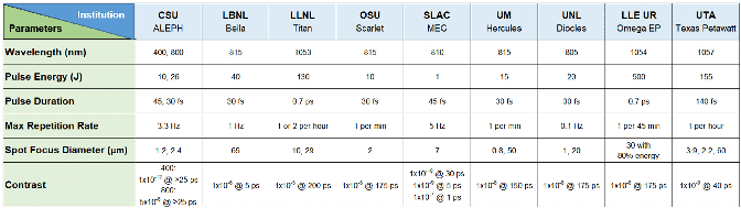
Given the numerous smaller-scale facilities in the USA (many described below) the DOE’s Office of Science has established a new coordination mechanism for institutes operating ultra-high-power lasers through LaserNet US. This network is designed to provide user access to petawatt class lasers and to foster collaborations. The initial members of LaserNet US are Colorado State University (CSU); Ohio State University (OSU); the Universities of Michigan (UM), Nebraska-Lincoln (UNL) and Texas (UT); the Stanford Linear Accelerator Center (SLAC); and Lawrence Berkeley National Laboratory (LBNL). The network was expanded in 2019 to include lasers from the Jupiter facility at LLNL and the OMEGA-EP at LLE, University of Rochester described above, both of which have already been operating as user facilities. A summary of the capabilities of these LaserNet US[66] facilities is given in Table 1.
Table 1. LaserNet US facility capabilities.
The Advanced Beam Laboratory at Colorado State University (CSU) operates a 0.85 PW Ti:sapphire laser operating at 3.3 Hz, with an option for second-harmonic operation at ultra-high contrast (Figure 6)[Reference Wang, Wang, Rockwood, Luther, Hollinger, Curtis, Calvi, Menoni and Rocca67]. The pump laser for the Ti:sapphire laser is a novel flashlamp-pumped high-repetition-rate Nd:glass amplifier. The beam propagates in a zigzag path in the amplifier gain medium, aided by total internal reflection in the polished wall of the slabs. Each slab amplifier generates pulses with ${\sim}$
18 J energy and 15 ns duration at 1053 nm, with a pulse energy fluctuation of
${\sim}$
18 J energy and 15 ns duration at 1053 nm, with a pulse energy fluctuation of ${\sim}$
1% RMS (root mean square). The amplified beams are frequency-doubled by LBO crystals to generate 11 J pulses at 527 nm to produce a total Ti:sapphire pump energy of 88 J. They have also developed a joule class, all-diode-pumped cryo-cooled Yb:YAG picosecond laser operating at a 0.5 kHz repetition rate[Reference Baumgarten, Pedicone, Bravo, Wang, Yin, Menoni, Rocca and Reagan68] – a technology that is being considered for future high-average-power petawatt class CPA/OPCPA laser pump sources[Reference Cole, Symes, Lopes, Wood, Poder, Alatabi, Botchway, Foster, Gratton, Johnson, Kamperidis, Kononenko, De Lazzari, Palmer, Rusby, Sanderson, Sandholzer, Sarri, Szoke-Kovacs, Teboul, Thompson, Warwick, Westerberg, Hill, Norris, Mangles and Najmudin48].
${\sim}$
1% RMS (root mean square). The amplified beams are frequency-doubled by LBO crystals to generate 11 J pulses at 527 nm to produce a total Ti:sapphire pump energy of 88 J. They have also developed a joule class, all-diode-pumped cryo-cooled Yb:YAG picosecond laser operating at a 0.5 kHz repetition rate[Reference Baumgarten, Pedicone, Bravo, Wang, Yin, Menoni, Rocca and Reagan68] – a technology that is being considered for future high-average-power petawatt class CPA/OPCPA laser pump sources[Reference Cole, Symes, Lopes, Wood, Poder, Alatabi, Botchway, Foster, Gratton, Johnson, Kamperidis, Kononenko, De Lazzari, Palmer, Rusby, Sanderson, Sandholzer, Sarri, Szoke-Kovacs, Teboul, Thompson, Warwick, Westerberg, Hill, Norris, Mangles and Najmudin48].
Figure 6. The Advanced Beam Laboratory at Colorado State University (picture courtesy of Colorado State University).
Figure 7. The BELLA laser facility, the world’s first 1 Hz petawatt laser (picture courtesy of Lawrence Berkeley National Laboratory).
The BELLA (BErkeley Lab Laser Accelerator) facility has been operational since 2013 and was built for dedicated experiments on laser plasma acceleration at Lawrence Berkeley National Laboratory, US (Figure 7). BELLA can operate at peak power levels of 1.3 PW with, at the time, a record-setting repetition rate of 1 Hz[Reference Leemans, Daniels, Deshmukh, Gonsalves, Magana, Mao, Mittelberger, Nakamura, Riley, Syversrud, Toth and Ybarrolaza40]. The Ti:sapphire laser was commercially built by Thales and has demonstrated exceptional pointing stability ( ${<}1.3~\unicode[STIX]{x03BC}\text{rad}$
RMS), shot-to-shot energy stability (
${<}1.3~\unicode[STIX]{x03BC}\text{rad}$
RMS), shot-to-shot energy stability ( ${<}$
1% RMS) and pulse duration stability (
${<}$
1% RMS) and pulse duration stability ( ${<}$
5% RMS). BELLA has demonstrated quasimonoenergetic electron beams of up to 7.8 GeV via laser-plasma wakefield acceleration using a capillary discharge gas target system[Reference Gonsalves, Nakamura, Daniels, Benedetti, Pieronek, de Raadt, Steinke, Bin, Bulanov, van Tilborg, Geddes, Schroeder, Tóth, Esarey, Swanson, Fan-Chiang, Bagdasarov, Bobrova, Gasilov, Korn, Sasorov and Leemans69]. BELLA has also begun construction of i-BELLA, where using an
${<}$
5% RMS). BELLA has demonstrated quasimonoenergetic electron beams of up to 7.8 GeV via laser-plasma wakefield acceleration using a capillary discharge gas target system[Reference Gonsalves, Nakamura, Daniels, Benedetti, Pieronek, de Raadt, Steinke, Bin, Bulanov, van Tilborg, Geddes, Schroeder, Tóth, Esarey, Swanson, Fan-Chiang, Bagdasarov, Bobrova, Gasilov, Korn, Sasorov and Leemans69]. BELLA has also begun construction of i-BELLA, where using an ${\sim}f/2$
parabola and a new target chamber, they plan to perform ion acceleration experiments at intensities around
${\sim}f/2$
parabola and a new target chamber, they plan to perform ion acceleration experiments at intensities around $10^{22}~\text{W}/\text{cm}^{2}$
. k-BELLA is a proposal for a multi-kW average power laser which would enable high-average-power demonstration experiments of the rapidly advancing laser-plasma accelerator technology; providing a stepping stone to a laser-driven collider. The system performance is planned to be 3 J at 1 kHz operating at 30 fs. So, although not necessarily within the scope of the review in terms of power (100 TW) this is an important system which will be a technology demonstrator for much higher power systems[Reference Leemans47].
$10^{22}~\text{W}/\text{cm}^{2}$
. k-BELLA is a proposal for a multi-kW average power laser which would enable high-average-power demonstration experiments of the rapidly advancing laser-plasma accelerator technology; providing a stepping stone to a laser-driven collider. The system performance is planned to be 3 J at 1 kHz operating at 30 fs. So, although not necessarily within the scope of the review in terms of power (100 TW) this is an important system which will be a technology demonstrator for much higher power systems[Reference Leemans47].
HERCULES (High Energy Repetitive CUos LasEr System) was constructed at the FOCUS Center and Center for Ultrafast Optical Science (CUOS), University of Michigan. In 2004 ultra-high intensities of up to $10^{22}~\text{W}/\text{cm}^{2}$
in a 45 TW laser could be generated using wavefront correction and an
$10^{22}~\text{W}/\text{cm}^{2}$
in a 45 TW laser could be generated using wavefront correction and an $f/0.6$
off-axis focusing parabola[Reference Bahk, Rousseau, Planchon, Chvykov, Kalintchenko, Maksimchuk, Mourou and Yanovsky70]. By adding a booster amplifier to the system, 300 TW operation was achieved at a 0.1 Hz repetition rate[Reference Yanovsky, Chvykov, Kalinchenko, Rousseau, Planchon, Matsuoka, Maksimchuk, Nees, Cheriaux, Mourou and Krushelnick71]. Recently, CUOS received funding for upgrading HERCULES to 500 TW. The upgraded pump lasers used for the third and fourth amplification stages of HERCULES are a 5 Hz Gaia 16 J laser and an Atlas 100 J system from Thales Optronique SA. CUOS also houses the lambda-cubed laser, a 500 Hz, 20 mJ, 30 fs laser, that is involved in developing high-repetition-rate electrons, X-rays and ion sources[Reference Hou, Nees, Easter, Davis, Petrov, Thomas and Krushelnick72].
$f/0.6$
off-axis focusing parabola[Reference Bahk, Rousseau, Planchon, Chvykov, Kalintchenko, Maksimchuk, Mourou and Yanovsky70]. By adding a booster amplifier to the system, 300 TW operation was achieved at a 0.1 Hz repetition rate[Reference Yanovsky, Chvykov, Kalinchenko, Rousseau, Planchon, Matsuoka, Maksimchuk, Nees, Cheriaux, Mourou and Krushelnick71]. Recently, CUOS received funding for upgrading HERCULES to 500 TW. The upgraded pump lasers used for the third and fourth amplification stages of HERCULES are a 5 Hz Gaia 16 J laser and an Atlas 100 J system from Thales Optronique SA. CUOS also houses the lambda-cubed laser, a 500 Hz, 20 mJ, 30 fs laser, that is involved in developing high-repetition-rate electrons, X-rays and ion sources[Reference Hou, Nees, Easter, Davis, Petrov, Thomas and Krushelnick72].
The Diocles laser at the Extreme Light Laboratory, University of Nebraska–Lincoln came online at a power level of 100 TW at 10 Hz in 2008, and 0.7 PW at 0.1 Hz in 2012[Reference Liu, Banerjee, Zhang, Chen, Brown, Mills, Powers, Zhao, Golovin, Ghebregziabher and Umstadter73]. It has been modified since to have active feedback spectral phase control[Reference Liu, Zhang, Chen, Golovin, Banerjee, Zhao, Powers, Ghebregziabher and Umstadter74], and then with a dual-compressor geometry[Reference Liu, Golovin, Chen, Zhang, Zhao, Haden, Banerjee, Silano, Karwowski and Umstadter75]. The group recently discovered multi-photon nonlinear Thomson scattering for generating X-rays[Reference Yan, Fruhling, Golovin, Haden, Luo, Zhang, Zhao, Zhang, Liu, Chen, Chen, Banerjee and Umstadter76]. The purpose-built research facility occupies three floors of the Behlen Laboratory Building and operates three separate and independent systems operating at: 0.7 PW peak power at 0.1 Hz; 100 TW at 10 Hz; and 6 TW at 10 Hz.
The Texas Petawatt Laser[Reference Gaul, Martinez, Blakeney, Jochmann, Ringuette, Hammond, Borger, Escamilla, Douglas, Henderson, Dyer, Erlandson, Cross, Caird, Ebbers and Ditmire77] based at the Texas Centre for High Intensity Laser Science at the University of Texas at Austin uses a high-energy OPCPA front end with optimized mixed glass to produce shorter pulses than traditional glass petawatt facilities. The OPCPA system amplifies pulses up to the joule level with broad bandwidth, followed by final amplification in mixed glass Nd:glass amplifiers. The first 64 mm rod is silicate with eight-pass angular multiplexing and then four-pass through two pairs of phosphate disc amplifiers. The 1.1 PW beamline produces a bandwidth of 14.6 nm, delivering 186 J in 167 fs. With an $f/1.1$
OAP and an active feedback deformable mirror, the pulses can achieve peak focal intensities up to
$f/1.1$
OAP and an active feedback deformable mirror, the pulses can achieve peak focal intensities up to $2\times 10^{22}~\text{W}/\text{cm}^{2}$
. In 2015 the front end was upgraded to improve contrast by implementing a picosecond OPCPA stage prior to full pulse stretching in order to reduce parametric fluorescence. Further improvements were made by moving away from lens-based telescopes to an all-reflective geometry, which eliminated a series of pre-pulses.
$2\times 10^{22}~\text{W}/\text{cm}^{2}$
. In 2015 the front end was upgraded to improve contrast by implementing a picosecond OPCPA stage prior to full pulse stretching in order to reduce parametric fluorescence. Further improvements were made by moving away from lens-based telescopes to an all-reflective geometry, which eliminated a series of pre-pulses.
The Scarlet laser facility[Reference Poole, Willis, Daskalova, George, Feister, Jiang, Snyder, Marketon, Schumacher, Akli, Van Woerkom, Freeman and Chowdhury78] at Ohio State University was built for studies on high-energy density physics and relativistic plasma physics in a dedicated climate and particulate controlled environment in the physics research building. The project began in 2007, with the facility becoming operational in 2012. The dual CPA (DCPA) front end is a kHz Femtopower system (Femtolasers) which goes through a contrast-enhanced cross polarized wave (XPW) process. The final output operates at 15 J in ${<}$
40 fs, achieving
${<}$
40 fs, achieving ${>}$
400 TW with a shot every minute. The Scarlet laser compressor chamber is vacuum isolated from its target chamber via a Brewster angle
${>}$
400 TW with a shot every minute. The Scarlet laser compressor chamber is vacuum isolated from its target chamber via a Brewster angle ${\sim}6~\unicode[STIX]{x03BC}\text{m}$
thick nitro-cellulose pellicle, and can achieve peak intensities up to
${\sim}6~\unicode[STIX]{x03BC}\text{m}$
thick nitro-cellulose pellicle, and can achieve peak intensities up to $8\times 10^{21}~\text{W}/\text{cm}^{2}$
. One of the main experimental focuses of the Scarlet facility is ion and electron acceleration from micron-structured targets[Reference Jiang, Ji, Audesirk, George, Snyder, Krygier, Poole, Willis, Daskalova, Chowdhury, Lewis, Schumacher, Pukhov, Freeman and Akli79].
$8\times 10^{21}~\text{W}/\text{cm}^{2}$
. One of the main experimental focuses of the Scarlet facility is ion and electron acceleration from micron-structured targets[Reference Jiang, Ji, Audesirk, George, Snyder, Krygier, Poole, Willis, Daskalova, Chowdhury, Lewis, Schumacher, Pukhov, Freeman and Akli79].
The LCLS (Linac Coherent Light Source) is one of the principal facilities at the SLAC National Accelerator Laboratory. The MEC (Materials in Extreme Conditions) instrument combines the unique LCLS coherent X-ray beamline with a femtosecond laser system. This system has been operational at the 25 TW level, but is planned to be upgraded to the petawatt class level.
2.1.3 Canada
At the University of Quebec, Montreal, Canada the Advanced Laser Light Source (ALLS) is a commercial Ti:sapphire PULSAR system built by Amplitude Technologies operating at 200 TW (5 J, 20 fs, 5–10 Hz PULSAR laser)[Reference Formaux, Payeur, Alexandrov, Serbanescu, Martin, Ozaki, Kudryashov and Kieffer80]. The system has recently been upgraded to deliver 500 TW (10 J, 20 fs)[81].
2.2 Geographic overview of facilities – Europe
Europe has been pivotal in the development of ultra-high-intensity lasers, with many systems operational in both national laboratories and universities. Many of the developments necessary for the advancement of these systems, including OPCPA, were pioneered in Europe. There is a very strong industrial base, in France in particular, which supplies components, subsystems and even petawatt class facilities to laboratories throughout the world. Looking to the future, ELI (Extreme Light Infrastructure) is a distributed European infrastructure comprising three pillars situated in the Czech Republic, Romania and Hungary, and financed through European Union structural funds. These facilities will transform how researchers gain access to world-leading interaction capabilities, with all three facilities due to start operations in 2019.
Europe has also benefited from the coordination role provided by Laserlab-Europe, bringing together researchers from 38 organizations, as full members, from 16 countries. Its main objective is to provide a sustainable interdisciplinary network of European laser laboratories to: provide training in key areas; conduct research into areas of perceived bottlenecks; and offer access to many of the member facilities to perform world-class research.
2.2.1 United Kingdom
The UK has two national laboratories with facilities which generate ultra-high powers: the STFC Rutherford Appleton Laboratory, which hosts the Central Laser Facility (CLF); and the Atomic Weapons Establishment (AWE). There are also very active programmes within UK Universities, with petawatt class lasers at the University of Strathclyde and Queen’s University Belfast.
Vulcan at the STFC Rutherford Appleton Laboratory was the first petawatt class laser to be used by the international plasma physics community as a dedicated user facility. It is a high-power Nd:glass laser[Reference Danson, Brummitt, Clarke, Collier, Fell, Frackiewicz, Hancock, Hawkes, Hernandez-Gomez, Holligan, Hutchinson, Kidd, Lester, Musgrave, Neely, Neville, Norreys, Pepler, Reason, Shaikh, Winstone, Wyatt and Wyborn36] which has been operational for over 40 years. It enables a broad range of experiments through a flexible geometry[Reference Hernandez-Gomez, Brummitt, Canny, Clarke, Collier, Danson, Dunne, Fell, Frackiewicz, Hancock, Hawkes, Heathcote, Holligan, Hutchinson, Kidd, Lester, Musgrave, Neely, Neville, Norreys, Pepler, Reason, Shaikh, Winstone and Wyborn82, Reference Musgrave, Boyle, Carroll, Clarke, Heathcote, Galimberti, Green, Neely, Notley, Parry, Shaikh, Winstone, Pepler, Kidd, Hernandez-Gomez and Collier83]. It has two target areas: one with six 300 J (1053 nm at 1 ns) long-pulse beamlines combined with two synchronized short-pulse beams and a separate target area with high-energy petawatt capability (500 J in 500 fs) synchronized with a single long-pulse beamline.
The Vulcan Petawatt target area will undergo an upgrade with the addition of a petawatt class OPCPA-based beamline delivering pulses with 30 J and 30 fs with a centre wavelength of 880 nm. A new laser area will be created that houses a front end based on a DPSSL-pumped picosecond OPCPA scheme whereby the output from a Ti:sapphire oscillator is amplified to the millijoule level in LBO. These pulses are then stretched to 3 ns before undergoing further stages of amplification in LBO, the final stage employing one of the Vulcan long-pulse beamlines as a pump laser. The pulses will then be compressed in the target area and focused into the same target chamber as the existing petawatt beamline.
The Vulcan 2020 upgrade project is a proposal to increase the peak power of Vulcan to 20 PW (400 J and 20 fs), to enhance its long-pulse capability and to introduce a new target area for interactions at extremely high intensities. The peak power will be increased by the installation of an OPCPA beamline using DKDP crystals pumped by two dedicated 1.5 kJ Nd:glass lasers. The long-pulse provision will be increased by the use of additional 208 mm aperture Nd:glass amplifiers, increasing the output energy of each of the six long-pulse beams to ${\sim}$
2 kJ per beam[Reference Hernandez-Gomez, Blake, Chekhlov, Clarke, Dunne, Galimberti, Hancock, Heathcote, Holligan, Lyachev, Matousek, Musgrave, Neely, Norreys, Ross, Tang, Winstone, Wyborn and Collier84].
${\sim}$
2 kJ per beam[Reference Hernandez-Gomez, Blake, Chekhlov, Clarke, Dunne, Galimberti, Hancock, Heathcote, Holligan, Lyachev, Matousek, Musgrave, Neely, Norreys, Ross, Tang, Winstone, Wyborn and Collier84].
Gemini is a Ti:sapphire laser system[Reference Hooker, Collier, Chekhlov, Clarke, Divall, Ertel, Foster, Hancock, Hawkes, Holligan, Langley, Lester, Neely, Parry and Wyborn85] operated within the Central Laser Facility. It is operated as an academic user facility that in recent years has seen an increase in the number of industrially focused experiments requested. It has two ultra-high-power beamlines, each delivering 15 J in 30 fs pulses @ 800 nm, giving 500 TW beams to target, generating focused intensities ${>}10^{21}~\text{W}/\text{cm}^{2}$
. Routine high-contrast operation can be achieved with the use of a double plasma mirror assembly within the target chamber.
${>}10^{21}~\text{W}/\text{cm}^{2}$
. Routine high-contrast operation can be achieved with the use of a double plasma mirror assembly within the target chamber.
AWE, Aldermaston operates the Orion facility which became operational in April 2013 (Figure 8). It is a Nd:glass laser system which combines 10 long-pulse beamlines (500 J, 1 ns @ 351 nm) with two synchronized infrared petawatt beams (500 J in 500 fs)[Reference Hopps, Oades, Andrew, Brown, Cooper, Danson, Daykin, Duffield, Edwards, Egan, Elsmere, Gales, Girling, Gumbrell, Harvey, Hillier, Hoarty, Horsfield, James, Leatherland, Masoero, Meadowcroft, Norman, Parker, Rothman, Rubery, Treadwell, Winter and Bett86]. One of the petawatt beamlines is operated in ultra-high-contrast mode by frequency doubling two square 300 mm sub-apertures to operate in the green, giving 200 J in ${<}$
500 fs, 400 TW, with nanosecond contrast levels of
${<}$
500 fs, 400 TW, with nanosecond contrast levels of ${>}10^{18}$
[Reference Parker, Danson, Egan, Elsmere, Girling, Harvey, Hillier, Hussey, Masoero, McLoughlin, Penman, Treadwell, Winter and Hopps87].
${>}10^{18}$
[Reference Parker, Danson, Egan, Elsmere, Girling, Harvey, Hillier, Hussey, Masoero, McLoughlin, Penman, Treadwell, Winter and Hopps87].
Figure 8. The Orion laser facility (picture courtesy of AWE).
The TARANIS (Terawatt Apparatus for Relativistic and Nonlinear Interdisciplinary Science) laser in the Centre for Plasma Physics in Queen’s University Belfast is a Nd:glass system that can deliver up to 30 J in a nanosecond to ${\sim}$
10 J in
${\sim}$
10 J in ${<}$
1 ps. TARANIS-X is a major upgrade based around OPCPA to provide
${<}$
1 ps. TARANIS-X is a major upgrade based around OPCPA to provide ${\sim}$
3 J in sub-10 fs pulses representing an ultimate specification of 300 TW in a single beam. The key aim of this upgrade is to improve the near-time contrast of the laser system while at the same time opening the way for few-cycle laser–matter interactions and investigations at relativistic intensities. The unique architecture of TARANIS/TARANIS-X will offer a suite of low- to high-power pulses with durations ranging from a few femtoseconds to nanoseconds, and repetition rates ranging from kHz to once every 10 min, respectively.
${\sim}$
3 J in sub-10 fs pulses representing an ultimate specification of 300 TW in a single beam. The key aim of this upgrade is to improve the near-time contrast of the laser system while at the same time opening the way for few-cycle laser–matter interactions and investigations at relativistic intensities. The unique architecture of TARANIS/TARANIS-X will offer a suite of low- to high-power pulses with durations ranging from a few femtoseconds to nanoseconds, and repetition rates ranging from kHz to once every 10 min, respectively.
University of Strathclyde, Glasgow is home to SCAPA (Scottish Centre for the Application of Plasma-based Accelerators), who operate a commercial Thales Ti:sapphire system commissioned in 2017 (Figure 9). It has 350 TW peak power (8.75 J, 25 fs per pulse) operating at 5 Hz, so with 44 W average power after compression it is currently Europe’s highest average power commercial petawatt-scale laser. The front end and vacuum compressor are compatible with an upgrade to petawatt peak power. The laser is used to drive up to four laser-plasma accelerator beamlines: two underdense for GeV-scale wakefield electrons; and two for solid target 50 MeV-scale proton/ion beams. One of the main centre goals is research into coherent radiation production[Reference Jaroszynski, Ersfeld, Islam, Brunetti, Shanks, Grant, Tooley, Grant, Reboredo Gil, Lepipas, McKendrick, Cipiccia, Wiggins, Welsh, Vieux, Chen, Aniculaesei, Manahan, Anania, Noble, Yoffe, Raj, Subiel, Yang, Sheng, Hidding, Issac, Cho and Hur88].
2.2.2 France
France has played an important role in the development, construction and operation of ultra-high-power laser facilities in its national laboratories, both academic and defence, and in its universities. A particular strength within France is having a very strong manufacturing base for all aspects of lasers, from components, advanced optics, subsystems and even full-scale petawatt class laser facilities, most notably from Thales and Amplitude Technologies.
At CEA CESTA (Centre d’etudes scientific d’Aquitaine), Bordeaux LMJ (Laser Megajoule), a megajoule class laser, is currently being commissioned[Reference Ebrardt and Chaput89]. The facility is designed with 176 long-pulse beams with apertures of $40~\text{cm}\times 40~\text{cm}$
, delivering a total energy of 1.4 MJ @ 351 nm with a maximum power of 400 TW. Five bundles (40 beams) were operational in 2018, with the rest of the beamlines being commissioned over the following years[Reference Nicolaizeau and Vivini90].
$40~\text{cm}\times 40~\text{cm}$
, delivering a total energy of 1.4 MJ @ 351 nm with a maximum power of 400 TW. Five bundles (40 beams) were operational in 2018, with the rest of the beamlines being commissioned over the following years[Reference Nicolaizeau and Vivini90].

Figure 9. The SCAPA facility at the University of Strathclyde (picture courtesy of University of Strathclyde).
A short-pulse capability is also available in LMJ through the PETAL multi-kilojoule glass beamline[Reference Blanchot, Behar, Berthier, Bignon, Boubault, Chappuis, Coïc, Damiens-Dupont, Ebrardt, Gautheron, Gibert, Hartmann, Hugonnot, Laborde, Lebeaux, Luce, Montant, Noailles, Néauport, Raffestin, Remy, Roques, Sautarel, Sautet, Sauteret and Rouyer91], which is coupled and synchronized to the long pulses. It uses four independent compressors with the beams phased together. The beamline is specified to operate at 3.5 kJ and was initially commissioned in 2015 with demonstrated performance at 1.15 PW, 700 fs in 850 J[Reference Blanchot, Béhar, Chapuis, Chappuis, Chardavoine, Charrier, Coïc, Damiens-Dupont, Duthu, Garcia, Goossens, Granet, Grosset-Grange, Guerin, Hebrard, Hilsz, Lamaignere, Lacombe, Lavastre, Longhi, Luce, Macias, Mangeant, Mazataud, Minou, Morgaint, Noailles, Neauport, Patelli, Perrot-Minnot, Present, Remy, Rouyer, Santacreu, Sozet, Valla and Laniesse92]. The performance will be increased when higher-damage-threshold transport optics is deployed. Following an agreement between CEA and the Region Aquitaine, 20%–30% of the time on LMJ/PETAL will be dedicated to academic research access[93]. In 2017 the first academic campaigns were conducted using both PETAL and the available LMJ long-pulse beams.
Laboratoire de l’Accélérateur Linéaire (LAL), Orsay University is host to the LASERIX facility[Reference Ros, Cassou, Cros, Daboussi, Demailly, Guilbaud, Kazamias, Lagron, Maynard, Neveu, Pittman, Zielbauer, Zimmer, Kuhl, Lacombe, Porcel, duPenhoat, Zeitoun and Mourou94]. A Ti:sapphire system originally at the University Paris Sud and transferred to LAL, was designed to be a high-repetition-rate multi-beam laser to pump an XUV laser. The laser performance was first demonstrated in 2006, delivering 36 J of energy, although without full compression[Reference Ple, Pittman, Jamelot and Chambaret95]. The system is currently operating at low-power mode (30 TW maximum) to pursue experiments with synchronized coherent X-rays with EUV and IR laser sources. It is expected that the facility will return to full operations in 2020/2021. LASERIX is currently being used as a high-intensity laser coupled with an electron gun, producing synchronized photoelectron bunches in the 5–10 MeV range. A plasma accelerating stage, which will be excited by an amplified pulse from LASERIX in order to reach the 100 MeV range, is being implemented.
Apollon at Orme de Merisiers, Saclay is a next-generation Ti:sapphire 10 PW facility (Figure 10)[Reference Papadopoulos, Zou, Le Blanc, Chériaux, Georges, Druon, Mennerat, Ramirez, Martin, Fréneaux, Beluze, Lebas, Monot, Mathieu and Audebert96]. The system is a hybrid OPCPA and Ti:sapphire system, pumped by Nd:glass systems supplied by Thales and Amplitude Technologies to realize short pulses at high energy with a high-contrast front end[Reference Papadopoulos, Ramirez, Genevrier, Ranc, Lebas, Pellegrina, LeBlanc, Monot, Martin, Zou, Mathieu, Audebert, Georges and Druon97]. The system is specified to deliver 150 J pulses at 15 fs, giving powers of 10 PW, at a shot rate of one shot per minute. There are two main beamlines delivering 1 PW and 10 PW pulses and two secondary beamlines delivering a 10 TW probe beam and a nanosecond uncompressed beam with energy up to 250 J. All four beam lines can be alternatively directed to two independent experimental areas for high-intensity interactions on either solid or gas targets. Apollon has recently demonstrated[Reference Papadopoulos, Zou, Le Blanc, Ranc, Druon, Martin, Fréneaux, Beluze, Lebas, Chabanis, Bonnin, Accary, Garrec, Mathieu and Audebert98] operation at the 1 PW level, with the first commissioning experiments scheduled at the beginning of 2019. The output power of the facility is planned to increase to 4 PW before the end of 2019 (with a 200 J pump) and 9 PW in 2020 (with an upgraded 500 J pump), and finally to 10 PW (with the 600 J designed pump system).
Figure 10. The Apollon laser at Orme des Merisiers (picture courtesy of Apollon).
At the Laboratoire d’Optique Appliquee (LOA), Palaiseau there is a commercial 200 TW Ti:sapphire laser delivering 6 J in 30 fs at 1 Hz, originally used as a proton source for medical applications but now used as a multi-particle accelerator for a broader range of applications.
2.2.3 Germany
Many of the laser facilities based in Germany have been brought under the umbrella of the Helmholtz Association. The Association was formed in 2001 and brings together 18 Helmholtz Centres in a broad range of scientific disciplines. The exceptions to this are the lasers operated at CALA in Garching and at the Institute for Laser and Plasma Physics in Dusseldorf. These facilities are described in detail below.
CALA (Centre for Advanced Laser Applications) in Garching is an institute run jointly by the Technical University of Munich (TUM) and the Ludwig Maximilian University of Munich (LMU). It operates the following two lasers.
∙ ATLAS 3000 consists of a homebuilt 300 TW peak power Ti:sapphire laser and a subsequent 90 J, 1 Hz power amplifier provided by Thales. After compression it is expected to deliver 60 J, 25 fs, 2.4 PW pulses at 1 Hz. The laser serves up to four experimental beamlines for laser-driven electron & ion acceleration; the former also constitutes the basis for well-controlled X-ray sources by undulatory radiation, betatron radiation, and Thomson backscattering in the energy range from keV to multi-MeV. A high-field beam line is available for laser-driven nuclear physics and high-field QED studies.
∙ The Petawatt Field Synthesizer (PFS), originally based at the Max-Planck-Institute for Quantenoptik (MPQ), in Garching is a 1 ps, 1 J, 10 Hz diode-pumped thick disk Yb:YAG laser used for pumping a few-cycle OPA chain with unprecedented temporal contrast[Reference Kessel, Leshchenko, Jahn, Krüger, Münzer, Schwarz, Pervak, Trubetskov, Trushin, Krausz, Major and Karsch99]. The system, now at CALA, is currently being upgraded to 10 J pump energy at 10 Hz. PFS-pro is a 5 kHz, 200 mJ, 1 ps thin-disk laser, originally intended to pump an OPA chain analogously to PFS (hence the name), but currently examines direct self-phase-modulation (SPM) broadening schemes to create ultra-short pulses for driving a Thomson X-ray source at high efficiency.
At The Institute for Laser and Plasma Physics, Heinrich-Heine University, Dusseldorf, Germany is the Arcturus system[Reference Cerchez, Prasad, Aurand, Giesecke, Spickermann, Brauckmann, Aktan, Swantusch, Toncian, Toncian and Willi100]. This is a two-beam Ti:sapphire system where the pulses in each beamline are compressed to ${\sim}$
30 fs and transported onto the interaction chamber with
${\sim}$
30 fs and transported onto the interaction chamber with ${\sim}$
50% efficiency. Both pulses can be spatially overlapped and temporally synchronized onto the target. Thus, the system can deliver
${\sim}$
50% efficiency. Both pulses can be spatially overlapped and temporally synchronized onto the target. Thus, the system can deliver $2\times 3.5~\text{J}=7~\text{J}$
energy onto the target within a pulse duration of 30 fs, giving a total system power onto target exceeding 200 TW.
$2\times 3.5~\text{J}=7~\text{J}$
energy onto the target within a pulse duration of 30 fs, giving a total system power onto target exceeding 200 TW.
The following is a summary of the facilities based at the Helmholtz Centres.
The PHELIX (Petawatt High Energy Laser for heavy Ion eXperiments) kilojoule glass laser system[Reference Bagnoud, Aurand, Blazevic, Borneis, Bruske, Ecker, Eisenbarth, Fils, Frank, Gaul, Goette, Haefner, Hahn, Harres, Heuck, Hochhaus, Hoffmann, Javorková, Kluge, Kuehl, Kunzer, Kreutz, Merz-Mantwill, Neumayer, Onkels, Reemts, Rosmej, Roth, Stoehlker, Tauschwitz, Zielbauer, Zimmer and Witte101] was constructed at the Helmholtz Centre GSI and is used either in stand-alone or in conjunction with a heavy ion accelerator. The laser can be switched between long- and short-pulse operation and in short-pulse mode is designed to deliver 400 J in 400 fs. Another kilojoule glass laser system is planned at GSI for the Helmholtz Beamline at FAIR (Facility for Antiproton and Ion Research). A repetition rate of one shot per minute is envisioned.
There are two diode-pumped systems POLARIS and PEnELOPE.
∙ POLARIS (Petawatt Optical Laser Amplifier for Radiation Intensive experiments) is based at the Helmholtz Institute Jena. It is designed as a fully diode-pumped Yb:glass/Yb:CaF $_{2}$
petawatt class laser[Reference Hornung, Liebetrau, Keppler, Kessler, Hellwing, Schorcht, Becker, Reuter, Polz, Körner, Hein and Kaluza102]. It operates at a central wavelength of 1030 nm with a bandwidth of 18 nm, allowing 98 fs pulse width after compression. The tiled grating compressor limits the peak power on target to about 200 TW, whereas amplification to 54 J has already been demonstrated.
$_{2}$
petawatt class laser[Reference Hornung, Liebetrau, Keppler, Kessler, Hellwing, Schorcht, Becker, Reuter, Polz, Körner, Hein and Kaluza102]. It operates at a central wavelength of 1030 nm with a bandwidth of 18 nm, allowing 98 fs pulse width after compression. The tiled grating compressor limits the peak power on target to about 200 TW, whereas amplification to 54 J has already been demonstrated.∙ PEnELOPE (Petawatt, Energy-Efficient Laser for Optical Plasma Experiments) is a rep-rated diode-pumped laser using broadband Yb:glass/Yb:CaF
$_{2}$
under construction at the Helmholtz-Zentrum Dresden-Rossendorf Laboratory within the ELBE Center (Electron Linac for beams with high Brilliance and low Emittance) for high-power radiation sources[Reference Siebold, Roeser, Loeser, Albach and Schramm103]. It will be dedicated to the production of laser accelerated proton and ion beams with energies
${>}$
100 MeV, relevant to future cancer treatments. The facility will deliver pulses of 150 J in 150 fs, giving
${>}$
1 PW at 1 Hz centred at 1030 nm, with testing of one of the main amplifiers recently demonstrated[Reference Albach, Loeser, Siebold and Schramm104].


There are also a number of commercial Ti:sapphire lasers based at Helmholtz Centres.
∙ DRACO (Dresden laser acceleration source)[Reference Zeil, Kraft, Bock, Bussmann, Cowan, Kluge, Metzkes, Richter, Sauerbrey and Schramm105] at the Helmholtz-Zentrum Dresden-Rossendorf Laboratory is a commercially sourced Ti:sapphire laser supplied by Amplitude Technologies. The facility is designed to investigate electron, ion and proton acceleration schemes for radiation therapy as part of the ELBE Center. It is operating at 150 TW at 10 Hz and 1 PW at 1 Hz.
∙ The commercial Ti:sapphire Jeti200 laser facility at the Helmholtz Institute Jena delivers 17 fs pulses with an energy of up to 5.6 J. The 300 TW system with ultra-high contrast is dedicated to plasma physics and particle acceleration experiments.
∙ The LUX group at the Center of Free-Electron Laser Science, Department of Physics, University of Hamburg operates a 200 TW commercial Ti:sapphire laser system ANGUS. The 25 fs pulses produced at a repetition rate of 5 Hz are used for the investigation of plasma accelerators and plasma-driven undulator X-ray generation[Reference Delbos, Werle, Dornmair, Eichner, Hübner, Jalas, Jolly, Kirchen, Leroux, Messner, Schnepp, Trunk, Walker, Winkler and Maier106].
∙ There is also a 300 TW, 25 fs Ti:sapphire Amplitude Technologies laser currently being constructed for HIBEF (Helmholtz International Beamline for Extreme Fields) at the European XFEL, DESY, Hamburg. The HED (high energy density) end station will couple the XFEL output with laser sources for ultra-intense laser applications[107].
2.2.4 Russia
The first operational petawatt class OPCPA system was developed at the Institute of Applied Physics, Russian Academy of Science (RAS), Nizhny Novgorod using a homemade pump beam. The laser delivered 0.2 PW in 2006[Reference Lozhkarev, Freidman, Ginzburg, Katin, Khazanov, Kirsanov, Luchinin, Mal’shakov, Martyanov, Palashov, Poteomkin, Sergeev, Shaykin and Yakovlev108] and was upgraded to 0.56 PW in 2007[Reference Lozhkarev, Freidman, Ginzburg, Katin, Khazanov, Kirsanov, Luchinin, Mal’shakov, Martyanov, Palashov, Poteomkin, Sergeev, Shaykin and Yakovlev109]. The facility known as PEARL (PEtawatt pARametric Laser) had active elements of DKDP; a wavelength of 910 nm; with pulse durations 43–45 fs. PEARL-X is the next generation of OPCPA facility, with a theoretical limit of 10 PW, but with a more realistic operating limit of 4–5 PW. The technology was also transferred to FEMTA at the Russian Federal Nuclear Center, Sarov, Nizhny Novgorod, using a 2 kJ laser for pumping. This was a potential multi-PW system, but constraints in the pump limited the output to 1 PW, 100 J in 100 fs.
The construction of a high-power megajoule laser facility was started in Russian Federal Nuclear Center, VNIIEF, Sarov, Nizhny Novgorod in 2012 with commissioning expected in the next few years[Reference Rozanov, Gus’kov, Vergunova, Demchenko, Stepanov, Doskoch, Yakhin, Bel’kov, Bondarenko and Zmitrenko110]. The multi-beam Nd:glass facility is designed to deliver 2.8 MJ of energy at 527 nm for inertial confinement fusion (ICF) direct drive target illumination. The target bay, which contains the 10-m-diameter spherical chamber, has two laser bays on either side. The facility has 192 Nd:phosphate glass laser beams, in a four-pass geometry, with each beam delivering 12.5 kJ at the second harmonic, a significant design difference from NIF or LMJ described elsewhere in this review (operating at the third harmonic). An adaptive system, based on deformable mirrors, will allow compensation of large-scale nonuniformities of laser beams. Unlike NIF or LMJ, where a cylindrical indirect drive geometry is used, at the VNIIEF facility scientists will use a spherical indirect drive target geometry. This uses six laser entrance holes, which achieves a very uniform X-ray field distribution on the surface of a DT ice cryogenic target.
2.2.5 Spain
At the Centre for Pulsed Lasers (CLPU), University of Salamanca VEGA is a user facility open for domestic and international researchers (Figure 11). The system is a custom-made Ti:sapphire laser from Amplitude Technologies[Reference Roso111]. There are three amplification lines, which share the same front end (XPW and Double CPA): VEGA-1 0.6 J, 20 TW at 10 Hz; VEGA-2 6 J, 200 TW at 10 Hz; and VEGA-3 30 J, 1 PW at 1 Hz[Reference Roso112]. The facility was officially inaugurated by the King of Spain in September 2018.

Figure 11. The VEGA 3 laser facility at the University of Salamanca (picture courtesy of the University of Salamanca).
2.2.6 Italy
In Italy two laboratories have commercial PULSAR Ti:sapphire laser systems from Amplitude Technologies, delivering 200 TW (5 J, 20 fs, 5–10 Hz)[Reference Gizzi, Benedetti, Alberto Cecchetti, Di Pirro, Gamucci, Gatti, Giulietti, Giulietti, Koester, Labate, Levato, Pathak and Piastra113].
∙ The Laboratori Nazionali di Frascati (LNF) is one of the four main laboratories of INFN (National Institute for Nuclear Physics). LNF has also addressed dedicated R&D on advanced accelerator concepts. Born from the integration of a high-brightness photo-injector (SPARC) and of a high-power laser (FLAME); SPARC_LAB is mainly devoted to conducting further development, characterization and application of compact radiation sources (FEL, THz, Compton) driven by plasma-based accelerator modules. This will investigate the techniques of: LWFA (laser wakefield acceleration), which uses short-pulse laser drivers to excite the wake; and PWFA (plasma wakefield acceleration), which uses a high-energy particle bunch to excite the wake[Reference Leemans47].
∙ The Intense Laser Irradiation Laboratory (ILIL), CNR (Consiglio Nazionale delle Ricerche) National Institute of Optics, Pisa was established in 2001 following more than a decade of experimental activity in the field of high-power laser–plasma interaction, also as a founding member of European collaboration programmes in the field, pioneering access to large-scale facilities and hosting Training Network activities. Today the laboratory is an active member of the Italian Extreme Light Infrastructure initiative and a partner of the EuPRAXIA H2020 collaboration (see 2.2.8) and is also an associate partner of the Eurofusion consortium. ILIL operates a Ti:sapphire laser for laser-driven light ion acceleration, currently operating at the
${\sim}$
150 TW level (4 J, 25 fs after compression), with plans to go to
${>}$
5 J, 25 fs[Reference Gizzi, Giove, Altana, Brandi, Cirrone, Cristoforetti, Fazzi, Ferrara, Fulgentini, Koester, Labate, Lanzalone, Londrillo, Mascali, Muoio, Palla, Schillaci, Sinigardi, Tudisco and Turchetti114]. The laboratory features active research programmes on laser-plasma electron acceleration, laser-driven light ion acceleration, and atmospheric propagation of intense laser pulses, and has long-standing expertise in medical applications of laser-driven radiation and particle sources[51].


2.2.7 Romania
At the Centre for Advanced Laser Technologies INFLPR (National Institute for Laser, Plasma and Radiation Physics), Măgurele, Romania the CETAL Ti:sapphire laser is a commercial petawatt laser (25 J in 25 fs at 0.1 Hz) supplied by Thales Optronics[115]. The laser system allows two modes of operation: 1 PW @ 0.1 Hz and 45 TW @ 10 Hz.
2.2.8 Multi-national European programmes
ELI (Extreme Light Infrastructure) is a distributed European infrastructure comprising three pillars situated in the Czech Republic, Romania and Hungary. ELI[46] will provide a unique platform for users of ultra-high-power lasers, with each facility providing multiple laser systems delivered to multiple dedicated target interaction areas. The facilities will be operated through a combined multi-national management structure known as ERIC (European Research Infrastructure Consortium). All three facilities are due to be online to users in 2019, with the first systems using kHz lasers going online first in a user-supported commissioning mode.
∙ ELI-Beamlines, Dolni Brezany, Czech Republic will provide a range of laser systems for research, not only in the fields of physics and material science, but also in biomedical research and laboratory astrophysics. The beamlines use lasers based on either OPCPA, Ti:sapphire, or a combination of the two to produce pulses ranging from hundreds of millijoules at a kHz up to a kJ beamline (flashlamp pumped mixed Nd-doped glass) firing once a minute. These will be coupled to separate interaction areas or beamlines, allowing a wide range of experiments to be performed. The laser systems are: L1:
$100~\text{mJ}/1~\text{kHz}$
; L2:
$1~\text{PW}/20~\text{J}/10~\text{Hz}$
(laser development beamline); L3:
$1~\text{PW}/30~\text{J}/10~\text{Hz}$
(constructed by LLNL) HAPLS (High-repetition-rate Advanced Petawatt Laser System) uses diode-pumped solid-state laser (DPSSL) pumped Ti:sapphire CPA technology and commissioned in 2018 (Figure 12); L4:
$10~\text{PW}/1.5~\text{kJ}/\text{one}$
shot per minute (constructed by a joint consortium of National Energetics and EKSPLA with contributions from ELI-BL) uses a kJ Nd:glass direct CPA architecture.∙ ELI-NP (Nuclear Physics) Magurele, Bucharest, Romania will have two commercial multi-petawatt systems supplied by Thales with OPCPA front ends and Ti:sapphire power amplifiers (Figure 13). The beamlines will either produce 1 PW at 1 Hz (20 J,
${<}$
20 fs) or 10 PW at one shot per minute (250 J, 25 fs), capable of producing focused intensities to target of
$10^{23}~\text{W}/\text{cm}^{2}$
. The beamlines will be used in the study of photonuclear physics and its applications. The laser beams will be synchronized to a tunable gamma-ray beamline produced by laser light (Yb:YAG green laser) scattered from high-energy electrons. This unique combination will provide a capability for a wide range of nuclear physics applications.∙ ELI-ALPS (Attosecond Light Pulse Source) Szeged, Hungary will provide three high-repetition-rate OPCPA beamlines. The high-repetition-rate laser will operate at 100 kHz, providing
${>}$
5 mJ,
${<}$
6 fs pulses; a mid-infrared laser operating at 10 kHz, providing
${>}$
10 mJ,
$4{-}8~\unicode[STIX]{x03BC}\text{m}$
pulses; a terahertz pump laser 100 Hz,
${>}$
1 J,
${<}$
5 fs and single-cycle (SYLOS) laser 1 kHz,
${>}$
100 mJ,
${<}$
5 fs; and a high-field laser 10 Hz,
${>}$
2 PW,
${<}$
10 fs. All the beamlines will be used to drive secondary sources (UV/XUV, X-rays, ions, etc.), which will be dedicated to extremely fast electron dynamics in atoms, molecules, plasmas and solids.


The EuPRAXIA (Compact European Plasma Accelerator with Superior Beam Quality) collaboration is the first plasma accelerator collaboration on this scale bringing together 16 European partner laboratories and an additional 24 associated partners from the EU, Israel, China, Japan, Russia and the USA[Reference Walker, Alesini, Alexandrova, Anania, Andreev, Andriyash, Aschikhin, Assmann, Audet, Bacci, Barna, Beaton, Beck, Beluze, Bernhard, Bielawski, Bisesto, Boedewadt, Brandi, Bringer, Brinkmann, Bründermann, Büscher, Bussmann, Bussolino, Chance, Chanteloup, Chen, Chiadroni, Cianchi, Clarke, Cole, Couprie, Croia, Cros, Dale, Dattoli, Delerue, Delferriere, Delinikolas, Dias, Dorda, Ertel, Ferran Pousa, Ferrario, Filippi, Fils, Fiorito, Fonseca, Galimberti, Gallo, Garzella, Gastinel, Giove, Giribono, Gizzi, J. Grüner, Habib, Haefner, Heinemann, Hidding, Holzer, Hooker, Hosokai, Irman, Jaroszynski, Jaster-Merz, Joshi, Kaluza, Kando, Karger, Karsch, Khazanov, Khikhlukha, Knetsch, Kocon, Koester, Kononenko, Korn, Kostyukov, Labate, Lechner, Leemans, Lehrach, Li, Li, Libov, Lifschitz, Litvinenko, Lu, Maier, Malka, Manahan, Mangles, Marchetti, Marocchino, Martinez de la Ossa, Martins, Massimo, Mathieu, Maynard, Mehrling, Molodozhentsev, Mosnier, Mostacci, Mueller, Najmudin, Nghiem, Nguyen, Niknejadi, Osterhoff, Papadopoulos, Patrizi, Pattathil, Petrillo, Pocsai, Poder, Pompili, Pribyl, Pugacheva, Romeo, Rossi, Roussel, Sahai, Scherkl, Schramm, Schroeder, Schwindling, Scifo, Serafini, Sheng, Silva, Silva, Simon, Sinha, Specka, Streeter, Svystun, Symes, Szwaj, Tauscher, Thomas, Thompson, Toci, Tomassini, Vaccarezza, Vannini, Vieira, Villa, Wahlström, Walczak, Weikum, Welsch, Wiemann, Wolfenden, Xia, Yabashi, Yu, Zhu and Zigler116, Reference Gizzi, Baffigi, Brandi, Bussolino, Cristoforetti, Fazzi, Fulgentini, Giove, Koester, Labate, Maero, Palla, Romé and Tomassini117]. EuPRAXIA is a Horizon 2020 project to build a European facility with multi-GeV electron beams based on laser/plasma acceleration. The preliminary design envisions the use of a three-stage system, each driven by a petawatt class Ti:sapphire laser of increasing power/energy running at up to 100 Hz: Stage 1, 7 J, 20 fs; Stage 2, 30 J, 30 fs; Stage 3, 100 J, 50 fs[Reference Gizzi, Koester, Labate, Mathieu, Mazzotta, Toci and Vannini118].

Figure 12. The L3 HAPLS laser was fully commissioned at LLNL before being shipped and re-installed at ELI-Beamlines (picture courtesy of LLNL).
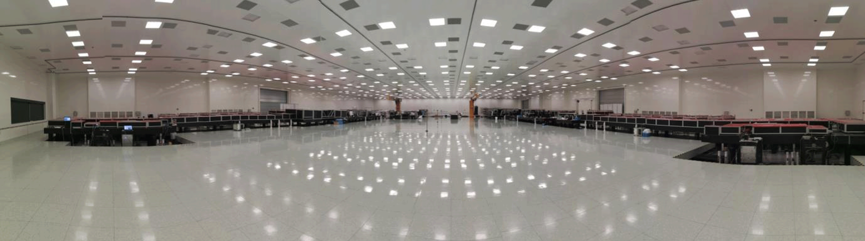
Figure 13. The two 10 PW lasers installed in the ELI-NP facility (picture courtesy of ELI-NP).
2.3 Geographic overview of facilities – Asia
Asia has a long history of operating ultra-high-power laser facilities and has been pioneers in their development and implementation. China, Japan and the South Korea have all had, or have, facilities with world-leading capabilities, described in the sections below. India has only recently commissioned its first petawatt class laser facility.
The Asian Intense Laser Network is an unfunded consortium which uses the ASILS (Asian Symposium on Intense Laser Science) conference series and summer schools to maintain interactions between the various groups throughout Asia. The following is a summary, by country/institute, of the ultra-high-power lasers in Asia.
2.3.1 China
China has seen the greatest growth internationally in the development of ultra-high-power lasers and in their applications. This research is clustered around three main cities: Shanghai, Beijing and Mianyang. In Shanghai there are the following research institutes: SIOM (Shanghai Institute of Optics and Fine Mechanics) National Laboratory on High Power Laser and Physics (NLHPLP); SIOM State Key Laboratory of High Field Laser Physics; there is a further site within ShanghaiTech University operated by SIOM; and the Key Laboratory for Laser Plasma (Ministry of Education) at Shanghai Jiao Tong University. In Beijing there are high-power lasers situated at the Beijing National Laboratory for Condensed Matter Physics, Institute of Physics (IOP), Chinese Academy of Sciences (CAS) and Peking University. Mianyang is the location of the Laser Fusion Research Centre operated by the China Academy of Engineering Physics (CAEP).
At SIOM’s National Laboratory on High Power Laser and Physics (NLHPLP) the first Nd:glass petawatt laser in China was built as an auxiliary beamline to the Shenguang (Divine Light) SG-II high-energy facility[Reference Xu, Wang, Li, Dai, Lin, Gu and Zhu119] and is still operational. SG-II was an eight-beam Nd:glass laser facility operating at a total of 6 kJ IR or 2 kJ at 3 $\unicode[STIX]{x1D714}$
. A ninth beam of 4.5 kJ was commissioned and made operational in 2005, and subsequently converted to the SG-II UP PW beamline. SG-II UP also included the building of a separate 24 kJ, 3
$\unicode[STIX]{x1D714}$
. A ninth beam of 4.5 kJ was commissioned and made operational in 2005, and subsequently converted to the SG-II UP PW beamline. SG-II UP also included the building of a separate 24 kJ, 3 $\unicode[STIX]{x1D714}$
, 3 ns eight-beam facility. A recent paper describes the full scope of the facility[Reference Zhu, Zhu, Li, Zhu, Ma, Lu, Fan, Liu, Zhou, Xu, Zhang, Xie, Yang, Wang, Ouyang, Wang, Li, Yang, Fan, Sun, Liu, Liu, Zhang, Tao, Sun, Zhu, Wang, Jiao, Ren, Liu, Jiao, Huang and Lin120].
$\unicode[STIX]{x1D714}$
, 3 ns eight-beam facility. A recent paper describes the full scope of the facility[Reference Zhu, Zhu, Li, Zhu, Ma, Lu, Fan, Liu, Zhou, Xu, Zhang, Xie, Yang, Wang, Ouyang, Wang, Li, Yang, Fan, Sun, Liu, Liu, Zhang, Tao, Sun, Zhu, Wang, Jiao, Ren, Liu, Jiao, Huang and Lin120].
An additional OPCPA beamline has been recently added to the SG-II facility: the SG-II 5 PW laser facility is designed to deliver $150~\text{J}/30~\text{fs}$
pulses and pumped by second harmonic of the 7th and 9th beams of the SG-II facility. Currently, this system is operating at 37 J in 21 fs (1.76 PW) and has successfully been employed for high-energy physics experiments with a focusing intensity exceeding
$150~\text{J}/30~\text{fs}$
pulses and pumped by second harmonic of the 7th and 9th beams of the SG-II facility. Currently, this system is operating at 37 J in 21 fs (1.76 PW) and has successfully been employed for high-energy physics experiments with a focusing intensity exceeding $10^{19}~\text{W}/\text{cm}^{2}$
. The third phase with a high-energy OPCPA stage as the master amplifier is now under construction, and compressed 5 PW pulses will be achieved in the near future[Reference Zhu, Xie, Sun, Kang, Yang, Guo, Zhu, Zhu, Gao, Liang, Cui, Yang, Zhang and Lin121].
$10^{19}~\text{W}/\text{cm}^{2}$
. The third phase with a high-energy OPCPA stage as the master amplifier is now under construction, and compressed 5 PW pulses will be achieved in the near future[Reference Zhu, Xie, Sun, Kang, Yang, Guo, Zhu, Zhu, Gao, Liang, Cui, Yang, Zhang and Lin121].
SIOM’s State Key Laboratory of High Field Laser Physics was the home of the first Ti:sapphire petawatt class laser in China which delivered 0.89 PW in 29 fs pulses at 800 nm in 2006[Reference Liang, Leng, Wang, Li, Lin, Zhao, Jiang, Lu, Hu, Zhang, Lu, Yin, Jiang, Lu, Wei, Zhu, Li and Xu122]. The ‘Qiangguang’ (Intense Light) Ti:sapphire laser facility was then upgraded and produced powers of 2 PW (52 J, 26 fs) in 2012, the highest peak powers ever achieved from a laser system at the time[Reference Chu, Liang, Yu, Xu, Xu, Ma, Lu, Liu, Leng, Li and Xu123]. A high-contrast front end gives contrasts to target of $1.5\times 10^{11}@100~\text{ps}$
. A further upgraded version of the main amplifier of the facility produces 192.3 J pulse energy and has demonstrated the production of 27 fs pulses at sub-aperture, indicating that 5 PW pulses would be produced if full-aperture beam compression could be achieved[Reference Chu, Gan, Liang, Yu, Lu, Wang, Wang, Xu, Lu, Yin, Leng, Li and Xu124]. The laser is located in a building where space limits the option of a large vacuum compressor, and this facility is therefore currently operational at the 1 PW level.
$1.5\times 10^{11}@100~\text{ps}$
. A further upgraded version of the main amplifier of the facility produces 192.3 J pulse energy and has demonstrated the production of 27 fs pulses at sub-aperture, indicating that 5 PW pulses would be produced if full-aperture beam compression could be achieved[Reference Chu, Gan, Liang, Yu, Lu, Wang, Wang, Xu, Lu, Yin, Leng, Li and Xu124]. The laser is located in a building where space limits the option of a large vacuum compressor, and this facility is therefore currently operational at the 1 PW level.
The first multi-TW OPCPA laser in the world was also developed within the laboratory producing $570~\text{mJ}/155~\text{fs}$
, giving 3.67 TW in 2002[Reference Yang, Xu, Leng, Lu, Lin, Zhang, Li, Zhang, Yin and Tang125]. In 2012 they started to implement a 10 PW CPA-OPCPA hybrid laser system with the OPCPA booster amplifier based on a 215 mm LBO crystal. The peak power of 0.61 PW was achieved with a pulse energy of 28.7 J in a 33.8 fs pulse at 800 nm in 2013[Reference Xu, Yu, Liang, Chu, Hu, Ma, Xu, Wang, Lu, Lu, Yue, Zhao, Fan, Tu, Leng, Li and Xu126], and then in 2015 they improved the output to 1 PW by using a 100 mm LBO crystal with a pulse energy of 45.3 J in a 32 fs pulse[Reference Yu, Liang, Xu, Li, Peng, Hu, Wang, Lu, Chu, Gan, Liu, Liu, Wang, Lu, Yin, Leng, Li and Xu127]. However, the final 10 PW (300 J in 30 fs) performance of the laser system is delayed due to the availability of large-aperture LBO crystals.
$570~\text{mJ}/155~\text{fs}$
, giving 3.67 TW in 2002[Reference Yang, Xu, Leng, Lu, Lin, Zhang, Li, Zhang, Yin and Tang125]. In 2012 they started to implement a 10 PW CPA-OPCPA hybrid laser system with the OPCPA booster amplifier based on a 215 mm LBO crystal. The peak power of 0.61 PW was achieved with a pulse energy of 28.7 J in a 33.8 fs pulse at 800 nm in 2013[Reference Xu, Yu, Liang, Chu, Hu, Ma, Xu, Wang, Lu, Lu, Yue, Zhao, Fan, Tu, Leng, Li and Xu126], and then in 2015 they improved the output to 1 PW by using a 100 mm LBO crystal with a pulse energy of 45.3 J in a 32 fs pulse[Reference Yu, Liang, Xu, Li, Peng, Hu, Wang, Lu, Chu, Gan, Liu, Liu, Wang, Lu, Yin, Leng, Li and Xu127]. However, the final 10 PW (300 J in 30 fs) performance of the laser system is delayed due to the availability of large-aperture LBO crystals.
In the joint laboratory of SIOM and ShanghaiTech University, the team from SIOM’s State Key Laboratory of High Field Laser Physics is constructing SULF (Shanghai Superintense Ultrafast Laser Facility), a new standalone Ti:sapphire laser facility in a purpose-built building (Figure 14). The facility will deliver 10 PW, 1 PW, and 100 TW beamlines delivered to three target areas constructed underground. The SULF Prototype was constructed in a neighbouring building but without the room for a target chamber. In 2016 the laser facility achieved powers of 5.4 PW[Reference Gan, Yu, Li, Wang, Liang, Liu, Li, Guo, Fan, Yuan, Xu, Liu, Xu, Lu, Lu, Yin, Leng, Li and Xu128], with an ultimate specification of 10 PW, which is currently limited by the availability of suitable gratings. They also successfully demonstrated the final Ti:sapphire amplifier for 10 PW[Reference Li, Gan, Yu, Wang, Liu, Guo, Xu, Xu, Hang, Xu, Wang, Huang, Cao, Yao, Zhang, Chen, Tang, Li, Liu, Li, He, Yin, Liang, Leng, Li and Xu129], delivering 339 J at 800 nm with a 235-mm-diameter Ti:sapphire final amplifier. The pump-to-signal conversion efficiency of the final amplifier was demonstrated to be 32.1%. With the compressor transmission efficiency of 64% and the compressed pulse duration of 21 fs obtained with sub-aperture compression, this laser system would deliver 10.3 PW. New, full-aperture gold-coated gratings from Jobin Yvon were installed when the laser was moved into the purpose-built SULF building. The facility became operational in 2019, with an upgraded pump laser providing 10 PW laser pulses to be delivered to target at one shot per minute[Reference Cartlidge130].
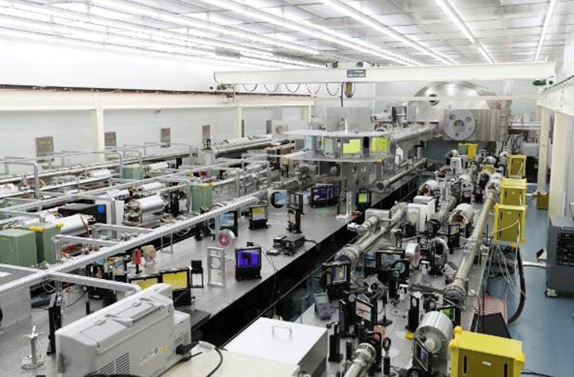
Figure 14. The SULF Prototype laser during final commissioning before being transferred to the SULF building (picture courtesy of SIOM).
At the Key Laboratory for Laser Plasmas (LLP), Shanghai Jiao Tong University a commercial PULSAR Ti:sapphire laser from Amplitude Technologies operates at 200 TW, delivering 5 J, 25 fs pulses at repetition rates between 5 and 10 Hz[Reference Wang, Ma, Wang, Yuan, Xie, Ge, Liu, Yuan, Zhu and Qian131, 132]. They also have a research programme into high-average-power OPCPA systems and plan to construct a 15 PW facility on a small campus they have in Pudong, Shanghai. The facility is single-shot in the first phase and will be eventually upgraded to a high repetition rate with kW average power. The LLP also has a mid-IR OPCPA system operating at $2.2~\unicode[STIX]{x03BC}\text{m}$
and 100 TW, which is included in this review as it has been identified as a possible way forward for future petawatt class laser facilities.
$2.2~\unicode[STIX]{x03BC}\text{m}$
and 100 TW, which is included in this review as it has been identified as a possible way forward for future petawatt class laser facilities.
At the Laser Fusion Research Centre, CAEP, Mianyang SILEX-I was an early Ti:sapphire petawatt class facility. The facility produced 9 J pulses at 30 fs, giving an output power of 286 TW at a repetition rate of 0.15 Hz[Reference Peng, Zhang, Zhang, Tang, Zheng, Zheng, Wei, Ding, Gou, Zhou and Pei133]. The facility was able to produce focused intensities of $10^{20}~\text{W}/\text{cm}^{2}$
without the need for deformable mirror corrections. This system has been incorporated into their Xingguang (Star Light) XG-III facility (a femtosecond, picosecond and nanosecond beam capability). The three beamlines produce 0.7 PW at 800 nm in 26.8 fs, 0.6 PW at 1053 nm in 0.5–10 ps, and a 527 nm nanosecond beam delivering 575 J[Reference Zhu, Zhou, Su, Xie, Huang, Zeng, Wang, Wang, Zuo, Jiang, Zhao, Li, Hu, Zheng, Dai, Chen, Dang, Liu, Xu, Lin, Zhang, Deng, Xie, Feng, Peng, Zhao, Wang, Zhou, Sun, Guo, Zhou, Wen, Wu, Li, Huang, Wang, Jiang, Gu, Jing and Zhang134].
$10^{20}~\text{W}/\text{cm}^{2}$
without the need for deformable mirror corrections. This system has been incorporated into their Xingguang (Star Light) XG-III facility (a femtosecond, picosecond and nanosecond beam capability). The three beamlines produce 0.7 PW at 800 nm in 26.8 fs, 0.6 PW at 1053 nm in 0.5–10 ps, and a 527 nm nanosecond beam delivering 575 J[Reference Zhu, Zhou, Su, Xie, Huang, Zeng, Wang, Wang, Zuo, Jiang, Zhao, Li, Hu, Zheng, Dai, Chen, Dang, Liu, Xu, Lin, Zhang, Deng, Xie, Feng, Peng, Zhao, Wang, Zhou, Sun, Guo, Zhou, Wen, Wu, Li, Huang, Wang, Jiang, Gu, Jing and Zhang134].
Shenguang-IV (SG-IV)[Reference Zhang and He135] is a proposed megajoule facility to be built at the Laser Fusion Research Centre as an ignition demonstrator. The facility is planned to be constructed following the successful commissioning of SG-III, designed to operate with 48 beams at 200 kJ. The initial specification of SG-IV is to be of similar scale to NIF and LMJ, although the design is yet to be finalized. Design options can be tested on SG-IIIP, a separate prototype beamline within the SG-III building.
There is also a 4.9 PW all-OPCPA laser at Mianyang (CAEP-PW) operating at 800 nm delivering 168.7 J after the final amplifier and 91.1 J post-compressor in 18.6 fs[Reference Zeng, Zhou, Zuo, Zhu, Su, Wang, Wang, Huang, Jiang, Jiang, Guo, Xie, Zhou, Wu, Mu, Peng and Jing136]. It is planned that by using larger-aperture LBO crystals, $200~\text{mm}\times 200~\text{mm}$
, 15 PW will be achieved.
$200~\text{mm}\times 200~\text{mm}$
, 15 PW will be achieved.
The National Laboratory for Condensed Matter, IOP Beijing operates the Xtreme Light III (XL-III) Ti:sapphire facility which generates 32 J in a 28 fs pulse delivering 1.16 PW to target at focused intensities ${>}10^{22}~\text{W}/\text{cm}^{2}$
[Reference Wang, Liu, Shen, Zhang, Teng and Wei137]. It was the first facility to produce more than 1 PW of laser power in China, and has high fidelity pulses with contrasts of
${>}10^{22}~\text{W}/\text{cm}^{2}$
[Reference Wang, Liu, Shen, Zhang, Teng and Wei137]. It was the first facility to produce more than 1 PW of laser power in China, and has high fidelity pulses with contrasts of $10^{10}@100~\text{ps}$
. This facility was moved to a new building and had its pump lasers upgraded. It is expected the peak power of the system will be 1.5 PW, with a pulse duration shorter than 20 fs and a contrast ratio better than
$10^{10}@100~\text{ps}$
. This facility was moved to a new building and had its pump lasers upgraded. It is expected the peak power of the system will be 1.5 PW, with a pulse duration shorter than 20 fs and a contrast ratio better than $10^{11}$
at a time of 10 ps.
$10^{11}$
at a time of 10 ps.
At the Institute of Heavy Ion Physics, Peking University CLAPA (Compact LAser-Plasma Accelerator) is a dedicated facility for laser-driven plasma accelerator experiments; it includes a 5 J, 25 fs, 5 Hz, 200 TW commercial Ti:sapphire laser supplied by Thales, a plasma accelerator, proton beam transport line and the application platform[Reference Yan, Lin, Lu, Zhu, Zou, Wang, Liu, Zhao, Zhu, Geng, Fu, Shang, Cao, Shou, Song, Lu, Yuan, Guo, He and Chen138]. The XPW technique is used in the system, allowing nanosecond contrasts of $10^{9}$
, and the picosecond contrast can reach
$10^{9}$
, and the picosecond contrast can reach $10^{10}$
20 ps in front of the pulse. There is also a proposal to install a 2 PW, 1 Hz Ti:sapphire laser for proton acceleration studies.
$10^{10}$
20 ps in front of the pulse. There is also a proposal to install a 2 PW, 1 Hz Ti:sapphire laser for proton acceleration studies.
2.3.2 Japan
The Institute of Laser Engineering (ILE), Osaka University is host to the GEKKO XII Nd:glass facility (Figure 15); the first large-scale (12-beam) laser system employing Nd-doped phosphate laser glasses for inertial confinement fusion research[Reference Yamanaka, Kato, Izawa, Yoshida, Yamanaka, Sasaki, Nakatsuka, Mochizuki, Kuroda and Nakai139]. Following the development of the first large-aperture 30 TW CPA Nd:glass laser at ILE[Reference Yamakawa, Barty, Shiraga and Kato23], the first petawatt class laser in Asia was constructed as part of the high-energy nanosecond capability of the GEKKO XII facility[Reference Kitagawa, Fujita, Kodama, Yoshida, Matsuo, Jitsuno, Kawasaki, Kitamura, Kanabe, Sakabe, Shigemori, Miyanaga and Izawa140]. This petawatt beamline was composed of an OPCPA front end, Nd:glass large-aperture amplifiers and a double-pass compressor to produce 420 J in 470 fs, giving an output power of 0.9 PW. An $f/7$
off-axis parabola was used to focus the beam to target, giving focused intensities of
$f/7$
off-axis parabola was used to focus the beam to target, giving focused intensities of $2.5\times 10^{19}~\text{W}/\text{cm}^{2}$
.
$2.5\times 10^{19}~\text{W}/\text{cm}^{2}$
.
Within the GEKKO XII facility, the LFEX (Laser for Fast Ignition Experiment) facility has been commissioned as a fast ignitor[Reference Tabak, Hammer, Glinsky, Kruer, Wilks, Woodworth, Campbell and Perry141] demonstrator for the FIREX project[Reference Mima, Azechi, Johzaki, Kitagawa, Kodama, Kozaki, Miyanaga, Nagai, Nagatomo, Nakai, Nishimura, Norimatsu, Shiraga, Tanaka and Izawa142, Reference Shiraga, Fujioka, Nakai, Watari, Nakamura, Arikawa, Hosoda, Nagai, Koga, Kikuchi, Ishii, Sogo, Shigemori, Nishimura, Zhang, Tanabe, Ohira, Fujii, Namimoto, Sakawa, Maegawa, Ozaki, Tanaka, Habara, Iwawaki, Shimada, Nagatomo, Johzaki, Sunahara, Murakami, Sakagami, Taguchi, Norimatsu, Homma, Fujimoto, Iwamoto, Miyanaga, Kawanaka, Jitsuno, Nakata, Tsubakimoto, Sueda, Morio, Matsuo, Kawasaki, Sawai, Tsuji, Murakami, Kanabe, Kondo, Kodama, Sarukura, Shimizu, Mima and Azechi143]. The LFEX laser is composed of $2\times 2$
segmented beams. Each beam is
$2\times 2$
segmented beams. Each beam is $32~\text{cm}\times 32~\text{cm}$
in size and is compressed with two pairs of dielectric gratings and focused to target with a 4 m focal length off-axis parabola, giving a focal spot of
$32~\text{cm}\times 32~\text{cm}$
in size and is compressed with two pairs of dielectric gratings and focused to target with a 4 m focal length off-axis parabola, giving a focal spot of $30{-}60~\unicode[STIX]{x03BC}\text{m}$
in diameter with 2.5 kJ energy/beam. The pulse rise time is 1 ps and the pulse duration is controllable through 1–20 ps, providing petawatt peak powers[Reference Azechi, Mima, Fujimoto, Fujioka, Homma, Isobe, Iwamoto, Jitsuno, Johzaki, Kodama, Koga, Kondo, Kawanaka, Mito, Miyanaga, Motojima, Murakami, Nagatomo, Nagai, Nakai, Nakamura, Nakamura, Nakazato, Nakao, Nishihara, Nishimura, Norimatsu, Ozaki, Sakagami, Sakawa, Sarukura, Shigemori, Shimizu, Shiraga, Sunahara, Taguchi, Tanaka and Tsubakimoto144, Reference Azechi145]. The output power of the compressed beam is currently 2 PW in 1 ps. A full-aperture deformable mirror has been installed in one of the four beams before the pulse compressor to reduce the wavefront distortion. Pulse contrast ratio (pedestal to main peak) has been improved from
$30{-}60~\unicode[STIX]{x03BC}\text{m}$
in diameter with 2.5 kJ energy/beam. The pulse rise time is 1 ps and the pulse duration is controllable through 1–20 ps, providing petawatt peak powers[Reference Azechi, Mima, Fujimoto, Fujioka, Homma, Isobe, Iwamoto, Jitsuno, Johzaki, Kodama, Koga, Kondo, Kawanaka, Mito, Miyanaga, Motojima, Murakami, Nagatomo, Nagai, Nakai, Nakamura, Nakamura, Nakazato, Nakao, Nishihara, Nishimura, Norimatsu, Ozaki, Sakagami, Sakawa, Sarukura, Shigemori, Shimizu, Shiraga, Sunahara, Taguchi, Tanaka and Tsubakimoto144, Reference Azechi145]. The output power of the compressed beam is currently 2 PW in 1 ps. A full-aperture deformable mirror has been installed in one of the four beams before the pulse compressor to reduce the wavefront distortion. Pulse contrast ratio (pedestal to main peak) has been improved from $10^{10}$
to better than
$10^{10}$
to better than $10^{11}$
by using a plasma mirror in front of the target.
$10^{11}$
by using a plasma mirror in front of the target.
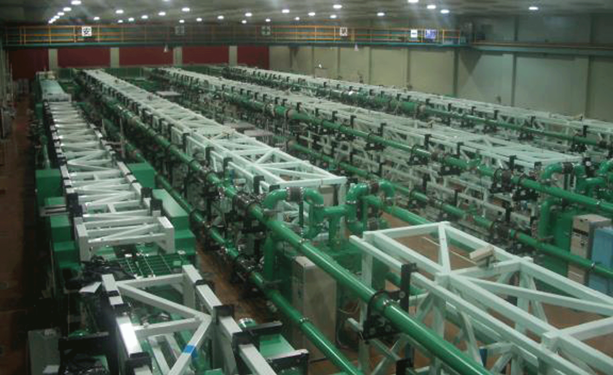
Figure 15. The GEKKO XII (right) and LFEX (left) lasers at ILE, Osaka University, Japan (picture courtesy of Osaka University).
At the Kansai Photon Science Institute (KPSI), QST (National Institutes for Quantum and Radiological Science and Technology), Kyoto, Japan (previously Advanced Photon Research Centre (APRC), JAEA (Japan Atomic Energy Agency)), the J-KAREN (JAEA-Kansai Advanced Relativistic ENgineering) Ti:sapphire laser system was the world’s first petawatt class Ti:sapphire facility, generating 0.85 PW in 2003 (28.4 J at 33 fs)[Reference Aoyama, Yamakawa, Akahane, Ma, Inoue, Ueda and Kiriyama39]. This facility could operate at 50 TW at 10 Hz and at petawatt levels once every 30 min, due to thermal considerations in the final booster amplifier. The upgraded J-KAREN-P (J-KAREN-Petawatt), the first hybrid OPCPA/Ti:sapphire system, has a specification of 1 PW (30 J, 30 fs) and 0.1 Hz repetition rate with $f/1.3$
off-axis parabola focusing. This system is currently operated at 0.3 PW, delivering an intensity of
$f/1.3$
off-axis parabola focusing. This system is currently operated at 0.3 PW, delivering an intensity of $10^{22}~\text{W}/\text{cm}^{2}$
on target with a high temporal contrast of
$10^{22}~\text{W}/\text{cm}^{2}$
on target with a high temporal contrast of $10^{12}$
[Reference Kiriyama, Pirozhkov, Nishiuchi, Fukuda, Ogura, Sagisaka, Miyasaka, Mori, Sakaki, Dover, Kondo, Koga, Esirkepov, Kando and Kondo146].
$10^{12}$
[Reference Kiriyama, Pirozhkov, Nishiuchi, Fukuda, Ogura, Sagisaka, Miyasaka, Mori, Sakaki, Dover, Kondo, Koga, Esirkepov, Kando and Kondo146].
For laser wakefield electron acceleration, LAPLACIAN (Laser Acceleration PLAtform as a Coordinated Innovative ANchor) is being built at RIKEN SPring-8 Centre, Harima, Japan in the framework of a Japanese national project ImPACT (Impulsing PAradigm Change through disruptive Technologies program). This facility is equipped with a Ti:sapphire laser system specially designed to attain stable electron staging acceleration by LWFA. The concept of the laser system was designed by Osaka University and installed by Amplitude Systems. A laser beam from an oscillator is divided into three beams, which are amplified and compressed to provide three beams of 1 J/20 fs at 10 Hz, 2 J/50 fs at 5 Hz and 10 J/100 fs at 0.1 Hz. These beams are then provided to an injector, a phase rotator, and a booster, respectively, with minimum timing jitter. The laser parameters for each stage can be controlled independently to maximize the total performance of the electron acceleration.
At SACLA, the X-ray free electron laser (XFEL) facility, operated by RIKEN SPring-8 Centre, Harima, Japan, there is a Ti:sapphire laser system delivered by Thales Optronique with two 0.5 PW laser beams. This has been commissioned with a maximum energy of 12.5 J in 25 fs at a 1 Hz repetition rate. The laser has been planned as one of the HERMES laser systems, which is coupled to SACLA under a RIKEN-Osaka University collaboration. In 2018 one beam has started operation in combination with SACLA for user experiments at 200 TW (8 J, 40 fs) with a reduced rate of once every few minutes.
The high-power laser community in Japan, led by ILE Osaka, together with KPSI QST, has proposed a concept design of a high-repetition-rate and high-power laser facility J-EPOCH (Japan-Establishment for POwer laser Community Harvest). This facility is a $16~\text{kJ}/16~\text{Hz}/1~\text{ns}/160$
beam laser system, which is composed of 16 units of ten beams, with each beam providing an energy of 100 J at 100 Hz and a peak power of 1 PW at 50–100 Hz. J-EPOCH will provide laser-accelerated radiation and particle beams (GeV electrons, protons, X-rays,
$16~\text{kJ}/16~\text{Hz}/1~\text{ns}/160$
beam laser system, which is composed of 16 units of ten beams, with each beam providing an energy of 100 J at 100 Hz and a peak power of 1 PW at 50–100 Hz. J-EPOCH will provide laser-accelerated radiation and particle beams (GeV electrons, protons, X-rays, $\unicode[STIX]{x03B3}$
-rays and neutrons) and 25 PW beam lines. The 25 PW beam line consists of two
$\unicode[STIX]{x03B3}$
-rays and neutrons) and 25 PW beam lines. The 25 PW beam line consists of two $10~\text{PW}/20~\text{fs}$
beams with a 10 Hz repetition rate based on Ti:sapphire lasers and one
$10~\text{PW}/20~\text{fs}$
beams with a 10 Hz repetition rate based on Ti:sapphire lasers and one $5~\text{PW}/\text{a}$
few
$5~\text{PW}/\text{a}$
few $\text{ps}/5{-}10~\text{kJ}$
beam with a 10 Hz repetition rate based on ceramic lasers.
$\text{ps}/5{-}10~\text{kJ}$
beam with a 10 Hz repetition rate based on ceramic lasers.
2.3.3 South Korea
At the Centre for Relativistic Laser Science (CoReLS), Gwangju, South Korea, a petawatt Ti:sapphire laser facility (Figure 16) has been operational for the exploration of superintense laser–matter interactions by inheriting the petawatt laser facility developed by Advanced Photonics Research Institute (APRI), Gwangju Institute of Science and Technology (GIST). The petawatt laser facility first achieved petawatt capability in 2010 with a 33 J beam in 30 fs, delivering 1.1 PW at a repetition rate of 0.1 Hz[Reference Sung, Lee, Yu, Jeong and Lee147], and added the second petawatt beamline of 30 fs, 1.5 PW[Reference Yu, Lee, Sung, Yoon, Jeong and Lee148], which is claimed to be the very first 0.1 Hz Ti:sapphire petawatt laser in the world. After the establishment of the CoReLS, a research centre of the Institute for Basic Science (IBS), in 2012 the 1.5 PW laser beamline was upgraded to a 4 PW laser in 2016, delivering 83 J in 19.4 fs (4.2 PW) at 0.1 Hz with a shot-to-shot energy stability of 1.5%[Reference Sung, Lee, Yoo, Yoon, Lee, Yang, Son, Jang, Lee and Nam149]. The upgraded laser with XPW and OPA front end stages can achieve focused intensities of $10^{23}~\text{W}/\text{cm}^{2}$
, with contrast measured to be
$10^{23}~\text{W}/\text{cm}^{2}$
, with contrast measured to be $10^{12}$
up to 150 ps before the main pulse. The measured laser intensity, with an
$10^{12}$
up to 150 ps before the main pulse. The measured laser intensity, with an $f/1.6$
off-axis parabola, was
$f/1.6$
off-axis parabola, was $5.5\times 10^{22}~\text{W}/\text{cm}^{2}$
with a 3 PW laser pulse[Reference Yoon, Jeon, Shin, Lee, Lee, Choi, Kim, Sung and Nam150].
$5.5\times 10^{22}~\text{W}/\text{cm}^{2}$
with a 3 PW laser pulse[Reference Yoon, Jeon, Shin, Lee, Lee, Choi, Kim, Sung and Nam150].
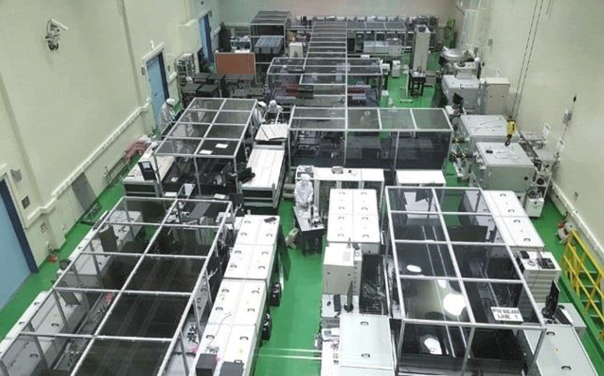
Figure 16. The multi-petawatt laser facility at CoReLS, South Korea (picture courtesy of CoReLS).
At ETRI (Electronics and Telecommunications Research Institute) Daejeon, South Korea a 200 TW (5 J in 20 fs) 5–10 Hz PULSAR Ti:sapphire laser system from Amplitude Technologies has been upgraded to 1 PW. The facility is called EXLS (ETRI eXtreme Light Source) and operates at 800 nm, giving 31 J in 22 fs at 0.1 Hz. The 200-mm-diameter beam has $f/1.8$
focusing.
$f/1.8$
focusing.
2.3.4 India
The RRCAT (Raja Ramana Centre for Advanced Technology), Indore, Dept of Atomic Energy is the premier Indian institute working in the field of lasers and particle accelerators. In 2012 a 150 TW Ti:sapphire laser operating at 5 Hz was procured from Amplitude Technologies, France. The system provides 3.75 J in 25 fs with a pre-pulse contrast of ${\sim}10^{10}$
at 300 ps. This system is mostly used to investigate electron acceleration in gas jets and ion acceleration in thin foil targets. Now RRCAT is in the process of establishing a 1 PW Ti:sapphire laser facility. The laser uses an XPW front end. The final Ti:sapphire laser amplifier is pumped by four Nd:glass pump lasers (ATLAS, Thales, France) providing 100 J at 2
${\sim}10^{10}$
at 300 ps. This system is mostly used to investigate electron acceleration in gas jets and ion acceleration in thin foil targets. Now RRCAT is in the process of establishing a 1 PW Ti:sapphire laser facility. The laser uses an XPW front end. The final Ti:sapphire laser amplifier is pumped by four Nd:glass pump lasers (ATLAS, Thales, France) providing 100 J at 2 $\unicode[STIX]{x1D714}$
. The final power is 1.1 PW at 25 J, 25 fs operating at 0.1 Hz.
$\unicode[STIX]{x1D714}$
. The final power is 1.1 PW at 25 J, 25 fs operating at 0.1 Hz.
3 Discussion of fifty years of ultra-high-power lasers
Since the first demonstration of the laser in 1960 by Theodore Maiman[Reference Maiman9], the principal defining characteristic of lasers has been their ability to focus unprecedented powers of light in space, time and frequency. Shortly after its discovery, the United States Department of Energy’s national laboratories aggressively initiated research and development on high-energy, high-peak-power lasers for laser fusion. Similar efforts took place in laboratories in Europe and later in Asia, and saw record peak powers rapidly scaling to the 100 TW level. Twenty years ago, LLNL’s petawatt laser based on kilojoule CPA applied to one beamline of the Nova fusion laser[Reference Perry, Pennington, Stuart, Tietbohl, Britten, Brown, Herman, Golick, Kartz, Miller, Powell, Vergino and Yanovsky2] represented a further decadal leap in peak power. ‘The PW,’ as it was called, opened our eyes to the science frontiers that high-intensity petawatt lasers offered $(10^{21}~\text{W}/\text{cm}^{2})$
.
$(10^{21}~\text{W}/\text{cm}^{2})$
.
Beyond achieving its anticipated goals of reaching the threshold to the ultra-relativistic regime, wherein a free electron oscillating in the laser field is accelerated to near the speed of light (peak intensity ${>}10^{18}~\text{W}/\text{cm}^{2}$
), unexpected discoveries such as the production of ions at multi-MeV energies, which have since become standard probes for high-energy-density science, further enhanced their impact. High-energy, short-pulse laser systems operating at petawatt peak powers (e.g., from
${>}10^{18}~\text{W}/\text{cm}^{2}$
), unexpected discoveries such as the production of ions at multi-MeV energies, which have since become standard probes for high-energy-density science, further enhanced their impact. High-energy, short-pulse laser systems operating at petawatt peak powers (e.g., from $20~\text{J}/20~\text{fs}$
to kJ/ps) have in the intervening two decades enabled a wide range of new high-energy (keV–GeV) particle and radiation sources for single-shot discovery science.
$20~\text{J}/20~\text{fs}$
to kJ/ps) have in the intervening two decades enabled a wide range of new high-energy (keV–GeV) particle and radiation sources for single-shot discovery science.
An important contribution to enhance the global capabilities is the recycling of components from national laboratories to academic environments, where their implementation is enhanced by university innovators. In the USA, following the closure of the Nova laser, several internationally recognized lasers were born including: PHELIX at GSI Darmstadt, Germany[Reference Bagnoud, Aurand, Blazevic, Borneis, Bruske, Ecker, Eisenbarth, Fils, Frank, Gaul, Goette, Haefner, Hahn, Harres, Heuck, Hochhaus, Hoffmann, Javorková, Kluge, Kuehl, Kunzer, Kreutz, Merz-Mantwill, Neumayer, Onkels, Reemts, Rosmej, Roth, Stoehlker, Tauschwitz, Zielbauer, Zimmer and Witte101]; Vulcan PW at the Central Laser Facility[Reference Danson, Brummitt, Clarke, Collier, Fell, Frackiewicz, Hancock, Hawkes, Hernandez-Gomez, Holligan, Hutchinson, Kidd, Lester, Musgrave, Neely, Neville, Norreys, Pepler, Reason, Shaikh, Winstone, Wyatt and Wyborn36], UK; LEOPARD at the University of Nevada, Reno, USA[Reference Wiewior, Astanovitskiy, Aubry, Batie, Caron, Chalyy, Cowan, Haefner, Le Galloudec, Le Galloudec, Macaulay, Nalajala, Pettee, Samek, Stepanenko and Vesco151]; and Texas PW at the University of Texas at Austin, USA[Reference Gaul, Martinez, Blakeney, Jochmann, Ringuette, Hammond, Borger, Escamilla, Douglas, Henderson, Dyer, Erlandson, Cross, Caird, Ebbers and Ditmire77]. In France, following the closure of the Phebus facility at Limeil-Valenton, the LULI-2000 facility was created[Reference Zou, Blanc, Audebert, Janicot, Sautivet, Martin, Sauteret, Paillard, Jacquemot and Amiranoff152] at Ecole Polytechnique, with many components also contributing to the Vulcan PW in the UK and PHELIX in Germany.
The physics at the laser–target interaction point is strongly governed by the intensity of the laser, although the reporting of peak power has become the standard in defining laser capability. This might be because a direct measurement of the focal intensity is extremely difficult. Researchers have measured the ionization ratio of atoms in the light field (optical field ionization) to assess the focused peak intensities[Reference Akahane, Ma, Fukuda, Aoyoma, Kiriyama, Sheldakova, Kudryashov and Yamakawa153]. Furthermore, many new high-peak-power laser systems have arisen, and technology has improved over the original petawatt, but the peak focal intensities achieved have only increased from ${\sim}10^{21}$
to
${\sim}10^{21}$
to ${\sim}10^{22}~\text{W}/\text{cm}^{2}$
. However, the usable intensities for experiments have typically been an order of magnitude less than this, partly due to a lack of emphasis on the integrated capabilities required for practical exploitation, as opposed to academic demonstration. Notably, peak intensity demonstrations have occurred on specific Nd:glass-based lasers: the Vulcan PW in the UK at
${\sim}10^{22}~\text{W}/\text{cm}^{2}$
. However, the usable intensities for experiments have typically been an order of magnitude less than this, partly due to a lack of emphasis on the integrated capabilities required for practical exploitation, as opposed to academic demonstration. Notably, peak intensity demonstrations have occurred on specific Nd:glass-based lasers: the Vulcan PW in the UK at $1\times 10^{21}~\text{W}/\text{cm}^{2}$
(2004)[Reference Danson, Collier, Neely, Barzanti, Damerell, Edwards, Hutchinson, Key, Norreys, Pepler, Ross, Taday, Toner, Trentelman, Walsh, Winstone and Wyatt35]; the Ti:sapphire-based HERCULES laser at the University of Michigan, USA at
$1\times 10^{21}~\text{W}/\text{cm}^{2}$
(2004)[Reference Danson, Collier, Neely, Barzanti, Damerell, Edwards, Hutchinson, Key, Norreys, Pepler, Ross, Taday, Toner, Trentelman, Walsh, Winstone and Wyatt35]; the Ti:sapphire-based HERCULES laser at the University of Michigan, USA at $1\times 10^{22}~\text{W}/\text{cm}^{2}$
(2004)[Reference Bahk, Rousseau, Planchon, Chvykov, Kalintchenko, Maksimchuk, Mourou and Yanovsky70], J-KAREN-P in Japan at
$1\times 10^{22}~\text{W}/\text{cm}^{2}$
(2004)[Reference Bahk, Rousseau, Planchon, Chvykov, Kalintchenko, Maksimchuk, Mourou and Yanovsky70], J-KAREN-P in Japan at $1\times 10^{22}~\text{W}/\text{cm}^{2}$
(2018)[Reference Kiriyama, Pirozhkov, Nishiuchi, Fukuda, Ogura, Sagisaka, Miyasaka, Mori, Sakaki, Dover, Kondo, Koga, Esirkepov, Kando and Kondo146], and most recently, the record intensity of
$1\times 10^{22}~\text{W}/\text{cm}^{2}$
(2018)[Reference Kiriyama, Pirozhkov, Nishiuchi, Fukuda, Ogura, Sagisaka, Miyasaka, Mori, Sakaki, Dover, Kondo, Koga, Esirkepov, Kando and Kondo146], and most recently, the record intensity of $5.5\times 10^{22}~\text{W}/\text{cm}^{2}$
was demonstrated at the CoReLS laser[Reference Yoon, Jeon, Shin, Lee, Lee, Choi, Kim, Sung and Nam150].
$5.5\times 10^{22}~\text{W}/\text{cm}^{2}$
was demonstrated at the CoReLS laser[Reference Yoon, Jeon, Shin, Lee, Lee, Choi, Kim, Sung and Nam150].
It is interesting to note that even the highest-peak-power laser systems (10 PW and beyond) proposed or already in commissioning make no exception to this trend and largely predict intensities of only up to $10^{23}~\text{W}/\text{cm}^{2}$
(notably L4-ELI[45], EP-OPAL[Reference Zuegel154], SULF[Reference Li, Gan, Yu, Wang, Liu, Guo, Xu, Xu, Hang, Xu, Wang, Huang, Cao, Yao, Zhang, Chen, Tang, Li, Liu, Li, He, Yin, Liang, Leng, Li and Xu129] and SEL[Reference Cartlidge130]). A fundamental physics or engineering limit is not clear; however, material challenges such as imperfect diffraction gratings[Reference Bromage, Dorner and Jungquist155, Reference Hooker, Tang, Chekhlov, Collier, Divall, Ertel, Hawkes, Parry and Rajeev156], optics and gain materials reduce the overall laser focusability in time and space.
$10^{23}~\text{W}/\text{cm}^{2}$
(notably L4-ELI[45], EP-OPAL[Reference Zuegel154], SULF[Reference Li, Gan, Yu, Wang, Liu, Guo, Xu, Xu, Hang, Xu, Wang, Huang, Cao, Yao, Zhang, Chen, Tang, Li, Liu, Li, He, Yin, Liang, Leng, Li and Xu129] and SEL[Reference Cartlidge130]). A fundamental physics or engineering limit is not clear; however, material challenges such as imperfect diffraction gratings[Reference Bromage, Dorner and Jungquist155, Reference Hooker, Tang, Chekhlov, Collier, Divall, Ertel, Hawkes, Parry and Rajeev156], optics and gain materials reduce the overall laser focusability in time and space.

Figure 17. Geographic distribution of high-peak-power lasers (top). Diameter of circle is logarithmically proportional to peak laser power and circle colour is chosen for graphical clarity. Evolution of high-peak-power lasers ( ${>}$
100 GW) in the world over the last fifty years (bottom). Systems that are currently operating are shown as circles with solid borders; systems that were operating in the past but are now de-activated are shown as octagons with solid borders; and systems actively funded and being built are shown as circles with dashed borders. The diameter of the symbol is logarithmically proportional to laser pulse energy and the colour indicates the laser media used in the final amplifiers: Ti:sapphire (red), Nd:glass (grey), Yb:X (orange), Cr:X (yellow), optical parametric amplification (purple-blue), or gas (pink). As of early 2019, no high-power system has exceeded the 10 PW limit, even though there are several funded projects underway in Europe and Asia to break this barrier.
${>}$
100 GW) in the world over the last fifty years (bottom). Systems that are currently operating are shown as circles with solid borders; systems that were operating in the past but are now de-activated are shown as octagons with solid borders; and systems actively funded and being built are shown as circles with dashed borders. The diameter of the symbol is logarithmically proportional to laser pulse energy and the colour indicates the laser media used in the final amplifiers: Ti:sapphire (red), Nd:glass (grey), Yb:X (orange), Cr:X (yellow), optical parametric amplification (purple-blue), or gas (pink). As of early 2019, no high-power system has exceeded the 10 PW limit, even though there are several funded projects underway in Europe and Asia to break this barrier.
Despite this observation, the race to even higher peak power is underway (see Section 4.1 in this review). Figure 17 shows the development of peak power versus year across the world and by region. It can be seen that all early high-power lasers were derivatives of the US inertial confinement fusion (ICF) program and based on Nd:glass for gain media. With the invention of titanium-doped sapphire (Ti:sapphire) in 1982 at MIT Lincoln Lab[Reference Moulton26], which provides ${\sim}20\times$
more gain bandwidth at a
${\sim}20\times$
more gain bandwidth at a ${\sim}5\times$
lower saturation fluence compared to Nd:glass, the invention of ultra-short pulsed (
${\sim}5\times$
lower saturation fluence compared to Nd:glass, the invention of ultra-short pulsed ( ${<}$
100 fs) terawatt and petawatt laser systems became possible. Commercially available 100 TW–10 PW lasers rely on large-aperture Ti:sapphire, with the exception of a product by National Energetics that relies on a mix of Nd:phosphate and Nd:silicate glass to enhance the gain bandwidth in the amplifier chain. Figure 17 also shows that in the US currently no high-power lasers exceeding 1 PW are planned, despite its leadership in the past.
${<}$
100 fs) terawatt and petawatt laser systems became possible. Commercially available 100 TW–10 PW lasers rely on large-aperture Ti:sapphire, with the exception of a product by National Energetics that relies on a mix of Nd:phosphate and Nd:silicate glass to enhance the gain bandwidth in the amplifier chain. Figure 17 also shows that in the US currently no high-power lasers exceeding 1 PW are planned, despite its leadership in the past.
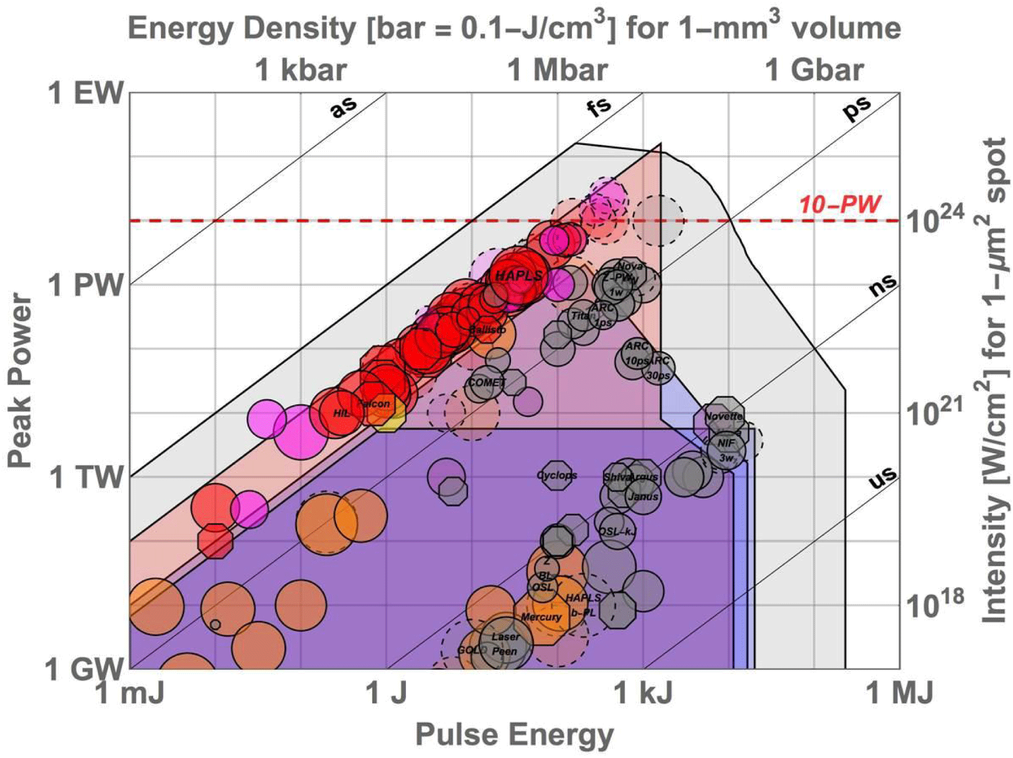
Figure 18. The current high-energy/high-power lasers globally (those that are operational represented by circles with continuous borders; those under construction represented by circles with dashed borders; or those that are decommissioned represented by octagons; with colour indicating the laser media of the final amplifier stage – defined in the legend in Figure 17).
A representation of the operational limits of high-power/high-energy laser systems is demonstrated in Figure 18. The figure includes those facilities that are operational, under construction, or decommissioned globally, with colour indicating the laser media of the final amplifier stage. The diameter of the circles/octagons are logarithmically proportional to the average power of the lasers shown. Vertical and horizontal axes are peak power and integrated pulse energy of a single (coherent) aperture – in the case of multi-beam lasers like the 192-beam NIF laser shown, total system performance is diagonally up and to the right by the number of beams. Diagonal lines indicate the laser pulse width corresponding to the pulse energy divided by peak power. The right vertical axis indicates the peak focal intensity that would be reached if the beam was focused to a spot of a square micron in area, while the upper horizontal axis indicates the energy density corresponding to depositing the laser pulse energy into a cubic millimetre volume. Four operational envelopes are shown, within which laser designs satisfy limits of:
∙ bandwidth constraints (left diagonal lines);
∙ aperture size limits (
$40~\text{cm}\times 40~\text{cm}$
perpendicular beam size for mirrors, lenses and nonlinear elements such as doublers; and
$40~\text{cm}\times 100~\text{cm}$
optic-normal for diffraction gratings);∙ nonlinear B-integral limits; and
∙ damage fluence limits.


Limits on aperture size and damage fluence limits determine the rightmost edges of the operational zones shown, while the B-integral (intensity) limit and max aperture size limit the peak power laser pulses in NIF-size apertures to <10 TW in the 1 J–10 kJ range, as shown. The damage threshold limits and bandwidth constraints of both gold and multi-layer dielectric metre-scale diffraction gratings are also indicated, as is the similar limits for fused silica. The damage threshold data presented by Stuart et al. [Reference Stuart, Feit, Herman, Rubenchik, Shore and Perry157] were used for the gold grating and fused silica limits as shown.
Figure 18 dramatically illustrates that high-peak-power laser development since the invention of CPA has been fundamentally constrained, especially in the case of Nd-glass lasers based on fusion energy laser technology, by energy limits determined by optic size and damage thresholds, and in the case of Ti:sapphire-based ultrashort-pulse lasers by bandwidth limits. The steady ascent of Ti:sapphire, OPCPA and Nd:glass technologies upward in peak power has, with the construction of several ten to multi-tens of petawatt systems, nearly reached the ${\sim}$
100 PW limit of metre-scale gold diffraction gratings. The continued progress of ultra-intense CPA lasers must therefore take a multi-beam approach. Non-CPA Nd:glass fusion lasers have taken this approach for decades, which is most dramatically demonstrated with the 192-beam NIF laser. This could take the form of either incoherent or coherent beam combination of
${\sim}$
100 PW limit of metre-scale gold diffraction gratings. The continued progress of ultra-intense CPA lasers must therefore take a multi-beam approach. Non-CPA Nd:glass fusion lasers have taken this approach for decades, which is most dramatically demonstrated with the 192-beam NIF laser. This could take the form of either incoherent or coherent beam combination of ${\sim}$
10 PW scale beams. Indeed, the Shanghai SEL facility is already taking that approach to reach the 100 PW scale by combining four multi-tens of petawatt beams. Finally, the pioneering work of the astronomy community should be noted here, who faced very similar challenges of optic size and performance degradation (atmospheric turbulence), which were overcome decades ago with multiple apertures and active beam combination.
${\sim}$
10 PW scale beams. Indeed, the Shanghai SEL facility is already taking that approach to reach the 100 PW scale by combining four multi-tens of petawatt beams. Finally, the pioneering work of the astronomy community should be noted here, who faced very similar challenges of optic size and performance degradation (atmospheric turbulence), which were overcome decades ago with multiple apertures and active beam combination.
The cumulative peak power of high-power laser systems worldwide is shown in Figure 19. In green colour are those that are operational, and in orange colour are those under construction (funded projects). Not shown are conceptual or proposed systems. Europe (including systems in Russia as they are geographically in continental Europe) and North America currently operate approximately the same amount of petawatts as Asia does. However, it can be clearly seen that both Europe and Asia are heavily investing in the installation of several laser systems with very high peak powers, while there is only one high-peak-power laser facility[Reference Barty, Key, Britten, Beach, Beer, Brown, Bryan, Caird, Carlson, Crane, Dawson, Erlandson, Fittinghoff, Hermann, Hoaglan, Iyer, Jones, Jovanovic, Komashko, Landen, Liao, Molander, Mitchell, Moses, Nielsen, Nguyen, Nissen, Payne, Pennington, Risinger, Rushford, Skulina, Spaeth, Stuart, Tietbohl and Wattellier55] currently being commissioned in North America.
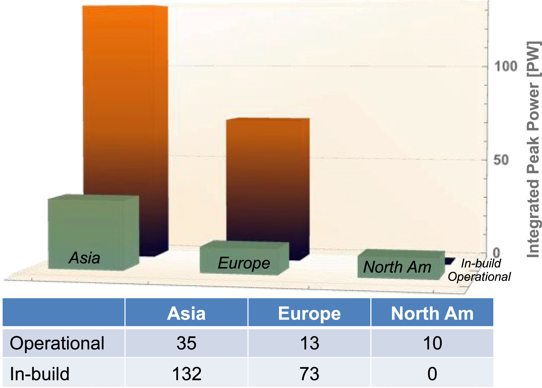
Figure 19. Cumulative peak power of operational (green columns) and in construction (orange columns) high-peak power ( ${>}$
0.1 PW) laser systems worldwide by area.
${>}$
0.1 PW) laser systems worldwide by area.
The increasing number of petawatt class lasers has also resulted in a significant increase in publications on science with petawatt lasers, as described in the recently published NAS Report for Opportunities in Brightest Light[5], with topics mainly in the areas of secondary source generation, plasma physics and basic science. Practical applications of such petawatt-class-driven capability include the development of proton and ion sources for medical applications, including cancer diagnostics and therapy; high-flux neutron sources for neutron radiography, special nuclear materials detection and materials science; high-brightness X-ray/gamma-ray sources for non-destructive interrogation and evaluation, medical diagnostics, ultrafast imaging at the molecular and atomic level, and nuclear photonics; and electron particle accelerators for next-generation colliders. The prospect of these applications has been demonstrated in proof-of-principle experiments using low-repetition-rate lasers (e.g., high-resolution micro computed tomography[Reference Roth, Jung, Falk, Guler, Deppert, Devlin, Favalli, Fernandez, Gautier, Geissel, Haight, Hamilton, Hegelich, Johnson, Merrill, Schaumann, Schoenberg, Schollmeier, Shimada, Taddeucci, Tybo, Wagner, Wender, Wilde and Wurden49]). The ultimate realization of these applications will require petawatt class lasers with photon flux 10 MJ/day < flux < 100 GJ/day, i.e., high repetition rates and higher average powers – beyond the ‘kW barrier’ to 10s of kW, and ultimately 100s of kW (Figure 20 quadrant ‘high-power applications’).
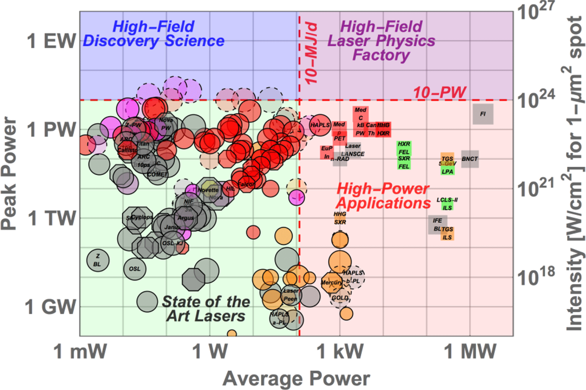
Figure 20. Peak power versus average power of high-peak-power, single-aperture laser systems and its primary pump lasers.
The peak power versus average power of high-peak-power, single-aperture laser systems and its primary pump lasers are shown in Figure 20. Key applications are indicated: a laser-plasma collider 300 kW unit cell (of which there would be ∼200 in a TeV-scale collider); positron emission tomography (PET) radioisotope production, hadron and boron-neutron capture (BNCT) therapies; ion and neutron beams for radiography, non-destructive inspection and materials processing; high-harmonic generation (HHG) light sources; laser-ablation-based space debris clearing; and inertial fusion energy unit cells (of which an IFE plant would require 100–200). Of particular note in this figure is the cluster of systems following a 45-degree upward path. These systems, predominately fusion laser architectures, scale both peak and average powers by scaling aperture and hence pulse energy at constant fluence. The four decades of sustained programmatic investments in fusion laser technology have brought innovations such as multi-beam operation, robust and aggressive thermal management, and novel materials to maintain scaling along this pathway. Future scaling along this well-travelled pathway will lead into the quadrant for applications at extreme peak powers.
An examination of the average powers of the operating and planned petawatt facilities across the world, shown in Figure 20, shows that average powers span from ${\sim}$
100 mW (notionally a kJ shot per hour), where a large amount of global follow-on petawatt capability exists, to state-of-the-art sub-kilowatt, with the operating
${\sim}$
100 mW (notionally a kJ shot per hour), where a large amount of global follow-on petawatt capability exists, to state-of-the-art sub-kilowatt, with the operating ${\sim}$
75 W flashlamp pumped Ti:sapphire petawatt laser at the Colorado State University[Reference Wang, Wang, Rockwood, Luther, Hollinger, Curtis, Calvi, Menoni and Rocca67], the
${\sim}$
75 W flashlamp pumped Ti:sapphire petawatt laser at the Colorado State University[Reference Wang, Wang, Rockwood, Luther, Hollinger, Curtis, Calvi, Menoni and Rocca67], the ${\sim}$
50 W flashlamp pumped petawatt laser BELLA[Reference Leemans, Daniels, Deshmukh, Gonsalves, Magana, Mao, Mittelberger, Nakamura, Riley, Syversrud, Toth and Ybarrolaza40], the 44 W SCAPA facility at the University of Strathclyde, UK[Reference Jaroszynski, Ersfeld, Islam, Brunetti, Shanks, Grant, Tooley, Grant, Reboredo Gil, Lepipas, McKendrick, Cipiccia, Wiggins, Welsh, Vieux, Chen, Aniculaesei, Manahan, Anania, Noble, Yoffe, Raj, Subiel, Yang, Sheng, Hidding, Issac, Cho and Hur88] and LLNL’s 500 W diode-pumped High-repetition-rate Advanced Petawatt Laser System (HAPLS) laser leading the pack[Reference Haefner, Bayramian, Betts, Bopp, Buck, Cupal, Drouin, Erlandson, Horáček, Horner, Jarboe, Kasl, Kim, Koh, Koubíková, Maranville, Marshall, Mason, Menapace, Miller, Mazurek, Naylon, Novák, Peceli, Rosso, Schaffers, Sistrunk, Smith, Spinka, Stanley, Steele, Stolz, Suratwala, Telford, Thoma, VanBlarcom, Weiss and Wegner41].
${\sim}$
50 W flashlamp pumped petawatt laser BELLA[Reference Leemans, Daniels, Deshmukh, Gonsalves, Magana, Mao, Mittelberger, Nakamura, Riley, Syversrud, Toth and Ybarrolaza40], the 44 W SCAPA facility at the University of Strathclyde, UK[Reference Jaroszynski, Ersfeld, Islam, Brunetti, Shanks, Grant, Tooley, Grant, Reboredo Gil, Lepipas, McKendrick, Cipiccia, Wiggins, Welsh, Vieux, Chen, Aniculaesei, Manahan, Anania, Noble, Yoffe, Raj, Subiel, Yang, Sheng, Hidding, Issac, Cho and Hur88] and LLNL’s 500 W diode-pumped High-repetition-rate Advanced Petawatt Laser System (HAPLS) laser leading the pack[Reference Haefner, Bayramian, Betts, Bopp, Buck, Cupal, Drouin, Erlandson, Horáček, Horner, Jarboe, Kasl, Kim, Koh, Koubíková, Maranville, Marshall, Mason, Menapace, Miller, Mazurek, Naylon, Novák, Peceli, Rosso, Schaffers, Sistrunk, Smith, Spinka, Stanley, Steele, Stolz, Suratwala, Telford, Thoma, VanBlarcom, Weiss and Wegner41].
In fact, the high repetition rate (10 Hz) of the HAPLS system is a watershed moment for the community, as it reaches the point at which sophisticated feedback control systems, as opposed to the feedforward designs of the past, can optimize and maintain the spatial focusing and temporal compression of the laser output to near-diffraction-limit values. At repetition rates ${>}$
5 Hz they allow for feedback from the sample or target itself (whether in an academic or industrial application) to dynamically optimize the laser system performance based on the end-product performance. Furthermore, the high repetition rate allows the laser system to stay in thermal equilibrium, and therefore offers unprecedented pulse-to-pulse stability. Attributed to its architecture and the diode pumping, HAPLS has already superior stability in pointing
${>}$
5 Hz they allow for feedback from the sample or target itself (whether in an academic or industrial application) to dynamically optimize the laser system performance based on the end-product performance. Furthermore, the high repetition rate allows the laser system to stay in thermal equilibrium, and therefore offers unprecedented pulse-to-pulse stability. Attributed to its architecture and the diode pumping, HAPLS has already superior stability in pointing $({<}1~\unicode[STIX]{x03BC}\text{rad})$
and energy stability (
$({<}1~\unicode[STIX]{x03BC}\text{rad})$
and energy stability ( ${<}$
0.6% RMS). These modern high-repetition-rate laser systems open up a new arena of precision that gives access to quantitative science.
${<}$
0.6% RMS). These modern high-repetition-rate laser systems open up a new arena of precision that gives access to quantitative science.

Figure 21. Cumulative average power of operational (green columns) and in construction (orange columns) petawatt class lasers ( ${>}$
0.1 PW) lasers across the world.
${>}$
0.1 PW) lasers across the world.
Comparing the cumulative average power of petawatt class lasers installed and in construction across the world (Figure 21) to the cumulative intensity shown in Figure 19, reveals that Europe is investing strongly in high-average-power technology while Asia focuses its investments in achieving the highest peak power. Europe’s investments, mainly through its ELI (Extreme Light Infrastructure) projects, represent a massive increase in experimental productivity and a focus on development of high-intensity laser applications. Although the US’s LLNL developed the leading DPSSL HAPLS system for the ELI in Europe, currently no other investments in US capability are known. This was also reflected in the NAS Report for Opportunities in Brightest Light[5].
One of the most compelling applications is the realization of a laser-based free electron laser (FEL). FELs are unique X-ray light sources with unprecedented peak brightness, offering insights into matter, molecules, chemistry, biology and so forth, otherwise not accessible. Shrinking the electron accelerator (typically a few tens of GeV) from several kilometres down to a laser-driven plasma accelerator that occupies only a few metres in real estate would allow a dramatic cost reduction and enlarging the user base of these unique light sources[45–Reference Leemans47].
High-power lasers have, over the preceding five decades, illuminated entirely new fields of scientific endeavour, as well as made a profound impact on society. While the United States pioneered lasers and their early applications, it has been eclipsed in the past decade by highly effective national and international networks in both Europe and Asia.
4 Future technologies
In order to realize petawatt class laser facilities operating at ever shorter pulses, higher energies and higher repetition rates require advanced technologies to be developed. In this section we examine the various technologies which point the way to design these future systems. The section is broken down into three main subsections:
∙ Ultra-high-power development
∙ High-average-power development
∙ Enabling technologies.
4.1 Ultra-high-power development
The drive to deliver ever-increasing powers is driven largely by a desire to achieve ever-increasing intensities to target to achieve focused intensities ${>}10^{23}~\text{W}/\text{cm}^{2}$
. At these focused intensities new regimes of physics could be realized. In this section we therefore examine various techniques which could be used to scale lasers to exawatt class facilities. Three techniques are discussed:
${>}10^{23}~\text{W}/\text{cm}^{2}$
. At these focused intensities new regimes of physics could be realized. In this section we therefore examine various techniques which could be used to scale lasers to exawatt class facilities. Three techniques are discussed:
∙ The journey to 100 PW OPCPA systems
∙ Alternative 100 PW schemes
∙ Plasma amplifiers.
4.1.1 The journey to 100 PW OPCPA systems
OPCPA was first demonstrated by Dubietis et al., at Vilnius University, Lithuania in 1992[44] and the first practical designs for large-aperture systems to generate powers in excess of 10 PW and focused intensities ${>}10^{23}~\text{W}/\text{cm}^{2}$
were developed by Ross et al., Central Laser Facility, UK[Reference Ross, Matousek, Towrie, Langley and Collier158]. In this technique the frequency-doubled light from a high-energy Nd:glass laser facility is transferred to a chirped short-pulse laser via parametric amplification in typically BBO, LBO or KDP crystals, depending on beam aperture.
${>}10^{23}~\text{W}/\text{cm}^{2}$
were developed by Ross et al., Central Laser Facility, UK[Reference Ross, Matousek, Towrie, Langley and Collier158]. In this technique the frequency-doubled light from a high-energy Nd:glass laser facility is transferred to a chirped short-pulse laser via parametric amplification in typically BBO, LBO or KDP crystals, depending on beam aperture.
The first terawatt OPCPA laser was demonstrated at the Central Laser Facility in the UK by Ross et al. in 2000[Reference Ross, Collier, Matousek, Danson, Neely, Allott, Pepler, Hernandez-Gomez and Osvay159] with a multi-TW OPCPA laser developed within SIOM’s State Key Laboratory of High Field Laser Physics in 2002 producing 570 mJ in 155 fs, giving 3.67 TW[Reference Zhang and He135]. The limitation for these systems having a relatively long pulse was using KDP as the output crystal, for which the gain bandwidth is narrow.
Further progress towards scaling to the petawatt level was possible after the discovery of ultra-broadband phase-matching at 911 nm wavelength in DKDP crystal[Reference Andreev, Bespalov, Bredikhin, Garanin, Ginzburg, Dvorkin, Katin, Korytin, Lozhkarev, Palashov, Rukavishnikov, Sergeev, Sukharev, Freidman, Khazanov and Yakovlev160]. Even though the difference between the refractive indices of DKDP and KDP is tiny, it drastically impacts the bandwidth of the parametric amplification. Based on this phenomenon, the first petawatt class OPCPA system was developed at the Institute of Applied Physics, Russian Academy of Sciences (RAS), Nizhny Novgorod. The laser, known as PEARL (Figure 22), delivered 0.2 PW in 2006[Reference Walker, Alesini, Alexandrova, Anania, Andreev, Andriyash, Aschikhin, Assmann, Audet, Bacci, Barna, Beaton, Beck, Beluze, Bernhard, Bielawski, Bisesto, Boedewadt, Brandi, Bringer, Brinkmann, Bründermann, Büscher, Bussmann, Bussolino, Chance, Chanteloup, Chen, Chiadroni, Cianchi, Clarke, Cole, Couprie, Croia, Cros, Dale, Dattoli, Delerue, Delferriere, Delinikolas, Dias, Dorda, Ertel, Ferran Pousa, Ferrario, Filippi, Fils, Fiorito, Fonseca, Galimberti, Gallo, Garzella, Gastinel, Giove, Giribono, Gizzi, J. Grüner, Habib, Haefner, Heinemann, Hidding, Holzer, Hooker, Hosokai, Irman, Jaroszynski, Jaster-Merz, Joshi, Kaluza, Kando, Karger, Karsch, Khazanov, Khikhlukha, Knetsch, Kocon, Koester, Kononenko, Korn, Kostyukov, Labate, Lechner, Leemans, Lehrach, Li, Li, Libov, Lifschitz, Litvinenko, Lu, Maier, Malka, Manahan, Mangles, Marchetti, Marocchino, Martinez de la Ossa, Martins, Massimo, Mathieu, Maynard, Mehrling, Molodozhentsev, Mosnier, Mostacci, Mueller, Najmudin, Nghiem, Nguyen, Niknejadi, Osterhoff, Papadopoulos, Patrizi, Pattathil, Petrillo, Pocsai, Poder, Pompili, Pribyl, Pugacheva, Romeo, Rossi, Roussel, Sahai, Scherkl, Schramm, Schroeder, Schwindling, Scifo, Serafini, Sheng, Silva, Silva, Simon, Sinha, Specka, Streeter, Svystun, Symes, Szwaj, Tauscher, Thomas, Thompson, Toci, Tomassini, Vaccarezza, Vannini, Vieira, Villa, Wahlström, Walczak, Weikum, Welsch, Wiemann, Wolfenden, Xia, Yabashi, Yu, Zhu and Zigler116] and was upgraded to 0.56 PW in 2007[Reference Gizzi, Baffigi, Brandi, Bussolino, Cristoforetti, Fazzi, Fulgentini, Giove, Koester, Labate, Maero, Palla, Romé and Tomassini117] using a homemade Nd:glass rod laser (300 J at fundamental wavelength) as a pump.

Figure 22. The PEARL OPCPA laser facility at the Institute of Applied Physics, Russian Academy of Sciences (picture courtesy of the Institute of Applied Physics).
Later the FEMTA laser was built at the Russian Federal Nuclear Center in Sarov (Nizhny Novgorod region). The scheme was the same as PEARL but the final OPCPA amplifier was pumped by a 2 kJ Nd:glass slab laser LUCH[Reference Garanin, Zaretskii, Il’kaev, Kirillov, Kochemasov, Kurunov, Murugov and Sukharev161]. The output power was 1 PW (70 J in 70 fs)[Reference Shaykin, Freidman, Garanin, Ginzburg, Katin, Kedrov, Khazanov, Kirsanov, Lozhkarev, Luchinin, L’vov, Mal’shakov, Martyanov, Osin, Palashov, Poteomkin, Rukavishnikov, Romanov, Savkin, Sergeev, Sukharev, Trikanova, Voronich, Yakovlev and Zimalin162].
The technique has now moved on with the demonstration, or plans to construct, multi-petawatt OPCPA lasers at a number of institutions in Europe, USA and China, described in the facility review section of this paper. The technique is scalable with plans to use it at several laboratories globally to generate powers of up to 200 PW.
At the Laboratory for Laser Energetics (LLE), University of Rochester, USA, technologies are being developed for using the OMEGA EP beamlines to pump an ultra-intense OPCPA system, called EP-OPAL (Optical Parametric Amplifier Line)[Reference Zuegel154]. In this concept, two of the EP beamlines would be used to pump large-aperture DKDP amplifiers with a bandwidth at 920 nm sufficient for 20 fs pulses. The goal at full scale is to deliver two beams each with 30 PW to a target chamber for joint-shot experiments with picosecond and/or nanosecond pulses from the other two EP beamlines. A two-stage focusing scheme with an $f/4.6$
off-axis parabola and an ellipsoidal plasma mirror has been proposed for achieving intensities greater than
$f/4.6$
off-axis parabola and an ellipsoidal plasma mirror has been proposed for achieving intensities greater than $10^{23}~\text{W}/\text{cm}^{2}$
. The technical challenges facing EP-OPAL are being addressed in a prototype system, MTW-OPAL, which is a 0.5 PW facility currently under construction to deliver 7.5 J, 15 fs pulses to target using the same all-OPCPA platform[Reference Bromage, Bahk, Begishev, Dorrer, Guardalben, Hoffman, Oliver, Roides, Schiesser, Shoup, Spilatro, Webb, Weiner and Zuegel163]. The primary challenges being developed are, ranked by difficulty:
$10^{23}~\text{W}/\text{cm}^{2}$
. The technical challenges facing EP-OPAL are being addressed in a prototype system, MTW-OPAL, which is a 0.5 PW facility currently under construction to deliver 7.5 J, 15 fs pulses to target using the same all-OPCPA platform[Reference Bromage, Bahk, Begishev, Dorrer, Guardalben, Hoffman, Oliver, Roides, Schiesser, Shoup, Spilatro, Webb, Weiner and Zuegel163]. The primary challenges being developed are, ranked by difficulty:
(1) Advanced gratings; large-aperture DKDP; specialized optical coatings for large-aperture mirrors.
(2) Wavefront control, adaptive optics, and two-stage focusing to maximize focused intensity.
(3) Ultra-short-pulse laser diagnostics and broadband dispersion control.
(4) Laser subsystem development including broadband front end and OPA gain adjustment.
A common feature of the exawatt scale ( ${>}$
200 PW) facilities is a requirement for coherent pulse combination as a means of generating sufficient power, due to the constraints of individual beam delivery. Precisely overlapping the ultra-short pulses in space and time is going to be extremely challenging. Random spatiotemporal phase noise in one beam may cause the Strehl ratio of the combined focused pulse to decrease and the temporal contrast on target to degrade. Simulations indicate that phase noise on the beam with peak to valley (P–V) of
${>}$
200 PW) facilities is a requirement for coherent pulse combination as a means of generating sufficient power, due to the constraints of individual beam delivery. Precisely overlapping the ultra-short pulses in space and time is going to be extremely challenging. Random spatiotemporal phase noise in one beam may cause the Strehl ratio of the combined focused pulse to decrease and the temporal contrast on target to degrade. Simulations indicate that phase noise on the beam with peak to valley (P–V) of $\unicode[STIX]{x1D706}/4$
and
$\unicode[STIX]{x1D706}/4$
and $\unicode[STIX]{x1D706}/3$
results in Strehl ratios of 0.9 and 0.8, respectively. They also show that the higher the frequency of the noise, the poorer the temporal contrast obtained after pulse combination. For high-frequency spatiotemporal phase noise, just
$\unicode[STIX]{x1D706}/3$
results in Strehl ratios of 0.9 and 0.8, respectively. They also show that the higher the frequency of the noise, the poorer the temporal contrast obtained after pulse combination. For high-frequency spatiotemporal phase noise, just $\unicode[STIX]{x1D706}/5$
P–V could make the temporal contrast drop from
$\unicode[STIX]{x1D706}/5$
P–V could make the temporal contrast drop from $10^{30}$
(simulation limit) to
$10^{30}$
(simulation limit) to $10^{8}$
[Reference Zhu164].
$10^{8}$
[Reference Zhu164].
The original concept of ELI was for there to be a fourth pillar, to study ultra-high field science. This facility was to use a coherent superposition of up to ten 20 PW beamlines to produce 200 PW to target[46]. The facility is still on the agenda but is currently unfunded. All three of the existing pillars are contributing to high-power laser development or nonlinear conversion techniques to generate the baseline technologies to approach the 200 PW level and ultimately generate focused intensities ${>}10^{25}~\text{W}/\text{cm}^{2}$
[Reference Cartlidge165]. In 2011, the Ministry of Education and Science of France organized the new international institute IZEST (International Institute for Zettawatt-Exawatt Science and Technology) to provide scientific and organizational support of projects aimed at developing exawatt power lasers and their applications.
${>}10^{25}~\text{W}/\text{cm}^{2}$
[Reference Cartlidge165]. In 2011, the Ministry of Education and Science of France organized the new international institute IZEST (International Institute for Zettawatt-Exawatt Science and Technology) to provide scientific and organizational support of projects aimed at developing exawatt power lasers and their applications.
At the Institute of Applied Physics of the Russian Academy of Sciences in Nizhny Novgorod XCELS (Exawatt Centre for Extreme Light Studies) was proposed as a megascience project. The design is based on phase-locking of 12 laser channels, each of them a copy of the PEARL laser upgraded by additional OPCPA amplification, each delivering up to 15 PW[166]. As a result almost 200 PW will be reached. A ‘double-belt geometry’ has been proposed, which for 12 beams provides an order of magnitude increase in focused intensity compared to the intensity generated when a single 200 PW beam is focused by an $f/1.2$
parabola[Reference Bashinov, Gonoskov, Kim, Mourou and Sergeev167]. It is anticipated that funding from the Russian government will be provided soon in order to start the XCELS project.
$f/1.2$
parabola[Reference Bashinov, Gonoskov, Kim, Mourou and Sergeev167]. It is anticipated that funding from the Russian government will be provided soon in order to start the XCELS project.
An ambitious project led by SIOM, Shanghai, China is the Station of Extreme Light (SEL, Figure 23). SEL is one of the end stations of SHINE (Shanghai High-repetition-rate XFEL aNd Extreme light facility), a hard XFEL currently under construction in Shanghai. The laser will use coherent beam combination generating four 30 PW pulses to deliver 1.5 kJ in 15 fs to target delivering 100 PW. The facility will come online in 2023, firing into a target chamber 20 m underground[Reference Kitagawa, Fujita, Kodama, Yoshida, Matsuo, Jitsuno, Kawasaki, Kitamura, Kanabe, Sakabe, Shigemori, Miyanaga and Izawa140]. The facility is on the site beside ShanghaiTech University in the eastern part of downtown Shanghai, which will be the heart of the Shanghai Zhangjiang Comprehensive Science Centre.
Figure 23. A schematic of the SEL (Station of Extreme Light) 100 PW laser facility under construction in Shanghai (picture courtesy of SIOM).
The Institute of Laser Engineering, Osaka University, Japan has proposed a conceptual design of laser delivering 500 J in 10 fs (50 PW), named GEKKO-EXA. The OPCPA chain has three stages generating 1 PW, 10 fs at 100 Hz; 20 PW, 10 fs at 0.01 Hz and a final stage delivering 50 PW, 10 fs at a shot on demand. The concept is based on laser pumping of p-DKDP crystals, with the first stage pumped by a DPSSL, the second stage by a split disk amplifier producing 2.7 kJ in a sub-ns beam at 532 nm, and the third stage using one of the output beams of the LFEX facility generating 6.4 kJ in a sub-ns beam at 532 nm[Reference Kawanaka, Tsubakimoto, Yoshida, Fujioka, Fujimoto, Tokita, Jitsuno and Miyanaga168]. Although this concept is not funded yet, development of the major components for GEKKO-EXA is being undertaken at ILE.
Figure 24. Diagram illustrating the Compression after Compressor Approach (CafCA) (NP – nonlinear plate, CM – chirped mirror, BC – beam cleaner: pinhole spatial filter[Reference Voronin, Zheltikov, Ditmire, Rus and Korn173] or free-space propagation[Reference Mironov, Lozhkarev, Ginzburg, Yakovlev, Luchinin, Shaykin, Khazanov, Babin, Novikov, Fadeev, Sergeev and Mourou174]).
To explore exawatt laser physics, a super-intense ultra-short laser project, named SG-II SuperX, is planned at SIOM, China. SG-II SuperX is a multi-beam high-efficiency OPCPA system pumped by the eight 2 $\unicode[STIX]{x1D714}$
nanosecond beamlines of the SG-II facility in four implementation phases.
$\unicode[STIX]{x1D714}$
nanosecond beamlines of the SG-II facility in four implementation phases.
∙ In phase 1, SG-II 5 PW, the single-beam OPCPA system pumped by the SG-II facility at partial capacity, is used to verify the feasibility of large-aperture efficient and stable OPCPA technology.
∙ In phase 2, the full capacity of two SG-II beamlines will be used for pumping two OPCPA beams to demonstrate high-power ultrafast coherent beam combining (CBC) technology. The two OPCPA beams will be compressed, coherently combined and focused onto target, yielding 35 PW
$(350~\text{J}/10~\text{fs})$
peak power and
$10^{23}~\text{W}/\text{cm}^{2}$
focused intensity.∙ In phase 3, SG-II facility could be upgraded to deliver 1.8 kJ IR per beam. Two beams will be used to pump early OPCPA stages and six beamlines used to boost the final OPCPA stages of six SG-II SuperX beams. On target, 250 PW (2.5 kJ/10 fs) peak power will be obtained and greater than
$10^{24}~\text{W}/\text{cm}^{2}$
focused intensity will be achieved.∙ In the last phase, the OPCPA and CBC techniques can be applied, in principle, to scale up SG-II SuperX system into an exawatt class laser.


The next decade will see a dramatic increase in development work across the globe for the delivery of ${>}$
100 PW systems, together with the SEL project expected to come online in 2023. These facilities will open up a new regime in discovery science as focused intensities in excess of
${>}$
100 PW systems, together with the SEL project expected to come online in 2023. These facilities will open up a new regime in discovery science as focused intensities in excess of $10^{23}~\text{W}/\text{cm}^{2}$
could be realized. To achieve 100 PW operation of future systems with modest energies, researchers are also endeavouring to reduce the pulsewidth of these lasers towards the single-cycle limit[Reference Li and Kawanaka169].
$10^{23}~\text{W}/\text{cm}^{2}$
could be realized. To achieve 100 PW operation of future systems with modest energies, researchers are also endeavouring to reduce the pulsewidth of these lasers towards the single-cycle limit[Reference Li and Kawanaka169].
4.1.2 Alternative
${>}$
100 PW schemes

In the previous subsection we discussed the generation of ${>}$
100 PW using OPCPA as the principal technique. There are also proposals for the generation of this type of pulse using alternative techniques.
${>}$
100 PW using OPCPA as the principal technique. There are also proposals for the generation of this type of pulse using alternative techniques.
4.1.2.1 Compression after Compressor Approach (CafCA)
The main limitation of laser power is the damage threshold and physical size of diffraction gratings. It is not possible to increase the pulse energy after grating compression, but laser power may be increased by pulse shortening. The technique described here is called Compression after Compressor Approach (CafCA) and is based on spectral broadening by self-phase modulation (SPM) in nonlinear plates and eliminating the spectral phase through chirped mirror(s). This idea has been successfully used in mJ pulse energy systems since the 1980s, but power scaling was limited by the aperture of gas-filled capillaries and self-focusing.
In 2009 Mironov et al. [Reference Mironov, Lozhkarev, Ginzburg and Khazanov170] proposed a scheme to overcome this limit by using large-aperture nonlinear crystals instead of capillaries. In recent years CafCA was demonstrated with crystals, glasses, or plastics, in which the most powerful experiment to date was carried out where a 100-mm-diameter 5.5 J pulse was compressed from 57 fs to 22 fs[Reference Mironov, Ginzburg, Yakovlev, Kochetkov, Shaykin, Khazanov and Mourou171]. At the PEARL laser, Institute of Applied Physics, Russian Academy of Sciences, a pulse with an energy of 17 J was compressed from 70 fs to 14 fs[Reference Ginzburg, Yakovlev, Zuev, Korobeinikova, Kochetkov, Kuzmin, Mironov, Shaykin, Shaikin and Khazanov172].
The most detailed numerical studies[Reference Voronin, Zheltikov, Ditmire, Rus and Korn173] have shown that the laser power may be increased by a factor of 27 in a single-stage CafCA. In this paper nonlinear phase $B$
was accumulated up to value of
$B$
was accumulated up to value of $B=48$
. To avoid small-scale self-focusing the beam was cleaned by eight pinhole spatial filters placed in between nine nonlinear elements with
$B=48$
. To avoid small-scale self-focusing the beam was cleaned by eight pinhole spatial filters placed in between nine nonlinear elements with $B=5.3$
in each. This challenging design may be simplified to a practical level by suppression of self-focusing via beam free-space propagation which was proposed and experimentally confirmed in 2012 by Mironov et al.
[Reference Mironov, Lozhkarev, Ginzburg, Yakovlev, Luchinin, Shaykin, Khazanov, Babin, Novikov, Fadeev, Sergeev and Mourou174], or a multistage CafCA approach as shown in Figure 24. The advantage of multistage CafCA is clearly seen from the simple formulae showing how many times the pulse power may be increased over a single-stage CafCA:
$B=5.3$
in each. This challenging design may be simplified to a practical level by suppression of self-focusing via beam free-space propagation which was proposed and experimentally confirmed in 2012 by Mironov et al.
[Reference Mironov, Lozhkarev, Ginzburg, Yakovlev, Luchinin, Shaykin, Khazanov, Babin, Novikov, Fadeev, Sergeev and Mourou174], or a multistage CafCA approach as shown in Figure 24. The advantage of multistage CafCA is clearly seen from the simple formulae showing how many times the pulse power may be increased over a single-stage CafCA: $P_{\text{out}}/P_{\text{in}}=1+B/2$
[Reference Ginzburg, Kochetkov, Yakovlev, Mironov, Shaykin and Khazanov175]. According to it
$P_{\text{out}}/P_{\text{in}}=1+B/2$
[Reference Ginzburg, Kochetkov, Yakovlev, Mironov, Shaykin and Khazanov175]. According to it $P_{\text{out}}/P_{\text{in}}=3\times 3\times 3=27$
may be reached by only three-stage CafCA, with a conservative value
$P_{\text{out}}/P_{\text{in}}=3\times 3\times 3=27$
may be reached by only three-stage CafCA, with a conservative value $B=4$
in each stage.
$B=4$
in each stage.

Figure 25. Comparison of Raman amplification for two different parameter configurations, to demonstrate the importance of controlling long-wavelength laser-plasma instabilities. The results displayed are based on numerical simulations originally by Trines et al. [Reference Trines, Fiúza, Bingham, Fonseca, Silva, Cairns and Norreys183].
In pulse duration, CafCA is limited by the single-cycle pulse, roughly an order of magnitude shorter than current CPA and OPCPA limits. In energy CafCA is limited by the laser-induced damage threshold of the chirped mirrors, which is much higher than the current grating damage threshold[Reference Kafka, Talisa, Tempea, Austin, Neacsu and Chowdhury176, Reference Kafka, Talisa, Tempea, Austin, Neacsu and Chowdhury177]. CafCA could drastically increase the power of any laser from terawatts to tens of petawatts.
4.1.2.2 Nexawatt
Currently, scaling of petawatt lasers to higher pulse energy and peak powers is limited by several things: intensity-dependent damage thresholds of post-compression and final focusing optics, insufficient stretched pulse durations needed to avoid damage to amplifier and transport optics, and a lack of pre-amplifier bandwidth to support shorter pulse durations.
The Nexawatt concept[Reference Barty178] proposed at the Lawrence Livermore National Laboratory, US relies on extracting the full potential of the disc amplifiers of a NIF or NIF-like beamline ( ${\sim}$
25 kJ) but using a novel compressor design to confine this energy to a 100 fs pulse, producing pulses with peak powers of over 200 PW. This could be achieved using a typical four-grating compressor; however, two of the gratings would require apertures of 4.5 m. To avoid this, a six-grating compressor design is proposed utilizing gratings with a more achievable 2 m aperture manufactured by stitched lithographic exposure.
${\sim}$
25 kJ) but using a novel compressor design to confine this energy to a 100 fs pulse, producing pulses with peak powers of over 200 PW. This could be achieved using a typical four-grating compressor; however, two of the gratings would require apertures of 4.5 m. To avoid this, a six-grating compressor design is proposed utilizing gratings with a more achievable 2 m aperture manufactured by stitched lithographic exposure.
The existing main amplifiers do not require any changes to achieve 25 kJ output; however, significant work to the pre-amplifier sections of the beamline must be done to include optical parametric and Nd:silicate amplification stages. This will provide the necessary joule-level seed energy and bandwidth required to support the amplification of 100 fs pulses.
Damage to final optics is avoided by increasing beam area via splitting the beam prior to compression and then coherently recombining the beams prior to focusing, where peak intensities of $10^{26}~\text{W}/\text{cm}^{2}$
are anticipated.
$10^{26}~\text{W}/\text{cm}^{2}$
are anticipated.
4.1.3 Plasma amplifiers
Raman (and later Brillouin) scattering was first discovered in solid-state physics[Reference Raman and Krishnan179] and also found applications in gases and molecular vibrations as well as nonlinear optics. Raman amplification is a pulse compression technique based on Raman scattering[Reference Headley and Agrawal180]: a long pump pulse with a frequency $\unicode[STIX]{x1D714}_{0}$
interacts with a short signal pulse with frequency
$\unicode[STIX]{x1D714}_{0}$
interacts with a short signal pulse with frequency $\unicode[STIX]{x1D714}_{1}<\unicode[STIX]{x1D714}_{0}$
in a medium with characterizing Raman frequency
$\unicode[STIX]{x1D714}_{1}<\unicode[STIX]{x1D714}_{0}$
in a medium with characterizing Raman frequency $\unicode[STIX]{x1D714}_{R}$
, and frequencies are chosen such that
$\unicode[STIX]{x1D714}_{R}$
, and frequencies are chosen such that $\unicode[STIX]{x1D714}_{0}=\unicode[STIX]{x1D714}_{1}+\unicode[STIX]{x1D714}_{R}$
. Since the bandwidth of the signal pulse is determined by the growth rate of the Raman scattering process, it can be much larger than the bandwidth of the pump pulse, so the signal pulse can be much shorter than the original pump pulse. If Raman amplification is then carried out in a regime where the pump pulse is significantly depleted, so a significant fraction of its energy ends up in the signal pulse, then the signal pulse’s intensity after amplification can be orders of magnitude larger than the original pump pulse intensity. While Raman scattering has been used widely in fibre optics, solid media are not suitable for Raman scattering at truly high powers because of their inherent damage thresholds. For this reason, plasma-based compression and amplification of laser pulses via Raman or Brillouin scattering has been proposed[Reference Maier, Kaiser and Giordmaine181, Reference Malkin, Shvets and Fisch182].
$\unicode[STIX]{x1D714}_{0}=\unicode[STIX]{x1D714}_{1}+\unicode[STIX]{x1D714}_{R}$
. Since the bandwidth of the signal pulse is determined by the growth rate of the Raman scattering process, it can be much larger than the bandwidth of the pump pulse, so the signal pulse can be much shorter than the original pump pulse. If Raman amplification is then carried out in a regime where the pump pulse is significantly depleted, so a significant fraction of its energy ends up in the signal pulse, then the signal pulse’s intensity after amplification can be orders of magnitude larger than the original pump pulse intensity. While Raman scattering has been used widely in fibre optics, solid media are not suitable for Raman scattering at truly high powers because of their inherent damage thresholds. For this reason, plasma-based compression and amplification of laser pulses via Raman or Brillouin scattering has been proposed[Reference Maier, Kaiser and Giordmaine181, Reference Malkin, Shvets and Fisch182].
Numerical simulations of Raman and Brillouin amplification have been performed using a multitude of models. Examples of Raman amplification modelling are shown in Figure 25, which shows a comparison of Raman amplification for two different parameter configurations, to demonstrate the importance of controlling long-wavelength laser-plasma instabilities[Reference Trines, Fiúza, Bingham, Fonseca, Silva, Cairns and Norreys183]. The left panel shows Raman amplification of a $700~\unicode[STIX]{x03BC}\text{m}$
FWHM diameter signal pulse in a 2D particle-in-cell (PIC) simulation. Shown here are snapshots of the growing probe pulse
$700~\unicode[STIX]{x03BC}\text{m}$
FWHM diameter signal pulse in a 2D particle-in-cell (PIC) simulation. Shown here are snapshots of the growing probe pulse $(\unicode[STIX]{x1D706}=844~\text{nm})$
. The
$(\unicode[STIX]{x1D706}=844~\text{nm})$
. The $x$
and
$x$
and $y$
scales refer to the local coordinates of the probe pulse itself, and the ‘time’ scale refers to the probe propagation time. The final probe FWHM intensity, power and duration are
$y$
scales refer to the local coordinates of the probe pulse itself, and the ‘time’ scale refers to the probe propagation time. The final probe FWHM intensity, power and duration are $2\times 10^{17}~\text{W}/\text{cm}^{2}$
, 2 PW and
$2\times 10^{17}~\text{W}/\text{cm}^{2}$
, 2 PW and ${\sim}$
25 fs after 4 mm interaction length. The energy transfer efficiency is about 35% and the amplified probe has a mostly smooth intensity envelope, as the reduced plasma density (
${\sim}$
25 fs after 4 mm interaction length. The energy transfer efficiency is about 35% and the amplified probe has a mostly smooth intensity envelope, as the reduced plasma density ( $n_{0}=4.5\times 10^{18}~\text{cm}^{-3}$
or
$n_{0}=4.5\times 10^{18}~\text{cm}^{-3}$
or $\unicode[STIX]{x1D714}_{0}/\unicode[STIX]{x1D714}_{p}=20$
) keeps the probe filamentation in check. The right panel shows Raman amplification of a
$\unicode[STIX]{x1D714}_{0}/\unicode[STIX]{x1D714}_{p}=20$
) keeps the probe filamentation in check. The right panel shows Raman amplification of a $350~\unicode[STIX]{x03BC}\text{m}$
FWHM diameter signal pulse at a plasma density of
$350~\unicode[STIX]{x03BC}\text{m}$
FWHM diameter signal pulse at a plasma density of $n_{0}=1.8\times 10^{19}~\text{cm}^{-3}$
or
$n_{0}=1.8\times 10^{19}~\text{cm}^{-3}$
or $\unicode[STIX]{x1D714}_{0}/\unicode[STIX]{x1D714}_{p}=10$
, all other parameters as in the left frame. For this higher density, uncontrolled filamentation severely compromises the pulse envelope.
$\unicode[STIX]{x1D714}_{0}/\unicode[STIX]{x1D714}_{p}=10$
, all other parameters as in the left frame. For this higher density, uncontrolled filamentation severely compromises the pulse envelope.
In addition to Raman scattering, Brillouin scattering can also be used to amplify and compress laser pulses in plasma (Brillouin amplification). In order to reach high powers and intensities, Brillouin amplification will take place in the so-called ‘strong coupling’ regime, where the ponderomotive pressure by the EM fields dominates over the thermal pressure of the plasma electrons. The principles of the Brillouin amplification process in plasma have been developed by Andreev et al. [Reference Andreev, Riconda, Tikhonchuk and Weber184] and later by Lehmann and Spatschek[Reference Lehmann, Spatschek and Sewell185, Reference Lehmann and Spatschek186], and show that it is similar to Raman amplification, even though the scaling is different.
The differences between Raman and Brillouin amplification can be summarized as follows. Raman amplification will achieve the highest intensities, powers and pump-to-signal compression ratios, but requires the frequencies of pump and signal to be separated by the plasma frequency, a separation which depends on the plasma density and may be difficult to achieve in experiments. It is therefore more sensitive to fluctuations in the laser and plasma parameters. Brillouin amplification achieves lower intensities, powers and pump-to-signal compression ratios, but the frequency difference between pump and signal is usually smaller than the signal pulse bandwidth. This means that pump and signal pulses can have the same carrier frequency and thus be generated by the same laser source, making Brillouin amplification experiments easier to design and less sensitive to laser and plasma parameter fluctuations.
Numerous plasma-based Raman amplification experiments have been conducted since the publications by Malkin, Shvets and Fisch[Reference Malkin, Shvets and Fisch182] in the late 1990s. Three main campaigns can be highlighted: at Princeton; Livermore; and Strathclyde. Furthermore, there is a campaign to demonstrate Brillouin amplification in plasma by a group at LULI.
The work at Princeton culminated in an experiment by Ren et al.
[Reference Ren, Cheng, Li and Suekewer187], in which a short seed pulse was amplified to an intensity of $2.5\times 10^{16}~\text{W}/\text{cm}^{2}$
, at 50 fs FWHM duration and
$2.5\times 10^{16}~\text{W}/\text{cm}^{2}$
, at 50 fs FWHM duration and $15~\unicode[STIX]{x03BC}\text{m}$
FWHM spot diameter, using a pump pulse at
$15~\unicode[STIX]{x03BC}\text{m}$
FWHM spot diameter, using a pump pulse at $1.5\times 10^{14}~\text{W}/\text{cm}^{2}$
, 20 ps FWHM duration and
$1.5\times 10^{14}~\text{W}/\text{cm}^{2}$
, 20 ps FWHM duration and $50~\unicode[STIX]{x03BC}\text{m}$
FWHM spot diameter. This is the only experimental campaign that provides good temporal and transverse envelope characterization of the amplified signal pulse, so the absolute amplification and compression of the signal pulse can be assessed properly. Again, this experiment showed good amplification of the peak pulse intensity, while this was not matched by a similar increase in total pulse power or energy, mainly because the spot diameter of the seed pulse was much smaller than that of the pump pulse.
$50~\unicode[STIX]{x03BC}\text{m}$
FWHM spot diameter. This is the only experimental campaign that provides good temporal and transverse envelope characterization of the amplified signal pulse, so the absolute amplification and compression of the signal pulse can be assessed properly. Again, this experiment showed good amplification of the peak pulse intensity, while this was not matched by a similar increase in total pulse power or energy, mainly because the spot diameter of the seed pulse was much smaller than that of the pump pulse.
The Livermore experimental results report[Reference Kirkwood, Charman, Dewald, Fisch, Lindberg, Niemann, Malkin, Meezan, Valeo, Wilks, Wurtele, Price and Landen188–Reference Kirkwood, Michel, London, Callahan, Meezan, Williams, Seka, Suter, Haynam and Landen190] significant ‘spectral amplification’, which is roughly defined as the spectral intensity of the amplified seed divided by that of the initial seed, measured at the Raman backscattering frequency $\unicode[STIX]{x1D714}_{0}-\unicode[STIX]{x1D714}_{p}$
, where
$\unicode[STIX]{x1D714}_{0}-\unicode[STIX]{x1D714}_{p}$
, where $\unicode[STIX]{x1D714}_{0}$
and
$\unicode[STIX]{x1D714}_{0}$
and $\unicode[STIX]{x1D714}_{p}$
denote the pump and plasma frequencies, respectively. However, these experiments cannot be seen separately from the investigations by Kirkwood et al. into energy exchange by crossing laser beams, which started in 1997 and continues into the present day[Reference Kirkwood, Turnbull, Chapman, Wilks, Rosen, London, Pickworth, Colaitis, Dunlop, Poole, Moody, Strozzi, Michel, Divol, Landen, MacGowan, Van Wonterghem, Fournier and Blue191]. The pump-to-signal energy transfer efficiency as measured in these experiments is at or below the 1% level.
$\unicode[STIX]{x1D714}_{p}$
denote the pump and plasma frequencies, respectively. However, these experiments cannot be seen separately from the investigations by Kirkwood et al. into energy exchange by crossing laser beams, which started in 1997 and continues into the present day[Reference Kirkwood, Turnbull, Chapman, Wilks, Rosen, London, Pickworth, Colaitis, Dunlop, Poole, Moody, Strozzi, Michel, Divol, Landen, MacGowan, Van Wonterghem, Fournier and Blue191]. The pump-to-signal energy transfer efficiency as measured in these experiments is at or below the 1% level.
The Strathclyde campaign on Raman amplification has been backed up by theoretical and numerical work[Reference Ersfeld and Jaroszynski192, Reference Farmer, Ersfeld and Jaroszynski193]. The experiments report high levels of spectral amplification[Reference Vieux, Lyachev, Yang, Ersfeld, Farmer, Brunetti, Issac, Raj, Welsh, Wiggins and Jaroszynski194–Reference Vieux, Cipiccia, Grant, Lemos, Grant, Ciocarlan, Ersfeld, Hur, Lepipas, Manahan, Raj, Reboredo Gil, Subiel, Welsh, Wiggins, Yoffe, Farmer, Aniculaesei, Brunetti, Yang, Heathcote, Nersisyan, Lewis, Pukhov, Dias and Jaroszynski196], while the pump-to-signal energy transfer efficiency usually hovers around the 1% level.
At LULI research on Brillouin and Raman amplification has consisted of a number of experiments. The early experiments showed significant spectral amplification but the pump-to-signal energy transfer was limited to only 0.1%–0.3% of the total pump energy[Reference Lancia, Marquès, Nakatsutsumi, Riconda, Weber, Hüller, Mančić, Antici, Tikhonchuk, Héron, Audebert and Fuchs197, Reference Lancia, Giribono, Vassura, Chiaramello, Riconda, Weber, Castan, Chatelain, Frank, Gangolf, Quinn, Fuchs and Marquès198]. In a more recent milestone experiment laser amplification of subpicosecond pulses above the joule level was demonstrated with a new record for efficiency ( ${\sim}$
20%)[Reference Marqués, Lancia, Gangolf, Blecher, Bolaños, Fuchs, Willi, Amiranoff, Berger, Chiaramello, Weber and Riconda199].
${\sim}$
20%)[Reference Marqués, Lancia, Gangolf, Blecher, Bolaños, Fuchs, Willi, Amiranoff, Berger, Chiaramello, Weber and Riconda199].
On the whole, Raman amplification in plasma has been more successful in theory[Reference Malkin, Shvets and Fisch182, Reference Andreev, Riconda, Tikhonchuk and Weber184] and simulations[Reference Trines, Fiúza, Bingham, Fonseca, Silva, Cairns and Norreys183, Reference Trines, Fiúza, Bingham, Fonseca, Silva, Cairns and Norreys200, Reference Fraiman, Yampolsky, Malkin and Fisch201] than even in the best experiments[Reference Ren, Cheng, Li and Suekewer187, Reference Lancia, Marquès, Nakatsutsumi, Riconda, Weber, Hüller, Mančić, Antici, Tikhonchuk, Héron, Audebert and Fuchs197]. This is in contrast to Raman experiments in fibre optics, where this technique is used routinely nowadays[Reference Headley and Agrawal180]. In particular, the efficiency of plasma-based Raman amplification has to be increased drastically. This can only be achieved if Raman amplification can be maintained over longer interaction distances and larger spot diameters, and future experimental effort will have to concentrate on this. Also, experimental effort needs to move away from maximizing spectral ‘gain’ via reducing the energy content of the initial signal pulse, since this will not lead to any improvement in absolute output power and energy, which are the two yardsticks by which true performance of any laser amplifier needs to be measured.
Furthermore, novel laser amplification techniques such as OPCPA[Reference Mironov, Lozhkarev, Ginzburg, Yakovlev, Luchinin, Shaykin, Khazanov, Babin, Novikov, Fadeev, Sergeev and Mourou174] or diode-pumped solid-state lasers[Reference Mason, Divoký, Ertel, Pilař, Butcher, Hanuš, Banerjee, Phillips, Smith, De Vido, Lucianetti, Hernandez-Gomez, Edwards, Mocek and Collier202] are threatening to overtake even the theoretical predictions for Raman amplification for near-infrared laser pulses. Thus, Raman amplification needs to find new niches where these competing techniques are not strong:
(i) scalability to other wavelengths;
(ii) scalability of signal pulse parameters with pump intensity and duration; and
(iii) amplification of higher-order laser modes, rather than just Gaussian.
The nature of the Raman backscattering instability allows it to be scaled in various ways. First of all, it can be scaled to various wavelengths, to allow the amplification, for instance, infrared light (for example, the third harmonic of a 1054 nm laser at 351 nm)[Reference Trines, Fiúza, Bingham, Fonseca, Silva, Cairns and Norreys200] or coherent X-ray pulses[Reference Malkin, Fisch and Wurtele203–Reference Sadler, Nathvani, Oleśkiewicz, Ceurvorst, Ratan, Kasim, Trines, Bingham and Norreys205], something that would be hard to achieve using conventional methods. Second, the scaling of the seed pulse duration with pump laser intensity and interaction distance can be exploited to design a tunable Raman amplifier, where the duration of the amplified signal pulse can be controlled via the pump laser parameters[Reference Trines, Fiúza, Bingham, Fonseca, Silva, Cairns and Norreys200], allowing access to a regime of signal pulse parameters often unavailable to conventional solid-state amplifiers.
Finally, Raman amplification can be used to amplify higher-order laser modes (for example, Laguerre–Gaussian or Hermite–Gaussian). The nonlinearity of the Raman process can be exploited to: (i) create new modes from old ones[Reference Vieira, Trines, Alves, Fonseca, Mendonça, Bingham, Norreys and Silva206] and (ii) drive cascades of modes, where a large number of higher-order modes can be generated using just a few lower-order modes in the initial pulses[Reference Vieira, Trines, Alves, Fonseca, Mendonça, Bingham, Norreys and Silva207]. These features are not commonly available in present-day solid-state amplifier systems.
4.2 High-average-power development
The petawatt facilities described in Section 2 of this review operate at relatively low repetition rates, generally limited to sub-Hz operation, with only relatively recent facilities able to achieve multi-Hz operation at petawatt power levels. Experiments using these facilities have therefore been limited to fundamental science and proof-of-principle applications. As these experimental techniques have matured, there is a drive to deliver these systems for real-world applications. As can be seen from Figure 20, envisioned applications (shown with rectangles) require average power levels of a few kilowatts to megawatts, with peak power levels of ${\sim}$
100 TW to 1 PW. Getting both high-peak and high-average powers simultaneously is therefore becoming increasingly important. Indeed, the first particle acceleration demonstrations[Reference Leemans, Nagler, Gonsalves, Tóth, Nakamura, Geddes, Esarey, Schroeder and Hooker208] relied on petawatt laser systems with relatively low repetition rates (1 Hz) like BELLA at LNBL, USA[Reference Nakamura, Mao, Gonsalves, Vincenti, Mittelberger, Daneils, Magana, Toth and Leemans209], that were energized by multiple, aperture-combined flashlamp pumped Nd:YAG lasers. The HAPLS laser developed by LLNL for ELI-Beamlines is the highest average power diode-pumped petawatt laser capable of delivering up to 300 W of average power for user experiments. However, future particle accelerators would require the laser to operate at repetition rates orders of magnitude higher to reach the hundreds of kW average power requested (see Table 25 in paper by Leemans[Reference Leemans210]). In this section we look at techniques which are making significant advances in the development of systems to deliver high-average-power capabilities:
${\sim}$
100 TW to 1 PW. Getting both high-peak and high-average powers simultaneously is therefore becoming increasingly important. Indeed, the first particle acceleration demonstrations[Reference Leemans, Nagler, Gonsalves, Tóth, Nakamura, Geddes, Esarey, Schroeder and Hooker208] relied on petawatt laser systems with relatively low repetition rates (1 Hz) like BELLA at LNBL, USA[Reference Nakamura, Mao, Gonsalves, Vincenti, Mittelberger, Daneils, Magana, Toth and Leemans209], that were energized by multiple, aperture-combined flashlamp pumped Nd:YAG lasers. The HAPLS laser developed by LLNL for ELI-Beamlines is the highest average power diode-pumped petawatt laser capable of delivering up to 300 W of average power for user experiments. However, future particle accelerators would require the laser to operate at repetition rates orders of magnitude higher to reach the hundreds of kW average power requested (see Table 25 in paper by Leemans[Reference Leemans210]). In this section we look at techniques which are making significant advances in the development of systems to deliver high-average-power capabilities:
∙ HAP gas-cooled architectures
∙ Scaling petawatt class lasers beyond 10 kW
∙ Cryo-HAP laser development
∙ Coherent beam combining
∙ Time-domain pulse combining
∙ Temperature-insensitive OPCPA.
4.2.1 HAP gas-cooled architectures
The general recipe for making high-average-power lasers is to significantly reduce the laser gain medium heat intake and optimize the extraction of heat. Furthermore, operating the laser amplifier in a steady-state regime becomes important for stability, repeatability and management of thermal stress in the amplifier. Typical heat-induced, deleterious effects resulting on the system are stress-induced birefringence, thermal lensing or thermo-optic distortion.
Flashlamps energize most of today’s Nd-doped pump lasers and are feasible for pumping Ti:sapphire-based petawatt lasers up to 0.1 Hz. Only a fraction of the flashlamp’s broadband optical emission is used for optical inversion in the pump laser’s gain medium; the other part is directly lost into heat in the amplifier medium. Furthermore, the spectrum from the UV to IR results in a varying loss due to the quantum defect of the gain medium. Therefore, if the repetition rate is increased beyond 0.1 Hz, aperture combining is necessary (i.e., the flashlamp induced heat is distributed over multiple rod amplifiers, effectively increasing the surface area to extract heat). Hence all flashlamp-pumped lasers with repetition rates ${>}$
0.1 Hz use this technique. However, scaling the repetition rate beyond a few Hz significantly increases the complexity of the system and the electrical power consumed becomes prohibitive (e.g., BELLA at 1 Hz consumes
${>}$
0.1 Hz use this technique. However, scaling the repetition rate beyond a few Hz significantly increases the complexity of the system and the electrical power consumed becomes prohibitive (e.g., BELLA at 1 Hz consumes ${\sim}$
200 kW of electrical power, including all systems and cooling, for 45 W of optical output).
${\sim}$
200 kW of electrical power, including all systems and cooling, for 45 W of optical output).
Therefore, pumping the laser gain medium in its absorption band with a narrowband source such as laser diodes is preferable. Almost all of the optical energy is absorbed – hence only the quantum defect and ASE losses must be accounted for. The electrical-to-optical efficiency for laser diodes is ${\sim}$
60%; therefore, replacing the flashlamps with diodes in a Ti:sapphire petawatt laser system leads to a thirteen times increase in efficiency, or the possibility to run the laser system thirteen times faster with a similar heat load.
${\sim}$
60%; therefore, replacing the flashlamps with diodes in a Ti:sapphire petawatt laser system leads to a thirteen times increase in efficiency, or the possibility to run the laser system thirteen times faster with a similar heat load.
The second technology advancement required for average power is the removal of heat. Typically, heat is removed through the edges of the amplifier gain medium, resulting in stress patterns perpendicular to the beam propagation direction, and therefore to large distortions. LLNL pioneered the gas-cooling technique in the early 1980s where heat removal is achieved through face-cooling the amplifier with room-temperature helium gas travelling at ultrasonic speeds. In this case the heat gradient is along the beam propagation axis, resulting in minimal distortions. The first high-energy demonstration of this technique was realized in the Mercury laser system[Reference Schwarz, Rambo, Geissel, Edens, Smith, Brambrink, Kimmel and Atherton63], which delivered at its time a record average power of 650 W with $65~\text{J}/\text{pulse}$
in the first harmonic, and 225 W from a large YCOB crystal in the second harmonic with
$65~\text{J}/\text{pulse}$
in the first harmonic, and 225 W from a large YCOB crystal in the second harmonic with ${\sim}$
50% conversion efficiency with a repetition rate of 10 Hz. The Mercury team won 3 R&D100 awards for its innovations. The gas-cooling technique has been successfully adopted by several groups worldwide and extended to cryogenic gas cooling of laser gain materials.
${\sim}$
50% conversion efficiency with a repetition rate of 10 Hz. The Mercury team won 3 R&D100 awards for its innovations. The gas-cooling technique has been successfully adopted by several groups worldwide and extended to cryogenic gas cooling of laser gain materials.
The HAPLS pump laser, shown in Figure 26, is an extension of the Mercury technology. Initially designed for an inertial fusion energy power plant driver[Reference Erlandson, Aceves, Bayramian, Bullington, Beach, Boley, Caird, Deri, Dunne, Flowers, Henesian, Manes, Moses, Rana, Schaffers, Spaeth, Stolz and Telford211], LLNL downscaled their 8 kJ two-head design to a 200 J, DPSSL Nd:glass gas-cooled system, enabling the production of a pump laser pulse from a single aperture at 10 Hz. The power amplifier consists of two amplifier heads that are pumped by four High-Power Intelligent Laser Diode Systems (HILADS), jointly developed by LLNL and Lasertel Inc. Each HILADS provides ${\sim}$
800 kW peak power per diode array in a
${\sim}$
800 kW peak power per diode array in a $300~\unicode[STIX]{x03BC}\text{s}$
pulse width at repetition rates up to 20 Hz and in a
$300~\unicode[STIX]{x03BC}\text{s}$
pulse width at repetition rates up to 20 Hz and in a $5.6~\text{cm}\times 13.8~\text{cm}$
beam. HILADS is the highest-peak-power and brightest pulsed diode light delivery system in the world. The optical-to-optical efficiency is approximately 21%, therefore significantly reducing the heat intake into the amplifier slabs compared to flashlamps. A solid-state edge cladding is used to minimize parasitic amplified spontaneous emission.
$5.6~\text{cm}\times 13.8~\text{cm}$
beam. HILADS is the highest-peak-power and brightest pulsed diode light delivery system in the world. The optical-to-optical efficiency is approximately 21%, therefore significantly reducing the heat intake into the amplifier slabs compared to flashlamps. A solid-state edge cladding is used to minimize parasitic amplified spontaneous emission.
Figure 26. The HAPLS laser is compact and only 17 m long and 4 m wide. The power amplifiers that use helium gas cooling are on the rear table and the front ends are on the front table.
A similar technique noteworthy is the thin-disk technology, where conductive cooling through the back-surface of the laser gain medium is achieved. However, the thickness of the disk must be kept small $({<}300~\unicode[STIX]{x03BC}\text{m})$
so that stress effects do not set in. Hence, the energy storage of such media is typically less than 1 J and unsuitable for high-energy applications.
$({<}300~\unicode[STIX]{x03BC}\text{m})$
so that stress effects do not set in. Hence, the energy storage of such media is typically less than 1 J and unsuitable for high-energy applications.
4.2.2 Scaling petawatt class lasers beyond 10 kW
Scaling the technology of high-peak power lasers to higher average power while maintaining key technological performance requirements is challenging. Operating petawatt class lasers beyond 10 kW average power requires a paradigm shift in laser design. To date, average power increase has been accomplished by scaling: increasing the repetition rate of single-shot laser architectures, in which each shot represents a complete pump/extraction cycle. A new scheme developed by LLNL is multi-pulse extraction (MPE) and is illustrated in Figure 27. In this scheme the gain medium is pumped continuously, and the upper-state population is extracted over many pulses during the radiation lifetime, allowing access to laser gain media with: long radiation life times; extremely high saturation fluences; and broadband gain spectrum. Hence the method has three primary benefits.
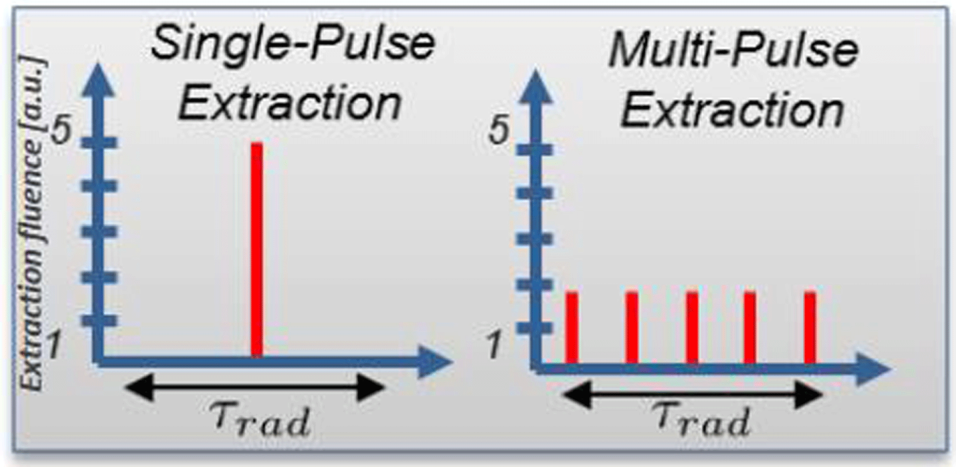
Figure 27. In MPE mode, the same stored energy is extracted from the gain medium over multiple, low-fluence pulses versus extracting the energy in a single, high-fluence pulse. The extraction time in the MPE mode must be less than the storage lifetime.
Figure 28. Left: Net efficiency (quantum defect $\times$
indirect CPA efficiency
$\times$
indirect CPA efficiency $\times$
electro-to-optical efficiency) versus gain lifetime of various laser gain media. For the Ti:sapphire case,
$\times$
electro-to-optical efficiency) versus gain lifetime of various laser gain media. For the Ti:sapphire case, $\unicode[STIX]{x1D702}_{\text{ICPA}}$
is 0.38 while for the other cases, which use direct CPA designs,
$\unicode[STIX]{x1D702}_{\text{ICPA}}$
is 0.38 while for the other cases, which use direct CPA designs, $\unicode[STIX]{x1D702}_{\text{ICPA}}$
is unity. Laser media were down-selected for net efficiency (
$\unicode[STIX]{x1D702}_{\text{ICPA}}$
is unity. Laser media were down-selected for net efficiency ( ${>}$
50%) and diode pumping suitability (gain lifetime
${>}$
50%) and diode pumping suitability (gain lifetime ${>}$
1 ms). Right: Extraction efficiency (stimulated emission rate divided by the sum of stimulated emission rate and spontaneous decay rate). In multi-pulse extraction, higher repetition rates (while maintaining the extraction fluence) are beneficial to the overall wall plug efficiency, i.e., the repetition rate determines the overall wall plug efficiency.
${>}$
1 ms). Right: Extraction efficiency (stimulated emission rate divided by the sum of stimulated emission rate and spontaneous decay rate). In multi-pulse extraction, higher repetition rates (while maintaining the extraction fluence) are beneficial to the overall wall plug efficiency, i.e., the repetition rate determines the overall wall plug efficiency.
∙ There is no need to pump within a single inverse lifetime, and therefore more efficient, much cheaper CW pump sources can be used that deliver the pump energy over a longer time.
∙ Because efficient extraction is not necessary in a single pulse, the extraction fluence is much reduced in the corresponding nonlinear phase as well.
∙ Broadband gain media that can be directly pumped by diode become accessible, therefore reducing the number of stages, the overall system complexity, and the number of loss stages.
MPE requires that the gain material has an inverse lifetime significantly less than the desired repetition rate. LLNL conducted a study with over 80 known laser gain media and analysed their suitability for maximum net efficiency, for laser diode pumping (long upper-state lifetime) and for lasing properties consistent with achieving high-peak power operation (100 TW to multi-petawatt).
As shown in Figure 28 (left) thulium (Tm)-doped gain media offer significant lifetime advantages over the well-established Yb-doped materials traditionally used for diode-pumped fibre and bulk systems. Thulium MPE becomes efficient at repetition rates ${>}$
3–5 kHz (see Figure 28 right). In comparison, ytterbium materials require repetition rates
${>}$
3–5 kHz (see Figure 28 right). In comparison, ytterbium materials require repetition rates ${>}$
50–100 kHz to operate efficiently or must be cryo-cooled. To be relevant for sub-100 fs applications, the gain bandwidth of thulium in the chosen laser host material must be
${>}$
50–100 kHz to operate efficiently or must be cryo-cooled. To be relevant for sub-100 fs applications, the gain bandwidth of thulium in the chosen laser host material must be ${>}$
50 nm, which is satisfied by most of the host materials.
${>}$
50 nm, which is satisfied by most of the host materials.
These considerations led to choosing Tm:YLF as the laser amplifier medium for a laser concept termed big aperture thulium (BAT) laser[Reference Haefner212, Reference Haefner213], shown in Figure 29, consistent with the requirements for secondary source generation, and specifically for an efficient laser for driving a laser wakefield accelerator (LWFA). The facility will deliver 300 kW at 30 J per pulse, but provides inherent through aperture (energy) and repetition rate (average power) flexibility for a variety of applications. For example, a 3 TW/1 MHz configuration would be of great interest for future high-repetition-rate X-ray FELs. Notably, higher wall-plug efficiencies can be achieved at the greater repetition rates.
Figure 29. LLNL’s BAT laser is envisioned to be capable of delivering up to 300 kW of 10 kHz, 30 J, 100 fs laser pulses.
The BAT system leverages the HAPLS baseline two-head helium gas-cooled four-pass amplifier design. It amplifies the short pulse directly in the primary laser chain using CPA, avoiding laser-pumped-laser architectures using indirect CPA (diode pumping of the pump laser) that have significantly higher energy loss inherently. Therefore, BAT can operate at electrical-to-optical efficiencies ${>}$
30% and true wall-plug efficiencies of
${>}$
30% and true wall-plug efficiencies of ${>}$
20%. It can be directly pumped by commercially available, standard and inexpensive CW laser diodes at
${>}$
20%. It can be directly pumped by commercially available, standard and inexpensive CW laser diodes at ${\sim}$
800 nm, making use of the 2-for-1 excited state quenching in thulium, eliminating the need for an additional laser system to deliver pump light to the final amplifier. Furthermore, through a cross-relaxation process it is possible to excite two thulium ions with a given pump photon, decreasing the effect of the quantum defect.
${\sim}$
800 nm, making use of the 2-for-1 excited state quenching in thulium, eliminating the need for an additional laser system to deliver pump light to the final amplifier. Furthermore, through a cross-relaxation process it is possible to excite two thulium ions with a given pump photon, decreasing the effect of the quantum defect.
Operating directly at $2~\unicode[STIX]{x03BC}\text{m}$
, BAT operates at reduced accumulated nonlinear phase retardation, or B-integral, which scales as
$2~\unicode[STIX]{x03BC}\text{m}$
, BAT operates at reduced accumulated nonlinear phase retardation, or B-integral, which scales as $1/\unicode[STIX]{x1D706}^{2}$
. Together with the wavelength scaling, the low-gain BAT architecture maintains a total B-integral
$1/\unicode[STIX]{x1D706}^{2}$
. Together with the wavelength scaling, the low-gain BAT architecture maintains a total B-integral ${<}$
0.1 in the amplifier. This low total B-integral, together with the relay-imaged architecture, produces high stability and high beam quality, and contributes to maintaining the high contrast of the front end through the power amplifier. The BAT laser is truly a CW laser: at any given time, there is more energy stored in the laser than extracted; hence the underlying laser and material physics are steady-state and continuous. This transition from pulsed operation to CW has already been exploited in high-average-power fibre lasers for many years.
${<}$
0.1 in the amplifier. This low total B-integral, together with the relay-imaged architecture, produces high stability and high beam quality, and contributes to maintaining the high contrast of the front end through the power amplifier. The BAT laser is truly a CW laser: at any given time, there is more energy stored in the laser than extracted; hence the underlying laser and material physics are steady-state and continuous. This transition from pulsed operation to CW has already been exploited in high-average-power fibre lasers for many years.
Significantly, key operating performances of a full-scale (300 kW) BAT can be effectively anchored on the performance of a ten-times-downscaled prototype BAT laser $(\text{miniBAT}=30~\text{kW})$
, with lower pulse energy and average power but identical fluences and identical thermal loading per unit area.
$(\text{miniBAT}=30~\text{kW})$
, with lower pulse energy and average power but identical fluences and identical thermal loading per unit area.
In addition to the desired petawatt class secondary source applications, the scalability of the system to higher pulse energy and average power at $2~\unicode[STIX]{x03BC}\text{m}$
also presents opportunities for additional applications in medicine, non-destructive evaluation, radiation testing, machining and other applications. Development of these new, very high average power technologies is underway at NIF&PS Advanced Photon Technologies Program.
$2~\unicode[STIX]{x03BC}\text{m}$
also presents opportunities for additional applications in medicine, non-destructive evaluation, radiation testing, machining and other applications. Development of these new, very high average power technologies is underway at NIF&PS Advanced Photon Technologies Program.
4.2.3 Cryo-HAP laser development
Cryogenic high-average-power (cryo-HAP) laser development is a proven route to meeting the demand for systems that can operate at high average powers while maintaining high energies, a prerequisite for a petawatt class laser system.
Cooling the gain media to cryogenic or close to cryogenic temperatures is a long-standing method for improving a number of critical parameters, including the thermal conductivity[Reference Slack and Oliver214, Reference Aggarwal, Ripin, Ochoa and Fan215] and absorption and emission cross-sections[Reference Dong, Bass, Mao, Deng and Gan216, Reference Brown, Cone, Sun and Equal217]. In 1998 Fan et al. reported[Reference Fan, Crow and Hoden218] on the improved properties of the then relatively new material, Yb:YAG, operating at cryogenic temperatures. These improvements were discussed between Yb:YAG operating at 300 and 100 K, and included a four-fold increase in thermal conductivity, reducing thermal lensing and stress-induced birefringence; in fact, they estimated that a system operating at 100 K possessed similar thermo-optic properties to one operating at 300 K, but at $1/15$
of the average power. Yb:YAG operates as a quasi-3-level laser at 300 K due to the high population of its lower laser level. At cryogenic temperatures the population in this lower level is significantly reduced, resulting in cryogenic Yb:YAG operating as a 4-level laser, reducing the lasing threshold, another significant benefit.
$1/15$
of the average power. Yb:YAG operates as a quasi-3-level laser at 300 K due to the high population of its lower laser level. At cryogenic temperatures the population in this lower level is significantly reduced, resulting in cryogenic Yb:YAG operating as a 4-level laser, reducing the lasing threshold, another significant benefit.
All of these benefits have resulted in a number of groups working on cryo-HAP laser systems based on differing amplifier architectures. For the purposes of this discussion we will define cryo-HAP systems as those that possess the potential to act as a pump or could be scaled to a level suitable for higher-average-power petawatt class operation, and therefore can operate ${\geqslant}1~\text{J}$
and
${\geqslant}1~\text{J}$
and ${\geqslant}10~\text{Hz}$
. The number of systems operating at these levels is not vast, with only a handful of successfully reported systems operating in this arena; the three architectures that have proven successful in this field are active mirror[Reference Liu, Banerjee, Zhang, Chen, Brown, Mills, Powers, Zhao, Golovin, Ghebregziabher and Umstadter73], the so-called TRAM[Reference Furuse, Kawanaka, Takeshita, Miyanaga, Saiki, Imasaki, Fujita and Ishii219] (total reflection active mirror) and multi-slab-based systems[Reference Mason, Fitton, Lintern, Banerjee, Ertel, Davenne, Hill, Blake, Phillips, Butcher, Smith, De Vido, Greenhalgh, Hernandez-Gomez and Collier220].
${\geqslant}10~\text{Hz}$
. The number of systems operating at these levels is not vast, with only a handful of successfully reported systems operating in this arena; the three architectures that have proven successful in this field are active mirror[Reference Liu, Banerjee, Zhang, Chen, Brown, Mills, Powers, Zhao, Golovin, Ghebregziabher and Umstadter73], the so-called TRAM[Reference Furuse, Kawanaka, Takeshita, Miyanaga, Saiki, Imasaki, Fujita and Ishii219] (total reflection active mirror) and multi-slab-based systems[Reference Mason, Fitton, Lintern, Banerjee, Ertel, Davenne, Hill, Blake, Phillips, Butcher, Smith, De Vido, Greenhalgh, Hernandez-Gomez and Collier220].
Active-mirror and TRAM systems typically populate the lower-energy space in this field, with energy currently limited to ${\sim}$
1 J. The active-mirror system is based on thin-disc laser architecture but uses a thick (
${\sim}$
1 J. The active-mirror system is based on thin-disc laser architecture but uses a thick ( ${\sim}$
5 mm) disc that is longitudinally cooled by liquid nitrogen flow across the rear face. This design has been shown capable of operation at 1.5 J, 500 Hz[Reference Baumgarten, Pedicone, Bravo, Wang, Yin, Menoni, Rocca and Reagan68] in a CPA-based scheme producing 5 ps pulses. The system was later tested at 1 J, 1 kHz[Reference Reagan, Baumgarten, Jankowska, Chi, Bravo, Dehne, Pedicone, Yin, Wang, Menoni and Rocca221]; however, at this power level thermal effects dominated, and resulted in a loss of energy after a short period of time. Further work aims to manage this increased thermal load and further scale the average power. The exception to the low-energy trend for active-mirror systems is the LUCIA laser system which is under development at LULI in France. This uses a cryogenically cooled active-mirror design and has been successfully operated at 14 J, 2 Hz[Reference Gonçalvès-Novo, Albach, Vincent, Arzakantsyan and Chanteloup222].
${\sim}$
5 mm) disc that is longitudinally cooled by liquid nitrogen flow across the rear face. This design has been shown capable of operation at 1.5 J, 500 Hz[Reference Baumgarten, Pedicone, Bravo, Wang, Yin, Menoni, Rocca and Reagan68] in a CPA-based scheme producing 5 ps pulses. The system was later tested at 1 J, 1 kHz[Reference Reagan, Baumgarten, Jankowska, Chi, Bravo, Dehne, Pedicone, Yin, Wang, Menoni and Rocca221]; however, at this power level thermal effects dominated, and resulted in a loss of energy after a short period of time. Further work aims to manage this increased thermal load and further scale the average power. The exception to the low-energy trend for active-mirror systems is the LUCIA laser system which is under development at LULI in France. This uses a cryogenically cooled active-mirror design and has been successfully operated at 14 J, 2 Hz[Reference Gonçalvès-Novo, Albach, Vincent, Arzakantsyan and Chanteloup222].
The TRAM design was proposed in 2009[Reference Furuse, Kawanaka, Takeshita, Miyanaga, Saiki, Imasaki, Fujita and Ishii219] as an extension to the active-mirror scheme that sees a thin ( ${\sim}200~\unicode[STIX]{x03BC}\text{m}$
) layer of Yb:YAG bonded to a trapezoidal undoped YAG prism. The pump and laser light enters the anti-reflection-coated side of the prism and is totally internally reflected at the rear face of the Yb:YAG layer, removing the requirement for a high reflective coating that could become damaged by higher-power operation. As with the active-mirror design, the TRAM is cryogenically cooled directly on the rear face of the Yb:YAG substrate. The TRAM architecture has been reported to operate at 1 J, 10 Hz with a design upgrade to 100 Hz operation well underway[Reference Divoky, Tokita, Hwang, Kawashima, Kan, Lucianetti, Mocek and Kawanaka223]. It is to be used as part of the front end system for the GENBU laser concept developed at ILE, Osaka University in Japan[Reference Kawanaka, Miyanaga, Tsubakimoto, Jitsuno, Nakatsuka, Izawa, Yasuhara and Kawashima224].
${\sim}200~\unicode[STIX]{x03BC}\text{m}$
) layer of Yb:YAG bonded to a trapezoidal undoped YAG prism. The pump and laser light enters the anti-reflection-coated side of the prism and is totally internally reflected at the rear face of the Yb:YAG layer, removing the requirement for a high reflective coating that could become damaged by higher-power operation. As with the active-mirror design, the TRAM is cryogenically cooled directly on the rear face of the Yb:YAG substrate. The TRAM architecture has been reported to operate at 1 J, 10 Hz with a design upgrade to 100 Hz operation well underway[Reference Divoky, Tokita, Hwang, Kawashima, Kan, Lucianetti, Mocek and Kawanaka223]. It is to be used as part of the front end system for the GENBU laser concept developed at ILE, Osaka University in Japan[Reference Kawanaka, Miyanaga, Tsubakimoto, Jitsuno, Nakatsuka, Izawa, Yasuhara and Kawashima224].
To date, the highest reported energy from a cryo-HAP system has been achieved using multi-slab architectures. Of these the DiPOLE 100 system produced by the UK’s Central Laser Facility is currently the only one to achieve 1 kW operation, with 100 J pulse energies at 10 Hz[Reference Kawanaka, Miyanaga, Tsubakimoto, Jitsuno, Nakatsuka, Izawa, Yasuhara and Kawashima224]. DIPOLE uses ceramic Yb:YAG amplifier slabs. A general schematic of the interior of the DiPOLE cryo-amplifier head is shown in Figure 30. The gain media slabs are mounted in aerodynamic titanium vanes and housed within a vacuum insulated pressure vessel. The doping concentration of the slabs is graded to provide uniform absorption of the pump energy, resulting in a uniformly distributed thermal load. High-pressure cryogenically cooled helium gas at 150 K flows over the slabs to remove the waste heat.

Figure 30. Schematic of the DiPOLE cryo-amplifier concept. Graded index Yb:YAG ceramic slabs are cooled to cryogenic temperatures (150 K) using a high-pressure, high-speed cryogenically cooled helium flow.
The PENELOPE laser also uses the He-gas-cooling architecture for cryogenic cooling in its main amplifier[Reference Roso111]; however, as it is designed as a CPA system the gain media of choice must support a broad bandwidth. As a result Yb:CaF2 is used in place of Yb:YAG and the system is not cooled below 200 K in order to preserve bandwidth. It should be noted that PENELOPE’s design repetition rate is 1 Hz but is included here as by itself is a petawatt class system. Hamamatsu Photonics has also reported on the successful operation of a 100 J class narrowband multi-slab system[Reference Sekine, Takeuchi, Kurita, Hatano, Muramatsu, Mizuta, Kabeya, Tamaoki and Kato225]. The main amplifier uses Yb:YAG slabs that are edge-cooled by two cryostats above and below the gain media. This system has achieved output energies of 55 J but is currently not operating at its design repetition rate of 10 Hz.
It should be noted that there are examples of high-average-power systems operating at high pulse energies that do not operate at cryogenic temperatures. The most notable examples are the HAPLS system[Reference Hornung, Liebetrau, Seidel, Keppler, Kessler, Körner, Hellwing, Schorcht, Klöpfel, Arunachalam, Becker, Sävert, Polz, Hein and Kaluza226] developed by LLNL and the POLARIS system[Reference Haefner, Bayramian, Betts, Bopp, Buck, Cupal, Drouin, Erlandson, Horáček, Horner, Jarboe, Kasl, Kim, Koh, Koubíková, Maranville, Marshall, Mason, Menapace, Miller, Mazurek, Naylon, Novák, Peceli, Rosso, Schaffers, Sistrunk, Smith, Spinka, Stanley, Steele, Stolz, Suratwala, Telford, Thoma, VanBlarcom, Weiss and Wegner41] at Jena.
To date, the highest reported performance of a cryo-HAP system is operation at the 1 kW level. This has been achieved by an active mirror, at low energies, and a slab system at high energies. If we consider that a high-average-power petawatt class system would require at least tens of joules of energy then the likely candidate for further increases in average power is the slab-based architecture. Such development work has already started at the Central Laser Facility, on a collaborative project with the HiLASE Centre, Czech Republic to increase the repetition rate of DiPOLE systems to 100 Hz. This would be at the 10 J level, with a view to future scaling of the energy where practicable. Such a system would be capable of driving a short-pulse laser at the 100–200 TW level at 100 Hz.
To summarize, gas-cooled HAP laser systems are already operating well above what flashlamp systems can provide and, in the coming years as the technology matures, they will be capable of significantly increasing the average power.
4.2.4 Coherent beam combining
To achieve both high-peak and high-average powers simultaneously might become a reality thanks to a relatively recent[Reference Fan227] laser architectural approach called coherent beam combining (CBC). Although underlying advanced technology is necessary, the CBC concept can be described in quite simple words: it basically consists in the spatial splitting of an initial laser beam into $N$
sub-beams prior to amplification, followed by subsequent recombination of the amplified beams. The very large majority of ongoing laser physics research in CBC relies on fibre-based amplifiers. Indeed, the high geometrical aspect ratio of such amplifiers makes it a solution of choice for high-average-power operation requiring extremely efficient thermal management. Fibre-based CBC allows the distribution of power scaling challenges across multiple optical channels to overcome different physical limitations such as average power-related effects like mode instabilities[Reference Smith and Smith228, Reference Jauregui, Limpert and Tünnermann229], but also nonlinear pulse-energy- and peak-power-related effects.
$N$
sub-beams prior to amplification, followed by subsequent recombination of the amplified beams. The very large majority of ongoing laser physics research in CBC relies on fibre-based amplifiers. Indeed, the high geometrical aspect ratio of such amplifiers makes it a solution of choice for high-average-power operation requiring extremely efficient thermal management. Fibre-based CBC allows the distribution of power scaling challenges across multiple optical channels to overcome different physical limitations such as average power-related effects like mode instabilities[Reference Smith and Smith228, Reference Jauregui, Limpert and Tünnermann229], but also nonlinear pulse-energy- and peak-power-related effects.
To date, the highest peak power ( ${\sim}$
45 GW) was achieved by the IAP-HIJ, Jena, Germany team: 12 mJ pulse energy with 700 W average power and 262 fs pulse duration have been obtained with eight parallel channels and four temporal pulse replicas[Reference Kienel, Müller, Klenke, Limpert and Tünnermann230]. Recently[Reference Mueller, Klenke, Stark, Buldt, Gottschall, Tünnermann and Limpert231], the same team presented operations at about 2 kW average power with 16 channels (2.3 mJ) (Figure 31). Future activities will consider a 32-channel system, also relying on rod-type large-pitch fibre amplifiers[Reference Limpert, Stutzki, Jansen, Otto, Eidam, Jauregui and Tünnermann232]. In addition, a four-channel ytterbium fibre femtosecond CPA system with 3.5 kW average power has been demonstrated[Reference Müller, Klenke, Steinkopff, Stark, Tünnermann and Limpert233]. These performances have been achieved through a filled-aperture configuration, a near-field combination approach allowing a high efficiency (theoretically 100%, in most demonstrations well above 90%) but involving multiple combining elements in cascade, so that the system complexity increases with the number of fibres, somewhat limiting its scalability potential. To overcome this issue, the same team is also exploring multicore fibres with segmented mirror splitters[Reference Klenke, Müller, Stark, Stutzki, Hupel, Schreiber, Tünnermann and Limpert234], an interesting approach on the journey to highly parallel CBC systems requiring hundreds/thousands of channels. The idea is to decouple the component count from the channel count, here by a factor of sixteen since this is the number of embedded channels within a single fibre. Future developments will concentrate on increasing the core number per fibre, that will enable joule-class pulse energy at tens of kHz repetition rates from a single fibre.
${\sim}$
45 GW) was achieved by the IAP-HIJ, Jena, Germany team: 12 mJ pulse energy with 700 W average power and 262 fs pulse duration have been obtained with eight parallel channels and four temporal pulse replicas[Reference Kienel, Müller, Klenke, Limpert and Tünnermann230]. Recently[Reference Mueller, Klenke, Stark, Buldt, Gottschall, Tünnermann and Limpert231], the same team presented operations at about 2 kW average power with 16 channels (2.3 mJ) (Figure 31). Future activities will consider a 32-channel system, also relying on rod-type large-pitch fibre amplifiers[Reference Limpert, Stutzki, Jansen, Otto, Eidam, Jauregui and Tünnermann232]. In addition, a four-channel ytterbium fibre femtosecond CPA system with 3.5 kW average power has been demonstrated[Reference Müller, Klenke, Steinkopff, Stark, Tünnermann and Limpert233]. These performances have been achieved through a filled-aperture configuration, a near-field combination approach allowing a high efficiency (theoretically 100%, in most demonstrations well above 90%) but involving multiple combining elements in cascade, so that the system complexity increases with the number of fibres, somewhat limiting its scalability potential. To overcome this issue, the same team is also exploring multicore fibres with segmented mirror splitters[Reference Klenke, Müller, Stark, Stutzki, Hupel, Schreiber, Tünnermann and Limpert234], an interesting approach on the journey to highly parallel CBC systems requiring hundreds/thousands of channels. The idea is to decouple the component count from the channel count, here by a factor of sixteen since this is the number of embedded channels within a single fibre. Future developments will concentrate on increasing the core number per fibre, that will enable joule-class pulse energy at tens of kHz repetition rates from a single fibre.
Figure 31. Jena 16-channel filled aperture system.
With this in mind, the highest scalable architecture, XCAN project, Ecole Polytechnique-Thales, Palaiseau, France team is developing a 61-channel prototype (Figure 32) relying on tiled apertures allowing single step far-field combination. The advantage of this method is that there is no actual beam combining element and therefore no power scaling limitation, but the combining efficiency is theoretically limited to about 65% due to the multi-aperture Fourier losses. XCAN recently demonstrated[Reference Heilmann, Le Dortz, Daniault, Fsaifes, Bellanger, Bourderionnet, Larat, Lallier, Antier, Durand, Simon-Boisson, Brignon and Chanteloup235] operation of the first 7 channels with 45% combination efficiency and 70 W average power using $30~\unicode[STIX]{x03BC}\text{m}$
MFD (mode field diameter) fibre amplifiers. The tiled-aperture approach appears most promising to combine 10,000 channels at unprecedented power levels.
$30~\unicode[STIX]{x03BC}\text{m}$
MFD (mode field diameter) fibre amplifiers. The tiled-aperture approach appears most promising to combine 10,000 channels at unprecedented power levels.
These demonstrations pave the way towards a system required for applications ranging from particle accelerators and nuclear waste transmutation to space debris tracking and mitigation[Reference Mourou, Brocklesby, Toshiki and Limpert236, Reference Quinn, Jukna, Ebisuzaki, Dicaire, Soulard, Summerer, Couairon and Mourou237] in the near future.

Figure 32. Palaiseau XCAN tiled-aperture system: Yb-doped fibres fluorescence for 19 out of 61 channels. Insert: laserhead with 35 fibres inserted.
4.2.5 Time-domain pulse combining
Coherent spatial beam combining of multiple fibre laser apertures overcomes limitations of individual fibres, and thus enables scaling of the total energy and power, but it does so at the cost of requiring a very large number of parallel channels in a fibre laser array. This is due to the limited energies that are achievable with a fibre-based CPA system. Relatively small beam size and long signal propagation length in a fibre lead to strong nonlinear effects, which confine typical fibre CPA energies to the $100~\unicode[STIX]{x03BC}\text{J}$
to 1 mJ range; for fibre core sizes between
$100~\unicode[STIX]{x03BC}\text{J}$
to 1 mJ range; for fibre core sizes between $30~\unicode[STIX]{x03BC}\text{m}$
and
$30~\unicode[STIX]{x03BC}\text{m}$
and $100~\unicode[STIX]{x03BC}\text{m}$
, respectively[Reference Galvanauskas, Cho, Hariharan, Fermann and Harter238–Reference Eidam, Rothhardt, Stutzki, Jansen, Hädrich, Carstens, Jauregui, Limpert and Tünnermann240]. Hence, reaching 1 J of pulse energy should need between 1000 and 10,000 fibre amplification channels and combined beams[Reference Gaida, Kienel, Müller, Klenke, Gebhardt, Stutzki, Jauregui, Limpert and Tünnermann241]. Technical challenges and costs associated with such large arrays are very substantial; however, actual stored energies in optical fibres are much higher, exceeding fibre CPA results by approximately two orders of magnitude. This highlights the potential of an approximately hundred times reduction in fibre array size, which would have enormous practical impact on reducing system size, cost and complexity.
$100~\unicode[STIX]{x03BC}\text{m}$
, respectively[Reference Galvanauskas, Cho, Hariharan, Fermann and Harter238–Reference Eidam, Rothhardt, Stutzki, Jansen, Hädrich, Carstens, Jauregui, Limpert and Tünnermann240]. Hence, reaching 1 J of pulse energy should need between 1000 and 10,000 fibre amplification channels and combined beams[Reference Gaida, Kienel, Müller, Klenke, Gebhardt, Stutzki, Jauregui, Limpert and Tünnermann241]. Technical challenges and costs associated with such large arrays are very substantial; however, actual stored energies in optical fibres are much higher, exceeding fibre CPA results by approximately two orders of magnitude. This highlights the potential of an approximately hundred times reduction in fibre array size, which would have enormous practical impact on reducing system size, cost and complexity.
Low fibre CPA energies are the result of the fundamental limits on CPA-stretched pulse durations, which cannot exceed a nanosecond range. In solid-state CPA systems, such as Ti:sapphire, large-transverse-aperture crystals can be used to additionally increase CPA energies by a couple of orders of magnitude to reach the full stored energy. Since fibre lasers have constrained transverse apertures, full stored energy can only be accessed by exploiting the time domain – for example, by using coherent pulse combining to artificially extend amplified pulse durations from a nanosecond to at least the hundreds of nanoseconds range.
Recently, a near-complete energy extraction from a fibre amplifier has been achieved using the so-called coherent pulse stacking amplification (CPSA) technique at the University of Michigan, US[Reference Zhou, Ruppe, Zhu, Hu, Nees and Galvanauskas242]. In the latest experiments[Reference Pei, Ruppe, Chen, Sheikhsofla, Nees, Yang, Wilcox, Leemans and Galvanauskas243] a sequence of 81 pulses, each stretched to ${\sim}$
1 ns to provide an approximately 80 ns effective pulse duration, was formed, amplified and coherently time-combined into a single pulse, which was compressed down to
${\sim}$
1 ns to provide an approximately 80 ns effective pulse duration, was formed, amplified and coherently time-combined into a single pulse, which was compressed down to ${\sim}$
500 fs. This CPSA system, based on an
${\sim}$
500 fs. This CPSA system, based on an $85~\unicode[STIX]{x03BC}\text{m}$
core CCC (chirally coupled core) fibre amplifier[Reference Pei, Ruppe, Chen, Sheikhsofla, Nees, Yang, Wilcox, Leemans and Galvanauskas243, Reference Ma, Zhu, Hu, Kaplan and Galvanauskas244], achieved 10.5 mJ energy extraction with only 4.5 radians of accumulated nonlinear phase, which is more than 90% of the measured stored energy.
$85~\unicode[STIX]{x03BC}\text{m}$
core CCC (chirally coupled core) fibre amplifier[Reference Pei, Ruppe, Chen, Sheikhsofla, Nees, Yang, Wilcox, Leemans and Galvanauskas243, Reference Ma, Zhu, Hu, Kaplan and Galvanauskas244], achieved 10.5 mJ energy extraction with only 4.5 radians of accumulated nonlinear phase, which is more than 90% of the measured stored energy.
The CPSA approach illustrated in Figure 33 consists of two principal parts: monolithically integrated electronic shaping of the stacking-burst sequence at the system’s front; and a compact free-space pulse stacking arrangement at the system’s end constructed using Gires–Tournois interferometer (GTI) cavities. The purpose of the electronic shaping is two-fold. First, its phase modulates each individual pulse in the stacking-burst sequence to enable, and to control, its stacking in the GTI-based arrangement at the system’s output. Second, since the final amplification stages operate at near-complete energy extraction, it is necessary to control the stacking-burst amplitude profile to offset temporal-shape distortions caused by severe saturation of these stages. This electronic control is implemented using a pair of fibre-pigtailed fast electro-optic modulators, the amplitude modulator in the pair being used to carve out the required burst shape directly from the mode-locked oscillator periodic pulse train, and the phase modulator to imprint the required optical phase on each of the pulses in the burst. Such an arrangement is monolithically integrated, and therefore is very compact. Most importantly, it provides all the degrees of freedom in temporal-shape control needed for completely offsetting the reshaping in strongly saturated amplifiers.
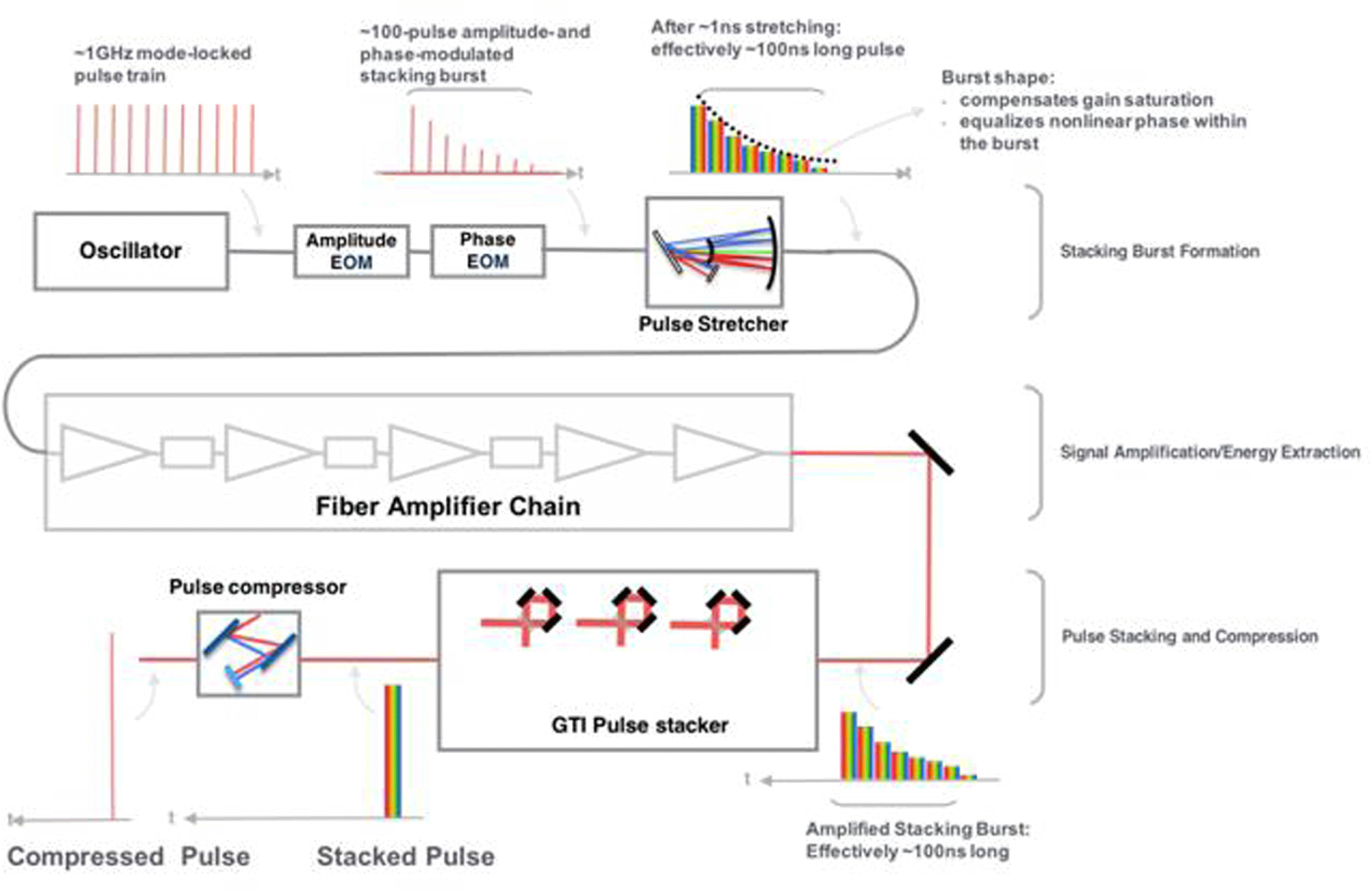
Figure 33. Coherent pulse stacking amplification (CPSA).

Figure 34. Divided pulse amplification (DPA).
A different time-domain pulse combining technique, the so-called divided pulse amplification (DPA), has also been demonstrated both at Amplitude Systems, France and at the Helmholtz Institute Jena, Germany[Reference Zaouter, Guichard, Daniault, Hanna, Morin, Hönninger, Mottay, Druon and Georges245, Reference Kienel, Klenke, Eidam, Hädrich, Limpert and Tünnermann246]. In this DPA technique, illustrated in Figure 34, linear delay lines are used to produce several sequential replicas of the stretched pulse, which after the amplification are recombined back to a single pulse using an identical delay-line arrangement[Reference Zaouter, Guichard, Daniault, Hanna, Morin, Hönninger, Mottay, Druon and Georges245, Reference Kienel, Klenke, Eidam, Hädrich, Limpert and Tünnermann246]. DPA is typically used to produce two to four stretched pulse replicas, resulting in a similar improvement in the extracted pulse energies, with experimentally demonstrated energies in the 1–2 mJ range. In conjunction with coherent beam combination of eight parallel fibre amplifiers, this approach allows for the generation of 12 mJ pulses with 262 fs pulse duration[Reference Galloway, Popmintchev, Pisanty, Hickstein, Murnane, Kapteyn and Popmintchev247]. However, the further enhancement of the energy extraction achievable with DPA is limited, which is mainly associated with the fact that the opto-mechanical arrangement used for pulse splitting offers insufficient degrees of freedom for arbitrary pulse-burst shape control. Thus, the compensation of gain saturation effects of longer sequences of pulses is limited. However, a novel approach named electro-optically controlled DPA, which is based on a fibre-integrated front end for pulse-burst generation, offers sufficient degrees of freedom to arbitrarily scale the number of pulses[Reference Stark, Müller, Kienel, Klenke, Limpert and Tünnermann248]. In a first proof-of-principle demonstration, the temporal combination of up to eight pulses allowed high temporal contrast and high combination efficiency of about 90%[Reference Stark, Müller, Kienel, Klenke, Limpert and Tünnermann248]. Subsequent experiments with this technique, now involving a high-power ultrafast fibre laser system and an improved low-footprint setup for pulse combination, were carried out recently and have already led to promising initial results at mJ pulse energy levels[Reference Stark, Buldt, Müller, Klenke, Tünnermann and Limpert249].

Figure 35. (a) Collinear phase-matching. (b) Conventional wavelength-insensitive non-collinear phase-matching. (c) Temperature-insensitive non-collinear phase-matching with signal angular dispersion. The second rows in (a) to (c) show the normalized gain versus temperature and wavelength. (d) Measured signal efficiency versus temperature deviation for several non-collinear angles. $\unicode[STIX]{x1D6FC}=5.8^{\circ }$
and
$\unicode[STIX]{x1D6FC}=5.8^{\circ }$
and $6.8^{\circ }$
correspond to non-collinear phase-matching with signal angular dispersion, while
$6.8^{\circ }$
correspond to non-collinear phase-matching with signal angular dispersion, while $\unicode[STIX]{x1D6FC}=1.2^{\circ }$
corresponds to wavelength-insensitive non-collinear phase-matching. (e) Measured spectra of amplified signals with different amounts of angular dispersion when
$\unicode[STIX]{x1D6FC}=1.2^{\circ }$
corresponds to wavelength-insensitive non-collinear phase-matching. (e) Measured spectra of amplified signals with different amounts of angular dispersion when $\unicode[STIX]{x1D6FC}=5.8^{\circ }$
.
$\unicode[STIX]{x1D6FC}=5.8^{\circ }$
.
4.2.6 Temperature-insensitive OPCPA
Owing to the inevitable thermal effects at a high repetition rate, OPCPA with simultaneous high-peak and average powers is a challenge to laser technology[Reference Rothhardt, Demmler, Hädrich, Peschel, Limpert and Tünnermann250]. The temperature distortion in an OPCPA crystal will cause thermal dephasing ( $\unicode[STIX]{x0394}k=k_{p}-k_{s}-k_{i}\neq 0$
, where
$\unicode[STIX]{x0394}k=k_{p}-k_{s}-k_{i}\neq 0$
, where $k_{p}$
,
$k_{p}$
, $k_{s}$
and
$k_{s}$
and $k_{i}$
are the wave-vectors of the pump, signal and idler waves in Figure 35(a), respectively) and further degrade the conversion efficiency and the spatiotemporal quality of output pulses. The state-of-the-art OPCPA technique has produced an average power of 88 W in a normal mode[Reference Mecseki, Windeler, Miahnahri, Robinson, Fraser, Fry and Tavella251], and 112 W in a burst mode[Reference Höppner, Hage, Tanikawa, Schulz, Riedel, Teubner, Prandolini, Faatz and Tavella252]. It is crucial to overcome the thermal dephasing problem in high-average-power OPCPAs.
$k_{i}$
are the wave-vectors of the pump, signal and idler waves in Figure 35(a), respectively) and further degrade the conversion efficiency and the spatiotemporal quality of output pulses. The state-of-the-art OPCPA technique has produced an average power of 88 W in a normal mode[Reference Mecseki, Windeler, Miahnahri, Robinson, Fraser, Fry and Tavella251], and 112 W in a burst mode[Reference Höppner, Hage, Tanikawa, Schulz, Riedel, Teubner, Prandolini, Faatz and Tavella252]. It is crucial to overcome the thermal dephasing problem in high-average-power OPCPAs.
The phase-matching condition is a major factor that governs nonlinear parametric processes. To enlarge the phase-matching temperature acceptance in second-harmonic generation (SHG), one can select a specific nonlinear crystal with $\unicode[STIX]{x2202}\unicode[STIX]{x0394}k/\unicode[STIX]{x2202}T=0$
[Reference Barker, Eimerl and Velsko253] or combine two different crystals with opposite signs of
$\unicode[STIX]{x2202}\unicode[STIX]{x0394}k/\unicode[STIX]{x2202}T=0$
[Reference Barker, Eimerl and Velsko253] or combine two different crystals with opposite signs of $\unicode[STIX]{x2202}\unicode[STIX]{x0394}k/\unicode[STIX]{x2202}T$
[Reference Zhong, Yuan, Zhu and Qian254]. These methods, however, will not be effective in OPCPA that requires broadband phase-matching simultaneously.
$\unicode[STIX]{x2202}\unicode[STIX]{x0394}k/\unicode[STIX]{x2202}T$
[Reference Zhong, Yuan, Zhu and Qian254]. These methods, however, will not be effective in OPCPA that requires broadband phase-matching simultaneously.
With this in mind a new phase-matching design of OPCPA has been proposed at Shanghai Jiao Tong University, China. The non-collinear OPCPA configuration was previously devoted to achieving wavelength-insensitive phase-matching $(\unicode[STIX]{x2202}\unicode[STIX]{x0394}k/\unicode[STIX]{x2202}\unicode[STIX]{x1D706}=0)$
with a large spectral bandwidth (Figure 35(b)). Notably, it was recently found that the non-collinear phase-matching configuration can also make OPCPA insensitive to temperature
$(\unicode[STIX]{x2202}\unicode[STIX]{x0394}k/\unicode[STIX]{x2202}\unicode[STIX]{x1D706}=0)$
with a large spectral bandwidth (Figure 35(b)). Notably, it was recently found that the non-collinear phase-matching configuration can also make OPCPA insensitive to temperature $(\unicode[STIX]{x2202}\unicode[STIX]{x0394}k/\unicode[STIX]{x2202}T=0)$
by setting an appropriate non-collinear angle
$(\unicode[STIX]{x2202}\unicode[STIX]{x0394}k/\unicode[STIX]{x2202}T=0)$
by setting an appropriate non-collinear angle $\unicode[STIX]{x1D6FC}$
[Reference Tang, Ma, Wang, Zhou, Xie, Yuan, Zhu and Qian255]. In an LBO-crystal-based OPCPA with
$\unicode[STIX]{x1D6FC}$
[Reference Tang, Ma, Wang, Zhou, Xie, Yuan, Zhu and Qian255]. In an LBO-crystal-based OPCPA with $\unicode[STIX]{x1D706}_{p}=532~\text{nm}$
and
$\unicode[STIX]{x1D706}_{p}=532~\text{nm}$
and $\unicode[STIX]{x1D706}_{s}=800~\text{nm}$
, the non-collinear phase-matching can be designed for either
$\unicode[STIX]{x1D706}_{s}=800~\text{nm}$
, the non-collinear phase-matching can be designed for either $\unicode[STIX]{x2202}\unicode[STIX]{x0394}k/\unicode[STIX]{x2202}T=0$
with
$\unicode[STIX]{x2202}\unicode[STIX]{x0394}k/\unicode[STIX]{x2202}T=0$
with $\unicode[STIX]{x1D6FC}=5.8^{\circ }$
or
$\unicode[STIX]{x1D6FC}=5.8^{\circ }$
or $\unicode[STIX]{x2202}\unicode[STIX]{x0394}k/\unicode[STIX]{x2202}\unicode[STIX]{x1D706}=0$
with
$\unicode[STIX]{x2202}\unicode[STIX]{x0394}k/\unicode[STIX]{x2202}\unicode[STIX]{x1D706}=0$
with $\unicode[STIX]{x1D6FC}=1.2^{\circ }$
. The non-collinear phase-matching with
$\unicode[STIX]{x1D6FC}=1.2^{\circ }$
. The non-collinear phase-matching with $\unicode[STIX]{x1D6FC}=5.8^{\circ }$
has a temperature acceptance six times larger than that at
$\unicode[STIX]{x1D6FC}=5.8^{\circ }$
has a temperature acceptance six times larger than that at $\unicode[STIX]{x1D6FC}=1.2^{\circ }$
(Figure 35(d)). As these two non-collinear angles are not equal, angular dispersion on the seed signal must be introduced to ensure
$\unicode[STIX]{x1D6FC}=1.2^{\circ }$
(Figure 35(d)). As these two non-collinear angles are not equal, angular dispersion on the seed signal must be introduced to ensure $\unicode[STIX]{x2202}\unicode[STIX]{x0394}k/\unicode[STIX]{x2202}\unicode[STIX]{x1D706}=0$
in the temperature-insensitive non-collinear phase-matching with
$\unicode[STIX]{x2202}\unicode[STIX]{x0394}k/\unicode[STIX]{x2202}\unicode[STIX]{x1D706}=0$
in the temperature-insensitive non-collinear phase-matching with $\unicode[STIX]{x1D6FC}=5.8^{\circ }$
(Figure 35(c)). In a proof-of-principle experiment with a signal angular dispersion of
$\unicode[STIX]{x1D6FC}=5.8^{\circ }$
(Figure 35(c)). In a proof-of-principle experiment with a signal angular dispersion of $350~\unicode[STIX]{x03BC}\text{rad}/\text{nm}$
, the spectral bandwidth of temperature-insensitive non-collinear phase-matching can be as large as that of the conventional wavelength-insensitive non-collinear phase-matching (Figure 35(e)).
$350~\unicode[STIX]{x03BC}\text{rad}/\text{nm}$
, the spectral bandwidth of temperature-insensitive non-collinear phase-matching can be as large as that of the conventional wavelength-insensitive non-collinear phase-matching (Figure 35(e)).
Furthermore, simultaneous wavelength and temperature-insensitive phase-matching, without the need of additional angular dispersion at seed signal, can be realized if the two non-collinear angles for $\unicode[STIX]{x2202}\unicode[STIX]{x0394}k/\unicode[STIX]{x2202}\unicode[STIX]{x1D706}=0$
and
$\unicode[STIX]{x2202}\unicode[STIX]{x0394}k/\unicode[STIX]{x2202}\unicode[STIX]{x1D706}=0$
and $\unicode[STIX]{x2202}\unicode[STIX]{x0394}k/\unicode[STIX]{x2202}T=0$
coincide with each other. This can be achieved by properly designing the reference temperature for the crystal[Reference Tang, Wang, Ma, Zhou, Yuan, Xie and Qian256]. In an LBO-crystal-based OPCPA with
$\unicode[STIX]{x2202}\unicode[STIX]{x0394}k/\unicode[STIX]{x2202}T=0$
coincide with each other. This can be achieved by properly designing the reference temperature for the crystal[Reference Tang, Wang, Ma, Zhou, Yuan, Xie and Qian256]. In an LBO-crystal-based OPCPA with $\unicode[STIX]{x1D706}_{p}=355~\text{nm}$
and
$\unicode[STIX]{x1D706}_{p}=355~\text{nm}$
and $\unicode[STIX]{x1D706}_{s}=550~\text{nm}$
, the two non-collinear angles for
$\unicode[STIX]{x1D706}_{s}=550~\text{nm}$
, the two non-collinear angles for $\unicode[STIX]{x2202}\unicode[STIX]{x0394}k/\unicode[STIX]{x2202}T=0$
and
$\unicode[STIX]{x2202}\unicode[STIX]{x0394}k/\unicode[STIX]{x2202}T=0$
and $\unicode[STIX]{x2202}\unicode[STIX]{x0394}k/\unicode[STIX]{x2202}\unicode[STIX]{x1D706}=0$
are equal to each other
$\unicode[STIX]{x2202}\unicode[STIX]{x0394}k/\unicode[STIX]{x2202}\unicode[STIX]{x1D706}=0$
are equal to each other $(\unicode[STIX]{x1D6FC}=3.6^{\circ })$
at the crystal reference temperature of 337 K. As a result, the spectral bandwidth of such an OPCPA phase-matching design was similar to that
$(\unicode[STIX]{x1D6FC}=3.6^{\circ })$
at the crystal reference temperature of 337 K. As a result, the spectral bandwidth of such an OPCPA phase-matching design was similar to that $(\unicode[STIX]{x0394}\unicode[STIX]{x1D706}\cong 90~\text{nm})$
in conventional wavelength-insensitive non-collinear phase-matching, while the temperature acceptance
$(\unicode[STIX]{x0394}\unicode[STIX]{x1D706}\cong 90~\text{nm})$
in conventional wavelength-insensitive non-collinear phase-matching, while the temperature acceptance $(\unicode[STIX]{x0394}T\cong 40~\text{K})$
was increased by a factor of 4.3. Due to its ability to simultaneously support broadband amplification and large temperature bandwidth, the temperature-insensitive OPCPA design may provide a promising way to generate ultra-intense lasers with kW average powers[Reference Tang, Ma, Wang, Zhou, Xie, Yuan, Zhu and Qian255, Reference Tang, Wang, Ma, Zhou, Yuan, Xie and Qian256].
$(\unicode[STIX]{x0394}T\cong 40~\text{K})$
was increased by a factor of 4.3. Due to its ability to simultaneously support broadband amplification and large temperature bandwidth, the temperature-insensitive OPCPA design may provide a promising way to generate ultra-intense lasers with kW average powers[Reference Tang, Ma, Wang, Zhou, Xie, Yuan, Zhu and Qian255, Reference Tang, Wang, Ma, Zhou, Yuan, Xie and Qian256].
4.3 Enabling technologies
The route to ever-increasing laser powers, coupled with a desire to operate these facilities at higher repetition rates, requires a number of key technologies. In this section we look at some of these technologies and the challenges facing their development.
∙ The development of mid-infrared lasers
∙ Improvements in temporal contrast
∙ Plasma optics
∙ Grand challenges
○ Advanced optics
○ Laser diagnostics
○ Plasma diagnostics
○ Target fabrication.
4.3.1 The development of mid-infrared lasers
Most ultra-intense lasers available today operate at wavelengths around one micron. The reason is that the shortest pulses are offered by Ti:sapphire lasers whereas the highest pulse energies are possible with neodymium- and ytterbium-doped materials. Moreover, many passive optical materials with high transparency can be found in the near-infrared (NIR) and there is typically no issue from molecular vibration absorption from the normal atmosphere in this range. The classification of the infrared wavelength regions is often inconsistent. Here we will use the term mid-infrared (MIR) for all wavelengths above about $1.7~\unicode[STIX]{x03BC}\text{m}$
to about
$1.7~\unicode[STIX]{x03BC}\text{m}$
to about $15~\unicode[STIX]{x03BC}\text{m}$
, even so it is often further split into short- (SWIR), mid- (MWIR) and long-wavelength infrared (LWIR).
$15~\unicode[STIX]{x03BC}\text{m}$
, even so it is often further split into short- (SWIR), mid- (MWIR) and long-wavelength infrared (LWIR).
Many applications of ultra-intense lasers would greatly benefit from wavelengths longer than those available around one micron. This is not obvious since intensity scales with the wavelength $\unicode[STIX]{x1D706}$
as
$\unicode[STIX]{x1D706}$
as $1/\unicode[STIX]{x1D706}^{3}$
, the pulse length with
$1/\unicode[STIX]{x1D706}^{3}$
, the pulse length with $1/\unicode[STIX]{x1D706}$
and the focusability with
$1/\unicode[STIX]{x1D706}$
and the focusability with $1/\unicode[STIX]{x1D706}^{2}$
. But laser–matter interaction can only be proportional to intensity
$1/\unicode[STIX]{x1D706}^{2}$
. But laser–matter interaction can only be proportional to intensity $I$
if they are always constrained to the same number of field oscillations. If this is not the case, the interaction length, like the Rayleigh length
$I$
if they are always constrained to the same number of field oscillations. If this is not the case, the interaction length, like the Rayleigh length $z_{R}$
, assuming diffraction limited focusing, is proportional to
$z_{R}$
, assuming diffraction limited focusing, is proportional to $\unicode[STIX]{x1D706}$
. Another scaling with
$\unicode[STIX]{x1D706}$
. Another scaling with $\unicode[STIX]{x1D706}^{2}$
results from the ponderomotive potential
$\unicode[STIX]{x1D706}^{2}$
results from the ponderomotive potential $U_{p}$
of the free electrons’ quiver motion in a electromagnetic field:
$U_{p}$
of the free electrons’ quiver motion in a electromagnetic field:
 $$\begin{eqnarray}U_{p}=\frac{e^{2}}{8\unicode[STIX]{x1D70B}c^{3}\unicode[STIX]{x1D700}_{0}m_{e}}I\unicode[STIX]{x1D706}^{2},\end{eqnarray}$$
where $e$
is the electron charge,
$e$
is the electron charge, $c$
the speed of light,
$c$
the speed of light, $m_{e}$
the electron mass, and
$m_{e}$
the electron mass, and $\unicode[STIX]{x1D700}_{0}$
the vacuum permittivity. This cancels the
$\unicode[STIX]{x1D700}_{0}$
the vacuum permittivity. This cancels the $1/\unicode[STIX]{x1D706}^{3}$
scaling of the intensity.
$1/\unicode[STIX]{x1D706}^{3}$
scaling of the intensity.
Moreover, the critical plasma density $n_{e}$
changes with
$n_{e}$
changes with $1/\unicode[STIX]{x1D706}^{2}$
:
$1/\unicode[STIX]{x1D706}^{2}$
:
 $$\begin{eqnarray}n_{e}=\frac{4\unicode[STIX]{x1D70B}c^{2}\unicode[STIX]{x1D700}_{0}m_{e}}{e^{2}}\unicode[STIX]{x1D706}^{-2},\end{eqnarray}$$
which allows less dense targets to be used for longer-wavelength driving fields. For instance, the maximum energy of laser accelerated ions in the TNSA (target normal sheath acceleration) regime depends on the electron temperature and, by fixing $I\unicode[STIX]{x1D706}^{2}$
, the lower intensities of longer wavelengths relax the pulse contrast problem and RPA (radiation pressure acceleration) benefits from the critical density scaling at longer wavelengths. For the wavelength scaling of laser-based acceleration of electrons to maximum energy by LWFA (laser wake field acceleration) the situation is more complicated, since many parameters have to be considered[Reference Esarey and Leemans257]. Nevertheless it was shown that the larger plasma structures are capable of accelerating bunches of higher charges[Reference Woodbury, Feder, Shumakova, Gollner, Schwartz, Miao, Salehi, Korolov, Pugžlys, Baltuška and Milchberg258].
$I\unicode[STIX]{x1D706}^{2}$
, the lower intensities of longer wavelengths relax the pulse contrast problem and RPA (radiation pressure acceleration) benefits from the critical density scaling at longer wavelengths. For the wavelength scaling of laser-based acceleration of electrons to maximum energy by LWFA (laser wake field acceleration) the situation is more complicated, since many parameters have to be considered[Reference Esarey and Leemans257]. Nevertheless it was shown that the larger plasma structures are capable of accelerating bunches of higher charges[Reference Woodbury, Feder, Shumakova, Gollner, Schwartz, Miao, Salehi, Korolov, Pugžlys, Baltuška and Milchberg258].
Another application of high laser intensities is the generation of high harmonics (HHG), where the high-energy cutoff also scales with $I\unicode[STIX]{x1D706}^{2}$
, with the macroscopic scaling
$I\unicode[STIX]{x1D706}^{2}$
, with the macroscopic scaling $\hslash \unicode[STIX]{x1D714}\sim \unicode[STIX]{x1D706}^{1.6}{-}\unicode[STIX]{x1D706}^{1.7}$
. Unfortunately the yield
$\hslash \unicode[STIX]{x1D714}\sim \unicode[STIX]{x1D706}^{1.6}{-}\unicode[STIX]{x1D706}^{1.7}$
. Unfortunately the yield $\unicode[STIX]{x1D702}$
scales with
$\unicode[STIX]{x1D702}$
scales with $\unicode[STIX]{x1D702}\sim \unicode[STIX]{x1D706}^{-5}{-}\unicode[STIX]{x1D706}^{-6}$
[Reference Galloway, Popmintchev, Pisanty, Hickstein, Murnane, Kapteyn and Popmintchev247, Reference Gaumnitz, Jain, Pertot, Huppert, Jordan, Ardana-Lamas and Wörner259]. From these considerations, HHG with wavelengths longer than about
$\unicode[STIX]{x1D702}\sim \unicode[STIX]{x1D706}^{-5}{-}\unicode[STIX]{x1D706}^{-6}$
[Reference Galloway, Popmintchev, Pisanty, Hickstein, Murnane, Kapteyn and Popmintchev247, Reference Gaumnitz, Jain, Pertot, Huppert, Jordan, Ardana-Lamas and Wörner259]. From these considerations, HHG with wavelengths longer than about $6~\unicode[STIX]{x03BC}\text{m}$
seems no longer feasible, but MIR laser pulses are nevertheless beneficial.
$6~\unicode[STIX]{x03BC}\text{m}$
seems no longer feasible, but MIR laser pulses are nevertheless beneficial.
The generation of THz pulses with high-intensity lasers is also more efficient if the driver is an MIR laser[Reference Fülöp, Polónyi, Monoszlai, Andriukaitis, Balciunas, Pugzlys, Arthur, Baltuska and Hebling260]. The advantage of the lower photon energies is that multi-photon absorption is less likely and higher intensities can be applied.
Similar to THz generation, incoherent X-ray generation with lasers can be more efficient with a longer-wavelength driving laser, as was shown for instance by Weisshaupt et al.
[Reference Weisshaupt, Juvé, Holtz, Ku, Woerner, Elsaesser, Ališauskas, Pugžlys and Baltuška261]. There a comparable photon yield using a $0.8~\unicode[STIX]{x03BC}\text{m}$
and a
$0.8~\unicode[STIX]{x03BC}\text{m}$
and a $3.9~\unicode[STIX]{x03BC}\text{m}$
wavelength lasers was observed, whereas the intensity was about two orders of magnitude less in the long-wavelength case.
$3.9~\unicode[STIX]{x03BC}\text{m}$
wavelength lasers was observed, whereas the intensity was about two orders of magnitude less in the long-wavelength case.
Not only do direct laser–matter interactions demand longer wavelengths to optimize the effects, the critical plasma density scaling and therefore the plasma refractive index dependence on wavelength requires the tuning of diagnostic laser pulses to suitable wavelengths. The refractive index of the plasma is given by
 $$\begin{eqnarray}n=\sqrt[]{1-\frac{\unicode[STIX]{x1D714}_{p}^{2}}{\unicode[STIX]{x1D714}_{\text{probe}}^{2}}}\end{eqnarray}$$
with the plasma frequency $\unicode[STIX]{x1D714}_{p}$
and the probe frequency
$\unicode[STIX]{x1D714}_{p}$
and the probe frequency $\unicode[STIX]{x1D714}_{\text{probe}}$
. Therefore, higher-intensity drivers and lower plasma densities need longer-wavelength lasers for diagnostics.
$\unicode[STIX]{x1D714}_{\text{probe}}$
. Therefore, higher-intensity drivers and lower plasma densities need longer-wavelength lasers for diagnostics.
All these considerations show that there is a strong demand for high-peak-power lasers in the MIR. Such lasers should be capable of generating high energies as well as short pulses, preferably pulses consisting of only a few cycles. Moreover, laser diode pumping typically offers operation of such lasers at higher repetition rates and, even more importantly, potentially higher long- and short-term stability. Most of today’s petawatt laser designs comprise flashlamp-pumped Nd lasers that are frequency-doubled to pump a Ti:sapphire crystal. Compared to direct diode-pumped short pulse lasers like the POLARIS laser scheme[Reference Rozanov, Gus’kov, Vergunova, Demchenko, Stepanov, Doskoch, Yakhin, Bel’kov, Bondarenko and Zmitrenko110], a two-step approach, where pulse energy in the form of nanosecond pulses is generated without the requirement to produce a broad bandwidth at the same time, has the advantage of a simpler design. Diode pumping of broad-bandwidth materials that also show a long fluorescence lifetime consequently has a small emission cross-section and a high saturation fluence. The stored energy is therefore difficult to extract. Alternatively, the two-step approach allows the separation of the two problems of generating highly energetic pulses and a large bandwidth. Moreover, it is not possible to find a suitable solid-state laser material for a desired wavelength.
Optic parametric amplifiers (OPAs) are a very versatile solution that offers broad bandwidth without significant thermal limitations. Nevertheless, they require a coherent pump with very high performance and good synchronization with the seed pulse. Moreover, starting at one micron, systems will become less efficient in generating longer wavelengths. With a suitable MIR pump, ultra-intense pulses with even longer wavelengths could be efficiently generated by OPAs.
One problem of diode-pumping MIR lasers is that if the quantum defect needs to be small enough, diode lasers with wavelengths well above $1.8~\unicode[STIX]{x03BC}\text{m}$
are needed. But all known semiconductor lasers suffer from poor efficiency in the MIR range. Whereas the peak efficiency of diode lasers at 920–980 nm can be more than 75%, 25% is hardly achievable at 1900 nm – a wavelength that, for instance, is useful for pumping Ho-doped materials.
$1.8~\unicode[STIX]{x03BC}\text{m}$
are needed. But all known semiconductor lasers suffer from poor efficiency in the MIR range. Whereas the peak efficiency of diode lasers at 920–980 nm can be more than 75%, 25% is hardly achievable at 1900 nm – a wavelength that, for instance, is useful for pumping Ho-doped materials.
Another approach to achieve efficient diode pumping of MIR lasers is to use a cross-relaxation process where a single pump photon will finally produce two excited states. Such a system is offered by the aforementioned Tm $^{3+}$
-doped laser materials[Reference Körner, Lühder, Reiter, Uschmann, Marschner, Jambunathan, Lucianetti, Mocek, Hein and Kaluza262]. It was shown that if the thulium doping level is high enough the cross-relaxation efficiency can be nearly 100%. Nevertheless, the competing energy transfer upconversion (ETU) as a loss mechanism for the desired laser will also rise with the concentration of excited ions. For the optimization of the laser process a balance of doping and pump fluence specific to the properties of the laser material must be found. Moreover, Tm-based laser materials offer a high-energy storage capability because fluorescence lifetimes can be even longer than 10 ms. For Yb:YAG, for instance, cooling to liquid nitrogen temperature levels allows a lifetime of up to 15 ms to be achieved with an increased emission cross-section at the same time, as shown in Figure 36.
$^{3+}$
-doped laser materials[Reference Körner, Lühder, Reiter, Uschmann, Marschner, Jambunathan, Lucianetti, Mocek, Hein and Kaluza262]. It was shown that if the thulium doping level is high enough the cross-relaxation efficiency can be nearly 100%. Nevertheless, the competing energy transfer upconversion (ETU) as a loss mechanism for the desired laser will also rise with the concentration of excited ions. For the optimization of the laser process a balance of doping and pump fluence specific to the properties of the laser material must be found. Moreover, Tm-based laser materials offer a high-energy storage capability because fluorescence lifetimes can be even longer than 10 ms. For Yb:YAG, for instance, cooling to liquid nitrogen temperature levels allows a lifetime of up to 15 ms to be achieved with an increased emission cross-section at the same time, as shown in Figure 36.
Figure 36. Temperature-dependent emission cross-sections of Tm:YAG.
The high potential of Tm-doped solid-state lasers for generating coherent radiation around two microns has already been employed for some time in fibre lasers. A $Q$
-switched fibre laser producing
$Q$
-switched fibre laser producing $2.4~\text{mJ}$
has been demonstrated[Reference Stutzki, Jansen, Jauregui, Limpert and Tünnermann263], as well as the coherent combination of two Tm fibre lasers[Reference Gaida, Kienel, Müller, Klenke, Gebhardt, Stutzki, Jauregui, Limpert and Tünnermann241], that offers high energies and high average power. Ultra-short pulses are also possible, as the reported compression to 13 fs[Reference Gebhardt, Gaida, Heuermann, Stutzki, Jauregui, Antonio-Lopez, Schulzgen, Amezcua-Correa, Limpert and Tünnermann264] demonstrates.
$2.4~\text{mJ}$
has been demonstrated[Reference Stutzki, Jansen, Jauregui, Limpert and Tünnermann263], as well as the coherent combination of two Tm fibre lasers[Reference Gaida, Kienel, Müller, Klenke, Gebhardt, Stutzki, Jauregui, Limpert and Tünnermann241], that offers high energies and high average power. Ultra-short pulses are also possible, as the reported compression to 13 fs[Reference Gebhardt, Gaida, Heuermann, Stutzki, Jauregui, Antonio-Lopez, Schulzgen, Amezcua-Correa, Limpert and Tünnermann264] demonstrates.
Volume lasers with Tm-doped materials have also been investigated. A report of 0.8 J output from a Cr:Tm:YAG laser dates back to 2000[Reference Li, Song, Shen, Cao, Kim and Ueda265]. Nevertheless, this was a flashlamp-pumped laser. The highest pulse energy from a diode-pumped Tm:YAG, 128 mJ, was published by Yumoto et al.
[Reference Yumoto, Saito, Urata and Wada266]. An optical-to-optical efficiency of 51% in a $Q$
-switched laser was shown using a diode-pumped Tm:YAP[Reference Cole, Goldberg and Hays267], and a record average power of 200 W was demonstrated with Tm:YLF[Reference Li, Yang, Meissner, Hofer and Hoffmann268] by the Fraunhofer Institute for Laser Technology.
$Q$
-switched laser was shown using a diode-pumped Tm:YAP[Reference Cole, Goldberg and Hays267], and a record average power of 200 W was demonstrated with Tm:YLF[Reference Li, Yang, Meissner, Hofer and Hoffmann268] by the Fraunhofer Institute for Laser Technology.
High average power, pulse energy and efficiency show proof that thulium lasers are promising MIR sources. They allow the production of pulses as short as 380 fs[Reference Wienke, Wandt, Morgner, Neumann and Kracht269] by themselves and can be used additionally as a pump for another ultra-broadband laser material, which will offer the two-step approach. Suitable materials for such a scheme are the transition-metal-doped zinc chalcogenides[Reference Mirov, Fedorov, Martyshkin, Moskalev, Mirov and Vasilyev270–Reference Vasilyev, Moskalev, Mirov, Smolski, Mirov and Gapontsev273]. Since the pioneering work of DeLoach et al. in 1996[Reference DeLoach, Page, Wilke, Payne and Krupke274] showing a slope efficiency of 22% with Cr:ZnSe, many promising results have been produced.
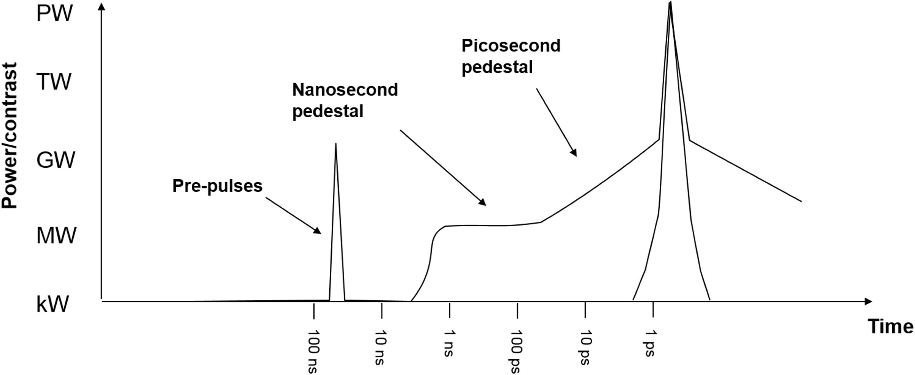
Figure 37. Illustration of sources of contrast issues.
∙ 30 W CW output from Cr:ZnSe was achieved by fibre pumping at
$1.9~\unicode[STIX]{x03BC}\text{m}$
wavelength[Reference Mirov, Fedorov, Martyshkin, Moskalev, Mirov and Vasilyev270].∙ A mode-locked oscillator generating 41 fs was reported by Tolstik et al. in 2014[Reference Tolstik, Pospischil, Sorokin and Sorokina275].
∙ The demonstration of a 1 J long pulse from Cr:ZnSe[Reference Fedorov, Mirov, Mirov, Gapontsev, Erofeev, Smirnov and Altshuler276] shows that not only average power but also high pulse energies are possible.
∙ The amplification of a 27 fs pulse with a spectral width that would even allow 16 fs[Reference Cole, Goldberg and Hays267] shows the capability for the generation of very short pulses and amplification with a gain of 500[Reference Vasilyev, Moskalev, Mirov, Smolski, Mirov and Gapontsev273].

The combination of ultra-broadband transition metal chalcogenides pumped by diode-pumped Tm-doped solid-state lasers offers a promising two-step approach for the generation of ultra-intense laser pulses in the MIR (around $2.5~\unicode[STIX]{x03BC}\text{m}$
). In contrast to the traditional Ti:sapphire lasers that are pumped by frequency-doubled Nd lasers, no additional nonlinearity is involved. Some attempts can already be found in the literature – for instance, Yumoto et al. showed an optical-to-optical efficiency of 44% for a Cr:ZnSe laser pumped by Tm:YAG[Reference Yumoto, Saito, Takagi, Tomida and Wada277] and a tuning range of this setup of at least 600 nm[Reference Yumoto, Saito, Takagi and Wada278].
$2.5~\unicode[STIX]{x03BC}\text{m}$
). In contrast to the traditional Ti:sapphire lasers that are pumped by frequency-doubled Nd lasers, no additional nonlinearity is involved. Some attempts can already be found in the literature – for instance, Yumoto et al. showed an optical-to-optical efficiency of 44% for a Cr:ZnSe laser pumped by Tm:YAG[Reference Yumoto, Saito, Takagi, Tomida and Wada277] and a tuning range of this setup of at least 600 nm[Reference Yumoto, Saito, Takagi and Wada278].
Transition-metal-doped zinc chalcogenides are not the only option for broadband amplifiers pumped by $\text{Tm}^{3+}$
-based lasers. Another route may be offered by optically pumping a
$\text{Tm}^{3+}$
-based lasers. Another route may be offered by optically pumping a $\text{CO}_{2}$
-laser. High-peak-power
$\text{CO}_{2}$
-laser. High-peak-power $\text{CO}_{2}$
-lasers that are traditionally discharge-pumped are already being developed nowadays[Reference Polyanskiy, Babzien and Pogorelsky279]. It seems that 100 TW and more are achievable in the
$\text{CO}_{2}$
-lasers that are traditionally discharge-pumped are already being developed nowadays[Reference Polyanskiy, Babzien and Pogorelsky279]. It seems that 100 TW and more are achievable in the $10~\unicode[STIX]{x03BC}\text{m}$
wavelength range. The even longer wavelength and the advantages of being gas lasers make them promising candidates for high-peak-power applications such as particle acceleration[Reference Chen, Helle, Ting, Gordon, Dover, Ettlinger, Najmudin, Polyanskiy, Pogorelsky and Babzien280, Reference Pogorelsky, Babzien, Polyanskiy and Kimura281].
$10~\unicode[STIX]{x03BC}\text{m}$
wavelength range. The even longer wavelength and the advantages of being gas lasers make them promising candidates for high-peak-power applications such as particle acceleration[Reference Chen, Helle, Ting, Gordon, Dover, Ettlinger, Najmudin, Polyanskiy, Pogorelsky and Babzien280, Reference Pogorelsky, Babzien, Polyanskiy and Kimura281].
That optical pumping of $\text{CO}_{2}$
-lasers could be rather efficient, which had already been shown for different wavelengths and pump laser systems in the 1980s[Reference Stenersen and Wang282]. Among the different wavelengths that can be generated with high-power chemical lasers in the MIR there is also an option to use the output of thulium or holmium solid-state systems. Optical pumping has the advantage that higher-pressure gases and an extended mixture of isotopologues can be applied. The latter is possible since, in contrast to discharge-pumped
$\text{CO}_{2}$
-lasers could be rather efficient, which had already been shown for different wavelengths and pump laser systems in the 1980s[Reference Stenersen and Wang282]. Among the different wavelengths that can be generated with high-power chemical lasers in the MIR there is also an option to use the output of thulium or holmium solid-state systems. Optical pumping has the advantage that higher-pressure gases and an extended mixture of isotopologues can be applied. The latter is possible since, in contrast to discharge-pumped $\text{CO}_{2}$
-lasers, molecules are not dissociating through optical pumping and the rearrangement of isotopes will therefore not lead to a degradation of the isotopologue mixture[Reference Brandner and Urey283, Reference Yeung, Okumura, Paci, Schatz, Zhang and Minton284]. Moreover, there is no need to pump any isotopologue separately. Targeting one species is sufficient in order to incorporate all of them in the laser process. This finally results in a possible large amplification bandwidth supporting some 100 fs pulses to be amplified, which makes such lasers very attractive for high-intensity applications[Reference Campbell285].
$\text{CO}_{2}$
-lasers, molecules are not dissociating through optical pumping and the rearrangement of isotopes will therefore not lead to a degradation of the isotopologue mixture[Reference Brandner and Urey283, Reference Yeung, Okumura, Paci, Schatz, Zhang and Minton284]. Moreover, there is no need to pump any isotopologue separately. Targeting one species is sufficient in order to incorporate all of them in the laser process. This finally results in a possible large amplification bandwidth supporting some 100 fs pulses to be amplified, which makes such lasers very attractive for high-intensity applications[Reference Campbell285].
4.3.2 Improvements in temporal contrast
When the first CPA high-power lasers were being built the goal was to deliver the highest focused intensity to target; temporal contrast was not a major concern. However, it became rapidly apparent that any energy delivered to the target before the main laser pulse arrived could radically change the conditions of the interactions[Reference Natel, Itatani, Tien, Faure, Kaplan, Bouvier, Buma, Van Rompay, Nees, Pronko, Umstadter and Mourou286]. The ability to deliver a ‘temporally clean’ laser pulse is now one of the key parameters of any petawatt class laser system, and becomes increasingly important as we move into new regimes at focused intensities in excess of $10^{23}~\text{W}/\text{cm}^{2}$
.
$10^{23}~\text{W}/\text{cm}^{2}$
.
The energy which can precede the main laser pulse results from six principal mechanisms (Figure 37).
∙ Amplified spontaneous emission (ASE) from conventional laser amplifiers. This lasts for the lifetime of the laser ion used in the amplifier and/or the pump duration, typically hundreds of microseconds. If a regenerative amplifier is used, pedestals of the
$Q$
-switch duration of the amplifier (typically hundreds of nanoseconds) and the amplification window (of order
${\sim}$
10 ns) are present.∙ Parametric fluorescence from optical parametric amplifiers, which lasts for the duration of the pump pulse (usually a few nanoseconds)[Reference Stuart, Bigourd, Hill, Robinson, Mecseki, Patankar, New and Smith287].
∙ The coherent pedestal due to scattering from gratings in the stretchers and compressors forms a
${\sim}$
100 ps triangular pedestal (on a logarithmic scale) on either side of the main pulse[Reference Bagnoud and Salin288].∙ Features within a few picoseconds of the pulse can be formed due to imperfect compression[Reference Tan, Forget, Borot, Kaplan, Tournois, Muschet and Veisz289].
∙ The inherent contrast of the laser (in the absence of any pulse cleaning) is limited by the quantum noise from the seed oscillator[Reference Didenko, Konyashchenko, Lutsenko and Yu291].
∙ Poorly suppressed oscillator pulses or back reflections in multi-passed components can lead to discrete pre-pulses. These may also be formed by nonlinear index effects causing post-pulses to generate pre-pulses[Reference Didenko, Konyashchenko, Lutsenko and Yu291].


The final contrast of a petawatt class laser is influenced by the design of many subsystems.
Oscillators: The innate contrast of a range of mode-locked oscillators which form the seed for all petawatt lasers has been characterized by Stuart et al. and Alessi et al. [Reference Alessi, Spinka, Betts, Kanz, Sigurdsson, Riordan, Crane and Haefner290, Reference Stuart, Robinson, Hillier, Hopps, Parry, Musgrave, Nersisyan, Sharba, Zepf and Smith292], revealing unexpected features close to the mode-locked pulses. These features can only be removed using temporally gated amplification (ps-OPA) or nonlinear processes.
Picosecond OPA: The first major improvement to the contrast of Nd:glass-based petawatt lasers was the development of self-pumped picosecond OPAs by Dorrer et al. at the University of Rochester[Reference Dorrer, Begishev, Okishev and Zuegel293]. First fielded on Vulcan by Musgrave et al.
[Reference Musgrave, Shaikh, Galimberti, Boyle, Hernandez-Gomez, Lancaster and Heathcote294] and later at OMEGA-EP[Reference Dorrer, Consentino, Irwin, Qiao and Zuegel295], Orion[Reference Hillier, Elsmere, Girling, Hopps, Hussey, Parker, Treadwell, Winter and Bett296], NIF-ARC[Reference Acree, Heebner, Prantil, Halpin, Budge, Novikova, Sigurdsson and Pelz297] and PHELIX[Reference Wagner, João, Fils, Gottschall, Hein, Körner, Limpert, Roth, Stöhlker and Bagnoud298], these systems take the output of a mode-locked oscillator and amplify it to the microjoule level in an OPA pumped with a laser seeded by another pulse from the same oscillator. By amplifying the pulse by a factor of $10^{4}$
, while it is weakly stretched, any parametric fluorescence is kept to within a few picoseconds of the pulse. Any subsequent amplifiers (such as an OPA pumped with a nanosecond duration laser) can have their gain reduced significantly and hence reduce the intensity of the parametric fluorescence in the nanosecond regime.
$10^{4}$
, while it is weakly stretched, any parametric fluorescence is kept to within a few picoseconds of the pulse. Any subsequent amplifiers (such as an OPA pumped with a nanosecond duration laser) can have their gain reduced significantly and hence reduce the intensity of the parametric fluorescence in the nanosecond regime.
Double CPA: An alternative approach which can be used in conjunction with ps-OPA is the use of double CPA[Reference Kalashnikov, Risse, Schonnagel and Sandner299]. Here the seed pulse is stretched, amplified, then compressed and passed through a nonlinear process which inhibits any structure around the main pulse. The cleaned pulse is stretched again and amplified before being compressed and focused onto target.
In systems with short ( ${<}$
100 fs) pulse durations, crossed polarized wave (XPW)[Reference Jullien, Albert, Burgy, Hamoniaux, Rousseau, Chambaret, Auge-Rochereau, Cheriaux, Etchepare, Minkovski and Saltiel300] is the most commonly used nonlinear effect. For systems with longer pulse durations low-gain OPA[Reference Shah, Johnson, Shimada, Flippo, Fernandez and Hegelich301] is more appropriate.
${<}$
100 fs) pulse durations, crossed polarized wave (XPW)[Reference Jullien, Albert, Burgy, Hamoniaux, Rousseau, Chambaret, Auge-Rochereau, Cheriaux, Etchepare, Minkovski and Saltiel300] is the most commonly used nonlinear effect. For systems with longer pulse durations low-gain OPA[Reference Shah, Johnson, Shimada, Flippo, Fernandez and Hegelich301] is more appropriate.
These processes are similar to ps-OPA in that they generate temporally clean seed pulses for the main amplification stage of a laser. However, these seed pulses still need to be stretched to nanosecond durations for further amplification, which can lead to other effects limiting the contrast.
Stretchers: On all CPA lasers a triangular pedestal exists for a few hundred picoseconds around the main pulse. This is partially due to high-frequency phase errors from the gratings, which form part of the stretchers and compressors. The impact of grating quality was studied by Dorrer et al. [Reference Dorrer and Bromage302] and later characterized and improved by Hooker et al. [Reference Bashinov, Gonoskov, Kim, Mourou and Sergeev167]. Reducing this pedestal further is still an area of active research.
Beamline design: Other features within the beamline also have an impact on the contrast. Plane parallel surfaces can generate post-pulses when the main laser pulses pass through them. In the case of OPA crystals this post-pulse will be amplified and sit, slightly delayed, under the main laser pulse. Should the stretched pulse then pass through a nonlinear process, such as saturated gain or B-integral build up along the amplifier, a pre-pulse can be generated which mirrors the post-pulse[Reference Didenko, Konyashchenko, Lutsenko and Yu291]. This effect can be avoided by using wedged OPA crystals and replacing half-wave plates with reflective polarization rotators[Reference Keppler, Hornung, Bödefeld, Kahle, Hein and Kaluza303].
In multi-passed, imaged amplifiers, ghost foci from the lenses can cause pre-pulses to be formed which lead the main pulse out of the amplifiers. This effect led to the Texas Petawatt system being redesigned by replacing the lenses in their beamline with off-axis parabolic reflectors[Reference Gaul, Toncian, Martinez, Gordon, Spinks, Dyer, Truong, Wagner, Tiwari, Donovan, Ditmire and Hegelich304].
Nonlinear processes post-compression: One of the most dependable methods of improving contrast is to cause the pulse to undergo a nonlinear process after final compression. The most common approach is the use of plasma mirrors[Reference Thaury, Quéré, Geindre, Levy, Ceccotti, Monot, Bougeard, Réau, D’Oliveira, Audebert, Majoribanks and Martin305]. Here an anti-reflection-coated blank is placed in the converging beam. When the intensity gets high enough a plasma is formed on the surface, which then reflects subsequent light with high ( ${\sim}$
70%) efficiency. Hence the mirror can be positioned such that any low-intensity pre-pulses leak through and the reflective plasma is only formed by the rising edge of the main pulse. The contrast enhancement of plasma mirrors is limited by the reflectivity of the anti-reflection coating on the blank. Further improvement to contrast can be made by using double plasma mirrors[Reference Lévy, Ceccotti, D’Oliveira, Réau, Perdrix, Quéré, Monot, Bougeard, Lagadec, Martin, Geindre and Audebert306]. By pre-ionizing the surface of the plasma mirror with a controlled pre-pulse, reflectivities of 96% have been realized[Reference Scott, Bagnoud, Brabetz, Clarke, Green, Heathcote, Powell, Zielbauer, Arber and McKenna307].
${\sim}$
70%) efficiency. Hence the mirror can be positioned such that any low-intensity pre-pulses leak through and the reflective plasma is only formed by the rising edge of the main pulse. The contrast enhancement of plasma mirrors is limited by the reflectivity of the anti-reflection coating on the blank. Further improvement to contrast can be made by using double plasma mirrors[Reference Lévy, Ceccotti, D’Oliveira, Réau, Perdrix, Quéré, Monot, Bougeard, Lagadec, Martin, Geindre and Audebert306]. By pre-ionizing the surface of the plasma mirror with a controlled pre-pulse, reflectivities of 96% have been realized[Reference Scott, Bagnoud, Brabetz, Clarke, Green, Heathcote, Powell, Zielbauer, Arber and McKenna307].
The other approach is frequency-doubling the beam post-compression. This requires very large, thin doubling crystals, to minimize nonlinear phase issues; and a series of dichroic mirrors post-compression to reject the unconverted fundamental. Conversion efficiencies of ${\sim}$
70% have been realized[Reference Hillier, Danson, Duffield, Egan, Elsmere, Girling, Harvey, Hopps, Norman, Parker, Treadwell, Winter and Bett308], but the difficulty in manufacturing large, thin crystals limits the energy that can be provided.
${\sim}$
70% have been realized[Reference Hillier, Danson, Duffield, Egan, Elsmere, Girling, Harvey, Hopps, Norman, Parker, Treadwell, Winter and Bett308], but the difficulty in manufacturing large, thin crystals limits the energy that can be provided.
Alternative schemes have been developed for short-pulse gas lasers, such as the nonlinear Fourier filter[Reference Szatmári, Dajka, Barna, Gilicze and Földes309]. Here an annular beam is formed using an apodizing mask. The beam is focused through a gas jet, re-collimated and blocked with a second mask (Figure 38). Nonlinear effects at the focus introduce an intensity-dependent directional modulation of the beam, both in time and space, causing the main pulse and the low-intensity pedestal to become spatially separated.
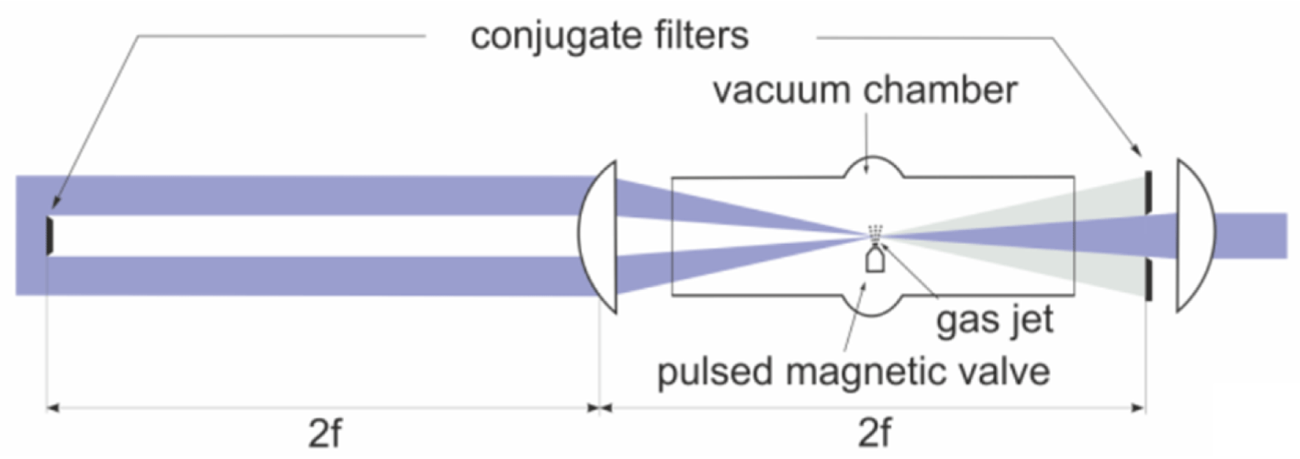
Figure 38. Schematic of the nonlinear Fourier filter.
A huge amount of work has been undertaken to provide the cleanest possible laser pulse, yet as the peak power of lasers increases so does the importance of contrast. Future facilities could rely on coherent beam combining to achieve the highest possible focused intensities, which gives the possibility of slightly mistimed beams producing interference which could throw energy from the main pulse into satellite pulses. Short pulses at large apertures are susceptible to spectral clipping in compressors, along with localized wavefront and phase errors[Reference Kalashnikov, Andreev and Schönnagel310]. The journey to 100 PW lasers will bring new problems to be solved before these systems can realize their greatest potential.
4.3.3 Plasma optics
As an optical wave propagates from vacuum into plasma it experiences a wavelength- and density-dependent refractive index which acts to refract it away from higher densities (see Equation (3)). Utilizing this effect, in combination with the optical ionization induced when a laser illuminates a solid target, it is possible to generate effective switchable plasma optic[Reference Teubner, Wagner and Forster311]. As the pulse length of high-power lasers reduced to approximately a picosecond by the mid-1990s, the plasma expansion from a solid target during the driving pulse, typically characterized by the distance over which the density reduces by $1/e$
, known as the scale length
$1/e$
, known as the scale length $L_{s}$
, also decreased. In many laser systems of this era, contrasts of
$L_{s}$
, also decreased. In many laser systems of this era, contrasts of $10^{4}$
–
$10^{4}$
– $10^{6}$
a few nanoseconds ahead of the peak of the pulse were common, and scale lengths for interactions at intensities of
$10^{6}$
a few nanoseconds ahead of the peak of the pulse were common, and scale lengths for interactions at intensities of $10^{15}$
–
$10^{15}$
– $10^{17}~\text{W}/\text{cm}^{2}$
of the order of only a few times the driving laser wavelength
$10^{17}~\text{W}/\text{cm}^{2}$
of the order of only a few times the driving laser wavelength $\unicode[STIX]{x1D706}$
became possible for the first time. For short (
$\unicode[STIX]{x1D706}$
became possible for the first time. For short ( ${<}$
ps) pulses and short scale lengths, the plasma does not typically evolve significantly hydrodynamically as the beam travels through it and the refracted output beam leaves the plasma in the specular direction. Also, the reflected fraction of the beam typically becomes more dominant over large-angle scattering at short scale lengths. Thus, novel high-quality plasma ‘reflecting’ optics which operates at high energy densities
${<}$
ps) pulses and short scale lengths, the plasma does not typically evolve significantly hydrodynamically as the beam travels through it and the refracted output beam leaves the plasma in the specular direction. Also, the reflected fraction of the beam typically becomes more dominant over large-angle scattering at short scale lengths. Thus, novel high-quality plasma ‘reflecting’ optics which operates at high energy densities ${\sim}\text{kJ}/\text{cm}^{2}$
becomes feasible.
${\sim}\text{kJ}/\text{cm}^{2}$
becomes feasible.
Initial studies in the early 1990s with nanosecond laser contrasts of ${<}10^{6}$
had shown that the reflected laser beam typically ‘broke-up’ at intensities
${<}10^{6}$
had shown that the reflected laser beam typically ‘broke-up’ at intensities ${\geqslant}10^{16}~\text{W}/\text{cm}^{2}$
due to large scale lengths[Reference Pirozhkov, Choi, Sung, Lee, Yu, Jeong, Kim, Hafz, Kim, Pae, Noh, Ko, Lee, Robinson, Foster, Hawkes, Streeter, Spindloe, McKenna, Carroll, Wahlström, Zepf, Adams, Dromey, Markey, Kar, Li, Xu, Nagatomo, Mori, Yogo, Kiriyama, Ogura, Sagisaka, Orimo, Nishiuchi, Sugiyama, Esirkepov, Okada, Kondo, Kanazawa, Nakai, Akutsu, Motomura, Tanoue, Shimomura, Ikegami, Daito, Kando, Kameshima, Bolton, Bulanov, Daido and Neely312] effectively producing ripples in the expanding plasma surface where the beam was being refracted. Experimenters in the early 1990s explored the potential for utilizing the plasma as a high-quality active optical switching mirror[Reference Kapteyn, Murnane, Szoke and Falcone313, Reference Gold314] and characterized performance[Reference Ziener, Foster, Divall, Hooker, Hutchinson, Langley and Neely315, Reference Doumy, Quere, Gobert, Perdrix, Martin, Audebert, Gauthier, Geindre and Wittmann316] in terms of the potential to deliver reflected pulses for subsequent high-contrast interactions, which became common practice by the early 2000s. Ellipsoidal plasma optics offers the advantage of delivering sub F/1 focusing[Reference Nakatsutsumi, Kon, Buffechoux, Audebert, Fuchs and Kodama317], enabling intensities[Reference Wilson, King, Gray, Carroll, Dance, Armstrong, Hawkes, Clarke, Robertson, Neely and McKenna318] approaching
${\geqslant}10^{16}~\text{W}/\text{cm}^{2}$
due to large scale lengths[Reference Pirozhkov, Choi, Sung, Lee, Yu, Jeong, Kim, Hafz, Kim, Pae, Noh, Ko, Lee, Robinson, Foster, Hawkes, Streeter, Spindloe, McKenna, Carroll, Wahlström, Zepf, Adams, Dromey, Markey, Kar, Li, Xu, Nagatomo, Mori, Yogo, Kiriyama, Ogura, Sagisaka, Orimo, Nishiuchi, Sugiyama, Esirkepov, Okada, Kondo, Kanazawa, Nakai, Akutsu, Motomura, Tanoue, Shimomura, Ikegami, Daito, Kando, Kameshima, Bolton, Bulanov, Daido and Neely312] effectively producing ripples in the expanding plasma surface where the beam was being refracted. Experimenters in the early 1990s explored the potential for utilizing the plasma as a high-quality active optical switching mirror[Reference Kapteyn, Murnane, Szoke and Falcone313, Reference Gold314] and characterized performance[Reference Ziener, Foster, Divall, Hooker, Hutchinson, Langley and Neely315, Reference Doumy, Quere, Gobert, Perdrix, Martin, Audebert, Gauthier, Geindre and Wittmann316] in terms of the potential to deliver reflected pulses for subsequent high-contrast interactions, which became common practice by the early 2000s. Ellipsoidal plasma optics offers the advantage of delivering sub F/1 focusing[Reference Nakatsutsumi, Kon, Buffechoux, Audebert, Fuchs and Kodama317], enabling intensities[Reference Wilson, King, Gray, Carroll, Dance, Armstrong, Hawkes, Clarke, Robertson, Neely and McKenna318] approaching $10^{22}~\text{W}/\text{cm}^{2}$
with current petawatt class lasers, and the prospect of enhancement of the focused intensities of future systems, illustrated in Figure 39.
$10^{22}~\text{W}/\text{cm}^{2}$
with current petawatt class lasers, and the prospect of enhancement of the focused intensities of future systems, illustrated in Figure 39.
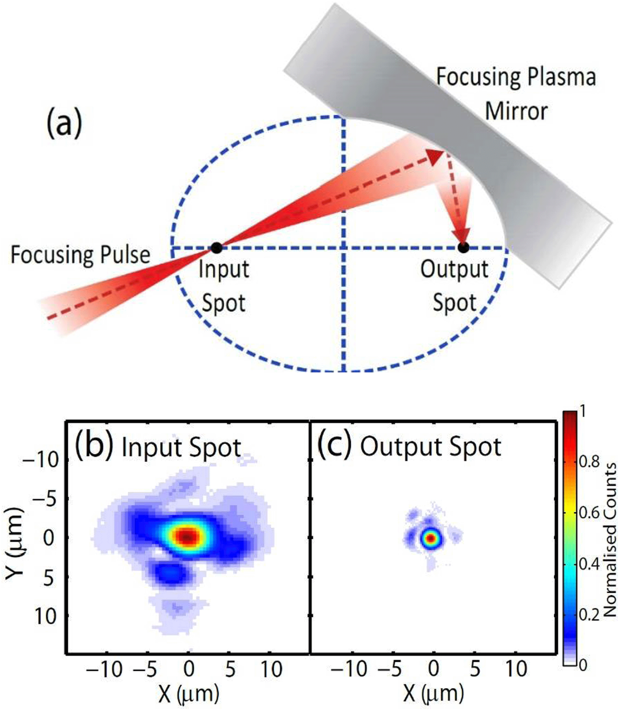
Figure 39. (a) Schematic illustrating the operation principle of an ellipsoidal focusing plasma mirror to increase the intensity by a factor of five. (b) Input laser focal spot spatial-intensity distributions using $f/3$
illumination at 1053 nm and (c) the output spot image obtained, demonstrating a demagnification of
$f/3$
illumination at 1053 nm and (c) the output spot image obtained, demonstrating a demagnification of $1/3$
in this ellipsoidal geometry[Reference Wilson, King, Gray, Carroll, Dance, Armstrong, Hawkes, Clarke, Robertson, Neely and McKenna318].
$1/3$
in this ellipsoidal geometry[Reference Wilson, King, Gray, Carroll, Dance, Armstrong, Hawkes, Clarke, Robertson, Neely and McKenna318].
Recently, it has been observed that by utilizing a suitable picosecond-scale pre-pulse on the surface of a plasma mirror, the scale length can be optimized[Reference Gordon, Stamm, Hafizi, Johnson, Kaganovich, Hubbard, Richardson and Zhigunov319] to minimize absorption and give reflectivities of 96% for the main pulse, approaching that of conventional multi-layers. The new generation of high-repetition-rate lasers will require plasma optics that can be fielded at repetition rates of ${>}$
Hz, and tapes[Reference Sokollik, Shiraishi, Osterhoff, Evans, Gonsalves, Nakamura, van Tilborg, Lin, Toth and Leemans320] or liquids are an obvious choice. Liquid plasma mirrors were first investigated in the early 1990s[Reference Backus, Kapteyn, Murnane, Gold, Nathel and White321] and high reflectivities were achieved using water[Reference Panasenko, Shu, Gonsalves, Nakamura, Matlis, Toth and Leemans322], which has minimal associated hazards. More recently, liquid crystals have been studied as their thickness can be readily tuned[Reference Poole, Krygier, Cochran, Foster, Scott, Wilson, Bailey, Bourgeois, Hernandez-Gomez, Neely, Rajeev, Freeman and Schumacher323] to
${>}$
Hz, and tapes[Reference Sokollik, Shiraishi, Osterhoff, Evans, Gonsalves, Nakamura, van Tilborg, Lin, Toth and Leemans320] or liquids are an obvious choice. Liquid plasma mirrors were first investigated in the early 1990s[Reference Backus, Kapteyn, Murnane, Gold, Nathel and White321] and high reflectivities were achieved using water[Reference Panasenko, Shu, Gonsalves, Nakamura, Matlis, Toth and Leemans322], which has minimal associated hazards. More recently, liquid crystals have been studied as their thickness can be readily tuned[Reference Poole, Krygier, Cochran, Foster, Scott, Wilson, Bailey, Bourgeois, Hernandez-Gomez, Neely, Rajeev, Freeman and Schumacher323] to ${<}$
200 nm and they can be designed to be operated at
${<}$
200 nm and they can be designed to be operated at $\gg$
Hz repetition rates. Such thin plasma mirrors will be ideal for staged acceleration[Reference Steinke, van Tilborg, Benedetti, Geddes, Schroeder, Daniels, Swanson, Gonsalves, Nakamura, Matlis, Shaw, Esarey and Leemans324] or beam combination/extraction in the near future, as high-energy photons/electrons/ions will easily pass through a thin plasma mirror without suffering significant absorption or scattering.
$\gg$
Hz repetition rates. Such thin plasma mirrors will be ideal for staged acceleration[Reference Steinke, van Tilborg, Benedetti, Geddes, Schroeder, Daniels, Swanson, Gonsalves, Nakamura, Matlis, Shaw, Esarey and Leemans324] or beam combination/extraction in the near future, as high-energy photons/electrons/ions will easily pass through a thin plasma mirror without suffering significant absorption or scattering.
At intensities of $\gg 10^{18}~\text{W}/\text{cm}^{2}$
the laser interaction can lead to two additional and significant effects on plasma mirrors[Reference Horlein, Dromey, Adams, Nomura, Kar, Markey, Foster, Neely, Krausz, Tsakiris and Zepf325]. The light pressure can steepen the density gradient close to critical and the electric field associated with the pulse can drive the plasma electrons/surface, forcing it to oscillate significantly. In such circumstances, a few percent of the incoming beam is converted into the second harmonic, being emitted in the specular reflected beam direction. This work was extended[Reference Streeter, Foster, Cameron, Borghesi, Brenner, Carroll, Divall, Dover, Dromey, Gallegos, Green, Hawkes, Hooker, Kar, McKenna, Nagel, Najmudin, Palmer, Prasad, Quinn, Rajeev, Robinson, Romagnani, Schreiber, Spindloe, Ter-Avetisyan, Tresca, Zepf and Neely326] to intensities of
$\gg 10^{18}~\text{W}/\text{cm}^{2}$
the laser interaction can lead to two additional and significant effects on plasma mirrors[Reference Horlein, Dromey, Adams, Nomura, Kar, Markey, Foster, Neely, Krausz, Tsakiris and Zepf325]. The light pressure can steepen the density gradient close to critical and the electric field associated with the pulse can drive the plasma electrons/surface, forcing it to oscillate significantly. In such circumstances, a few percent of the incoming beam is converted into the second harmonic, being emitted in the specular reflected beam direction. This work was extended[Reference Streeter, Foster, Cameron, Borghesi, Brenner, Carroll, Divall, Dover, Dromey, Gallegos, Green, Hawkes, Hooker, Kar, McKenna, Nagel, Najmudin, Palmer, Prasad, Quinn, Rajeev, Robinson, Romagnani, Schreiber, Spindloe, Ter-Avetisyan, Tresca, Zepf and Neely326] to intensities of $10^{21}~\text{W}/\text{cm}^{2}$
by 2011, with the conversion efficiency into second harmonic reaching 20%, equivalent to that achieved for BBO crystals of the time for such broad bandwidth 35 fs pulses. Due to the short optical path in the plasma, this conversion mechanism should also be suitable for much shorter driving pulses. As well as the second harmonic, higher harmonics have also been observed as the driving intensity is increased. By 1996 the 75th harmonic had been detected[Reference Zepf, Moustaizis, Fews, Zhang, Lee, Bakarezos, Danson, Dyson, Gibbon, Loukakos, Neely, Walsh, Wark, Dangor and Norreys327] and enhanced driving contrast continued to improve the conversion efficiency[Reference Ren, Duda, Hemker, Mori, Katsouleas, Antonsen and Mora328] due to the associated sharper density gradients, with the 2000th harmonic being observed[Reference Dromey, Kar, Bellei, Carroll, Clarke, Green, Kneip, Markey, Nagel, Simpson, Willingale, McKenna, Neely, Najmudin, Krushelnick, Norreys and Zepf329] by 2007.
$10^{21}~\text{W}/\text{cm}^{2}$
by 2011, with the conversion efficiency into second harmonic reaching 20%, equivalent to that achieved for BBO crystals of the time for such broad bandwidth 35 fs pulses. Due to the short optical path in the plasma, this conversion mechanism should also be suitable for much shorter driving pulses. As well as the second harmonic, higher harmonics have also been observed as the driving intensity is increased. By 1996 the 75th harmonic had been detected[Reference Zepf, Moustaizis, Fews, Zhang, Lee, Bakarezos, Danson, Dyson, Gibbon, Loukakos, Neely, Walsh, Wark, Dangor and Norreys327] and enhanced driving contrast continued to improve the conversion efficiency[Reference Ren, Duda, Hemker, Mori, Katsouleas, Antonsen and Mora328] due to the associated sharper density gradients, with the 2000th harmonic being observed[Reference Dromey, Kar, Bellei, Carroll, Clarke, Green, Kneip, Markey, Nagel, Simpson, Willingale, McKenna, Neely, Najmudin, Krushelnick, Norreys and Zepf329] by 2007.
Utilizing the nonlinear plasma response has been used to produce shorter ( ${<}$
picosecond) duration pulses at higher powers than lasers could deliver at the time. Raman scattering in the plasma was used to self-modulate the pulse intensity envelope and self-focusing employed to effectively extend the interaction length over which a pulse propagates and maintains a sufficiently high intensity[Reference Antonsen and Mora330, Reference Antonsen and Mora331]. Simple gas jets were initially employed by many in the early 1990s and have been used extensively for laser-driven electron acceleration[Reference Tajima and Dawson332, Reference Esarey, Schroeder and Leemans333] studies. However, more complex gas cells with density structures, capillary discharge devices[Reference Ehelich, Cohen, Zigler, Krall, Sprangle and Esarey334–Reference Spence, Bulter and Hooker336] and multi-pulses[Reference Durfee and Milchberg337], have been used to deliver tunable GeV-scale electron beams[Reference Kienel, Müller, Klenke, Limpert and Tünnermann230] over many centimetres of interaction length. The nonlinear plasma response can also be utilized for compressing[Reference Ren, Duda, Hemker, Mori, Katsouleas, Antonsen and Mora328] and focusing[Reference Palastro, Gordon, Hafizi, Johnson, Penano, Hubbard, Helle and Kaganovich338] short
${<}$
picosecond) duration pulses at higher powers than lasers could deliver at the time. Raman scattering in the plasma was used to self-modulate the pulse intensity envelope and self-focusing employed to effectively extend the interaction length over which a pulse propagates and maintains a sufficiently high intensity[Reference Antonsen and Mora330, Reference Antonsen and Mora331]. Simple gas jets were initially employed by many in the early 1990s and have been used extensively for laser-driven electron acceleration[Reference Tajima and Dawson332, Reference Esarey, Schroeder and Leemans333] studies. However, more complex gas cells with density structures, capillary discharge devices[Reference Ehelich, Cohen, Zigler, Krall, Sprangle and Esarey334–Reference Spence, Bulter and Hooker336] and multi-pulses[Reference Durfee and Milchberg337], have been used to deliver tunable GeV-scale electron beams[Reference Kienel, Müller, Klenke, Limpert and Tünnermann230] over many centimetres of interaction length. The nonlinear plasma response can also be utilized for compressing[Reference Ren, Duda, Hemker, Mori, Katsouleas, Antonsen and Mora328] and focusing[Reference Palastro, Gordon, Hafizi, Johnson, Penano, Hubbard, Helle and Kaganovich338] short ${\sim}$
30 fs beams, with expectations that they could readily handle multi-petawatt powers and deliver near-ideal focusing if a suitable density profile is obtained[Reference Gordon, Stamm, Hafizi, Johnson, Kaganovich, Hubbard, Richardson and Zhigunov319]. More complex phenomena such as plasma compression and diffraction[Reference Wu, Sheng, Zhang, Cang and Zhang339, Reference Suntsov, Abdollahpour, Papazoglou and Tzortzakis340] can also be used to manipulate the beam[Reference Monchoce, Kahaly, Leblanc, Videau, Combis, Reau, Garzella, D’Oliveira, Martin and Quere341]. Future plasma components will also utilize relativistic effects to deliver novel optics[Reference Mourou, Tajima and Bulanov342] with high damage thresholds[Reference Ren, Duda, Hemker, Mori, Katsouleas, Antonsen and Mora328], such as plasma apertures[Reference Gonzalez-Izquierdo, Gray, King, Dance, Wilson, McCreadie, Butler, Capdessus, Hawkes, Green, Murphy, Stockhausen, Carroll, Booth, Scott, Borghesi, Neely and McKenna343], waveplates, separators, holograms[Reference Leblanc, Denoeud, Chopineau, Mennerat, Martin and Quere344] and q-plates[Reference Qu, Jia and Fisch345], and uses in areas such as plasma amplification, discussed in Section 4.1.3, will be further developed to enable new interaction regimes to be reached.
${\sim}$
30 fs beams, with expectations that they could readily handle multi-petawatt powers and deliver near-ideal focusing if a suitable density profile is obtained[Reference Gordon, Stamm, Hafizi, Johnson, Kaganovich, Hubbard, Richardson and Zhigunov319]. More complex phenomena such as plasma compression and diffraction[Reference Wu, Sheng, Zhang, Cang and Zhang339, Reference Suntsov, Abdollahpour, Papazoglou and Tzortzakis340] can also be used to manipulate the beam[Reference Monchoce, Kahaly, Leblanc, Videau, Combis, Reau, Garzella, D’Oliveira, Martin and Quere341]. Future plasma components will also utilize relativistic effects to deliver novel optics[Reference Mourou, Tajima and Bulanov342] with high damage thresholds[Reference Ren, Duda, Hemker, Mori, Katsouleas, Antonsen and Mora328], such as plasma apertures[Reference Gonzalez-Izquierdo, Gray, King, Dance, Wilson, McCreadie, Butler, Capdessus, Hawkes, Green, Murphy, Stockhausen, Carroll, Booth, Scott, Borghesi, Neely and McKenna343], waveplates, separators, holograms[Reference Leblanc, Denoeud, Chopineau, Mennerat, Martin and Quere344] and q-plates[Reference Qu, Jia and Fisch345], and uses in areas such as plasma amplification, discussed in Section 4.1.3, will be further developed to enable new interaction regimes to be reached.
4.3.4 Grand technological challenges
As petawatt/exawatt laser systems are developed in the future there are a number of grand challenges facing the community to realize their potential. In this section we have briefly examined four areas which need to be addressed:
∙ Advanced optics
∙ Laser diagnostics
∙ Plasma diagnostics
∙ Target fabrication.
4.3.4.1 Advanced optics
The performance limits of optical components are of crucial importance in realizing the potential of petawatt systems. The principal limitation dictating the energy and power available on target is usually laser-induced damage of the compressor gratings, where energetic short pulses are first exhibited in a beamline[Reference Bonod and Neauport346]. To realize the highest intensity, one requires gratings with aperture ${>}$
1 m, high-efficiency diffraction over bandwidths of hundreds of nanometres and minimal diffracted wavefront errors. For designs using high-angle-of-incidence gratings, the limit may be transferred to the post-compression optics, such as the focusing mirror.
${>}$
1 m, high-efficiency diffraction over bandwidths of hundreds of nanometres and minimal diffracted wavefront errors. For designs using high-angle-of-incidence gratings, the limit may be transferred to the post-compression optics, such as the focusing mirror.
The effective grating aperture may be increased by tiling multiple gratings (and/or other transport optics)[Reference Zhang, Yonemura and Kato347]. In this scheme, the gratings must be positioned with interferometric accuracy in five degrees of freedom (only translation parallel to the grooves has a relaxed tolerance). Such a scheme is an inherent feature of the coherent recombination of sub-apertures discussed elsewhere. It has been shown in the case of NIF-ARC, for example, that even when the dispersion in sub-apertures differs slightly, then the overall dephasing between beams in the spectral/temporal regime can be controlled[Reference Homoelle, Crane, Shverdin, Haefner and Siders348].
Controlling the wavefront through the compressor is important to minimize spatiotemporal coupling and realize the highest intensities. Adaptive optics systems both before and after compression can address this issue.
When operating with high repetition frequencies and high average power, the thermal loading on the optics and opto-mechanics becomes significant. For example, control of the zero-order beam from gratings is necessary to avoid local heating of components. Absorption within optical components must also be minimized. High-repetition-rate systems also require laser gain media suitable for diode pumping. Materials with a broader gain bandwidth, such as Nd:glass, may be used for direct CPA lasers, or for pumping Ti:sapphire or OPCPA systems. Narrowband systems may only be used as pump sources.
Future OPCPA systems with very high energy will require developments in gain media. For example, highly deuterated ( ${\sim}$
90%) DKDP crystals, cut for Type-I phase-matching, with high optical quality over a large aperture are required[Reference Voronin, Zheltikov, Ditmire, Rus and Korn173, Reference Liang, Xie, Zhang, Kang, Yang, Zhu, Guo, Zhu, Yang, Cui, Sun and Zhu349]. Coating development is also necessary to achieve high damage thresholds with very large bandwidths and adequate control of spectral phase[Reference Razskazovskaya, Krausz and Pervak350].
${\sim}$
90%) DKDP crystals, cut for Type-I phase-matching, with high optical quality over a large aperture are required[Reference Voronin, Zheltikov, Ditmire, Rus and Korn173, Reference Liang, Xie, Zhang, Kang, Yang, Zhu, Guo, Zhu, Yang, Cui, Sun and Zhu349]. Coating development is also necessary to achieve high damage thresholds with very large bandwidths and adequate control of spectral phase[Reference Razskazovskaya, Krausz and Pervak350].
Improvements in optics performance are expected to plateau unless advances in optical metamaterials[Reference Shalaev351] become relevant. Further progress in ultra-high intensity may depend upon alternative schemes, such as the Compression after Compressor Approach (CafCA) and plasma amplifiers, both discussed elsewhere in this paper.
4.3.4.2 Laser diagnostics
While high-power lasers can generate extreme conditions of matter, for the physics to be understood the laser must be well characterized and diagnosed at the point that hits the target. The key parameters required for each experiment differ, but consistency and control of the delivery of energy is essential to reproducible science. With the increase in peak and average power of new laser systems, new challenges have come to the fore.
The traditional method of diagnosing a laser is subsampling a beam through a pick off or leak through an optic before reducing it down and sending it to a suite of diagnostics. This becomes increasingly difficult as broad bandwidths and high intensities become the norm. The impact of nonlinear effects on material dispersion means that the diagnostic beam can be radically different from the main beam[Reference Musgrave, Galimberti, Boyle, Hernandez-Gomez, Kidd, Parry, Pepler, Winstone and Collier352]. While these effects can be compensated for, the further one goes from measuring the original beam, the more vulnerable to variation in beam properties the diagnostics becomes.
All of the exawatt class facilities currently proposed rely on combining many beams at target to reach the highest intensities. In order to ensure full coherent combination, the full spatiotemporal information of the beams must be measured, including intensity and phase in time and space domains. Advanced diagnostics are therefore required to reconstruct the E-field, such as STRIPED FISH[Reference Zhu, Jafari, Jones and Trebino353] (Spatially and Temporally Resolved Intensity and Phase Evaluation Device: Full Information from a Single Hologram) shown in Figure 40 or TERMITES[Reference Pariente, Gallet, Borot, Gobert and Quéré354] (Total E-Field Reconstruction using a Michelson Interferometer Temporal Scan).
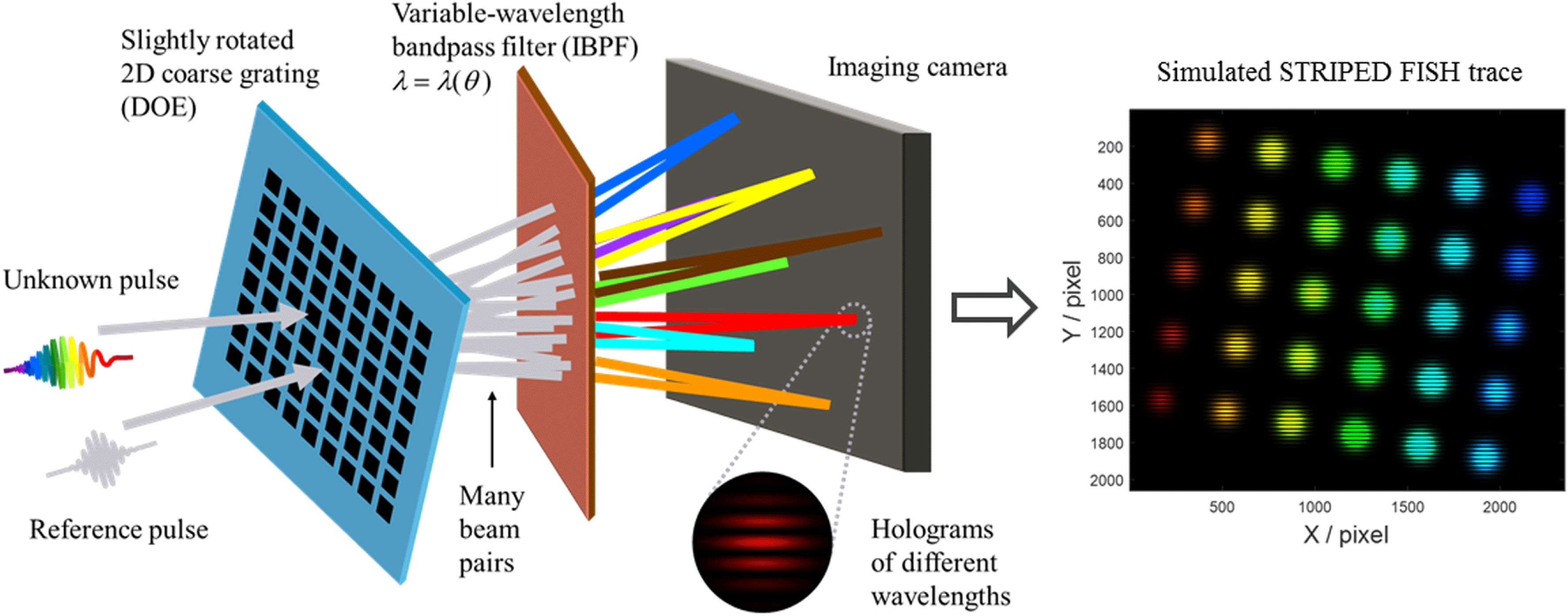
Figure 40. The schematic of a STRIPED FISH apparatus for single-shot complete spatiotemporal pulse measurement (reproduced from Ref. [Reference Zhu, Jafari, Jones and Trebino353]).
With increased repetition rates the rate at which diagnostic data is produced increases dramatically. Analysis and optimization of the system can be performed in real time and automated[Reference Telford, Bayramian, Charron, Fallejo, Fulkerson, Johnson, Kim, Koh, Lanning, Marshall, Nissen, Petersen, Spinka, Haefner, Drouin, Kasl, Mazanec, Naylon and Rus355] to provide more robust facilities. These techniques can even be applied to the plasma diagnostics themselves, dynamically changing the laser parameters to optimize experimental conditions[Reference Streeter, Dann, Scott, Baird, Murphy, Eardley, Smith, Rozario, Gruse, Mangles, Najmudin, Tata, Krishnamurthy, Rahul, Hazra, Pourmoussavi, Hah, Bourgeois, Thornton, Gregory, Hooker, Chekhlov, Hawkes, Parry, Marshall, Tang, Springate, Rajeev, Thomas and Symes356].
At the other extreme for single-shot facilities the demand for increased information about the pulse as delivered at focus increases. Techniques that had previously been used in a scanning operation, such as high-dynamic-range contrast measurements, now need to be converted to single shot[Reference Tabak, Hammer, Glinsky, Kruer, Wilks, Woodworth, Campbell and Perry141].
All of the aforementioned diagnostics use small optics and are sensitive to wavefront (including pointing) and some require small time-bandwidth products. On large aperture laser systems those are often a challenge. Furthermore, beam sampling and the beam transport to the diagnostics station are challenging due to B-integral and other nonlinear effects.
Finally, most high intensity laser applications require highest intensities but the community still lacks an online diagnostic that measures intensity directly. None of these challenges are insurmountable, but new techniques will need to be developed and matured to a point that they can leave the lab and become reliable facility diagnostics.
4.3.4.3 Plasma diagnostics
Measuring the radiation, particles, physical states and energy flows present within the broad range of plasmas generated during the interaction of a petawatt class laser with matter[Reference Roth357] is an ongoing and critical challenge for the future of the field. If the community is to effectively deliver the envisaged wide range of medical[Reference Albert, Thomas, Mangles, Banerjee, Corde, Flacco, Litos, Neely, Vieira, Najmudin, Bingham, Joshi and Katsouleas358], scientific[Reference Riley359] and industrial[Reference Brenner, Mirfayzi, Rusby, Armstrong, Alejo, Wilson, Clarke, Ahmed, Butler, Haddock, Higginson, McClymont, Murphy, Notley, Oliver, Allott, Hernandez-Gomez, Kar, McKenna and Neely360] investigations and applications accessible with new high-power, high-repetition-rate lasers, a number of specialized diagnostics will be needed. They must be capable of characterizing not only the primary plasma but also any secondary beams[Reference Bolton, Borghesi, Brenner, Carroll, De Martinis, Flacco, Floquet, Fuchs, Gallegos, Giove, Green, Green, Jones, Kirby, McKenna, Neely, Nuesslin, Prasad, Reinhardt, Roth, Schramm, Scott, Ter-Avetisyan, Tolley, Turchetti and Wilkens361] and their subsequent interactions. High-dynamic-range systems (12–18 bit) capable of differentiating and detecting structures, materials and features will be required from the sub-micron scale through to characterizing large ${\sim}10~\text{m}^{2}$
areas for industrial and medical imaging[Reference Lewis362]. Combining high-resolution sensing and multi-modal capability, utilizing the broad range of particles and radiation (X-rays[Reference Norreys, Santala, Clarke, Zepf, Watts, Beg, Krushelnick, Tatarakis, Dangor, Fang, Graham, McCanny, Singhal, Ledingham, Creswell, Sanderson, Magill, Machacek, Wark, Allott, Kennedy and Neely363], THz, ions[Reference Daido, Nishiuchi and Pirozhkov364], electrons[Reference Downer365], muons, neutrons etc.) available from laser-driven sources will deliver new capability to the community. Efforts on meeting these and similar challenges are underway internationally, not only within the laser plasma community but also at other facilities such as XFELs, Tokamaks, synchrotrons and accelerators, as they face similar challenges in diagnostics, analysis and data management.
${\sim}10~\text{m}^{2}$
areas for industrial and medical imaging[Reference Lewis362]. Combining high-resolution sensing and multi-modal capability, utilizing the broad range of particles and radiation (X-rays[Reference Norreys, Santala, Clarke, Zepf, Watts, Beg, Krushelnick, Tatarakis, Dangor, Fang, Graham, McCanny, Singhal, Ledingham, Creswell, Sanderson, Magill, Machacek, Wark, Allott, Kennedy and Neely363], THz, ions[Reference Daido, Nishiuchi and Pirozhkov364], electrons[Reference Downer365], muons, neutrons etc.) available from laser-driven sources will deliver new capability to the community. Efforts on meeting these and similar challenges are underway internationally, not only within the laser plasma community but also at other facilities such as XFELs, Tokamaks, synchrotrons and accelerators, as they face similar challenges in diagnostics, analysis and data management.
The target chamber and environment surrounding a high-intensity interaction[Reference Turcu, Negoita, Jaroszynski, Mckenna, Balascuta, Ursescu, Dancus, Cernaianu, Tataru, Ghenuche, Stutman, Boianu, Risca, Toma, Petcu, Acbas, Yoffe, Noble, Ersfeld, Brunetti, Capdessus, Murphy, Ridgers, Neely, Mangles, Gray, Thomas, Kirk, Ilderton, Marklund, Gordon, Hafizi, Kaganovich, Palastro, D’Humieres, Zepf, Sarri, Gies, Karbstein, Schreiber, Paulus, Dromey, Harvey, Di Piazza, Keitel, Kaluza, Gales and Zamfir366] can often be challenging for diagnostic operations, due to the production and escape of:
(1) large fluxes of energetic particles (primarily electrons[Reference Gunther, Sonnabend, Brambrink, Vogt, Bagnoud, Harres and Roth367], ions[Reference Borghesi, Bigongiari, Kar, Macchi, Romagnani, Audebert, Fuchs, Toncian, Willi, Bulanov, Mackinnon and Gauthier368] and neutrons);
(2) the generation of associated electromagnetic pulses (EMP)[Reference Mead, Neely, Gauoin, Heathcote and Patel369];
(3) the emission of broadband radiation at up to multi-GW power levels from THz[Reference Liao, Liu, Scott, Zhang, Zhu, Armstrong, Zemaityte, Bradford, Zhang, Li, Neely, Huggard, McKenna, Brenner, Woolsey, Wang, Sheng and Zhang370] through to hard X-rays[Reference Rusby, Armstrong, Brenner, Clarke, McKenna and Neely371];
(4) target debris.
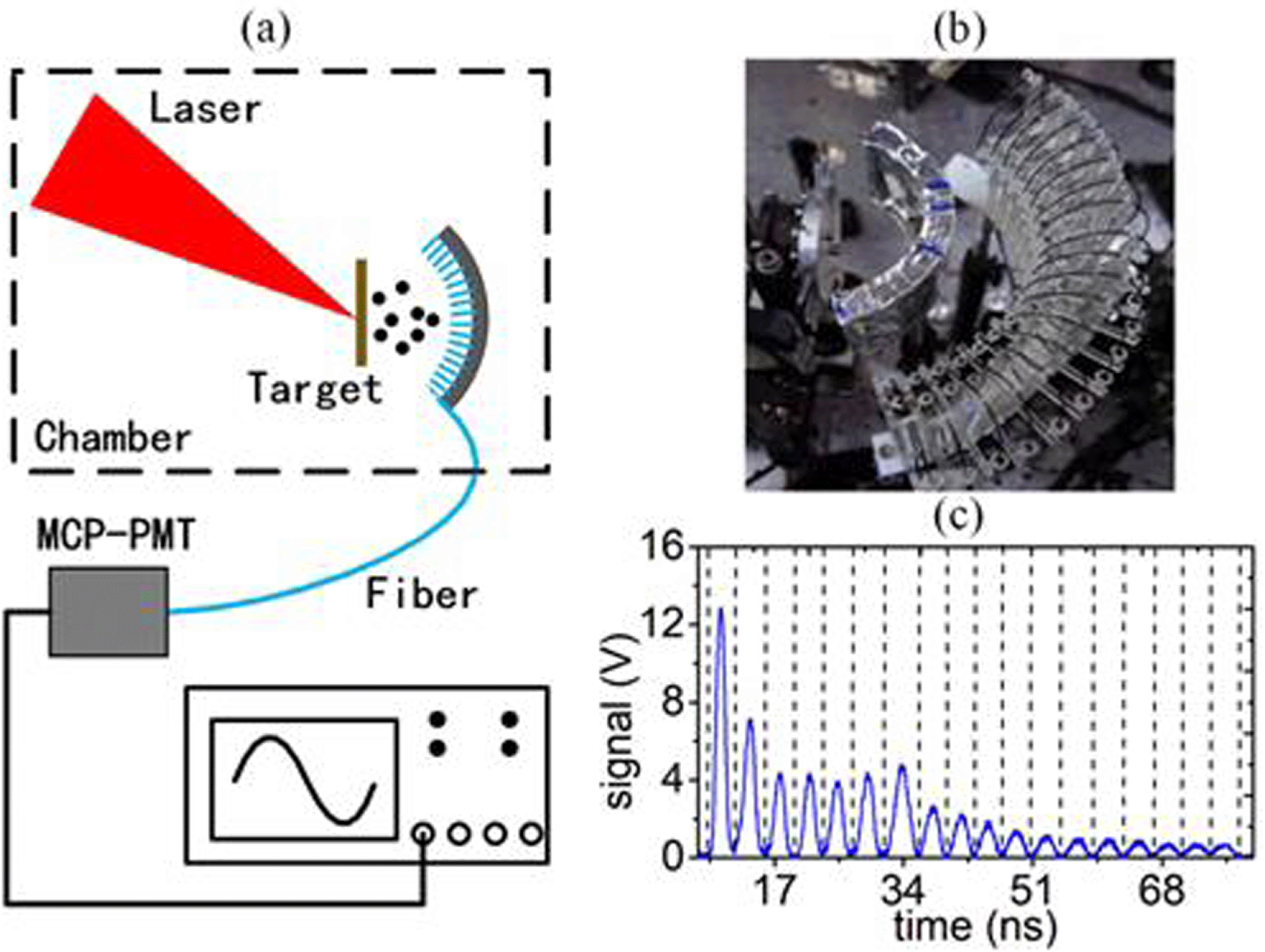
Figure 41. (a) Schematic diagram depicting an angular-resolving escaping electron diagnostic which is based on injecting Cherenkov light[Reference Liu, Liao, Zhang, Zhu, Zhang, Li, Scott, Rusby, Armstrong, Zemaityte, Carroll, Astbury, Bradford, Woolsey, McKenna and Neely380] into an optical fibre array surrounding the interaction, as shown in (b). The diagnostic is capable of operating at repetition rates of MHz and, by encoding the electron flux into an optical signal within a fibre, it can be readily transported away from the interaction area, enabling the sensitive detector and digitizing electronics to be located far from the interaction and within an EMP-shielded enclosure giving high-quality data in (c).
By designing and controlling the interaction geometry to reduce[Reference Bradford, Woolsey, Scott, Liao, Liu, Zhang, Zhu, Armstrong, Astbury, Brenner, Brummitt, Consoli, East, Gray, Haddock, Huggard, Jones, Montgomery, Musgrave, Oliveira, Rusby, Spindloe, Summers, Zemaityte, Zhang, Li, McKenna and Neely372] and mitigate[Reference Dubois, Raczka, Hulin, Rosinski, Ryc, Parys, Zaras-Szydlowska, Makaruk, Tchorz, Badziak, Wolowski, Ribolzi and Tikhonchuk373] EMP generation, many general techniques[Reference Huddlestone and Leonard374] appropriate for ‘single-shot’ operation[Reference Hutchinson375] can be delivered at high repetition rates ( $\gg$
10 Hz) with suitable retuning/redesign and the replacement of the detector element or by transporting the signal to a more benign environment[Reference Green, Borghesi, Brenner, Carroll, Dover, Foster, Gallegos, Green, Kirby, Kirkby, McKenna, Merchhant, Najmudin, Palmer, Parker, Prasad, Quinn, Rajeev, Read, Romagnani, Schreiber, Streeter, Tresca, Wahlstrom, Zepf and Neely376] before digitization (see Figure 41). Scintillators, phosphors and transducers capable of kHz–GHz rates can be readily coupled to gated or rep-rated high-dynamic-range detectors. Significant efforts are currently underway to increase radiation damage tolerance and component lifetimes when exposed to particles or ionizing fluxes and improve performance in terms of sensitivity, specificity and spatial resolution[Reference Manuel, Strehlow, Green, Parker, Alfonso, Jaquez, Carlson, Neely, Beg and Ma377]. Nuclear activation techniques utilizing isotopes with
$\gg$
10 Hz) with suitable retuning/redesign and the replacement of the detector element or by transporting the signal to a more benign environment[Reference Green, Borghesi, Brenner, Carroll, Dover, Foster, Gallegos, Green, Kirby, Kirkby, McKenna, Merchhant, Najmudin, Palmer, Parker, Prasad, Quinn, Rajeev, Read, Romagnani, Schreiber, Streeter, Tresca, Wahlstrom, Zepf and Neely376] before digitization (see Figure 41). Scintillators, phosphors and transducers capable of kHz–GHz rates can be readily coupled to gated or rep-rated high-dynamic-range detectors. Significant efforts are currently underway to increase radiation damage tolerance and component lifetimes when exposed to particles or ionizing fluxes and improve performance in terms of sensitivity, specificity and spatial resolution[Reference Manuel, Strehlow, Green, Parker, Alfonso, Jaquez, Carlson, Neely, Beg and Ma377]. Nuclear activation techniques utilizing isotopes with ${>}$
10 min half-lives have been frequently used[Reference Gamucci, Bourgeois, Ceccotti, Dobosz, D’Oliveira, Galimberti, Galy, Giulietti, Giulietti and Gizzi378] to characterize high-energy photons and particles (typically
${>}$
10 min half-lives have been frequently used[Reference Gamucci, Bourgeois, Ceccotti, Dobosz, D’Oliveira, Galimberti, Galy, Giulietti, Giulietti and Gizzi378] to characterize high-energy photons and particles (typically ${>}$
4 MeV) in the laser-plasma community. At tens of Hz such transitions would become closer to becoming integrating detectors. However, there are much shorter[Reference Clarke, Ledingham, McKenna, Robson, McCanny, Neely, Lundh, Lindau, Wahlstrom, Simpson and Zepf379] nuclear transitions which can be adopted so that individual shot measurements are possible for high-repetition-rate systems.
${>}$
4 MeV) in the laser-plasma community. At tens of Hz such transitions would become closer to becoming integrating detectors. However, there are much shorter[Reference Clarke, Ledingham, McKenna, Robson, McCanny, Neely, Lundh, Lindau, Wahlstrom, Simpson and Zepf379] nuclear transitions which can be adopted so that individual shot measurements are possible for high-repetition-rate systems.
A significant challenge facing the laser-plasma community is to deliver new, matched detectors capable of taking advantage of the short-pulse nature of laser-driven secondary sources to obtain higher-quality, higher-resolution measurements for both scientific studies and applications. This will be an area where development and new approaches and techniques are needed (for instance, efficient hard X-ray detectors with few-ps resolution would enhance backscatter imaging[Reference Deas, Wilson, Rusby, Alejo, Allott, Black, Black, Borghesi, Brenner, Bryant, Clarke, Collier, Edwards, Foster, Greenhalgh, Hernandez-Gomez, Kar, Lockley, Moss, Najmudin, Pattathil, Symes, Whittle, Wood, McKenna and Neely381] and provide discrimination against non-ballistic photons for applications such as penetrative imaging). Electronics with sufficient bandwidth to directly digitize signals with temporal resolutions of ${<}$
20 ps and streak cameras with
${<}$
20 ps and streak cameras with ${\sim}$
ps resolutions are currently available, and faster responses are envisaged in the future. Acquiring and transferring multi-megapixel, high-dynamic-range images at
${\sim}$
ps resolutions are currently available, and faster responses are envisaged in the future. Acquiring and transferring multi-megapixel, high-dynamic-range images at $\gg$
10 Hz is becoming routine for scientific-grade digital cameras. Converting, transforming or encoding the desired diagnostic information into an electrical or photonic signal[Reference Karsch, Debus, Bussmann, Schramm, Sauerbrey, Murphy, Major, Hoerlein, Veisz, Schmid, Schreiber, Witte, Jamison, Gallacher, Jaroszynski, Kaluza, Hidding, Kiselev, Heathcote, Foster, Neely, Divall, Hooker, Smith, Ertel, Langley, Norreys, Collier and Karsch382] is already a regularly used technique. However, further developments in this area will enable faster and more complex measurements to be made. Many early studies relied on only a few data points/shots, but new laser systems will offer the possibility of taking significant numbers of repeat shots per configuration, allowing weaker signals to be extracted and statistical techniques to be more fully employed. New paradigms of data acquisition utilizing the high repetition rates of future systems, more in common with particle physics, where ‘near instantaneous’ processing enables significant data reduction and selection to be undertaken, will be necessary for studies involving low-probability events.
$\gg$
10 Hz is becoming routine for scientific-grade digital cameras. Converting, transforming or encoding the desired diagnostic information into an electrical or photonic signal[Reference Karsch, Debus, Bussmann, Schramm, Sauerbrey, Murphy, Major, Hoerlein, Veisz, Schmid, Schreiber, Witte, Jamison, Gallacher, Jaroszynski, Kaluza, Hidding, Kiselev, Heathcote, Foster, Neely, Divall, Hooker, Smith, Ertel, Langley, Norreys, Collier and Karsch382] is already a regularly used technique. However, further developments in this area will enable faster and more complex measurements to be made. Many early studies relied on only a few data points/shots, but new laser systems will offer the possibility of taking significant numbers of repeat shots per configuration, allowing weaker signals to be extracted and statistical techniques to be more fully employed. New paradigms of data acquisition utilizing the high repetition rates of future systems, more in common with particle physics, where ‘near instantaneous’ processing enables significant data reduction and selection to be undertaken, will be necessary for studies involving low-probability events.
State-of-the-art hardware and infrastructure are allowing facilities to take advantage of the many new advances within the electronics/telecommunications industries, where data transfer rates of multi-GHz are now commonly available. Combining such high data flow rates with the broad range of opportunities for encoding and accessing plasma parameters will enable the next generation of laser facilities to greatly extend our diagnostic capabilities, resolutions and understanding of laser-driven interactions. Advanced high-repetition-rate diagnostics and techniques will not only enable new scientific measurements and discoveries to be made, but as laser-driven sources mature, facilities will be able to improve the quality, stability and level of control possible within the plasma and secondary source environment, enabling novel and more advanced studies and applications to be undertaken for the first time.
4.3.4.4 Target fabrication
Future target fabrication challenges can be broadly split into two main areas:
(1) targets for high-repetition-rate ultra-high-power laser systems;
(2) complex targets for multi-beam high-energy facilities, usually coupled to petawatt class beam capability.
Each of these areas has challenges to overcome to deliver the highly complex targets that are required by the respective user communities.
The commissioning of new high-repetition-rate facilities such as the ELI pillars will require a significant and fundamental change in the way targets are delivered, due to the large numbers needed to field experiments. With petawatt lasers at shot rates that are of the order of 10 Hz for ELI-BL[Reference Rus, Bakule, Kramer, Korn, Green, Novák, Fibrich, Batysta, Thoma, Naylon, Mazanec, Vítek, Barros, Koutris, Hřebíček, Polan, Baše, Homer, Košelja, Havlíček, Honsa, Novák, Zervos, Korouš, Laub and Houžvička383], and with a petawatt system at ELI-ALPS running at 10 Hz and a terawatt system running at 100 Hz[Reference Kühn, Dumergue, Kahaly, Mondal, Füle, Csizmadia, Farkas, Major, Várallyay, Cormier, Kalashnikov, Calegari, Devetta, Frassetto, Månsson, Poletto, Stagira, Vozzi, Nisoli, Rudawski, Maclot, Campi, Wikmark, Arnold, Heyl, Johnsson, L’Huillier, Lopez-Martens, Haessler, Bocoum, Boehle, Vernier, Iaquaniello, Skantzakis, Papadakis, Kalpouzos, Tzallas, Lépine, Charalambidis, Varjú, Osvay and Sansone384], there is at least two orders of magnitude increase in the number of targets that can be shot; currently there is insufficient capacity to manufacture enough targets using conventional techniques. To overcome this challenge, high-repetition-rate liquid targets have been proposed[Reference Korn, Thoss, Stiel, Vogt, Richardson, Elsaesser and Faubel385–Reference George, Morrison, Feister, Ngirmang, Smith, Klim, Snyder, Austin, Erbsen, Frische, Nees, Orban, Chowdhury and Roquemore387], and recently there has been a demonstration of multi-MeV proton acceleration from sub-micron liquid sheet targets at 1 kHz repetition rates[Reference Morrison, Feister, Frische, Austin, Ngirmang, Murphy, Orban, Chowdhury and Roquemore388].
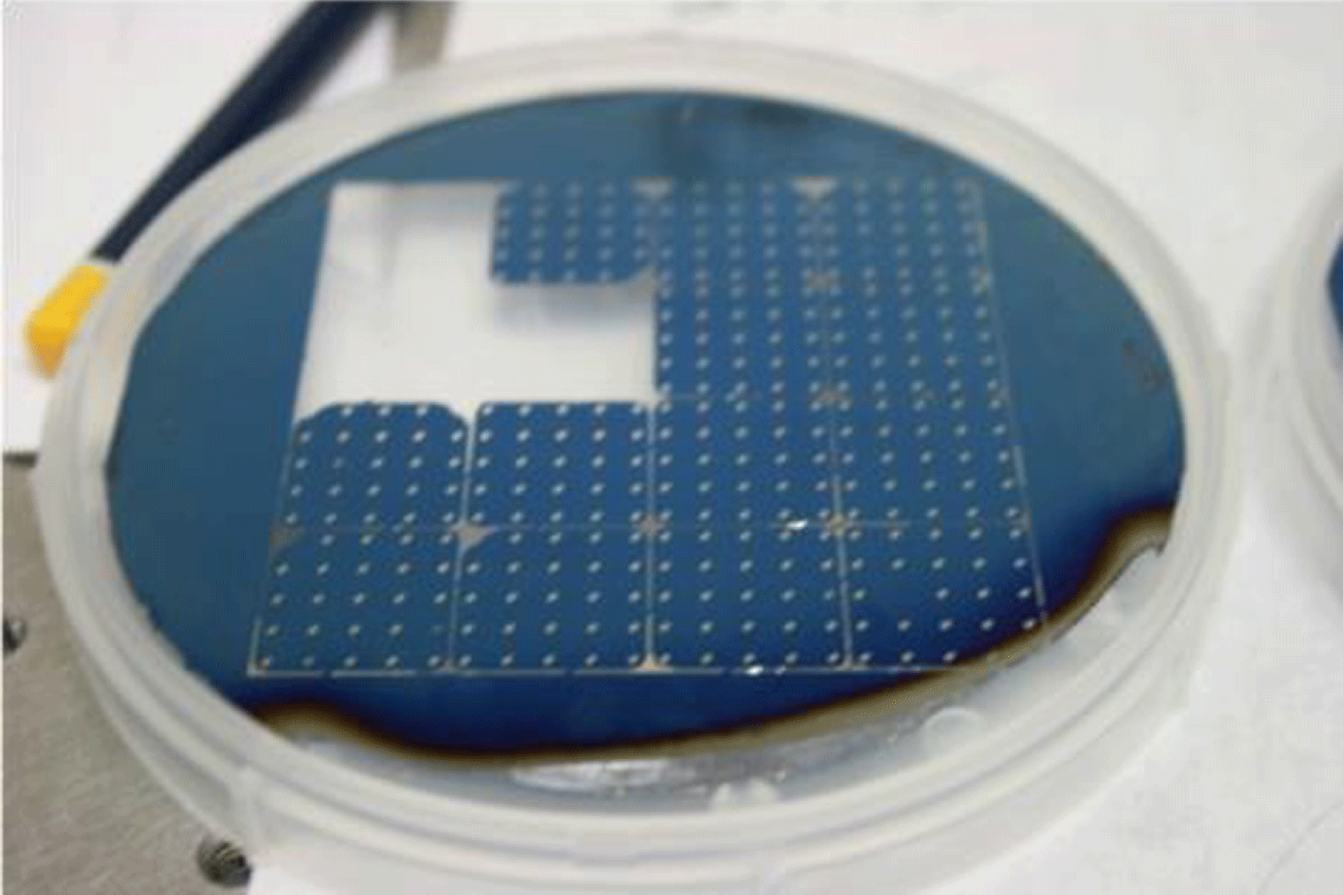
Figure 42. A 100 mm silicon wafer that has been coated with 100 nm low-stress silicon nitride and then processed using optical lithography and silicon etching to produce target arrays for the Gemini laser at RAL. Target flatness characterized to ${<}2~\unicode[STIX]{x03BC}\text{m}$
variation over the open apertures. 16 arrays produce 400 targets per wafer (picture courtesy of STFC Rutherford Appleton Laboratory).
${<}2~\unicode[STIX]{x03BC}\text{m}$
variation over the open apertures. 16 arrays produce 400 targets per wafer (picture courtesy of STFC Rutherford Appleton Laboratory).
The requirements for these and other high-power laser systems, such as the European XFEL, Gemini (UK), CLPU (Spain), Apollon (France), are well defined in a recent review of target fabrication needs[Reference Prencipe, Fuchs, Pascarelli, Schumacher, Stephens, Alexander, Briggs, Buscher, Cernaianu, Choukourov, De Marco, Erbe, Fassbender, Fiquet, Fitzsimmons, Gheorghiu, Hund, Huang, Harmand, Hartley, Irman, Kluge, Konopkova, Kraft, Kraus, Leca, Margarone, Metzkes, Nagai, Nazarov, Lutoslawski, Papp, Passoni, Pelka, Perin, Schulz, Smid, Spindloe, Steinke, Torchio, Vass, Wiste, Zaffino, Zeil, Tschentscher, Schramm and Cowan389] which highlights a range of techniques that are needed to be developed to deliver to such facilities. While some of these facilities are developing a limited range of the capabilities that are required for target manufacture, to deliver a full experimental programme, a suite of integrated technologies is needed. Coordination between each stage of what could be a complex target manufacture process, including their support, base layer coating, and etching is key (Figure 42). Target mounting also needs to be carried out in a streamlined way. This will require experts in many areas of fabrication to work with the user communities and the facilities to develop strategies to reach the most demanding of repetition rates.
In addition to a range of high-repetition-rate laser systems there are many multi-beam high-energy facilities that are open to the academic community to carry out fundamental science experiments. The National Ignition Facility (NIF) has a discovery science program with 41 shots dedicated to this in 2018[390]. These targets are provided by the extensive capabilities that are available to the NIF for its internal program in inertial confinement fusion, high-energy-density physics and national security applications. Other large-scale facilities such as the Laser MegaJoule (France), Orion (UK) and SG-III (China), while having significant internal capability, require external academic users to provide their own targets (Figure 43). These targets will require access and expertise to the most cutting-edge fabrication and assembly processes, such as diamond point turning, coatings of materials, such as high-density carbon, characterization of properties, such as grain size and orientation, and indeed the ability to change these parameters for experimental needs. These facilities are not available to most small-scale university user groups, and while larger groups such as those at the University of Michigan (US) or the Laboratory for Laser Energetics in Rochester (US) have capability to field experiments, for smaller groups national laboratories such as the Rutherford Appleton Laboratory, or commercial companies such as General Atomics or Scitech Precision, are able to provide targets.
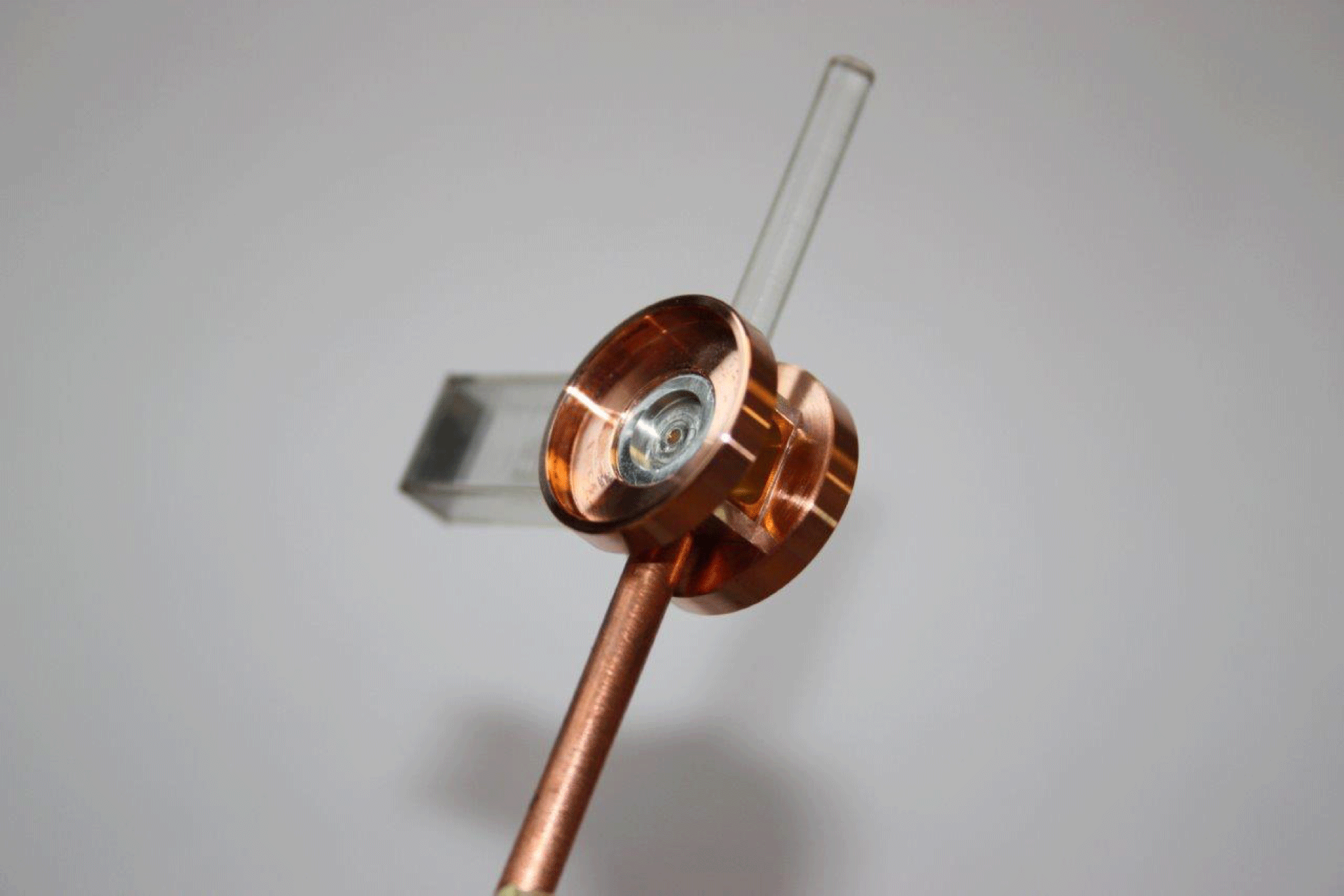
Figure 43. A complex gas target, manufactured by Scitech Precision, UK, for studying counterpropagating radiative shock collisions with X-ray radiography, generated from a petawatt laser beam, as a primary diagnostic used on experiments on SG-II at SIOM, China (picture courtesy of Imperial College London).
5 Conclusion
This review of petawatt and exawatt class lasers has attempted to provide a snapshot in time of the state-of-the-art of the global capabilities in the ultra-high-power environment. The profusion of these facilities in national laboratories and university departments is largely due to some key developments – not least, the invention of the technique of CPA. Part of the motivation for this review is to provide a tribute to the work of Donna Strickland and Gerard Mourou as the inventors of CPA and to whom the 2018 Nobel Prize in Physics was awarded.
We have presented a comprehensive overview of the current status of petawatt class lasers worldwide. We have described over 50 facilities that are, or have been, operational, under construction, or in the planning/conceptual phase. Many of these facilities are coupled and synchronized to other sources, such as nanosecond lasers, XFELs, particle beams and z-pinches.
The evolution of such facilities, and the science they have enabled, has been placed in a historical context, describing how the early pioneering work in the US has today been progressed, notably in Europe and Asia. Increasingly, as technology advances, high-average-power machines are being constructed in preference to single-shot facilities. Meanwhile, work continues apace to increase peak powers to the highest possible values.
In looking to the future, we have described some of the technologies that will lead to the next generation of lasers: delivering higher peak powers for fundamental research; and higher average powers relevant to applications. In looking through our crystal ball it is not clear what these facilities will look like 10, 20 or even 50 years from now, but it promises to be a fascinating journey.
Acknowledgements
The authors would like to acknowledge the help and advice from the following researchers in putting this review together; they provided invaluable information on specific facilities and helped validate the information presented: Nathalie Blanchot, CEA, France; Mirela Cerchez, Heinrich-Heine University, Germany; Ioan Dancus, ELI-NP, Romania; Brendan Dromey, Queen’s University Belfast, UK; Gilliss Dyer, SLAC, US; Goncalo Figueira, IST, Portugal; Alessandro Flacco, LOA, France; Julien Fuchs, Ecole Polytechnique, France; Yuqiu Gu, Research Center for Laser Fusion, China; Stefan Karsch, CALA, Germany; Junji Kawanaka, ILE Osaka University, Japan; Hiromitsu Kiriyama, KPSI, QST, Japan; Seong Ku Lee, APRI, GIST, South Korea; Aurelian Marco, CETAL, Romania; Robin Marjoribanks, University of Toronto, Canada; Mikael Martinez, SLAC, US; Paul Mason, STFC Rutherford Appleton Laboratory, UK; Ian Musgrave, STFC Rutherford Appleton Laboratory, UK; Moanne Pittman, LASERIX, France; Sergey Popruzhenko, MEPHI, Russia; Patrick Rambo, Sandia National Laboratory, US; Luis Roso, University of Salamanca, Spain; Claude Rouyer, CEA, France; Yuji Sano, ImPACT Project, Japan; Stephane Sebban, LOA, France; Wilson Sibbett, University of St Andrews, UK; Hiroyuki Shiraga, ILE Osaka University, Japan; Francisco Suzuki-Vidal, Imperial College London, UK; Zhiyi Wei, IOP Beijing, China; Mark Wiggins, University of Strathclyde, UK; Makina Yabashi, RIKEN, Japan; Kainan Zhou, Research Center for Laser Fusion, China.


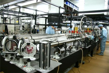


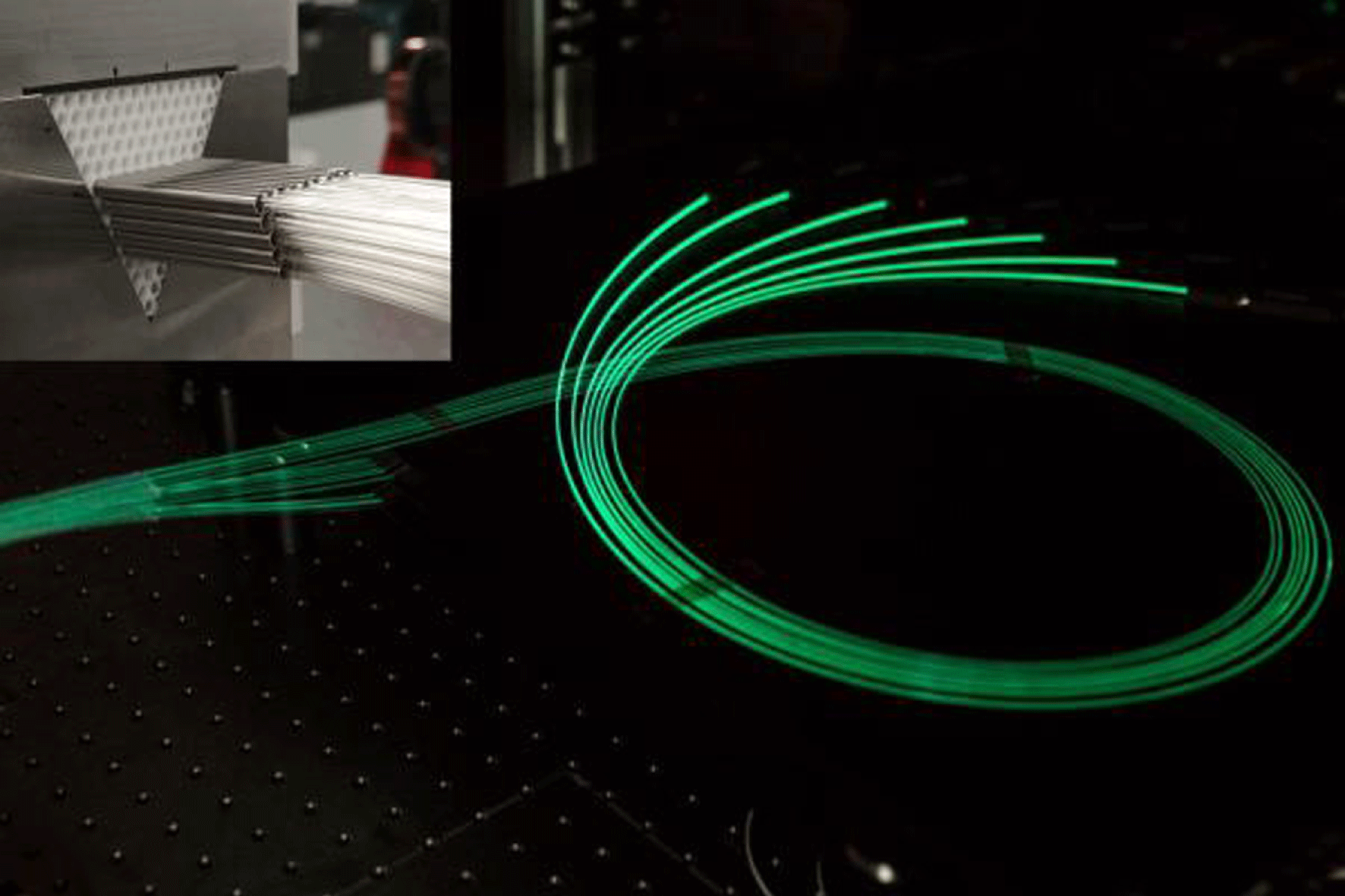


 Open access