


1 Introduction
The peak power density of lasers has increased significantly since the introduction of chirped-pulse amplification (CPA)[ Reference Strickland and Mourou 1 ]. High-power laser systems can generate extreme conditions of high temperature and pressure, making them indispensable tools in fields such as high-energy-density physics, materials science and inertial confinement fusion (ICF)[ Reference Mourou and Tajima 2 – Reference Batani, Colaïtis, Consoli, Danson, Gizzi, Honrubia, Kühl, Le Pape, Miquel, Perlado, Scott, Tatarakis, Tikhonchuk and Volpe 4 ]. Among these systems, picosecond-petawatt laser systems, which are characterized by high peak power and pulse energy, have become essential for advancing research and applications in these areas[ Reference Danson, Hillier, Hopps and Neely 5 – Reference Liu, Liu, Li, Leng and Li 7 ]. These systems typically comprise key components, including stretchers, amplifiers and compressors. Consequently, precise dispersion management is crucial to achieving a high power output and maintaining ultrashort pulse duration[ Reference Yakovlev 8 ]. However, factors such as mismatches between the stretcher and compressor, spectral variations and beam-pointing deviations can severely affect the accuracy and stability of the output pulse duration[ Reference Zhang, Yagi and Arisawa 9 ].
In recent years, significant progress has been made in pulse duration control and dispersion management at large-scale laser facilities. For instance, the advanced radiographic capability (ARC) laser system of the National Ignition Facility (NIF) at the Lawrence Livermore National Laboratory (LLNL) employs a tunable Treacy compensator to correct accumulated dispersion and integrates a pulse duration control module to adjust the pulse duration within a range of 1–30 ps[ Reference Moses, Lindl, Spaeth, Patterson, Sawicki, Atherton, Baisden, Lagin, Larson, MacGowan, Miller, Rardin, Roberts, Van Wonterghem and Wegner 10 – Reference Williams, Crane, Alessi, Boley, Bowers, Conder, Di Nicola, Di Nicola, Haefner, Halpin, Hamamoto, Heebner, Hermann, Herriot, Homoelle, Kalantar, Lanier, LaFortune, Lawson, Lowe-Webb, Morrissey, Nguyen, Orth, Pelz, Prantil, Rushford, Sacks, Salmon, Seppala, Shaw, Sigurdsson, Wegner, Widmayer, Yang and Zobrist 12 ]. Researchers have also investigated the effects of group delay dispersion (GDD) on pulse compression to control the picosecond pulse duration using a laser performance operation model and virtual beamline technologies[ Reference Sacks, McCandless, Feigenbaum, Di Nicola, Luke, Riedel, Learn and Kraines 13 ]. Similarly, the OMEGA-EP laser system employs a main amplifier chain and a folded grating compressor, enabling the delivery of kilojoule-level energy output. To support such high-performance outputs, an ultrashort pulse diagnostic system capable of precisely measuring pulse duration in the range of 0.4–12 ps has also been developed[ Reference Zuegel, Bahk, Bromage, Dorrer, Earley, Kessler, Kruschwitz, Morse, Maywar, Oliver, Qiao, Rigatti, Schmid, Shoup, Waxer and Kelly 14 – Reference Perez-Callejo, Bouffetier, Ceurvorst, Goudal, Klein, Svyatskiy, Holec, Perez-Martin, Falk, Casner, Weber, Kagan and Valdivia 16 ]. In the United Kingdom, the Vulcan laser system addresses third-order dispersion (TOD) using an acousto-optic programmable dispersive filter (AOPDF) and incorporates a compressor after the optical parametric chirped-pulse amplification (OPCPA) stage. This configuration enables precise measurements and optimization of the spectral phase and pulse contrast, thereby improving the stability of high-energy ultrashort pulse outputs[ Reference Archipovaite, Galletti, Oliveira, Galimberti, Frackiewicz, Musgrave and Hernandez-Gomez 17 ]. However, challenges such as beam-pointing instability, focal-spot fluctuations and nonlinear optical effects complicate the stable control of the pulse duration[ Reference Waxer, Dorrer, Kalb, Hill and Bittle 18 , Reference Guardalben, Barczys, Kruschwitz, Spilatro, Waxer and Hill 19 ]. Stability of ultrafast laser output is crucial in high-energy laser systems. For example, active control of compressor grating spacing has been shown to maintain high pulse duration stability over extended operation times in high-energy femtosecond platforms[ Reference Mielke, Gaudiosi, Hamamoto, Kim, Cline and Sapers 20 ]. Similarly, in multi-beam petawatt systems, reducing beam-pointing fluctuations via active stabilization improved peak power by over 50%[ Reference Tang, Guo, Yang, Jiang, Hua and Zong 21 ].
The SG-II 9th beamline, which is located at the Shanghai Institute of Optics and Fine Mechanics in China, can output pulse duration in the range of 1–10 ps, delivering an energy of 1000 J[ Reference He, Deng, Fan, Zhang, Lin, Wang, Zheng and Liu 22 , Reference Fan, Jiang, Wang, Wang, Huang, Lu, Wei, Li, Pan, Qiao, Wang, Cheng, Zhang, Huang, Xiao, Zhang, Li, Zhu and Lin 23 ]. To enhance the energy and pulse contrast, it employs a combination of high-gain ps-OPCPA and low-gain ns-OPCPA amplification schemes[ Reference Dorrer, Consentino, Irwin, Qiao and Zuegel 24 , Reference Xiao, Pan, Jiang, Wang, Du, Guo, Huang, Lu, Cui, Yang, Wei, Wang, Xiao, Li, Wang, Ouyang, Fan, Li and Zhu 25 ]. While the hybrid amplification scheme enhances system performance, it also increases the complexity of pulse duration control. Spectral fluctuations and beam-pointing deviations are key contributors to pulse duration instability. The former arises from spectral shearing, gain narrowing, nonlinear effects and spectral modulation during pulse shaping[ Reference Li, Theobald, Welsch and Sauerbrey 26 – Reference Shimada, Ishijima, Saiki, Sakuma, Inada and Nakagawa 29 ], while the latter contributes to residual group delay dispersion (RGDD), which arises from imperfect GDD compensation between the stretcher and compressor and directly affects the output pulse duration. As a result, the pre-compressed pulse duration fluctuates between 0.4 and 1 ps, leading to significant variations in peak power. Therefore, identifying the sources of pulse duration instability and providing a basis for subsequent system optimization have become critical tasks.
Therefore, this study investigated the key factors affecting pulse duration stability, aiming to provide theoretical support for further optimization of high-power laser systems. Firstly, the effect of the spectral characteristics on the pulse duration was examined. By combining theoretical simulations and experimental data, we quantified the effects of spectral variations on the pulse duration under different RGDD conditions. Next, the dispersion management of the system was analyzed, focusing on the distribution of GDD within the stretcher and compressor. The RGDD was calculated, and its influence on the pulse compression was clarified. Subsequently, the effects introduced by the beam-pointing deviation in the stretcher and compressor were evaluated, and their influence on the pulse duration stability was analyzed. Finally, optimization strategies were developed to address these challenges and improve the overall stability and reliability of the SG-II facility.
2 Numerical simulation
2.1 Effect of spectral variations on pulse duration
To evaluate the effect of spectral variations on the pulse duration, we employed numerical simulation methods based on the Fourier transform theory to analyze the relationship between the spectral width (full width at half maximum (FWHM)) and the pulse duration of a picosecond laser. Owing to the gain-narrowing effect in high-energy petawatt laser systems, the pulse shape under Fourier transform-limited (FTL) conditions is generally close to a Gaussian distribution in the time domain. Thus, assuming an FTL Gaussian laser pulse, we analyzed the relationship between the spectra and pulse in the time domain. The pulse duration of an FTL Gaussian laser pulse can be expressed as follows[ Reference Weiner 30 ]:
 $$\begin{align}{\tau}_{\mathrm{p}}=\frac{\kappa \cdot {\lambda_0}^2}{c\cdot \Delta \lambda },\end{align}$$
where λ
0 is the central wavelength of the pulse, $\Delta \lambda$
is the spectral width, c is the speed of light and
$\Delta \lambda$
is the spectral width, c is the speed of light and $\kappa$
is a constant with a value of 0.441. During pulse propagation, assuming that only phase changes affect the pulse envelope, the spectral phase is expanded as follows[
Reference White, Patterson, Combs, Price and Shepherd
31
]:
$\kappa$
is a constant with a value of 0.441. During pulse propagation, assuming that only phase changes affect the pulse envelope, the spectral phase is expanded as follows[
Reference White, Patterson, Combs, Price and Shepherd
31
]:
 $$\begin{align}\varphi \left(\omega \right)&=\varphi \left({\omega}_0\right)+{\varphi}^{\prime}\left({\omega}_0\right)\left(\omega -{\omega}_0\right)+\frac{1}{2}{\varphi}^{{\prime\prime}}\left({\omega}_0\right){\left(\omega -{\omega}_0\right)}^2\nonumber\\&\quad+\frac{1}{6}{\varphi}^{{\prime\prime\prime}}\left({\omega}_0\right){\left(\omega -{\omega}_0\right)}^3+\cdots,\end{align}$$
where the terms that are nonlinear with respect to ω are referred to as dispersions. Among these, ${\varphi}^{{\prime\prime}}\left({\omega}_0\right)$
represents a second-order dispersion. This is also known as GDD and introduces a linear chirp. Here,
${\varphi}^{{\prime\prime}}\left({\omega}_0\right)$
represents a second-order dispersion. This is also known as GDD and introduces a linear chirp. Here, ${\varphi}^{{\prime\prime\prime}}\left({\omega}_0\right)$
represents the TOD, which leads to asymmetric pulse distortion with oscillatory structures. For picosecond pulses, the pulse duration can be analytically expressed by considering only the effect of the GDD. Under this condition, the output pulse duration can be expressed as follows:
${\varphi}^{{\prime\prime\prime}}\left({\omega}_0\right)$
represents the TOD, which leads to asymmetric pulse distortion with oscillatory structures. For picosecond pulses, the pulse duration can be analytically expressed by considering only the effect of the GDD. Under this condition, the output pulse duration can be expressed as follows:
 $$\begin{align}T=\sqrt{{\left(\frac{0.441{\lambda_0}^2}{c\cdot \Delta \lambda}\right)}^2+{\left(\frac{4\ln 2\cdot {\varphi}^{{\prime\prime}}\left({\omega}_0\right)\cdot c\cdot \Delta \lambda }{0.441{\lambda_0}^2}\right)}^2}.\end{align}$$
According to Equation (3), we analyzed the effects of RGDD, spectral width and central wavelength on the output pulse duration. Figure 1(a) presents the variation of pulse duration with RGDD under different spectral width conditions. The results show that the pulse duration increases with the magnitude of RGDD. Figure 1(b) shows the impact of the spectral width variation on the pulse duration using a baseline spectral width of 5 nm. The results show that when the RGDD was 0 ps2, a 50% change in the spectral width resulted in a 100% variation in the pulse duration. Under other conditions, the same 50% change in the spectral width resulted in a maximum pulse duration variation of 50%. This highlights that the spectral width variation has a particularly pronounced impact on the FTL pulse duration, and its influence varies depending on the RGDD conditions. Moreover, the influence of central-wavelength variation (1050–1056 nm) on pulse duration was found to be minimal, with a maximum change of 0.6%.
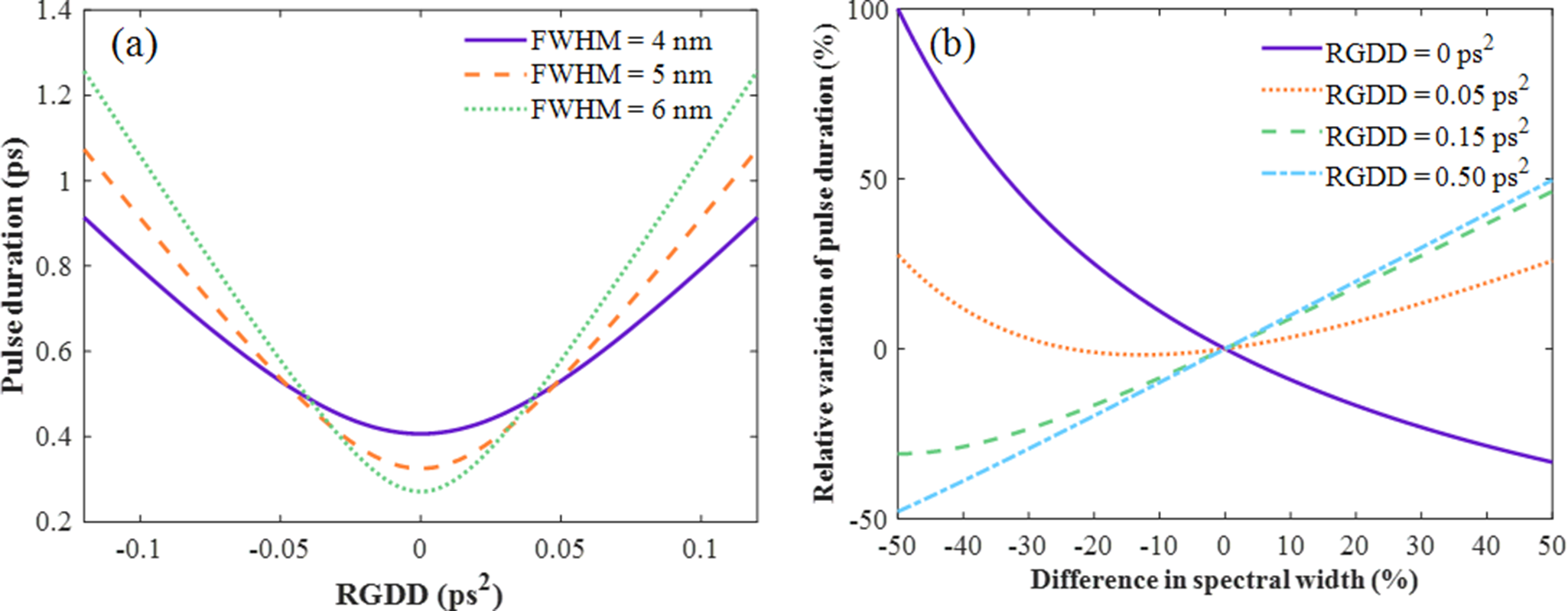
Figure 1 Effects of (a) RGDD and (b) spectral width on pulse duration, based on a baseline spectral width of 5 nm and a central wavelength of 1053 nm.
It can be concluded that a spectral width change from 2.5 to 7.5 nm may cause a pulse duration variation of up to 100% for FTL pulses, while the pulse duration variation under RGDD is relatively smaller. Importantly, the RGDD is influenced by the dispersion introduced by the stretcher and compressor, which can be significantly affected by beam-pointing deviations. Spectral width also plays an important role, particularly under low-dispersion conditions. Therefore, the following analysis investigates the effects of beam pointing and spectral characteristics on system dispersion and pulse duration.
2.2 Effect of beam-pointing deviation in the stretcher
In CPA laser systems, the beam must enter the stretcher and compressor at a specific incident angle to introduce a precise dispersion, enabling the desired temporal stretching and subsequent compression of the pulse. However, beam-pointing deviations directly alter the RGDD in the system, thereby affecting the output pulse duration stability. Two common types of stretchers are the Martinez-type and Offner-type configurations[ Reference Zuev, Ginzburg, Kochetkov, Shaykin and Yakovlev 32 , Reference Heebner, Acree, Alessi, Barnes, Bowers, Browning, Budge, Burns, Chang, Christensen, Crane, Dailey, Erbert, Fischer, Flegel, Golick, Halpin, Hamamoto, Hermann, Hernandez, Honig, Jarboe, Kalantar, Kanz, Knittel, Lusk, Molander, Pacheu, Paul, Pelz, Prantil, Rushford, Schenkel, Sigurdsson, Spinka, Taranowski, Wegner, Wilhelmsen, Wong and Yang 33 ]. The Offner-type stretcher, known for its compact layout and minimal optical aberrations, is used in our system. Its optical layout is illustrated in Figure 2. The stretcher employs a single-grating, folded geometry, consisting of a reflective diffraction grating, a convex mirror, a concave mirror, two roof mirrors and polarization-control elements. The input beam sequentially traverses a thin-film polarizer (TFP1), a half-wave plate (HWP), a Faraday rotator (FR), and a second TFP (TFP2), which together constitute a polarization-isolation stage. The beam is then diffracted by the grating and reflected sequentially by the concave mirror, the convex mirror and back to the concave mirror, before returning to the grating for a second diffraction.
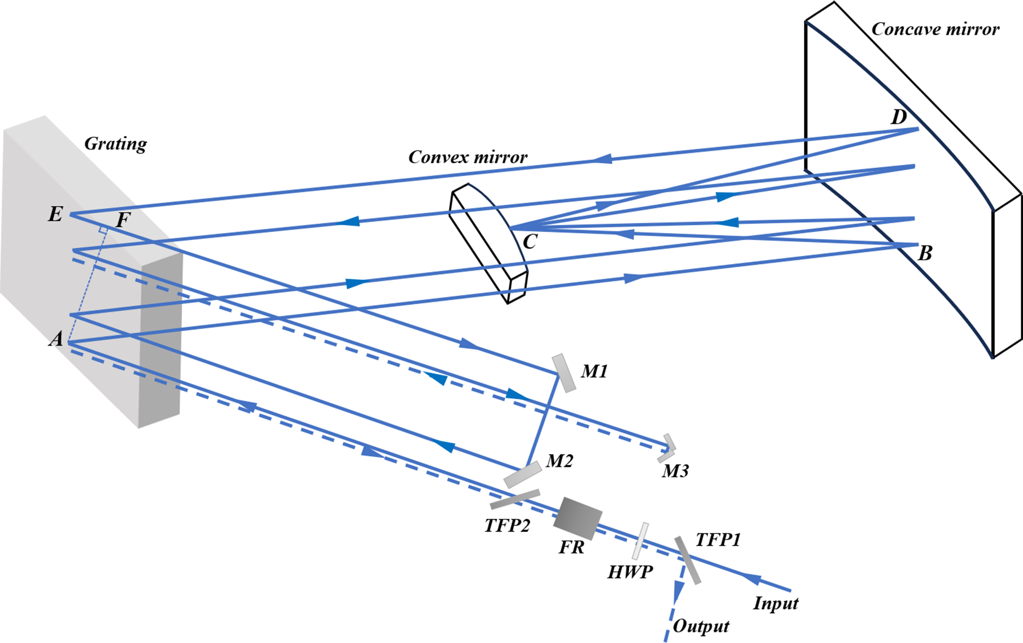
Figure 2 Configuration of the stretcher in the SG-II laser system (M1, M2, reflective mirror; M3, roof mirror; TFP, thin-film polarizer; FR, Faraday rotator; HWP, half-wave plate).
After the second diffraction, the beam is directed to a roof mirror (M1 and M2), introducing a vertical offset relative to the original optical plane. This vertical displacement enables the beam to re-enter the grating at a different height and undergo a third diffraction. The beam is then reflected again by the same mirror sequence (concave–convex–concave) and returns to the grating for a fourth diffraction. A small roof mirror (M3) retroreflects the beam approximately along the original path. Finally, due to the non-reciprocal polarization rotation introduced by the FR and HWP, the output beam is separated from the input path at TFP1. The beam undergoes eight diffractions at the grating while passing through the stretcher four times in total, achieving efficient temporal pulse stretching.
The concave mirror has a radius of curvature of 3.4 m. The convex mirror has a radius of curvature of 1.7 m. The distance from the grating to the concave mirror is 2.2 m, and the separation between the concave mirror and convex mirror is 1.7 m. Using the ray-tracing model, the spectral phase accumulated during a single pass through the stretcher can be derived as follows, where d denotes the grating groove period[ Reference Cheriaux, Rousseau, Salin, Chambaret, Walker and Dimauro 34 ]:
 $$\begin{align}\phi \left(\omega \right)=\frac{\omega \cdot \left(\overline{AB}+\overline{BC}+\overline{CD}+\overline{DE}+\overline{EF}\right)}{c}-\frac{2\pi \cdot \overline{AE}}{d}.\end{align}$$
Assuming a central wavelength of 1053 nm, spectral width of 5 nm, grating groove period of 1/1740 mm and incident angle of 71°, the stretcher was configured to provide four effective grating interactions. Based on Equation (4), calculations of high-order partial derivatives of $\phi \left(\omega \right)$
with respect to
$\phi \left(\omega \right)$
with respect to $\omega$
showed that the stretcher introduced a positive GDD of 275.59 ps2 and a negative TOD of –3.97 ps3. After that, the pulse is temporally broadened to approximately 3 ns.
$\omega$
showed that the stretcher introduced a positive GDD of 275.59 ps2 and a negative TOD of –3.97 ps3. After that, the pulse is temporally broadened to approximately 3 ns.
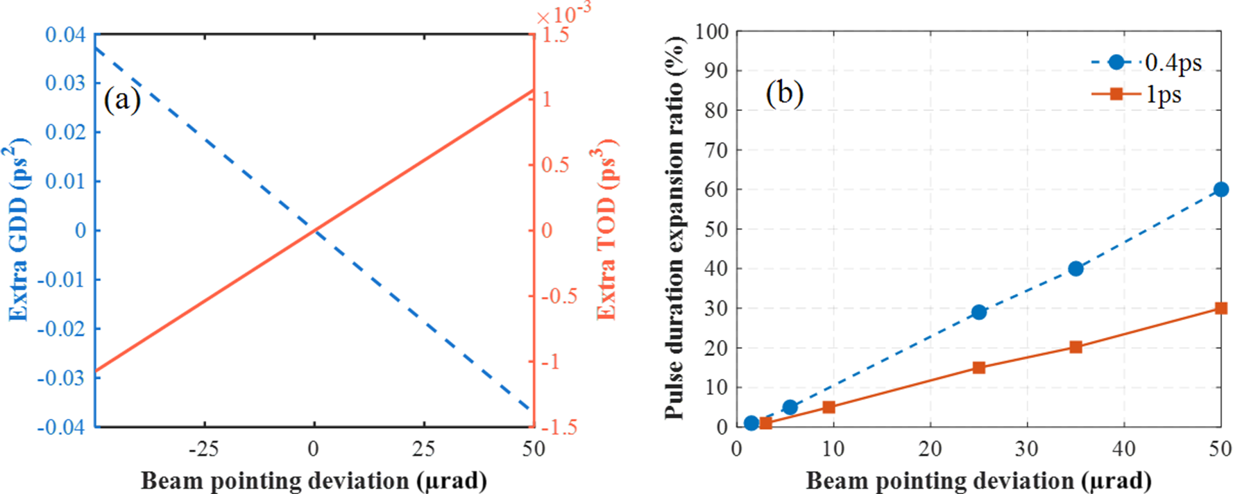
Thus, by treating the incident angle deviation as an independent variable, the additional GDD and TOD introduced by the incident angle deviation could be obtained. Figure 3(a) shows the variation of additional GDD and TOD with beam-pointing deviation. Therefore, a deviation of the incident angle of the beam in the stretcher caused a change in the RGDD of the system, resulting in an increase in pulse duration. For example, the pulse duration could be tuned to 0.4 ps (the shortest measured pulse duration) and 1 ps by adjusting the compressor. To evaluate the impact of beam-pointing deviation under these two pulse duration conditions, we first calculated the additional GDD using Equation (4), and then calculated the corresponding output pulse durations using Equation (3). The results are presented in Figure 3(b).

Figure 3 (a) Additional GDD and TOD introduced by beam-pointing deviation in the stretcher. (b) Effect of beam-pointing deviation on the output pulse duration expansion ratio.
Beam-pointing deviations in the stretcher led to different levels of pulse duration variation depending on the initial pulse width, with larger relative changes observed for 0.4 ps pulses compared to 1 ps pulses.
2.3 Effect of beam-pointing deviation in the compressor
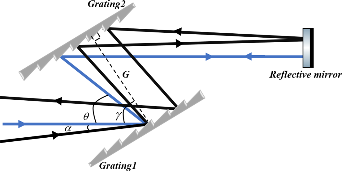
The optical path arrangement of the compressor is shown in Figure 4. It consisted of two gratings and a reflective mirror. When the beam was incident on the grating pair, the nominal incident angle was denoted as γ, and a small deviation from this angle was represented by α.

Figure 4 Optical layout of the compressor in the SG-II laser system. The blue line represents the beam entering with normal incidence, while the black line corresponds to the beam with a pointing deviation of α. Here, G is the distance between grating 1 and grating 2.
The grating equation under this geometry is given by the following:
 $$\begin{align}\sin \left(\gamma \right)+\sin \left(\gamma -\theta \right)= m\lambda /d,\end{align}$$
where θ represents the angle between the incident beam and its diffracted beam, and the diffraction angle is therefore given by γ – θ. Here, m is the diffraction order, λ is the wavelength, d is the grating groove period (1/1740 mm) and G denotes the perpendicular distance between the gratings. A small deviation in the incident angle changes the left-hand side of the equation, and thus alters the resulting diffraction angle θ. The spectral phase introduced by the grating pair can be expressed as follows[ Reference Li, Rao, Leng, Chen and Dai 35 ]:
 $$\begin{align}{\phi}_1\left(\omega \right)=\frac{\omega }{c}\cdot \frac{G\cdot \left(1+\cos \theta \right)}{\cos \left(\gamma -\theta \right)}-2\pi \frac{G\tan \left(\gamma -\theta \right)}{d}.\end{align}$$
By taking the second- and third-order partial derivatives of ${\phi}_1\left(\omega \right)$
with respect to
${\phi}_1\left(\omega \right)$
with respect to $\omega$
, the GDD and TOD introduced by the beam passing through the grating pair can be expressed as follows[
Reference Treacy
36
]:
$\omega$
, the GDD and TOD introduced by the beam passing through the grating pair can be expressed as follows[
Reference Treacy
36
]:
 $$\begin{align} \mathrm{GDD}=-\frac{G{\lambda}^3}{2\pi {c}^2{d}^2\cdot {\left(1-{\left(\frac{\lambda }{d}-\sin \gamma \right)}^2\right)}^{3/2}},\nonumber\\ {} \mathrm{TOD}=\frac{3G{\lambda}^4}{4{\pi}^2{c}^3{d}^2}\cdot \frac{1+\frac{\lambda \sin \gamma }{d}-{\sin}^2\gamma }{{\left(1-{\left(\frac{\lambda }{d}-\sin \gamma \right)}^2\right)}^{5/2}}.\end{align}$$
As shown in Figure 4, the two-grating folded compressor introduced an additional dispersion owing to the beam-pointing deviations. In this configuration, beam-pointing deviation alters the incident angle on the first grating, resulting in a deviation of the diffraction angle from its design value. After reflection from the reflective mirror and re-entry into the second grating, the angular deviations of the forward and return beam paths are opposite in sign, leading to partial cancellation of the dispersion error caused by pointing.
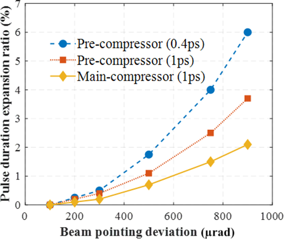
The specific impact of the beam-pointing deviation on the compressed pulse duration can be quantified based on Equations (3) and (7). Through theoretical simulations, we analyzed the effects of beam-pointing deviations on the output pulse duration in the pre-compressor (G = 2.10 m) and main compressor (G = 1.99 m), and the results are presented in Figure 5. In the pre-compressor, for a pulse duration of 0.4 ps, the change in pulse duration was nearly 0% with a beam-pointing deviation of 100 μrad but increased to 6% as the deviation reached 900 μrad. Likewise, for a pulse duration of 1 ps, the pulse duration remained nearly unchanged at 100 μrad but exhibited a 3.7% increase at 900 μrad. In addition, the gain-narrowing effect of the amplifier led to a rise in the final output pulse duration. Therefore, a pulse duration of 1 ps was used in the main compressor for the analysis. In the main compressor, a beam-pointing deviation of 900 μrad corresponded to a pulse duration change of 2.1%.

Figure 5 Effects of beam-pointing deviations on the output pulse duration of the pre-compressor (dashed lines) and main compressor (solid line).
In conclusion, we systematically analyzed the additional GDD and TOD introduced by beam-pointing deviations in both the stretcher and compressor and quantified their respective impacts on the output pulse duration under different initial pulse duration conditions. To evaluate the contributions of various factors to the overall pulse duration deviation, we defined the following terms:
-
(1) the deviation caused by changes in the central wavelength was $\delta_1$
;
$\delta_1$
; -
(2) the deviation caused by variations in the spectral width was
$\delta_2$
; -
(3) the deviation introduced by beam-pointing deviations in the stretcher was
$\delta_3$
; -
(4) the deviation introduced by beam-pointing deviations in the compressor was
$\delta_4$
.
Thus, the total pulse duration deviation after compression can be expressed as follows:
 $$\begin{align}{\delta}_5=\sqrt{{\delta_1}^2+{\delta_2}^2+{\delta_3}^2+{\delta_4}^2}.\end{align}$$
The above analysis revealed that the compressed pulse duration deviation was a cumulative effect of multiple factors, with the spectral variations and beam-pointing deviations in the stretcher having the most significant influence on the output pulse duration.
3 Experimental results and analysis
To comprehensively evaluate the impacts of dispersion management, spectral variations and beam-pointing deviations on the performance of a laser system, we analyzed the dispersion management strategy employed in the SG-II 9th system. Next, we measured and examined the stability of the spectra and pulse duration of the OPCPA output. Finally, we investigated the effects of beam-pointing deviations on the pulse duration in the stretcher and compressor.
3.1 Dispersion management of the SG-II 9th system
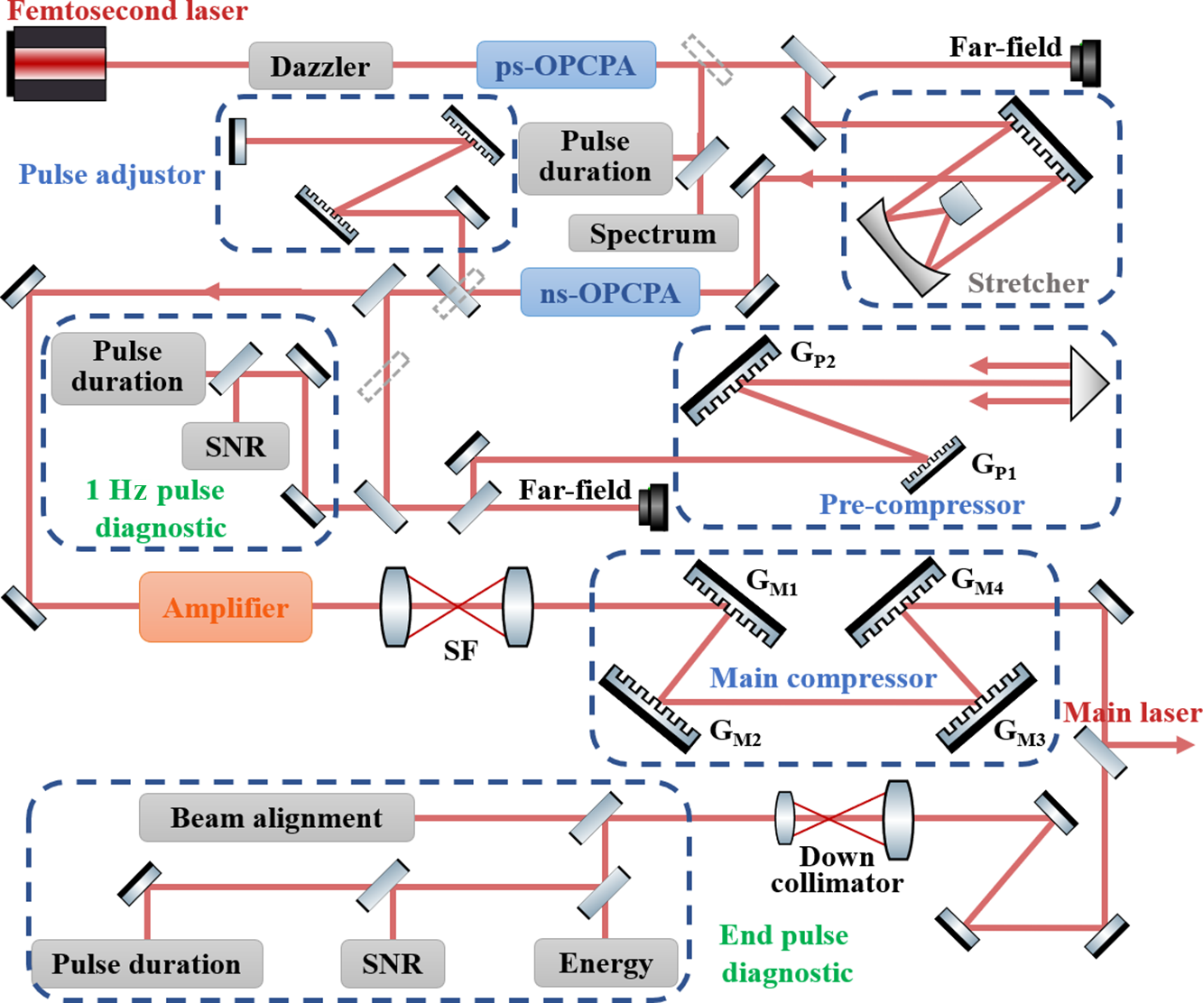
The SG-II 9th laser system developed by the Key Laboratory of High Power Laser and Physics is an important scientific facility that supports various areas of physics research. The optical layout of this system is shown in Figure 6. A femtosecond mode-locked laser is employed as the seed source to generate pulses with a central wavelength of 1053 nm and a pulse duration of 250 fs. These pulses first pass through a Dazzler (AOPDF, FASTLITE) and are then injected into the ps-OPCPA stage. Afterward, the pulses are stretched to the nanosecond scale using an Offner-type stretcher, and subsequently amplified to the millijoule level by the ns-OPCPA. Subsequently, the pulses are initially compressed using a pulse adjustor (fine-tuning compressor). In the following step, rail-controlled mirrors direct the beam to the pre-compressor, which monitors the key parameters of the compressed pulse, including the pulse duration, energy and pulse contrast. After the initial compression, the beam passes through rod and slab amplifiers for further energy amplification. Finally, the laser beam is compressed using the main compressor. Subsequently, 99% of the compressed output is delivered as a high-power picosecond pulse, whereas the remaining 1% is extracted and directed toward the diagnostic system. To ensure the high precision and stability of the output pulse duration, the system precisely controls the dispersion. By adjusting the pre-compressor, the SG-II 9th system achieves continuous tunability of the pulse duration between 0.4 and 10 ps[ Reference Ouyang, Cui, Zhu, Zhu and Zhu 37 ].

Figure 6 Schematic of the SG-II 9th laser system (dazzler, acousto-optic programmable dispersive filter; pulse adjustor, fine-tuning compressor; SNR, signal-to-noise ratio; SF, spatial filter; GP1, GP2, GM1–GM4, gratings).
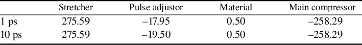
The above analysis emphasizes the impact of the RGDD on the pulse duration in a CPA/OPCPA laser system. Consequently, we conducted a detailed analysis of the dispersion introduced by each component in the SG-II 9th system, and the corresponding data are summarized in Table 1. In this analysis, 1 and 10 ps were selected as typical pulse durations of the system. The results indicate that pulse duration depends on RGDD levels, emphasizing the need for effective dispersion management.
Table 1 Dispersion distribution of the SG-II 9th system (in ps2).

In addition, the residual third-order dispersion (RTOD) after the compressor was found to have a negligible effect on the pulse duration for picosecond pulses. While its effect on pulse duration is limited, excessive RTOD may still introduce subtle distortions to the pulse envelope, slightly degrading pulse contrast[ Reference Jiang, Zhang and Hasama 38 – Reference Stuart, Robinson, Hillier, Hopps, Parry, Musgrave, Nersisyan, Sharba, Zepf and Smith 40 ].
3.2 Spectra and pulse duration stability measurements of the SG-II 9th system
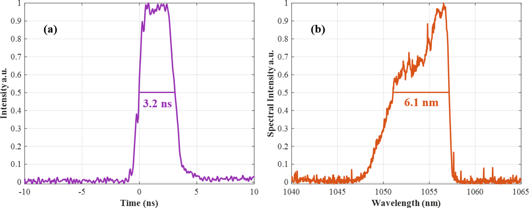
To investigate the influence of spectral characteristics on pulse duration stability, we measured the temporal envelope and the corresponding spectra of the pulse after the stretcher. As shown in Figure 7, the measured temporal profile exhibits a pulse duration of 3.2 ns, while the spectral width of the pulse is approximately 6.1 nm. Both the temporal and spectral profiles demonstrate good stability at this stage.

Figure 7 (a) Temporal envelope of the pulse after the stretcher, with a pulse duration of 3.2 ns measured using a 5 GHz bandwidth oscilloscope. (b) Corresponding spectrum with a spectral width of 6.1 nm.
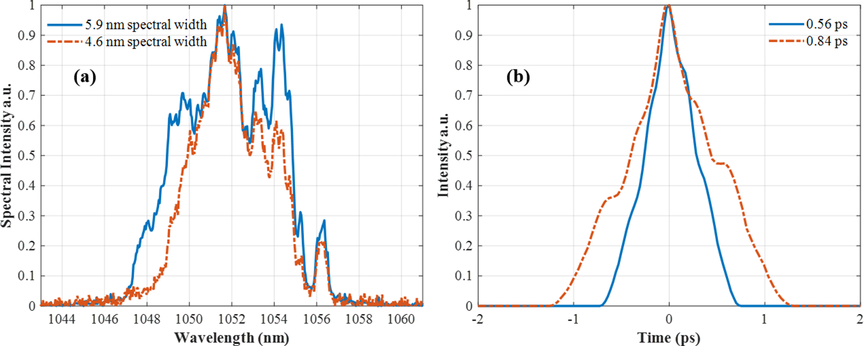
Then, we measured the output spectra and pulse duration of the ps- and ns-OPCPA outputs. The laser repetition frequency was set to 1 Hz. Spectra measurements were performed using a fiber-coupled spectrometer, providing sufficient resolution to capture fine spectral variations. For pulse duration characterization, we employed a single-shot autocorrelator, which enables pulse duration measurement of individual pulses. These diagnostics ensured that both spectral fluctuations and temporal instabilities could be accurately monitored and analyzed[ Reference Wong and Trebino 41 – Reference Salin, Georges, Roger and Brun 43 ]. We simultaneously measured the output spectra and pulse durations of single-shot pulses after the compressor. As shown in Figure 8, spectral widths of 5.9 and 4.6 nm correspond to the FWHM of the autocorrelation function (ACF) trace, measured to be 0.56 and 0.84 ps, respectively. The observed relationship between the spectral width and the pulse duration is consistent with the Fourier transform described by Equation (1), further supporting the interpretation that spectral fluctuations contribute to pulse duration instabilities in the system.

Figure 8 (a) Measured spectra and (b) corresponding autocorrelation traces of single-shot pulses after the compressor. For spectral widths of 5.9 and 4.6 nm, the FWHM values of the ACF trace are 0.56 and 0.84 ps, respectively, yielding pulse durations of 0.4 and 0.6 ps based on Gaussian fitting.
Figures 9(a) and 9(b) show the spectral and pulse duration measurements of the ps-OPCPA output (energy of 200 μJ) 1 and 4 h after the laser system was turned on. A total of consecutive 80 laser shots were selected to balance representative statistical sampling and manageable data complexity. The root mean square (RMS) values of the spectral widths were 2.4% and 2.1%, respectively, whereas the RMS values of the corresponding pulse durations were 4.8% and 4.5%, respectively. It can be observed that the pulse duration deviation was approximately twice the spectral width deviation, which agreed with the simulation results shown in Figure 1(b). Furthermore, Figures 9(c) and 9(d) present the spectral and pulse duration measurements of the ns-OPCPA output (energy of 4 mJ) 1 and 4 h after the laser system was turned on. The RMS values of the spectral widths were 6.4% and 8.6%, respectively, whereas the RMS values of the corresponding pulse durations were 20.7% and 23.6%, respectively. For reference, a spectral width deviation of 8.6% was associated with a calculated pulse duration variation of approximately 9%, consistent with the observed trend.
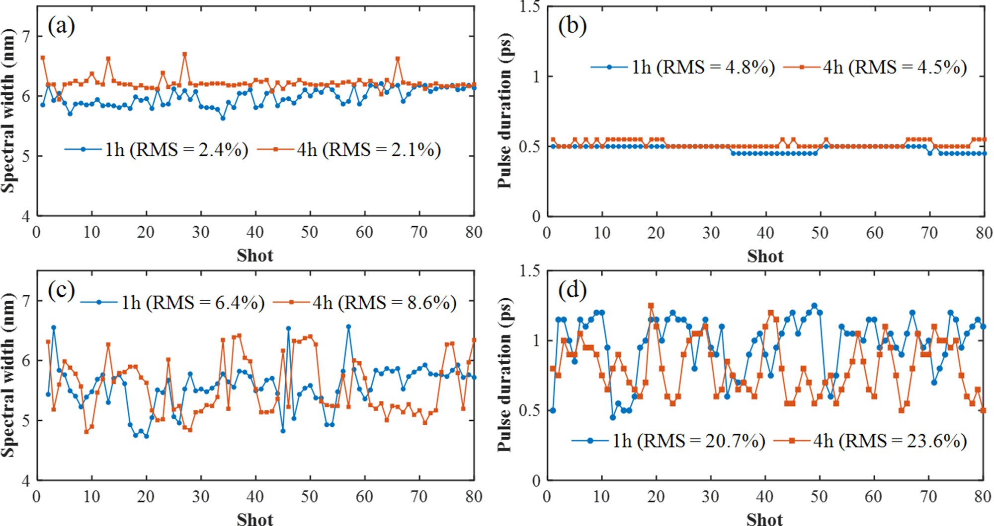
Figure 9 (a) Spectral width and (b) pulse duration stability measurement results for the ps-OPCPA output. (c) Spectral width and (d) pulse duration stability measurement results for the ns-OPCPA output.
However, the measured pulse duration deviation was significantly larger than the theoretical value. This discrepancy may be attributed to factors such as beam-pointing deviations, nonlinear amplification effects and spectral gain narrowing, which were introduced as the chirped pulse passed through the stretcher, ns-OPCPA system and pre-compressor. Among these factors, beam-pointing deviations directly affected the RGDD of the system, which was likely the primary cause of the larger RMS pulse duration observed in the ns-OPCPA stage. These results complement the theoretical analysis, which provided a simplified yet useful framework for interpreting the observed pulse duration fluctuations.
In addition, the gain-narrowing effect significantly reduced the spectral width of the end output pulse to 3.4 nm after the main compressor. The experimental results revealed the spectral stability characteristics across different stages of the CPA/OPCPA-based high-power laser system, highlighting the importance of managing spectral evolution to preserve pulse duration. Therefore, careful control of spectral shaping throughout the amplification and compression stages is essential to ensure long-term system stability and optimal performance[ Reference Bleotu, Wheeler, Mironov, Ginzburg, Masruri, Naziru, Secareanu, Ursescu, Perez, De Sousa, Badarau, Veuillot, Audebert, Khazanov and Mourou 44 , Reference Su, Ma, Zhou, Chen, Wang, Ma, Wu and Xu 45 ].
3.3 Beam far-field pointing measurements of the stretcher and pre-compressor
To validate the theoretical analysis, we measured the far-field beam-pointing deviations in the stretcher and pre-compressor. The far-field image was captured at a downstream target plane using a collimation monitoring module, which receives the transmitted beam from a beamsplitter placed before the stretcher or pre-compressor. In the experimental setup, the beam diameter is approximately 10 mm prior to entering the stretcher and about 20 mm prior to entering the compressor. Within both the stretcher and compressor, reflective gratings induce angular dispersion, causing the beam to expand into an elongated, stripe-like spatial profile.
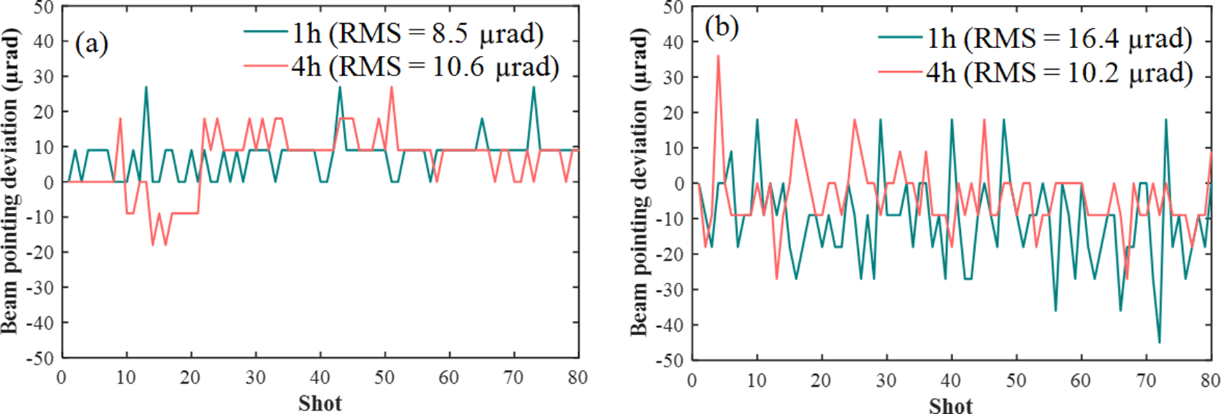
Far-field pointing data in the stretcher were measured 1 and 4 h after the laser system was turned on, and the results are shown in Figure 10(a). The RMS value of the beam-pointing deviation was 8.5 μrad 1 h after startup and it increased slightly to 10.6 μrad 4 h after startup. The significant influence of beam-pointing deviations at the stretcher input on pulse duration is studied in this section. The measured magnitude of a 27 μrad deviation can induce a pulse duration variation of approximately 30% for an initial pulse duration of 0.4 ps, and about 15% for 1 ps, according to the theoretical analysis shown in Figure 3(b). This value reflects the largest observed deviation and highlights the potential worst-case impact of beam-pointing instability. We also monitored the beam-pointing deviations in the pre-compressor, as shown in Figure 10(b). The RMS values were 16.4 and 10.2 μrad 1 and 4 h after startup, respectively.

Figure 10 Far-field beam-pointing fluctuations measured in the (a) stretcher and (b) pre-compressor over 80 consecutive laser shots. Data acquisition was performed on a single-shot basis at a repetition rate of 1 Hz.
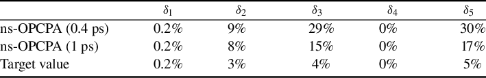
Based on the experimental data, we analyzed the pulse duration deviations under different pulse duration conditions, with the results listed in Table 2. For a near-FTL pulse duration of 0.4 ps, the pulse duration deviation (δ 1) caused by central-wavelength variations was 0.2% The deviation (δ 2) caused by spectral width variations was 9%, while the pulse duration deviation (δ 3) introduced by beam-pointing deviations in the stretcher was 29%. The pulse duration deviation due to beam-pointing deviations in the compressor was negligible (δ 4 = 0%). According to Equation (8), the total pulse duration deviation (δ 5) was 30%.
Table 2 Analysis of compressed pulse duration stability under different pulse duration conditions.

Similarly, for a pulse duration of 1 ps, the deviation (δ 1) caused by central-wavelength variations was 0.2%, whereas that (δ 2) caused by spectral width variations was 8%. The pulse duration deviation (δ 3) introduced by beam-pointing deviations in the stretcher was 15%, and the pulse duration deviation (δ 4) in the compressor was 0%. The total pulse duration deviation (δ 5) was 17%.
In summary, achieving high pulse duration stability within 5% requires the simultaneous optimization of the spectral management and beam-pointing stability while accounting for the practical operating conditions of the laser system. Based on the analysis and experimental data, for a pulse duration of 0.4 ps, the spectral width deviation must be controlled to within 0.3 nm. In contrast, the beam-pointing deviation should be limited to within 5 μrad. These results underscore the necessity of comprehensively evaluating the effects of various parameters, particularly emphasizing the critical importance of achieving higher precision and stability in spectral and beam-pointing control. The current analysis and measurements account for approximately 10% of the RMS pulse duration fluctuation, indicating that additional instability factors may also contribute.
4 Conclusions
In conclusion, we systematically investigated the factors influencing the pulse duration stability of the SG-II facility through a combination of theoretical simulations and experimental validation. Firstly, we identified the significant influence of spectral width variations on the pulse duration stability. For a 1 ps pulse, a 50% change in the spectral width results in a 40% variation in the pulse duration, whereas for a near-FTL pulse duration of 0.4 ps, the same spectral width variation leads to a pulse duration change of up to 100%. In addition, beam-pointing deviations in the stretcher were identified as a major factor contributing to pulse duration fluctuations, primarily owing to variations in the RGDD of the laser system. The theoretical analysis and experimental results demonstrated that beam-pointing deviation in the stretcher had a significant impact on the stability of the pulse duration. For example, when the beam-pointing deviation reached 27 μrad, the pulse duration variation could be as high as 30%. Therefore, it is necessary to improve the beam-pointing stability and precision of stretchers. In contrast, the geometric design of the compressor exhibited properties that significantly mitigated the impact of beam-pointing deviations. These findings underscore the critical importance of precise spectral management and provide essential guidelines for controlling the beam-pointing accuracy to maintain pulse duration stability. Furthermore, this study offers operating tolerance ranges for maintaining pulse duration stability. Specific optimization parameters such as limiting spectral width deviations to within 0.3 nm and beam-pointing deviations to within 5 μrad are proposed based on the SG-II 9th laser system. This could be useful for understanding the impact of each parameter on the pulse duration stability in high-power laser systems and guiding their optimization to improve the overall system performance.
This study provides a preliminary analysis of pulse duration fluctuations in high-power laser systems, which may offer useful guidance for improving spectral management and beam-pointing control in CPA/OPCPA-based systems. While this work primarily focused on the spectral width and beam-pointing deviations, future investigations are expected to explore the influence of complex nonlinear effects, such as self-phase modulation and cross-phase modulation, on the pulse duration stability and overall system performance. The goal of these efforts should be to further optimize high-power laser systems for advanced applications, including attosecond-pulse generation, supercontinuum generation and high-energy-density physics experiments.
Acknowledgments
This work was partially supported by the Strategic Priority Research Program of the Chinese Academy of Sciences (Grant No. XDA25020306) and the National Natural Science Foundation of China (NSFC) (Grant No. 62175247).


 Open access