


1 Introduction
The objective of the Helmholtz International Beamline for Extreme Fields (HiBEF) user consortium[
1
] is to contribute and operate a variety of experimental setups using the high energy density (HED) instrument[
Reference Nakatsutsumi and Tschentscher
2
] of the European X-ray free electron laser (EuXFEL) facility. The EuXFEL is an X-ray free electron laser (FEL) facility providing worldwide unique ultrashort and extremely bright X-ray flashes[
Reference Tschentscher, Bressler, Grünert, Madsen, Mancuso, Meyer, Scherz, Sinn and Zastrau
3
,
Reference Decking, Abeghyan, Abramian, Abramsky, Aguirre, Albrecht, Alou, Altarelli, Altmann, Amyan, Anashin, Apostolov, Appel, Auguste, Ayvazyan, Baark, Babies, Baboi, Bak, Balandin, Baldinger, Baranasic, Barbanotti, Belikov, Belokurov, Belova, Belyakov, Berry, Bertucci, Beutner, Block, Blöcher, Böckmann, Bohm, Böhnert, Bondar, Bondarchuk, Bonezzi, Borowiec, Bösch, Bösenberg, Bosotti, Böspflug, Bousonville, Boyd, Bozhko, Brand, Branlard, Briechle, Brinker, Brinker, Brinkmann, Brockhauser, Brovko, Brück, Brüdgam, Butkowski, Büttner, Calero, Castro-Carballo, Cattalanotto, Charrier, Chen, Cherepenko, Cheskidov, Chiodini, Chong, Choroba, Chorowski, Churanov, Cichalewski, Clausen, Clement, Cloué, Cobos, Coppola, Cunis, Czuba, Czwalinna, D’Almagne, Dammann, Danared, de Zubiaurre Wagner, Delfs, Delfs, Dietrich, Dietrich, Dohlus, Dommach, Donat, Dong, Doynikov, Dressel, Duda, Duda, Eckoldt, Ehsan, Eidam, Eints, Engling, Englisch, Ermakov, Escherich, Eschke, Saldin, Faesing, Fallou, Felber, Fenner, Fernandes, Fernández, Feuker, Filippakopoulos, Floettmann, Fogel, Fontaine, Francés, Freijo Martin, Freund, Freyermuth, Friedland, Fröhlich, Fusetti, Fydrych, Gallas, García, Garcia-Tabares, Geloni, Gerasimova, Gerth, Geßler, Gharibyan, Gloor, Głowinkowski, Goessel, Gołębiewski, Golubeva, Grabowski, Graeff, Grebentsov, Grecki, Grevsmuehl, Gross, Grosse-Wortmann, Grünert, Grunewald, Grzegory, Feng, Guler, Gusev, Gutierrez, Hagge, Hamberg, Hanneken, Harms, Hartl, Hauberg, Hauf, Hauschildt, Hauser, Havlicek, Hedqvist, Heidbrook, Hellberg, Henning, Hensler, Hermann, Hidvégi, Hierholzer, Hintz, Hoffmann, Hoffmann, Hoffmann, Holler, Hüning, Ignatenko, Ilchen, Iluk, Iversen, Iversen, Izquierdo, Jachmann, Jardon, Jastrow, Jensch, Jensen, Jeżabek, Jidda, Jin, Johansson, Jonas, Kaabi, Kaefer, Kammering, Kapitza, Karabekyan, Karstensen, Kasprzak, Katalev, Keese, Keil, Kholopov, Killenberger, Kitaev, Klimchenko, Klos, Knebel, Koch, Koepke, Köhler, Köhler, Kohlstrunk, Konopkova, Konstantinov, Kook, Koprek, Körfer, Korth, Kosarev, Kosiński, Kostin, Kot, Kotarba, Kozak, Kozak, Kramert, Krasilnikov, Krasnov, Krause, Kravchuk, Krebs, Kretschmer, Kreutzkamp, Kröplin, Krzysik, Kube, Kuehn, Kujala, Kulikov, Kuzminych, La Civita, Lacroix, Lamb, Lancetov, Larsson, Le Pinvidic, Lederer, Lensch, Lenz, Leuschner, Levenhagen, Li, Liebing, Lilje, Limberg, Lipka, List, Liu, Liu, Lorbeer, Lorkiewicz, Lu, Ludwig, Machau, Maciocha, Madec, Magueur, Maiano, Maksimova, Malcher, Maltezopoulos, Mamoshkina, Manschwetus, Marcellini, Marinkovic, Martinez, Martirosyan, Maschmann, Maslov, Matheisen, Mavric, Meißner, Meissner, Messerschmidt, Meyners, Michalski, Michelato, Mildner, Moe, Moglia, Mohr, Mohr, Möller, Mommerz, Monaco, Montiel, Moretti, Morozov, Morozov, Mross, Mueller, Müller, Müller, Müller, Munilla, Münnich, Muratov, Napoly, Näser, Nefedov, Neumann, Neumann, Ngada, Noelle, Obier, Okunev, Oliver, Omet, Oppelt, Ottmar, Oublaid, Pagani, Paparella, Paramonov, Peitzmann, Penning, Perus, Peters, Petersen, Petrov, Petrov, Pfeiffer, Pflüger, Philipp, Pienaud, Pierini, Pivovarov, Planas, Pławski, Pohl, Polinski, Popov, Prat, Prenting, Priebe, Pryschelski, Przygoda, Pyata, Racky, Rathjen, Ratuschni, Regnaud-Campderros, Rehlich, Reschke, Robson, Roever, Roggli, Rothenburg, Rusiński, Rybaniec, Sahling, Salmani, Samoylova, Sanzone, Saretzki, Sawlanski, Schaffran, Schlarb, Schlösser, Schlott, Schmidt, Schmidt-Foehre, Schmitz, Schmökel, Schnautz, Schneidmiller, Scholz, Schöneburg, Schultze, Schulz, Schwarz, Sekutowicz, Sellmann, Semenov, Serkez, Sertore, Shehzad, Shemarykin, Shi, Sienkiewicz, Sikora, Sikorski, Silenzi, Simon, Singer, Singer, Sinn, Sinram, Skvorodnev, Smirnow, Sommer, Sorokin, Stadler, Steckel, Steffen, Steinhau-Kühl, Stephan, Stodulski, Stolper, Sulimov, Susen, Świerblewski, Sydlo, Syresin, Sytchev, Szuba, Tesch, Thie, Thiebault, Tiedtke, Tischhauser, Tolkiehn, Tomin, Tonisch, Toral, Torbin, Trapp, Treyer, Trowitzsch, Trublet, Tschentscher, Ullrich, Vannoni, Varela, Varghese, Vashchenko, Vasic, Vazquez-Velez, Verguet, Vilcins-Czvitkovits, Villanueva, Visentin, Viti, Vogel, Volobuev, Wagner, Walker, Wamsat, Weddig, Weichert, Weise, Wenndorf, Werner, Wichmann, Wiebers, Wiencek, Wilksen, Will, Winkelmann, Winkowski, Wittenburg, Witzig, Wlk, Wohlenberg, Wojciechowski, Wolff-Fabris, Wrochna, Wrona, Yakopov, Yang, Yang, Yurkov, Zagorodnov, Zalden, Zavadtsev, Zavadtsev, Zhirnov, Zhukov, Ziemann, Zolotov, Zolotukhina, Zummack and Zybin
4
]. The HiBEF is organized as an international user consortium to ensure scientific and technical excellence of the provided infrastructure, which will serve the whole scientific community. The field of interest, HED science, includes plasma physics, planetary science, high-pressure and strong-field physics, magnetism and correlated electron systems, as well as material dynamics. The HiBEF contributes and operates two large laser systems: a high-energy laser, DIPOLE-100X[
Reference Mason, Banerjee, Smith, Butcher, Phillips, Höppner, Möller, Ertel, De Vido, Hollingham, Norton, Tomlinson, Zata, Merchan, Hooker, Tyldesley, Toncian, Hernandez-Gomez, Edwards and Collier
5
], developed and manufactured by UKRI-STFC-RAL-CLF, UK, and a high-intensity laser – the Relativistic Laser at XFEL (ReLaX). The ReLaX laser is based on a commercial 300 TW titanium sapphire system. A wide array of high-intensity laser facilities currently exists around the world, covering a range of power up to multi-PW level[
Reference Danson, Haefner, Bromage, Butcher, Chanteloup, Chowdhury, Galvanauskas, Gizzi, Hein, Hillier, Hopps, Kato, Khazanov, Kodama, Korn, Li, Li, Limpert, Ma, Nam, Neely, Papadopoulos, Penman, Qian, Rocca, Shaykin, Siders, Spindloe, Szatmári, Trines, Zhu, Zhu and Zuegel
6
], with a recent demonstration of the generation of pulses up to the 10 PW[
Reference Lureau, Matras, Chalus, Derycke, Morbieu, Radier, Casagrande, Laux, Ricaud, Rey, Pellegrina, Richard, Boudjemaa, Simon-Boisson, Baleanu, Banici, Gradinariu, Caldararu, De Boisdeffre, Ghenuche, Naziru, Kolliopoulos, Neagu, Dabu, Dancus and Ursescu
7
] and peak laser intensities[
Reference Yoon, Kim, Choi, Sung, Lee, Lee and Nam
8
] above ${10}^{23}\kern0.22em \mathrm{W}/{\mathrm{cm}}^2$
. However, the number of FELs in the hard X-ray regime is limited[
Reference Geloni, Huang and Pellegrini
9
], which makes the combination of high-power lasers and FELs a unique platform of research. In combination with the EuXFEL beam, it will enable novel investigations in a wide array of areas: properties of highly excited solids, HED states of matter[
Reference Kritcher, Swift, Döppner, Bachmann, Benedict, Collins, DuBois, Elsner, Fontaine, Gaffney, Hamel, Lazicki, Johnson, Kostinski, Kraus, MacDonald, Maddox, Martin, Neumayer, Nikroo, Nilsen, Remington, Saumon, Sterne, Sweet, Correa, Whitley, Falcone and Glenzer
10
,
Reference Kraus, Vorberger, Pak, Hartley, Fletcher, Frydrych, Galtier, Gamboa, Gericke, Glenzer, Granados, MacDonald, MacKinnon, McBride, Nam, Neumayer, Roth, Saunders, Schuster, Sun, van Driel, Döppner and Falcone
11
], probing quantum electrodynamics effects[
Reference Schlenvoigt, Heinzl, Schramm, Cowan and Sauerbrey
12
–
Reference Karbstein
14
], ionization dynamics at high intensities[
Reference Huang, Kluge and Cowan
15
], relativistic laser plasma interaction[
Reference Wang, Toncian, Wei and Arefiev
16
], energetic particle propagation in matter[
Reference Huang, Bussmann, Kluge, Lei, Yu and Cowan
17
–
Reference Chen, Atzeni, Gangolf, Gauthier, Higginson, Hua, Kim, Mangia, McGuffey, Marquès, Riquier, Pépin, Shepherd, Willi, Beg, Deutsch and Fuchs
19
], the production of secondary high-energy photon and particle radiation sources[
Reference Hatchett, Brown, Cowan, Henry, Johnson, Key, Koch, Langdon, Lasinski, Lee, Mackinnon, Pennington, Perry, Phillips, Roth, Sangster, Singh, Snavely, Stoyer, Wilks and Yasuike
20
–
Reference Stark, Toncian and Arefiev
22
] for material and biological[
Reference Karsch, Beyreuther, Passos, Pawelke and Löck
23
] and medical sciences[
Reference Brack, Kroll, Gaus, Bernert, Beyreuther, Cowan, Karsch, Kraft, Kunz-Schughart, Lessmann, Metzkes-Ng, Obst-Huebl, Pawelke, Rehwald, Schlenvoigt, Schramm, Sobiella, Szabó, Ziegler and Zeil
24
] are some of the main topics.
${10}^{23}\kern0.22em \mathrm{W}/{\mathrm{cm}}^2$
. However, the number of FELs in the hard X-ray regime is limited[
Reference Geloni, Huang and Pellegrini
9
], which makes the combination of high-power lasers and FELs a unique platform of research. In combination with the EuXFEL beam, it will enable novel investigations in a wide array of areas: properties of highly excited solids, HED states of matter[
Reference Kritcher, Swift, Döppner, Bachmann, Benedict, Collins, DuBois, Elsner, Fontaine, Gaffney, Hamel, Lazicki, Johnson, Kostinski, Kraus, MacDonald, Maddox, Martin, Neumayer, Nikroo, Nilsen, Remington, Saumon, Sterne, Sweet, Correa, Whitley, Falcone and Glenzer
10
,
Reference Kraus, Vorberger, Pak, Hartley, Fletcher, Frydrych, Galtier, Gamboa, Gericke, Glenzer, Granados, MacDonald, MacKinnon, McBride, Nam, Neumayer, Roth, Saunders, Schuster, Sun, van Driel, Döppner and Falcone
11
], probing quantum electrodynamics effects[
Reference Schlenvoigt, Heinzl, Schramm, Cowan and Sauerbrey
12
–
Reference Karbstein
14
], ionization dynamics at high intensities[
Reference Huang, Kluge and Cowan
15
], relativistic laser plasma interaction[
Reference Wang, Toncian, Wei and Arefiev
16
], energetic particle propagation in matter[
Reference Huang, Bussmann, Kluge, Lei, Yu and Cowan
17
–
Reference Chen, Atzeni, Gangolf, Gauthier, Higginson, Hua, Kim, Mangia, McGuffey, Marquès, Riquier, Pépin, Shepherd, Willi, Beg, Deutsch and Fuchs
19
], the production of secondary high-energy photon and particle radiation sources[
Reference Hatchett, Brown, Cowan, Henry, Johnson, Key, Koch, Langdon, Lasinski, Lee, Mackinnon, Pennington, Perry, Phillips, Roth, Sangster, Singh, Snavely, Stoyer, Wilks and Yasuike
20
–
Reference Stark, Toncian and Arefiev
22
] for material and biological[
Reference Karsch, Beyreuther, Passos, Pawelke and Löck
23
] and medical sciences[
Reference Brack, Kroll, Gaus, Bernert, Beyreuther, Cowan, Karsch, Kraft, Kunz-Schughart, Lessmann, Metzkes-Ng, Obst-Huebl, Pawelke, Rehwald, Schlenvoigt, Schramm, Sobiella, Szabó, Ziegler and Zeil
24
] are some of the main topics.
This paper is organized as follows. Section 2 describes the setup and properties of ReLaX. Section 3 follows with details of the experimental commissioning runs, validating its properties as an HED driver and the successful integration in the EuXFEL infrastructure.
2 ReLaX: the Relativistic Laser at EuXFEL
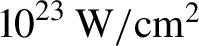
ReLaX is a standalone laser system based on the Pulsar 500 HR product series of Amplitude Technologies France and similar to other Ti:Sa systems[ Reference Schramm, Bussmann, Irman, Siebold, Zeil, Albach, Bernert, Bock, Brack, Branco, Couperus, Cowan, Debus, Eisenmann, Garten, Gebhardt, Grams, Helbig, Huebl, Kluge, Köhler, Krämer, Kraft, Kroll, Kuntzsch, Lehnert, Loeser, Metzkes, Michel, Obst, Pausch, Rehwald, Sauerbrey, Schlenvoigt, Steiniger and Zarini 25 – Reference Kieffer 29 ]. It was delivered and installed in 2018 on site at the EuXFEL (see Figure 1). The optical compressor, beam transport and diagnostic package have been designed and manufactured as contributions to the HiBEF UC by Helmholtz-Zentrum Dresden – Rossendorf (HZDR). The commissioning and integration phase into the HED instrument was successfully finished at the end of 2019.
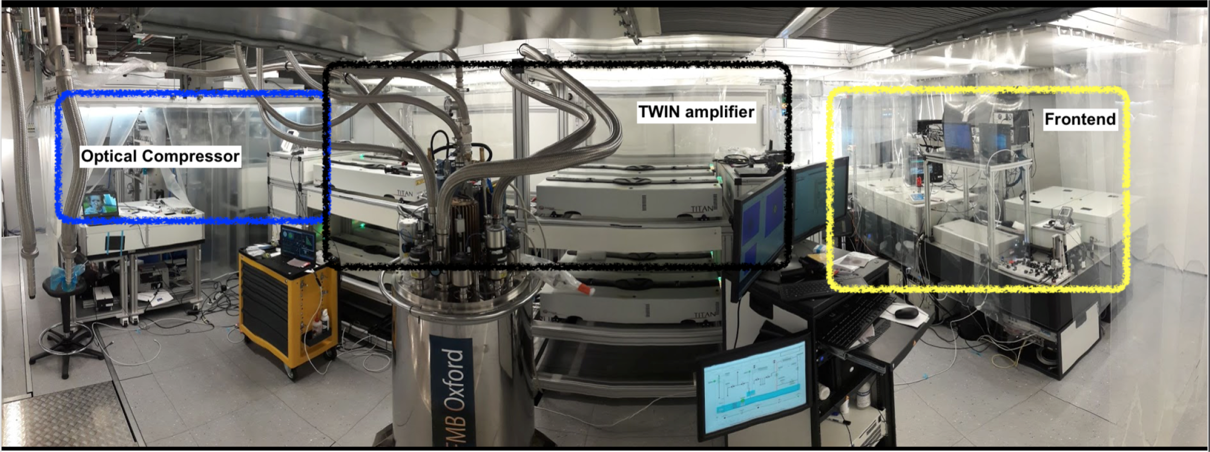
Figure 1 View of the ReLaX laser chain installed in the laser room above the HED hutch; from left to right: optical compressor, TWIN main amplifier with pump-laser blocks and cryo-cooler, front end.
2.1 Laser chain setup
The ReLaX amplification scheme is based on a double chirped pulse amplification (CPA)[ Reference Strickland and Mourou 30 ] system, as shown in Figure 2. As an oscillator, we employ a Spectra Synergy 20 UHP delivering up to 1.2 W of power at an 81.25 MHz repetition rate in 21 fs pulses at a central wavelength of 795 nm. Half of the power is used for seeding the amplification chain. The remaining power is used for providing radio frequency (RF) and optical signals for the optical locking and synchronization units of the oscillator, acousto-optical modulators and timing synchronization system of the laser. Three different timing systems (controlling the pump-laser timings, electro-optical elements and diagnostics) lock onto the RF pulse train of the oscillator; low-frequency dividers of 10 and 5 Hz and single-shot triggers are provided by the EuXFEL timing infrastructure. The fine adjustment of the ReLaX delay compared with the X-ray is done by a digital phase shifter and optically locking the RF pulse train to a 260 MHz timing link measured with a balanced cross-correlation detection scheme[ Reference Schibli, Kim, Kuzucu, Gopinath, Tandon, Petrich, Kolodziejski, Fujimoto, Ippen and Kaertner 31 ]. More results of the synchronization capabilities are shown in Section 2.5.
Figure 2 Setup and amplification scheme of the ReLaX laser chain; the pump lasers are shown in green boxes and the extracted infrared energies are given for maximal configuration.
A first-frequency doubled Nd:YAG laser INLITE II from Continuum is pumping at 10 Hz both CPA1 and also the regenerative amplifier of CPA2. CPA1 consists of the following elements: the oscillator seed is temporally stretched by a bulk glass stretcher and compressed by a transmission grating compressor. It consists of two high-gain multi-pass amplification stages with seven passes each. Between the two stages, a pulse picker Pockels cell reduces the pulse train from 81.25 MHz to 10 Hz and an acousto-optic modulator (DAZZLER 800 HR with low jitter operation option) is used to pre-compensate the spectral phase aberrations. After compression to 42 fs (spectral bandwidth limited), pulses with more than 150 μJ of energy are spatially filtered by a baffle and propagated into a cross-polarized wave (XPW) crystal. This results in an increased bandwidth (as shown in Figure 1) and 90° polarization rotation of the most intense parts of the laser pulse. The temporal intensity contrast is increased by filtering the polarization with six bounces on thin film polarizers, reducing the pulse energy to 30 μJ. The spectral bandwidth is enlarged by the XPW, resulting in a bandwidth corresponding to a Gaussian pulse of 28 fs full width at half maximum (FWHM).
High-temporal-contrast pulses are injected into the CPA2 amplifier chain. An Oeffner-type stretcher is used to temporally lengthen the pulses to 12 ps/nm spectral bandwidth. In addition, a second DAZZLER 800 HR is used to pre-compensate the spectral phase aberration of the whole laser chain. At this point, a few μJ of energy is injected in a regenerative amplifier boosting the energy to mJ level. The REGEN (regenerative amplifier) is built as a ring cavity with a single Pockels cell operated for cavity dumping, injection of the seed and extraction of the amplified pulse after 12 round-trips. An additional second Pockels cell is used to further clean the ns pedestal, resulting in a final amplified spontaneous emission pedestal of 10−11, starting to rise –1 ns in front of the main pulse, and 3×10⁻¹¹ for the –10 ns REGEN pulse replica. An intra-cavity acousto-optic modulator (MAZZLER by Fastlite France) is used to control the spectral bandwidth pre-compensating the gain-narrowing effects of the REGEN. The typical spectral distributions at different amplification stages are shown in Figure 3. Flat-top spectra with 80 nm bandwidth can be compressed to below τ = 25 fs (FWHM) pulse duration, as depicted in Figure 4, as measured by a WIZZLER 800 (Fastlite France). The pulse duration stability has been measured to be ${\sigma}_{\mathrm{tau}}=2.5$
%.
${\sigma}_{\mathrm{tau}}=2.5$
%.

Figure 3 Evolution of the spectral amplitude throughout the amplifier chain.

Figure 4 Spectral amplitude and phase and resulting typical pulse at the end of the amplifier chain.
Two subsequent multi-pass amplifiers, MP1 and MP2, with five passes each increase the pulse energy to 30 and 700 mJ, respectively, with increasing beam size. While MP1 uses a second INLITE II laser with 120 mJ energy, MP2 uses a redundant pumping scheme where two ProPulse+ lasers with up to 2 J energy each are used to pump the MP2 Ti:Sa crystal. A pulse picker Pockels cell (CQX25 from Gooch and Housego, 25 mm hard aperture and 1.1 ns 10%–90% rise time) in combination with a mechanical iris (Uniblitz) is used now to down-select the 10 Hz pulse train to 5 Hz or single-shot operation and block the Pockels cell leakage. The spatial profiles of the pump pulses in MP2 (a total of 2.6 J energy at the crystal) are smoothed out by employing diffracting optical elements, resulting in an amplified flat-top near-field profile. After expansion with a refractive afocal telescope to 6 cm diameter, the beam is injected into the main amplifier.
The main amplifier is built in a TWIN configuration operating with two Ti:Sa crystals of 9 cm diameter. While MP1 and MP2 crystals are water cooled, the TWIN gain medium is cooled down to –180°C by a liquid nitrogen closed-loop cryostat (FMB – Oxford Instruments). The low temperature of the Ti:Sa facilitates the heat removal by increased thermal conductivity and subsequently also minimizes the thermal lens due to radial temperature gradients in the crystal. Up to eight TITAN6 lasers (Amplitude Technologies) with up to 6 J each are used to pump at 5 Hz the TWIN amplifier. In the maximal configuration, 17 J of energy can be extracted from the TWIN using all pump lasers with optimized output parameters. In the nominal configuration employing six pump lasers with conservative output parameters, 10 J can be extracted, and the remaining two pumps are used as spares for redundancy. With an overall transmission efficiency of 60% for the beam transport from the output of the TWIN to the target and assuming 30 fs pulses, 300 TW can be expected to be delivered on target in the maximal configuration, and 200 TW in nominal configuration at shot-on-demand or 5 Hz operation. By temporally interlacing half of the pump lasers (running at 5 Hz) a 100 TW continuous mode at 10 Hz can be generated, if requested by users.
A large aperture Pockels cell (TX7595 from Gooch and Housego, 73.5 mm hard aperture and 5 ns 10%–90% rise time) is used to protect the amplifier chain from back-scattered laser energy, for example, back-scattered radiation from the target located in the focal plane of the final focusing optic. This has been tested to protect from up to 10% back-scattered energy in the nominal configuration. A variable attenuator consisting of a rotating halfwave plate in combination with thin film polarizers in conjunction with the above-mentioned Pockels cell is used to attenuate from 100% to 10% the transmitted energy while conserving the spectral-temporal properties of the main laser pulse (at the expense of degraded temporal contrast). An additional fixed-value reflective attenuator can be used to reduce the energy by 104, allowing one to send an alignment beam to the interaction chamber while operating the amplifiers at nominal output energy. A final reflective afocal telescope magnifies the beam by 2.5 times to a final diameter of approximately 15 cm.
Before injecting the pulses into the optical compressor, the amplified pulses are reflected on an adaptive deformable mirror correcting the spatial phase aberrations for the input of the compressor. A final full beam adaptive deformable mirror with 52 elements (LASQUA, ISP and Phasics) is operated after the compressor to correct the spatial phase for the final focus. Performance of the focal spot quality is shown in Section 2.4.
The main beam optical compressor uses a four-gratings arrangement, with a roof top folding mirror, resulting in two vertically stacked gratings. Low wear of the gold-coated gratings (Plymouth Grating Laboratory 1480 lpm on a low expansion substrate at approximately 53° incidence angle to grating normal) is attained by a fluence of less than 35 mJ/cm2 on the gratings at nominal laser energy. A diagnostic package complements the optical compressor, allowing on shot monitoring of beam pointing or pulse duration and temporal intensity measurements after compression. More details are given in Section 2.3.
It is worth mentioning that a beam-pointing stabilization system consisting of far-field monitors coupled to piezo-driven mirror mounts corrects the injection at various elements of the amplifier chain, such as seed injection into the CPA1 high-gain multi-pass 1, injection into the XPW filter, injection into the CPA2 stretcher and injection into MP1 and MP2 and the TWIN amplifier. Passive far-field and near-field monitors are used throughout the system for additional beam safety and alignment.
2.2 Probe and synchronization beams
We developed three different optical probe beams complementing the main ReLaX beam. After the MP2 amplifier, a polarizer leakage is used to pick up pulses up to 5 mJ of energy. This beam is finally separated into three individual beams: one probe beam can be used for optical imaging in pump-probe experiments at the HED interaction chamber 1 (IC1) (experimental probe beam – ExProbe), the second part is routed to the photon arrival monitor (PAM) device (PAMProbe) approximately 10 m upstream of IC1, which enables one to determine the relative arrival time between the ReLaX and X-ray pulses, and a third beam can be cross-correlated with leakage of the main beam for timing purposes (XProbe) at IC1. The PAM beam requires a different total path length compared with IC1 probes. At first, the probe is separated into two beams that pass a vacuum Herriott Cell (HC), a stable and compact multiple-reflection imaging optical cell for very long optical paths. It comprises three concave mirrors with identical radius of curvature (f = 1 m, two mirrors with 5 cm diameter each, one with 32 cm diameter). Depending on the set angle between these mirrors, the beam makes several reflections in the cell before exiting from it. With one pass we introduce a delay of 26.8 ns with an equivalent of an 8 m beam path length. By increasing the angle one can cover a distance of up to 56 m (13 reflections) or 185.2 ns time delay. This corresponds to a path difference between the main ReLaX beam and the probes at IC1 or PAMProbe. We separate these beams and inject them in a horizontal and a vertical planes in the HC. After the HC, both beams are collimated to a beam diameter of 8 mm and are combined with a spatial separation of 18 mm propagating in parallel until the exit of an air optical compressor. Here, the ExProbe and XProbe are further split. The compressor using 1480 lpm gold gratings is able to compress the beams from a pulse-width (τ p) of sub-ns up to Fourier transform limited (FTL) pulse duration with τ p of ~ 30 fs. In order to avoid high values of the B-integral, the beams are over-compressed by increasing the gratings distance over the FTL point and then individually re-compressed via fused silica (FS) windows as close as possible to their target interaction points. Each probe beam uses a different amount of FS glass optimized to each beam propagation history and, hence, its accumulated dispersion. After the compressor, the optical delay of each probe beam is adjusted using a four-pass folded 50 cm long delay line driven by high-precision piezo actuated linear stages (Smaract SLLA42).
2.3 Online and offline diagnostics package
Careful characterization of the laser properties on target is essential for correctly interpreting data and understanding the outcome of an experiment. Users are provided with both offline and online shot diagnostics information. The offline diagnostics package consists of single-shot temporal pulse diagnostics (SHG cross-correlator, a WIZZLER 800 for the spectrally resolved phase and intensity), a scanning third-order intensity autocorrelator (Sequoia HD) and a spatial phase sensor (SID4) in combination with full beam adaptive deformable mirror closed-loop optimization of the final focus. For the temporal diagnostics, we use a central 1 cm sub-apertured beam at the output of the compressor to perform these diagnostics. A reference trace of the contrast is shown in Figure 5. This measurement has been performed at full MP2 energy level, thus approximately 1 mJ/cm2 fluence, an optimal energy level for the Sequoia HD, minimizing self-phase modulation in the 1 mm exit FS vacuum window. We have performed during the onsite acceptance test of the laser system similar measurements showing that the contrast is preserved while the TWIN is used as the final amplification stage due to the low gain of 10×–20×.

Figure 5 Temporal contrast measured for the main beam sampling the central sub-aperture at full MP2 energy.
The beam transport at full beam aperture is aligned by overlapping cross-hairs placed at different positions throughout the beamline (compressor input and output, in front of each beam-transport folding mirror) using a near-field monitor and crosschecked by a far-field monitor. These near-field and far-field monitors are sampling the leakage of a folding mirror at the output of the compressor (COMP OSP) and the final turning mirror towards IC1 on a dedicated diagnostic table also accommodating the probe beam compressor and delay stages (HIDG). The leakage is imaged by downsizing with telescopes consisting of a 6 m off-axis parabola (OAP) and short focal length lenses adapting to the size of the charge-coupled device (CCD). The near-field and far-field monitors of the final turning mirror towards the interaction chamber are used for the online diagnostic package. A second SID-4 sensor can be used to obtain spatial phase information additional to the near-field intensity monitor. This sensor can be also used for the final adaptive deformable mirror feedback loop or focal spot quality predictions. As part of this diagnostics package, we additionally monitor with a single-shot SHG cross-correlator the pulse duration of the probe beam, and the user can record an energy calorimeter. At the output of the main beam compressor we can switch between p- and s-polarization by routing the beam differently through a periscope. As switching the polarization necessitates a mechanical intervention to the vacuum beam transport and has an impact on the total beam path, and thus the timing of the X-ray arrival, we recommend fixing the polarization for each experiment.
2.4 Experimental capabilities at IC1
The laser beam is routed within IC1 via a set of folding mirrors to an f/2 OAP with 300 mm effective focal length that focuses the beam on the target. IC1 is designed to allow a flexible beam path to the OAP, depending on the irradiation geometries and diagnostics needed for each experiment. Currently, three standard irradiation geometries are defined: co-linear with the X-ray beam; at 45° incidence with respect to the X-ray beam; and at 90° incidence with respect to the X-ray beam (see Figure 6).

Figure 6 Available experimental configurations allowing 0°, 90° and 45°crossing angles between the ReLaX and X-ray beams at IC1.
The laser focus is imaged using the In Line Microscope (ILM) diagnostics, which consist of a Mitutoyo Plan Apo near-infrared (NIR) infinity corrected objective with 20× magnification, routed via a relay-imaging telescope (f 1 = 750 mm, f 2 = 500 mm) to a window port of the interaction chamber where an optical breadboard is attached to the chamber wall. Here, the beam is split into two parts: the transmitted part passes an f = 250 mm lens and images the OAP focal plane onto the focal imaging camera (Basler acA1920-40gm). The reflected part images the plane of the deformable mirror in the compressor onto the SID4 Phasics wavefront sensor in order to perform closed-loop wavefront aberration corrections.
The sample can be characterized using two independent front surface imaging (FSI) systems, one situated at approximately 5° relative to the X-ray beam and one at 90°. Both consist of a 5× infinity corrected Mitutoyu objective, a 200 mm field lens and a 2× magnifying telescope transporting the image onto cameras outside IC1. In order to illuminate the surface of solid foil samples, both FSIs feature fibre-based white light front surface illumination, which can be coupled directly into the beam path via 50/50 beamsplitter cubes. The objective together with the beamsplitter and field lens is mounted on an XYZ stage both for alignment purposes and for retracting the assembly to a parking position during high-power laser shots. The field of view (FoV) is approximately equal to 1 mm and the resolution is approximately equal to 2 μm.
The focal spot quality has been characterized and investigated using the ILM diagnostic and the SID4 sensor. The adaptive mirror was employed to optimize the wavefront at the focus position. The focal spot of 18,500 shots taken at 5 Hz was measured after this optimization, its size was determined per shot and the resulting values were averaged over the total number of shots. This results in FWHM ${}_x=2.47\pm 0.26\kern0.22em \unicode{x3bc} \mathrm{m}$
, FWHM
${}_x=2.47\pm 0.26\kern0.22em \unicode{x3bc} \mathrm{m}$
, FWHM ${}_y=2.64\pm 0.28\kern0.22em \unicode{x3bc} \mathrm{m}$
and a Strehl ratio of 0.65.
${}_y=2.64\pm 0.28\kern0.22em \unicode{x3bc} \mathrm{m}$
and a Strehl ratio of 0.65.
We analysed the stability of the spatial phase with an SID4 wavefront sensor. The calculated distribution of the Strehl ratio over 1000 shots is shown to be 0.69 $\pm$
0.07, with 50% of the shots better than 0.67 and 25% of shots better than 0.72. The results are summarized in Figure 7. For a pulse energy of 3 J on target, a focus size of 2.6 μm at FWHM and a pulse duration of 30 fs, the calculated average intensity on target would reach
$\pm$
0.07, with 50% of the shots better than 0.67 and 25% of shots better than 0.72. The results are summarized in Figure 7. For a pulse energy of 3 J on target, a focus size of 2.6 μm at FWHM and a pulse duration of 30 fs, the calculated average intensity on target would reach $I=3.5\times {10}^{20}\kern0.1em$
W/cm2. For user applications where a larger ReLaX focal spot is desired, we investigated the focus quality by displacing the OAP along the focal direction. For an f/2 parabola, the Rayleigh length is about 25 μm. This result is crosschecked by analysing the intensity within the focal spot and comparing it with the expected intensity profile as a function of the defocusing for a Gaussian beam. This result is shown in Figure 8. At the same time, three examples of the measured focal intensity distribution are shown for best focus, –60 and +60 μm, with respect to the best focus.
$I=3.5\times {10}^{20}\kern0.1em$
W/cm2. For user applications where a larger ReLaX focal spot is desired, we investigated the focus quality by displacing the OAP along the focal direction. For an f/2 parabola, the Rayleigh length is about 25 μm. This result is crosschecked by analysing the intensity within the focal spot and comparing it with the expected intensity profile as a function of the defocusing for a Gaussian beam. This result is shown in Figure 8. At the same time, three examples of the measured focal intensity distribution are shown for best focus, –60 and +60 μm, with respect to the best focus.

Figure 7 (a) Focal spot FWHM evolution. (b) Distribution of the calculated Strehl ratio from wavefront measurements.

Figure 8 Laser focal spot measured with the focal spot diagnostic. A defocus scan is shown as well as the typical far-field for three positions. The colour scale at 0 μm has been reduced by 2.3× compared with the other far-fields for visibility.
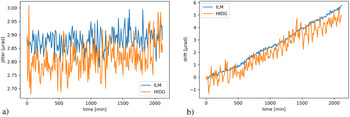
The spatial drift of the beam and its jitter have been measured simultaneously at the focus position via the ILM system, and at the diagnostic table via the HIDG far-field diagnostic, over 40 hours. The drift measured by the ILM is about 5.5 μrad, corresponding to 0.137 μrad/h, or equivalently, 40 nm/h on the focal plane. As shown in Figure 9, the ILM drift correlates with the far-field HIDG drift and can therefore be monitored and compensated. The jitter was averaged over 10-minute slices (Figure 9) in the same time frame. The measured jitter value is approximately equal to 2.8 μrad and it remained stable over the whole period.

Figure 9 (a) Measured jitter RMS by the focal diagnostic in IC1 (ILM) and by the diagnostic table via far-field diagnostic (HIDG) in 10-minute slices. (b) Measured pointing drift by the same diagnostics in 10-minute slices.
2.5 Synchronization and timing capabilities
Synchronization of the optical laser and the X-ray laser with fs precision is an important capability for time-resolved pump-probe experiments performed at XFEL facilities. Generally, the temporal resolution of such experiments is mainly limited by the relative time-of-arrival jitter between the optical laser pulses and the XFEL pulses.
In order to achieve sub-100 fs timing precision, it is not only mandatory to reduce the intrinsic time-of-arrival jitter between ReLaX and the EuXFEL pulses, but also to monitor the residual jitter on a shot-to-shot basis.
The ReLaX seed oscillator is synchronized to the ultrastable low-noise EuXFEL mode-locked master laser oscillator (MLO), which is again phase-locked to the RF master oscillator (MO). All devices across the accelerator and end-stations that require synchronization are connected to the actively length-stabilized optical fibre distribution network. The system allows different synchronization methods, a phase-locked loop (PLL)-type phase-detection scheme at the 16th harmonic (1300 MHz) of the oscillator repetition rate (RF synchronization) and an all-optical lock based on a two-colour balanced optical cross-correlation scheme (optical synchronization)[ Reference Schulz, Grguraš, Behrens, Bromberger, Costello, Czwalinna, Felber, Hoffmann, Ilchen, Liu, Mazza, Meyer, Pfeiffer, Prędki, Schefer, Schmidt, Wegner, Schlarb and Cavalieri 32 , Reference Branlard, Butkowski, Czwalinna, Felber, Kozak, Lamb, Ludwig, Mavric, Müller, Pfeiffer, Ch. Schmidt, Sydlo, Titberize and Schlarb 33 ].
RF synchronization has a typical in-loop jitter of 80 fs root mean square (RMS), while the optical synchronization is capable of sub-10 fs RMS timing jitter. The main advantage of RF synchronization is having no limitation on shifting the delay between optical laser and X-ray arrival. Thus, timing changes can be done up to 100 ps/s. Using optical synchronization, delays are limited to $\pm 2\kern0.1em$
ns and timing changes take 10 times longer. Thus, RF synchronization is ideal for experiments requiring long delay scans, while optical synchronization offers better timing precision.
$\pm 2\kern0.1em$
ns and timing changes take 10 times longer. Thus, RF synchronization is ideal for experiments requiring long delay scans, while optical synchronization offers better timing precision.
In order to preserve the synchronization, two acousto-optical modulators in ReLaX used for spectral dispersion management (DAZZLER 800 HR) have to be operated in the low jitter mode, otherwise inducing an additional 5 fs error each.
The HED end-station at the EuXFEL is equipped with a PAM permanently placed approximately 10 m upstream from IC1, to measure the relative arrival time between the EuXFEL and ReLaX PAMProbe beam. The general idea of the PAM tool is to measure the time-of-arrival on a shot-to-shot basis and use this information to more accurately determine the time-of-arrival at the target position in IC1.
The ReLaX PAMProbe and main beams have a very different beam routing, as described in Section 2.2. This results in potential jitter between these two beams. Therefore, we performed a cross-correlation measurement, investigating the timing jitter at PAM and at IC1 simultaneously. At HED PAM we use as the arrival time diagnostic the spatially encoded transient X-ray induced opacity changes in a 4 μm thick Si3N4 substrate[ Reference Finetti, Höppner, Allaria, Callegari, Capotondi, Cinquegrana, Coreno, Cucini, Danailov, Demidovich, De Ninno, Di Fraia, Feifel, Ferrari, Fröhlich, Gauthier, Golz, Grazioli, Kai, Kurdi, Mahne, Manfredda, Medvedev, Nikolov, Pedersoli, Penco, Plekan, Prandolini, Prince, Raimondi, Rebernik, Riedel, Roussel, Sigalotti, Squibb, Stojanovic, Stranges, Svetina, Tanikawa, Teubner, Tkachenko, Toleikis, Zangrando, Ziaja, Tavella and Giannessi 34 , Reference Kirkwood, Letrun, Tanikawa, Liu, Nakatsutsumi, Emons, Jezynski, Palmer, Lederer, Bean, Buck, di Dio Cafisio, Graceffa, Grünert, Göde, Höppner, Kim, Konopkova, Mills, Makita, Pelka, Preston, Sikorski, Takem, Giewekemeyer, Chollet, Vagovic, Chapman, Mancuso and Sato 35 ]. The Si3N4 target was used at the PAM to maximize the X-ray transmission to 96% at 8 keV photon energy. At IC1 we installed a spatially encoded timing tool using a 20 μm yttrium aluminium garnet (YAG) substrate, used also to find the spatial overlap between the EuXFEL and the ReLaX main beam (full amplification until MP2). We inserted a 150 μm pinhole in the optical path of the main beam before compression to generate a homogeneous flat field illumination in the focal plane of the final focusing optic. The transient signal was filtered by a colour filter in order to suppress the X-ray induced fluorescence of the YAG. The image of the laser beam was recorded with a CCD camera, which is also used for the focus diagnostic. A typical PAM image and the extracted PAM trace are shown in Figure 10(a).

Figure 10 (a) Typical image with absorption edge as measured at the PAM using a 4 μm thick Si3N4 substrate. The white lines indicate the integration area. Lower, the resulting PAM trace (blue) and its first derivative (red) are shown. The minimum of the derivative defines time zero. (b) The correlated results of the measured time-of-arrival timing between PAM and IC1 measurements with N = 2000 shots (3 minutes) and the individual histograms. (c) The measured arrival time traces measured at the PAM and IC1, and the extracted residual difference. The histogram below shows the distribution of the extracted residual difference, which is the temporal jitter between the ReLaX main and ReLaX PAM beams.
We studied the short-term jitter and long-term drifts at the IC1 and PAM positions simultaneously. The PAM supports a timing window of 2 ps with a calibration of 2.35 fs/pixel, while the timing window of IC1 was limited to 300 fs, with a calibration of 0.416 fs/pixel. We measured the relative time-of-arrival of the ReLaX beams with respect to the X-ray at the PAM ${t}_{\mathrm{PAM}}={t}_{\mathrm{PAM}\mathrm{probe}}-{t}_{\mathrm{XFEL}}$
and at IC1
${t}_{\mathrm{PAM}}={t}_{\mathrm{PAM}\mathrm{probe}}-{t}_{\mathrm{XFEL}}$
and at IC1 ${t}_{\mathrm{IC}1}={t}_{\mathrm{Main}}-{t}_{\mathrm{XFEL}}$
. At the PAM, we have determined a relative time-of-arrival jitter of
${t}_{\mathrm{IC}1}={t}_{\mathrm{Main}}-{t}_{\mathrm{XFEL}}$
. At the PAM, we have determined a relative time-of-arrival jitter of ${\sigma}_{\mathrm{PAM}}=24.3$
fs over 3 minutes. The corresponding measured timing jitter at IC1 was
${\sigma}_{\mathrm{PAM}}=24.3$
fs over 3 minutes. The corresponding measured timing jitter at IC1 was ${\sigma}_{\mathrm{IC}1}=26.0$
fs. A long-term measurement over 6 hours indicates a timing drift of approximately 100 fs/h, where a foreseen feedback loop will correct slow drifts in the future.
${\sigma}_{\mathrm{IC}1}=26.0$
fs. A long-term measurement over 6 hours indicates a timing drift of approximately 100 fs/h, where a foreseen feedback loop will correct slow drifts in the future.
In Figure 10(b), the correlation between the PAM and IC1 time-of-arrival jitter is shown and information about the performance of the PAM as an online monitoring tool for experiments is given. The difference of arrival time ${t}_{\mathrm{PAM}\hbox{-} \mathrm{IC}1}={t}_{\mathrm{PAM}\mathrm{probe}}-{t}_{\mathrm{Main}}$
is independent of the XFEL arrival. This relative arrival time has an RMS jitter of
${t}_{\mathrm{PAM}\hbox{-} \mathrm{IC}1}={t}_{\mathrm{PAM}\mathrm{probe}}-{t}_{\mathrm{Main}}$
is independent of the XFEL arrival. This relative arrival time has an RMS jitter of ${\sigma}_{\mathrm{PAM}\hbox{-} \mathrm{IC}1}=12.9$
fs (Figure 10(c)). The differential jitter can be explained by temperature changes, air flow and pressure variations and mechanical vibrations of the different beam transports between the main and PAMProbe beams. In conclusion, using a shot-to-shot timing measurement with the HED PAM tool allows for characterizing the relative time of arrival of the optical laser and X-ray laser at the target with a 12.9 fs RMS accuracy. In experiments where the PAM tool cannot be employed, for example, special X-ray focusing schemes or low X-ray flux, one has to rely on the intrinsic timing jitter between the X-rays and optical laser of 25 fs.
${\sigma}_{\mathrm{PAM}\hbox{-} \mathrm{IC}1}=12.9$
fs (Figure 10(c)). The differential jitter can be explained by temperature changes, air flow and pressure variations and mechanical vibrations of the different beam transports between the main and PAMProbe beams. In conclusion, using a shot-to-shot timing measurement with the HED PAM tool allows for characterizing the relative time of arrival of the optical laser and X-ray laser at the target with a 12.9 fs RMS accuracy. In experiments where the PAM tool cannot be employed, for example, special X-ray focusing schemes or low X-ray flux, one has to rely on the intrinsic timing jitter between the X-rays and optical laser of 25 fs.
3 Experimental commissioning results at the 100 TW level
3.1 Benchmark of laser proton acceleration
The performance of ReLaX as a relativistic plasma driver was investigated. Due to probationary radiation safety permit restrictions, the intensity was limited to a 100 TW level. These restrictions are planned to be lifted in the near future. We have chosen target normal sheath acceleration (TNSA) of protons as a benchmark, since this physical mechanism is well studied in previous experiments (as reviewed by Ref. [Reference Macchi, Borghesi and Passoni36] and references within). TNSA is sensitive to the temporal laser contrast and is dependent on the total laser energy and maximal intensity on the target. The laser was focused on thin solid metal targets and the secondary emitted radiation analysed. The depiction of the experimental setup for these experiments is shown in Figure 6. We tested the polarization switching (see Section 2.3). For this purpose, the incidence angle on the target was 45° in the case of s-polarization and 35° in the case of p-polarization, both with respect to target normal.
A Thomson parabola spectrometer (TPS)[ Reference Zeil, Kraft, Bock, Bussmann, Cowan, Kluge, Metzkes, Richter, Sauerbrey and Schramm 37 ] was used to measure the proton spectrum located approximately 1.3 m downstream centred on the X-ray axis. Ram Ion Meter (Rotem Ind.) radiation detectors were placed outside the chamber to measure the accumulated dose per shot due to the radiation generated. Electromagnetic pulses (EMPs) were measured by two loop antennas inside the chamber. These loop antennas were previously fielded for the Dresden laser acceleration source (DRACO) system at Helmholtz-Zentrum Dresden-Rossendorf (HZDR)[ Reference Consoli, Tikhonchuk, Bardon, Bradford, Carroll, Cikhardt, Cipriani, Clarke, Cowan, Danson, de Angelis, de Marco, Dubois, Etchessahar, Garcia, Hillier, Honsa, Jiang, Kmetik, Krása, Li, Lubrano, McKenna, Metzkes-Ng, Poyé, Prencipe, Raczka, Smith, Vrana, Woolsey, Zemaityte, Zhang, Zhang, Zielbauer and Neely 38 ].
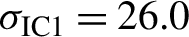
A scan through the focus of the laser was done by displacing the target along the laser axis. The maximum proton energies for different materials, thicknesses and irradiation polarization recorded by the TPS are plotted in Figure 11(a). Maximum proton energies up to 16 MeV for p-polarization and 13 MeV for s-polarization were recorded, indicating the good performance of the laser as a proton beam accelerator via the TNSA mechanism. It is worth mentioning that in the case of the p-polarization, the proton beam was sampled at 10° compared with the target normal. The maximal proton energy in the normal direction is expected to be 10%–20% higher than at this angle[ Reference Nürnberg, Schollmeier, Brambrink, Blasevich, Carroll, Flippo, Gautier, Geißel, Harres, Hegelich, Lundh, Markey, McKenna, Neely, Schreiber and Roth 39 ]. The maximum proton energy recorded peaks at a focus position +25 μm compared with nominal focus. This can be attributed to the uncertainty of the target alignment system, more specifically the FSI depth-of-field. To confirm the alignment of the TPS to the target normal, we have recorded for a few shots the proton beam profiles by a stack of radiochromic films (RCFs) of type EBT3 (Ashland Speciality Ingredients) enveloped by a 30 μm aluminium foil and aligned with a hole on the TPS axis. The first four layers recording signals corresponding to protons of 4.8, 7.4, 9.4 and 11.4 MeV are shown in Figure 11(b). With a maximal proton energy of 16 MeV for p-polarization, ReLaX compares well to previously reported results on laser proton acceleration from thin solid targets[ Reference Zeil, Kraft, Bock, Bussmann, Cowan, Kluge, Metzkes, Richter, Sauerbrey and Schramm 37 ], where a maximal proton cut off energy of 10–20 MeV is typically shown for similar laser and target parameters, validating ReLaX as a successful laser driver.
Figure 11 (a) Maximum proton energies as a function of defocusing distance. (b) RCF raw images of the proton beam. (c) Secondary radiation dose measured by a Ram Ion and integral of the EMP spectrum as a function of focal distance for a 2 μm Ti target.
We also use the measurement from secondary radiation to diagnose the performance of the laser. The integrated EMP spectrum and the dose recorded by the Ram Ion for Ti foil targets with a thickness of 2 μm are plotted in Figure 11(c). The ReLaX polarization was s-polarization in this case. As seen with the proton data, the maximum of the distribution is found at the focus position of +25 μm (after the focus).
3.2 X-ray diagnostics in harsh laser–plasma environments
The secondary radiation generated in the relativistic interaction between the laser and the target poses an enormous challenge for X-ray diagnostics. Giant EMPs with TV/m fields can disrupt the electronics on the detectors[ Reference Consoli, Tikhonchuk, Bardon, Bradford, Carroll, Cikhardt, Cipriani, Clarke, Cowan, Danson, de Angelis, de Marco, Dubois, Etchessahar, Garcia, Hillier, Honsa, Jiang, Kmetik, Krása, Li, Lubrano, McKenna, Metzkes-Ng, Poyé, Prencipe, Raczka, Smith, Vrana, Woolsey, Zemaityte, Zhang, Zhang, Zielbauer and Neely 38 ] and the high energetic electrons[ Reference Daykin, Sawada, Sentoku, Beg, Chen, McLean, Link, Patel and Ping 40 ] and bremsstrahlung photons[ Reference Compant La Fontaine, Courtois, Gobet, Hannachi, Marquès, Tarisien, Versteegen and Bonnet 41 ] can induce backgrounds capable of masking the signal of the physical process under investigation. In the worst case, any of these factors, or a combination of them, can even lead to damage or failure of the detectors. The mitigation of the EMP effects on the detectors as well as the shielding against radiation is an ongoing effort.
We have focused on three main X-ray diagnostics and developed techniques to ensure their function in experiments with ReLaX: small-angle X-ray scattering (SAXS), phase-contrast imaging (PCI) and spectroscopy. In this work, we provide a description of the experimental setup and discuss the shielding strategies used.
3.2.1 Small-angle X-ray scattering
SAXS has been demonstrated as a novel diagnostic to probe the ultrafast dynamics of the interaction between a high-intensity laser and a solid target[ Reference Kluge, Rödel, Metzkes, Pelka, Garcia, Prencipe, Rehwald, Nakatsutsumi, McBride, Schönherr, Garten, Hartley, Zacharias, Erbe, Georgiev, Galtier, Nam, Lee, Glenzer, Bussmann, Gutt, Zeil, Rödel, Hübner, Schramm and Cowan 42 ].
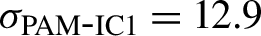
To be able to decouple the direct line of sight (primary unscattered beam) between the detector and the target from the SAXS signal, a special double crystal geometry capable of reflecting the SAXS photons was developed and commissioned[ Reference Šmíd, Baehtz, Pelka, García, Göde, Grenzer, Kluge, Konopkova, Makita, Prencipe, Preston, Rödel and Cowan 43 ]. The reflecting crystals are made of highly annealed pyrolytic graphite (HAPG) with a radius of curvature of 5.5 m. The highest reflectivity corresponds to an X-ray energy of 8.15 keV. The SAXS detector is a Jungfrau module[ Reference Mozzanica, Andrä, Barten, Bergamaschi, Chiriotti, Brückner, Dinapoli, Fröjdh, Greiffenberg, Leonarski, Lopez-Cuenca, Mezza, Redford, Ruder, Schmitt, Shi, Thattil, Tinti, Vetter and Zhang 44 ] with a 512 × 1024 pixel sensitive area and 70 μm pixel size. It was placed outside the chamber approximately 12 cm behind a Kapton vacuum window. The Kapton window is approximately 10 cm off-axis with respect to the XFEL axis, allowing the SAXS photons reflected by the HAPG crystal to go through.
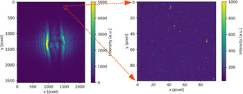
For shielding purposes, the important parameters to know are the detector location and the required signal-to-background ratio. In the case of SAXS, the detector is placed approximately 1.6 m downstream, along the XFEL beam (Figure 12). The detection system must be sensitive to single X-rays at around 8.15 keV.
Geant4[ Reference Agostinelli, Allison, Amako, Apostolakis, Araujo, Arce, Asai, Axen, Banerjee, Barrand, Behner, Bellagamba, Boudreau, Broglia, Brunengo, Burkhardt, Chauvie, Chuma, Chytracek, Cooperman, Cosmo, Degtyarenko, Dell'Acqua, Depaola, Dietrich, Enami, Feliciello, Ferguson, Fesefeldt, Folger, Foppiano, Forti, Garelli, Giani, Giannitrapani, Gibin, Gómez Cadenas, González, Gracia Abril, Greeniaus, Greiner, Grichine, Grossheim, Guatelli, Gumplinger, Hamatsu, Hashimoto, Hasui, Heikkinen, Howard, Ivanchenko, Johnson, Jones, Kallenbach, Kanaya, Kawabata, Kawabata, Kawaguti, Kelner, Kent, Kimura, Kodama, Kokoulin, Kossov, Kurashige, Lamanna, Lampén, Lara, Lefebure, Lei, Liendl, Lockman, Longo, Magni, Maire, Medernach, Minamimoto, Mora de Freitas, Morita, Murakami, Nagamatu, Nartallo, Nieminen, Nishimura, Ohtsubo, Okamura, O'Neale, Oohata, Paech, Perl, Pfeiffer, Pia, Ranjard, Rybin, Sadilov, Di Salvo, Santin, Sasaki, Savvas, Sawada, Scherer, Sei, Sirotenko, Smith, Starkov, Stoecker, Sulkimo, Takahata, Tanaka, Tcherniaev, Safai Tehrani, Tropeano, Truscott, Uno, Urban, Urban, Verderi, Walkden, Wander, Weber, Wellisch, Wenaus, Williams, Wright, Yamada, Yoshida and Zschiesche 45 ] simulations were used to study the background radiation generated in the laser plasma interaction and their effect on the SAXS detector. The chamber geometry and the SAXS setup were implemented. The primary particle spectrum was electrons with an exponential energy dependence. The temperature for this distribution was calculated according to scaling laws[ Reference Kluge, Cowan, Debus, Schramm, Zeil and Bussmann 46 ] and set to 2 MeV. The electrons were impinging on the target at 45° analogue to the irradiation geometry with ReLaX. The target was a copper foil with a thickness of 10 μm. Without any shielding, the energy deposited per pixel on average was several MeV. This is three orders of magnitude higher than the energy deposited by a single 8.15 keV photon.
Figure 12 Schematic depiction of a pump-probe experiment with ReLaX and XFEL and the associated diagnostics.
A design for an in-vacuum lead wall was proposed. The wall comprises 10 cm × 10 cm × 5 cm blocks of lead encased in 2 mm of steel to provide high-vacuum compatibility. The total dimensions of the wall are 60 cm in length (perpendicular to the XFEL beam), 30 cm in height and 10 cm in thickness. The wall has a hole with a diameter of 3 cm to allow the XFEL and SAXS signal to go through. As an indication, 10 cm of lead will effectively stop all photons with energies below 100 keV, and transmit 0.01% of photons with energies of 1 MeV. The expected background signal on the detector with this shielding was estimated at a few hundred keV.
The effect of the in-vacuum lead wall was investigated by shooting the ReLaX laser at 100 TW intensity on 2-μm thick titanium foil targets. The SAXS detector was displaced downstream and sideways with respect to the Kapton window in such a way that the HAPG reflection remained on the SAXS Jungfrau. Therefore, the only parameter changed was the shadowing of the SAXS Jungfrau by the in-vacuum lead wall. The energy deposition due to secondary radiation was recorded for each of the positions. The results can be seen in Figure 13. With the detector closest to the Kapton window, the detector is also closest to the XFEL beam axis and, thus, it has a direct line of sight to the target. In this case, the effect of the lead wall is minimal, resulting in an energy deposition in the MeV range. By moving the detector as specified before, the shielding of the lead wall becomes apparent, resulting in an average energy deposition per pixel of approximately equal to 250 keV (equivalent to 31 X-ray photons at 8.15 keV).

Figure 13 Energy deposit per pixel in the SAXS Jungfrau as a function of the distance to the flange.
As a proof-of-concept, a copper wire with a diameter of 10 μm was pumped with ReLaX. The XFEL beam was delayed 1 ps after the optical beam to probe the generated plasma. The recorded signal is shown in Figure 14. The signature of the X-ray scattering on the wire appears as a straight line at an angle of –45º with respect to the horizontal axis. This streak can be seen reflected by the crystal, on both sides of the gap, analogue to the scattering on the edge. A lineout representing the average intensity per pixel can be seen in the lower left panel.

Figure 14 Upper panel: SAXS signal recorded by the Jungfrau detector. The red squares show the areas where the SAXS signal and the backgrounds were averaged. In the lower right panel, the energy deposition per pixel due to secondary radiation is plotted. In the lower left, the lineout of the SAXS signal and the corresponding background levels are shown.
There are two main contributions to the background recorded by the detector. Secondary radiation will leak through the collimator hole in the in-vacuum lead wall and scatter in any element located afterwards (flanges, chamber walls, the HAPG crystal support). This is observed in the background recorded outside of the crystal projection. Furthermore, the crystal itself not only reflects the XFEL scattered photons, but all the photons generated at the interaction point that fulfil the Bragg condition, that is, photons with energies E = m×8.15 keV. The bremsstrahlung spectrum covers the whole range of energies, and therefore the bremsstrahlung photons are also reflected by the HAPG crystal. This is seen in the increase of energy deposition per pixel on the HAPG crystal projection.
3.2.2 Phase-contrast imaging
PCI has been successfully applied at XFEL beamlines in recent years in a variety of experiments[ Reference Schropp, Hoppe, Meier, Patommel, Seiboth, Lee, Nagler, Galtier, Arnold, Zastrau, Hastings, Nilsson, Uhlén, Vogt, Hertz and Schroer 47 – Reference Hagemann, Hagemann, Vassholz, Hoeppe, Osterhoff, Rosselló, Mettin, Seiboth, Schropp, Möller, Hallmann, Kim, Scholz, Boesenberg, Schaffer, Zozulya, Lu, Shayduk, Madsen, Schroer and Salditt 49 ]. The ability to probe the electron density state within the target with femtosecond time scales has great potential when used to probe the physical interaction of the short-pulse laser with the target. We have developed the technique to be employed in conjunction with SAXS in relativistic plasmas.
The PCI detector is an imaging system built by Optique Peter. It consists of a scintillator (in our case 20 μm thick YAG) imaged via a 10× Mitutoyo objective, which is optically coupled to an Andor Zyla CMOS camera. The setup is placed on the detector bench, which in our case was 5.2 m downstream from the target to provide sufficient magnification. The magnification of such a system can be quantified as M=(L+d)/d, where L is the distance from the target to the detector and d is the XFEL focus to the target distance. For our application, the X-ray focus was 30 cm before the target, giving M $\approx$
18.
$\approx$
18.
One advantage of the PCI detection system compared with the SAXS in terms of bremsstrahlung background is the distance. The SAXS detector was located approximately 1.6 m downstream from target chamber center (TCC), while the PCI is 5.2 m. A simple assumption of a dependency of the bremsstrahlung flux as $1/{d}^2$
indicates a reduction of bremsstrahlung flux by a factor 20. Furthermore, PCI is measured using the full XFEL beam, exploiting a number of X-ray photons, and is of the order of 1012; therefore, the final signal-to-background ratio is improved not only by reduced backgrounds but also by a larger signal. Design estimates showed S/B=107, and therefore no special shielding was designed for this case.
$1/{d}^2$
indicates a reduction of bremsstrahlung flux by a factor 20. Furthermore, PCI is measured using the full XFEL beam, exploiting a number of X-ray photons, and is of the order of 1012; therefore, the final signal-to-background ratio is improved not only by reduced backgrounds but also by a larger signal. Design estimates showed S/B=107, and therefore no special shielding was designed for this case.
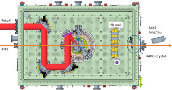
The experimental measurement of PCI for the same Cu wire shot as SAXS is shown in Figure 15. The wire is oriented in the vertical direction. Due to the high coherence of the XFEL beam, strong diffraction fringes appear. However, the detailed analysis of this image is outside the scope of this paper. In terms of background, the design estimates are confirmed. The hits due to bremsstrahlung appear as single pixels salt-and-pepper noise.

Figure 15 Left panel: PCI raw data of a 10 μm Cu wire while pumped by ReLaX. Right panel: expanded section of 100 × 100 pixels showing the salt-and-pepper noise.
3.2.3 X-ray spectroscopy
X-ray spectrometers are an integral part of the HED instrument. They are commissioned by using the XFEL beam[ Reference Preston, Göde, Schwinkendorf, Appel, Brambrink, Cerantola, Höppner, Makita, Pelka, Prescher, Sukharnikov, Schmidt, Thorpe, Toncian, Amouretti, Chekrygina, Falcone, Falk, Fletcher, Galtier, Harmand, Hartley, Hau-Riege, Heimann, Huang, Humphries, Karnbach, Kraus, Lee, Nagler, Ren, Schuster, Smid, Voigt, Zhang and Zastrau 50 ]. The challenge in a laser environment is multifold: on one hand, the detector must be shielded against the EMPs generated in the laser–target interaction; on the other hand, the detector must be also shielded against the secondary radiation flooding the interior of the vacuum chamber.
As a first step in the shielding development, we fielded an X-ray spectrometer (BSPEC) in a backward geometry. It consists of an HAPG crystal in von Hámos geometry aligned to reflect the Kα emission from copper targets onto a Jungfrau detector. The energy range covered from 7.9 to 8.8 keV with a resolution of about 2 eV. The detector was placed upstream from the target position facing the front surface. The energy of the bremsstrahlung background is expected to be lower in this geometry as compared with the SAXS geometry. Anisotropy in the bremsstrahlung emission from the target has been previously reported[ Reference McKeever, Makita, Nersisyan, Dzelzainis, White, Kettle, Dromey, Zepf, Sarri, Doria, Ahmed, Lewis, Riley and Robinson 51 ].
The first tests of this detector in the laser environment showed a large background (10s of MeV per pixel) in some shots. For the majority of high-power laser shots (75%), the detector failed to record an image with negative values. This happened only during the laser shot; the detector could recover and record a valid image at the next trigger. The assumption for the reason for this failure was a high flux of low energetic bremsstrahlung (<100 keV). To reduce this flux, an aluminium line-of-sight blocker was developed. It consists of an aluminium blocker with a thickness of 1 cm placed over the HAPG crystal. With this blocker in place, the failure rate was decreased down to less than 1%.
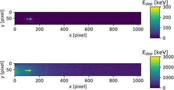
The results of this system are shown in Figure 16. Firstly, the BSPEC was aligned by pumping the Cu target with the XFEL beam at a photon energy of 9.7 keV (above the Cu K-edge). The beam was unfocused with an FoV on the target of a few hundred μm. The pulse energy was about 0.7 mJ. The upper panel shows the recorded signal by the Jungfrau detector for a single X-ray pulse. Afterwards, a Cu wire with a diameter of 10 μm was pumped by ReLaX. The optical laser was focused on the target with best focus ( $\approx 2.7\kern0.22em \unicode{x3bc} \mathrm{m}$
) with a pulse energy of 3 J. The XFEL beam was used to probe the target, as explained in the SAXS and PCI sections. The X-ray photon energy was 8.15 keV, with an FoV on the target of approximately equal to 30 μm and a pulse energy of 3 mJ. Since the X-ray energy was lower than the K-edge, there will not be any Kα emission caused by it. The lower panel of Figure 16 shows the emission from the hot target. A lineout of both cases is shown in Figure 17. There the signal was normalized to the total integral for each case, and the results were plotted. The X-ray-only shot shows a signal-to-background ratio of almost three orders of magnitude, while the ReLaX shot shows a signal-to-background ratio lower than one order of magnitude. From this result, we conclude that while the detector is no longer saturated due to bremsstrahlung in the low keV regime, further improvement of the signal quality can be achieved via shielding optimization.
$\approx 2.7\kern0.22em \unicode{x3bc} \mathrm{m}$
) with a pulse energy of 3 J. The XFEL beam was used to probe the target, as explained in the SAXS and PCI sections. The X-ray photon energy was 8.15 keV, with an FoV on the target of approximately equal to 30 μm and a pulse energy of 3 mJ. Since the X-ray energy was lower than the K-edge, there will not be any Kα emission caused by it. The lower panel of Figure 16 shows the emission from the hot target. A lineout of both cases is shown in Figure 17. There the signal was normalized to the total integral for each case, and the results were plotted. The X-ray-only shot shows a signal-to-background ratio of almost three orders of magnitude, while the ReLaX shot shows a signal-to-background ratio lower than one order of magnitude. From this result, we conclude that while the detector is no longer saturated due to bremsstrahlung in the low keV regime, further improvement of the signal quality can be achieved via shielding optimization.

Figure 16 X-ray signal recorded by the backwards X-ray spectrometer. Upper panel: Cu Kα emission when pumped by the XFEL beam at 9.7 keV. Lower panel: Cu Kα emission when pumped by ReLaX.

Figure 17 Normalized intensity of the recorded X-ray spectra.
4 Summary
We have successfully demonstrated the integration and operation of a 100-TW class laser on samples combined with an XFEL beam. A particular development is the quality of optical synchronization with 25 fs RMS jitter, or the capability to measure on a single-shot basis the arrival time of the main beam by 13 fs precision, both numbers increasing the precision by an order of magnitude compared with previous facilities. We have successfully used a laser proton acceleration experiment as base for a benchmark to validate the expected properties of the laser on the target. We have investigated the effect of EMP and laser generated secondary radiation and particle sources on several X-ray diagnostics, and have developed successful strategies to reduce their impacts.
Acknowledgements
The authors thank J. Hauser, A. Schmidt, I. Thorpe, K. Sukharnikov and A. Berghäuser for the expert mechanical and electronic integration support; the DESY MSK group for the expert support on timing and synchronization; I. Prencipe for manufacturing and mounting of targets; M. Lederer for the continued support. The authors also thank their colleagues from HED at the EuXFEL and FWKH, FWKT and FWF at HZDR for their support. A.-M. Talposi was supported by the German Academic Exchange Service (DAAD) through a short-term Doctoral Research Grant. We acknowledge the European XFEL in Schenefeld, Germany, for provision of X-Ray FEL beamtime at the Scientific Instrument HED and would like to thank the staff for their assistance. The authors are indebted to the HiBEF user consortium for the provision of instrumentation and staff that enabled this experiment.


 Open access