

1. Introduction
In this decade, active research has been carried out on the laser plasma acceleration concept[Reference Tajima and Dawson1] in order to achieve high-energy, high-quality electron beams with GeV energy in a cm-scale plasma[Reference Leemans, Nagler, Gonsalves, Toth, Nakamura, Geddes, Esarey, Schroeder and Hooker2–Reference Kim, Pae, Cha, Kim, Yu, Sung, Lee, Jeong and Lee6], 1%-level energy spread[Reference Kameshima, Hong, Sugiyama, Wen, Wu, Tang, Zhu, Gu, Zhang, Peng, Kurokawa, Chen, Tajima, Kumita and Nakajima7], 1-mm-mrad-level transverse emittance[Reference Karsch, Osterhoff, Popp, Rowlands-Rees, Major, Fuchs, Marx, Hörlein, Schmid, Veisz, Becker, Schramm, Hidding, Pretzler, Habs, Grüner, Krausz and Hooker8] and 1-fs-level bunch duration[Reference Lundh, Lim, Rechatin, Ammoura, Ben-Ismail, Davoine, Gallot, Goddet, Lefebvre, Malka and Faure9], ensuring that the stability of reproduction is as high as that of present high-power ultrashort-pulse lasers[Reference Hafz, Jeong, Choi, Lee, Pae, Kulagin, Sung, Yu, Hong, Hosokai, Cary, Ko and Lee10]. Recently, staged laser plasma acceleration[Reference Liu, Xia, Wang, Lu, Wang, Deng, Li, Zhang, Liang, Leng, Lu, Wang, Wang, Nakajima, Li and Xu11, Reference Pollock, Clayton, Ralph, Albert, Davidson, Divol, Filip, Glenzer, Herpoldt, Lu, Marsh, Meinecke, Mori, Pak, Rensink, Ross, Shaw, Tynan, Joshi and Froula12] has been successfully demonstrated in conjunction with ionization-induced injection[Reference Pak, Marsh, Martins, Lu, Mori and Joshi13–Reference Xia, Liu, Wang, Lu, Cheng, Deng, Li, Zhang, Liang, Leng, Lu, Wang, Wang, Nakajima, Li and Xu15]. Based on recent results on laser plasma acceleration experiments and large-scale particle-in-cell (PIC) simulations[Reference Martins, Fonseca, Lu, Mori and Silva16–Reference Tzoufras, Huang, Cooley, Tsung, Vieira and Mori18], design consideration and feasibility studies on applications for high-energy frontier colliders with TeV-range center-of-mass energy have been carried out[Reference Schroeder, Esarey, Geddes, Benedetti and Leemans19, Reference Nakajima, Deng, Zhang, Shen, Liu, Li, Xu, Ostermayr, Petrovics, Klier, Iqbal, Ruhl and Tajima20]. In this context, state-of-the-art PW-class lasers allow us to study the feasibility of laser plasma accelerators toward the 10–100-GeV range in a full-scale experiment. For example, a large-scale experiment[Reference Nakajima, Lu, Zhao, Shen, Li and Xu21] is proposed to implement the demonstration of 100-GeV electron beam acceleration by means of a laser plasma accelerator driven with a multi-PW laser capable of delivering 3.5-kJ, 500-fs pulses[Reference Blanchot, Bar, Behar, Bellet, Bigourd, Boubault, Chappuis, Coïc, Damiens-Dupont, Flour, Hartmann, Hilsz, Hugonnot, Lavastre, Luce, Mazataud, Neauport, Noailles, Remy, Sautarel, Sautet and Rouyer22]. This capability allows us to explore laser plasma acceleration operated in the entire laser wakefield regime, from the linear regime to the nonlinear bubble regime. Such a large-scale laser plasma accelerator may comprise a gas jet or a short gas cell, which acts as an injector, followed by a long, uniform, low-density plasma or preformed plasma channel (plasma waveguide) that acts as an accelerating medium. In order to implement this project, we need to strongly corroborate design formulas that scale experimental results properly.
We organize the remainder of this paper as follows. Section 2 presents an overview of progress and recent achievements in laser plasma electron acceleration. Section 3 considers the energy scaling of laser wakefield acceleration for the self-guided and channel-guided cases in both the quasi-linear and the nonlinear bubble regimes as well as the comparison of such scaling formulas with recent experimental results on multi-GeV electron acceleration. Section 4 presents the design formulas and examples of 10-GeV-level laser wakefield accelerators as well as a comparison with the result from a three-dimensional full-scale PIC simulation[Reference Martins, Fonseca, Lu, Mori and Silva16].
2. Overview of laser plasma electron acceleration
Laser-driven plasma-based accelerators have evolved from a groundbreaking concept by Tajima and Dawson[Reference Tajima and Dawson1] into the reality of next-generation particle accelerator technologies. Relativistic electron beams from ultraintense laser plasma interactions can be conceived to be compact particle accelerators, inspiring a wide range of applications of unique particle beam and radiation sources such as THz[Reference Leemans, Geddes, Faure, Tóth, van Tilborg, Schroeder, Esarey and Fubiani23] and betatron x-ray radiation[Reference Kneip, McGuffey, Martins, Martins, Bellei, Chvykov, Dollar, Fonseca, Huntington, Kalintchenko, Maksimchuk, Mangles, Matsuoka, Nagel, Palmer, Schreiber, Ta Phuoc, Thomas, Yanovsky, Silva, Krushelnick and Najmudin24]. Furthermore, it is envisaged that laser plasma accelerators will downsize large-scale particle accelerators such as x-ray free-electron lasers[Reference Nakajima, Kando, Kawakubo, Nakanishi and Ogata25–Reference Nakajima, Deng, Yoshitama, Hafz, Lu, Shen, Liu, Li and Xu28] and high-energy frontier colliders[Reference Schroeder, Esarey, Geddes, Benedetti and Leemans19, Reference Nakajima, Deng, Zhang, Shen, Liu, Li, Xu, Ostermayr, Petrovics, Klier, Iqbal, Ruhl and Tajima20] to a realistic extent in both dimensions and costs.
In fact, there has been significant experimental progress in laser wakefield acceleration of electron beams since the incipient experiments on laser wakefield accelerators successfully demonstrated ultrahigh gradient acceleration of the order of  $100~\text{GeVm}^{-1}$, using chirped pulse amplification lasers with 10-TW class peak power and 1 ps pulse duration[Reference Nakajima, Fisher, Kawakubo, Nakanishi, Ogata, Kato, Kitagawa, Kodama, Mima, Shiraga, Suzuki, Yamakawa, Zhang, Sakawa, Shoji, Nishida, Yugami, Downer and Tajima29, Reference Modena, Najmudin, Dangor, Clayton, Marsh, Joshi, Malka, Darrow, Danson, Neely and Walsh30]. Such experiments are characterized in terms of the self-modulated wakefield regime[Reference Andreev, Gorbunov, Kirsanov, Pogosova and Ramazashvili31], where the laser power should be higher than the critical power for relativistic self-focusing and the laser pulse duration is longer than the plasma period. In this regime, the laser pulse undergoes temporal intensity modulation and self-guiding through nonlinear interactions with the plasma, so that large-amplitude plasma waves are resonantly excited. Ultimately, wave breakings occur, generating relativistic electrons to be randomly trapped and accelerated by wakefields throughout the acceleration distance. Therefore, electron beams produced from single-stage experiments showed energy spectra with 100% energy spread, as characterized by a Maxwellian distribution with the highest energy tail reaching at most 100 MeV[Reference Najmudin, Krushelnick, Clark, Mangles, Walton, Dangor, Fritzler, Malka, Lefebvre, Gordon, Tsung and Joshi32]. The energy gain of accelerated electrons should be determined by the acceleration distance, which is restricted due to dephasing of electrons with respect to the correct acceleration phase of the wakefield and due to depletion of the laser pulse energy. For most experiments using a supersonic gas jet, the acceleration distance extends only to a few mm, so that the energy gain is limited to the order of 200 MeV[Reference Malka, Fritzler, Lefebvre, Aleonard, Burgy, Chambaret, Chemin, Krushelnick, Malka, Mangles, Najmudin, Pittman, Rousseau, Scheurer, Walton and Dangor33].
For many practical applications of electron beams, quality, stability and controllability of the beam performance such as energy, energy spread, emittance and charge are indispensable in addition to compact and robust features of accelerators. In this context, breakthrough experiments[Reference Mangles, Murphy, Najmudin, Thomas, Collier, Dangor, Divall, Foster, Gallacher, Hooker, Jaroszynski, Langley, Mori, Norreys, Tsung, Viskup, Walton and Krushelnick34–Reference Faure, Glinec, Pukhov, Kiselev, Gordienko, Lefebvre, Rousseau, Burgy and Malka36] have succeeded in producing high-quality electron beams, so-called quasi-monoenergetic beams, with ultrashort pulses, small energy spread and low emittance. Quasi-monoenergetic electron beams have been obtained from the use of ultrashort laser pulses with durations of the order of several tens of femtoseconds and by controlling the plasma density precisely to make the dephasing length long enough to exceed the acceleration distance. Under these conditions, once the plasma electrons expelled by the ponderomotive force (radiation pressure) of the laser pulse form a plasma cavity called a ‘bubble’, then some of them are self-injected into the wakefield by a wave-breaking or restoring force exerted by an ion channel remaining unshielded behind the laser pulse. As a result of beam loading of trapped electrons, the nonlinear wakefield amplitude inside the bubble is reduced below the trapping threshold. Consequently, electrons trapped in the wakefield undergo the processes of acceleration and bunching toward the wave crest to increase their energy and brightness unless the acceleration distance exceeds the dephasing length. This is a scenario of quasi-monoenergetic electron beam acceleration, based on the self-injection mechanism in the bubble regime, which is visually shown by multi-dimensional PIC simulations[Reference Kostyukov, Pukhov and Kiselev37, Reference Lu, Tzoufras, Joshi, Tsung, Mori, Vieira, Fonseca and Silva38].
Although self-injection is a robust method relying on self-focusing, self-compression of the laser pulse and expansion of the bubble[Reference Kalmykov, Yi, Khudik and Shvets39] which occur during the propagation of relativistic laser pulses, initially heated (accelerated) electrons with large transverse momentum are injected into nonlinear wakefields that excite betatron oscillation of accelerated electrons due to the strong focusing field. Hence, if the self-injection and the deterioration of beam quality are suppressed, high-quality electron beams can be produced by controlled injection schemes such as colliding optical injection[Reference Faure, Rechatin, Norlin, Lifschitz, Glinec and Malka40, Reference Kotaki, Daito, Kando, Hayashi, Kawase, Kameshima, Fukuda, Homma, Ma, Chen, Esirkepov, Pirozhkov, Koga, Faenov, Pikuz, Kiriyama, Okada, Shimomura, Nakai, Tanoue, Sasao, Wakai, Matsuura, Kondo, Kanazawa, Sugiyama, Daido and Bulanov41], density-transition injection[Reference Schmid, Buck, Sears, Mikhailova, Tautz, Herrmann, Geissler, Krausz and Veisz42] or density down-ramp[Reference Gonsalves, Nakamura, Lin, Panasenko, Shiraishi, Sokollik, Benedetti, Schroeder, Geddes, van Tilborg, Osterhoff, Esarey, Toth and Leemans43] and ionization-induced injection[Reference Pak, Marsh, Martins, Lu, Mori and Joshi13–Reference Xia, Liu, Wang, Lu, Cheng, Deng, Li, Zhang, Liang, Leng, Lu, Wang, Wang, Nakajima, Li and Xu15] in the quasi-linear regime of wakefields driven by a laser pulse with a moderate intensity. These injection schemes provide us with high-quality electron beam injectors for the front end of multi-stage high-energy accelerators. As a simplest case, two-stage laser plasma acceleration has been successfully demonstrated in combination with ionization-induced injection[Reference Liu, Xia, Wang, Lu, Wang, Deng, Li, Zhang, Liang, Leng, Lu, Wang, Wang, Nakajima, Li and Xu11, Reference Pollock, Clayton, Ralph, Albert, Davidson, Divol, Filip, Glenzer, Herpoldt, Lu, Marsh, Meinecke, Mori, Pak, Rensink, Ross, Shaw, Tynan, Joshi and Froula12].
For laser plasma acceleration reaching GeV-level energies, it is essential to propagate intense laser pulses over a centimeter-scale distance in underdense plasma. For this purpose, a preformed plasma density channel with a parabolic radial distribution[Reference Ehrlich, Cohen, Zigler, Krall, Sprangle and Esarey44] has been developed for guiding a laser beam over many Rayleigh lengths without diffraction which limits the acceleration distance to a few mm in a uniform plasma. Plasma density channels stabilize the propagation of relativistically intense laser pulses under a matched condition, preventing laser plasma nonlinear instabilities, such as filamentation and hosing which often occur in self-guiding[Reference Naumova, Koga, Nakajima, Tajima, Esirkepov, Bulanov and Pegoraro45, Reference Chen, Kotaki, Nakajima, Koga, Bulanov, Tajima, Gu, Peng, Wang, Wen, Liu, Jiao, Zhang, Huang, Guo, Zhou, Hua, An, Tang and Lin46]. Therefore, the concept of channel-guided laser wakefield accelerators has been a long-standing proposal[Reference Hubbard, Kaganovich, Hafizi, Moore, Sprangle, Ting and Zigler47]. Employing a centimeter-scale plasma waveguide, experiments on GeV-level electron acceleration have been carried out with a gas-filled or ablative discharge capillary[Reference Leemans, Nagler, Gonsalves, Toth, Nakamura, Geddes, Esarey, Schroeder and Hooker2, Reference Kameshima, Hong, Sugiyama, Wen, Wu, Tang, Zhu, Gu, Zhang, Peng, Kurokawa, Chen, Tajima, Kumita and Nakajima7, Reference Karsch, Osterhoff, Popp, Rowlands-Rees, Major, Fuchs, Marx, Hörlein, Schmid, Veisz, Becker, Schramm, Hidding, Pretzler, Habs, Grüner, Krausz and Hooker8] to demonstrate quasi-monoenergetic electron beams. Experimental progress beyond 1 GeV has been reported in experiments making use of a 100-TW class laser and a centimeter-scale capillary discharge plasma waveguide[Reference Lu, Liu, Wang, Wang, Liu, Deng, Xu, Xia, Li, Zhang, Lu, Wang, Wang, Liang, Leng, Shen, Nakajima, Li and Xu4] or a gas cell relying on self-guiding[Reference Clayton, Ralph, Albert, Fonseca, Glenzer, Joshi, Lu, Marsh, Martins, Mori, Pak, Tsung, Pollock, Ross, Silva and Froula3]. During the last two decades, a number of laser plasma accelerator experiments have been carried out under various conditions. Comparing these data with theoretical laser wakefield acceleration models, it may be useful to find a correct scaling law capable of predicting energy gain, accelerated electron charge and the required laser and plasma conditions.
3. Energy scaling of laser wakefield acceleration in the relativistic regime
3.1. Propagation of relativistic laser pulses in plasma
The wave equation for the normalized vector potential describing the evolution of a laser pulse with laser wavelength  ${\it\lambda}_{L}$ and duration
  ${\it\tau}_{L}$ (full width at half maximum, FWHM) in a plasma channel can be written as[Reference Hafizi, Ting, Sprangle and Hubbard48]
 $$\begin{eqnarray}\left({\rm\nabla}^{2}-\frac{\partial ^{2}}{c^{2}\partial t^{2}}\right)\mathbf{a}=k^{2}\left(1-{\it\eta}^{2}\right)\mathbf{a},\end{eqnarray}$$
 where  $\mathbf{a}\equiv e\mathbf{A}/m_{e}c^{2}$ is the vector potential
  $\mathbf{A}$ of the laser pulse normalized with respect to the electron rest energy
  $m_{e}c^{2}$, satisfying the Coulomb gauge
  ${\rm\nabla}\boldsymbol{\cdot }\mathbf{a}=0$, and
  $k={\it\omega}/c=2{\it\pi}/{\it\lambda}_{L}$ is the free-space wavenumber along the propagation direction. The (squared) refractive index for linearly polarized electromagnetic waves in the long-pulse limit (
 $ck_{p}{\it\tau}_{L}\gg 1$) is given by[Reference Hafizi, Ting, Hubbard, Sprangle and Penano49]
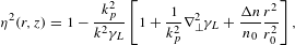 $$\begin{eqnarray}{\it\eta}^{2}(r,z)=1-\frac{k_{p}^{2}}{k^{2}{\it\gamma}_{L}}\left[1+\frac{1}{k_{p}^{2}}{\rm\nabla}_{\bot }^{2}{\it\gamma}_{L}+\frac{{\rm\Delta}n}{n_{0}}\frac{r^{2}}{r_{0}^{2}}\right],\end{eqnarray}$$
 where  $k_{p}={\it\omega}_{p}/c=(4{\it\pi}r_{e}n_{0})^{1/2}$ is the plasma wavenumber evaluated with the unperturbed on-axis density
  $n_{0}$ and the classical electron radius
  $r_{e}=e^{2}/mc^{2}$, and
  ${\it\gamma}_{L}=(1+a^{2}/2)^{1/2}$ is the relativistic factor of the laser intensity for linear polarization. In Equation (2), the first term represents free-space propagation, and the three terms in the square brackets correspond to relativistic self-focusing, ponderomotive channeling and a preformed plasma channel with a parabolic density distribution of the form
  $n(r)=n_{0}[1+({\rm\Delta}n/n_{0})(r^{2}/r_{L}^{2})]$, where
  $r_{L}$ is the laser spot radius and
  ${\rm\Delta}n$ is the channel depth. Analysis of the wave equation with the standard paraxial form provides the matched spot radius
  $r_{m}$ under the condition of a beam propagating with a constant spot size
  $r_{L}$, i.e.,
  $k_{p}r_{m}=k_{p}r_{L}=R_{m}$, given by[Reference Nakajima, Lu, Zhao, Shen, Li and Xu21]
 $$\begin{eqnarray}\displaystyle k_{p}^{2}r_{m}^{2} & \equiv & \displaystyle R_{m}^{2}(a_{0}^{2},{\rm\Delta}n/n_{0})\nonumber\\ \displaystyle & = & \displaystyle 2\ln ({\it\gamma}_{L0})\{\!{\it\gamma}_{L0}-1{-}2\ln ((1+{\it\gamma}_{L0})/2)\nonumber\\ \displaystyle & & \displaystyle +\,({\rm\Delta}n/n_{0})[\!1-{\it\gamma}_{L0}+\ln ((1+{\it\gamma}_{L0})/2)\nonumber\\ \displaystyle & & \displaystyle +\,(a_{0}^{2}/4)\,_{4}F_{3}(1/2,1,1,1;2,2,2;-a_{0}^{2}/2)\!]\!\}\!^{-1},\quad\end{eqnarray}$$
 where  ${\it\gamma}_{L0}=(1+a_{0}^{2}/2)^{1/2}$ is the relativistic factor for a Gaussian laser beam with peak amplitude
  $a_{0}$ and
  $_{p}F_{q}$ denotes the generalized hypergeometric series of order
  $q$ and class
  $q-p+1$.
Under the matched condition that no phase shift of the laser pulse occurs, the group velocity is written as  ${\it\beta}_{g}^{2}\approx 1-k_{p}^{2}/({\it\kappa}_{\text{ch}}k^{2})$, where a correction factor for the group velocity is defined as[Reference Nakajima, Lu, Zhao, Shen, Li and Xu21]
 $$\begin{eqnarray}\displaystyle & & \displaystyle {\it\kappa}_{\text{ch}}(a_{0}^{2},{\rm\Delta}n/n_{0})=\frac{a_{0}^{2}}{8} [\!{\it\gamma}_{L0}-1-\ln ((1+{\it\gamma}_{L0})/2)\nonumber\\ \displaystyle & & \displaystyle \quad +\,\frac{a_{0}^{2}}{8}\frac{{\rm\Delta}n}{n_{0}}_{4}F_{3}(1/2,1,1,1;2,2,2;-a_{0}^{2}/2)\!]\,\!^{-1}.\end{eqnarray}$$
 Under the matched condition for self-guiding, the spot radius and the group velocity correction factor are given by Equations (3) and (4), respectively, where the channel depth is set to be  ${\rm\Delta}n=0$.
3.2. Laser plasma acceleration in the quasi-linear regime
In the linear laser wakefield with the accelerating field  $E_{z}=E_{z0}\cos {\rm\Psi}$, the equations of the longitudinal motion of an electron with the normalized velocity
  ${\it\beta}_{z}=v_{z}/c\approx 1$ and electron energy
  ${\it\gamma}=E_{e}/m_{e}c^{2}$ are given by[Reference Chiu, Cheshkov and Tajima50]
 $$\begin{eqnarray}\displaystyle \begin{array}{@{}c@{}}\displaystyle \frac{d{\it\gamma}}{dz}=k_{p}\frac{E_{z0}}{E_{0}}\cos {\rm\Psi}\quad \text{and}\\ \displaystyle \frac{d{\rm\Psi}}{dz}=k_{p}\left(1-\frac{{\it\beta}_{p}}{{\it\beta}_{z}}\right)\approx \frac{k_{p}}{2{\it\gamma}_{g}^{2}},\end{array} & & \displaystyle\end{eqnarray}$$
 where  ${\rm\Psi}=k_{p}(z-v_{p}t)+{\rm\Psi}_{0}$ is the phase of the plasma wave,
  $E_{0}=mc{\it\omega}_{p}/e$ is the non-relativistic wave-breaking field approximately given by
  $E_{0}\approx 96~[\text{GV m}^{-1}]$
  $(n_{e}/10^{18}~[\text{cm}^{-3}])^{1/2}$,
  ${\it\beta}_{p}=v_{p}/c\approx v_{g}/c={\it\beta}_{g}$ is the phase velocity
  $v_{p}$ of the plasma wave normalized to
  $c$, and
  ${\it\gamma}_{g}=(1-{\it\beta}_{g}^{2})^{-1/2}\gg 1$ is assumed. By integrating Equations (5), the energy and phase of the electron can be calculated as
 $$\begin{eqnarray}\displaystyle \begin{array}{@{}c@{}}\displaystyle {\it\gamma}(z)={\it\gamma}_{0}+2{\it\gamma}_{g}^{2}\frac{E_{z0}}{E_{0}}[\sin {\rm\Psi}(z)-\sin {\rm\Psi}_{0}]\quad \text{and}\quad \\ \displaystyle {\rm\Psi}(z)\approx \frac{k_{p}z}{2{\it\gamma}_{g}^{2}}+{\rm\Psi}_{0}.\end{array} & & \displaystyle\end{eqnarray}$$
 Setting the initial electron phase  ${\rm\Psi}_{0}=0$ at
  $z=0$, the maximum energy gain is given by
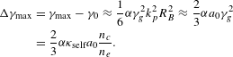
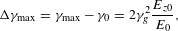 $$\begin{eqnarray}{\rm\Delta}{\it\gamma}_{\max }={\it\gamma}_{\max }-{\it\gamma}_{0}=2{\it\gamma}_{g}^{2}\frac{E_{z0}}{E_{0}},\end{eqnarray}$$
 at  $k_{p}z={\it\pi}{\it\gamma}_{g}^{2}$ or
  $z={\it\lambda}_{p}{\it\gamma}_{g}^{2}/2$. As shown from Equations (6), setting
  ${\rm\Psi}_{0}=-{\it\pi}/2$, the maximum energy gain reaches
 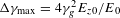 ${\rm\Delta}{\it\gamma}_{\max }=4{\it\gamma}_{g}^{2}E_{z0}/E_{0}$ at
  $k_{p}z=2{\it\pi}{\it\gamma}_{g}^{2}$ or
  $z={\it\lambda}_{p}{\it\gamma}_{g}^{2}$. However, electrons undergo both acceleration and focusing only for the phase
  $0\leqslant {\rm\Psi}\leqslant {\it\pi}/2$. Hence, we define the dephasing length as
  $L_{\text{dp}}={\it\lambda}_{p}{\it\gamma}_{g}^{2}/2$. Considering a driving laser pulse of normalized intensity
  $a_{0}^{2}$ moving in a plasma channel with channel depth
  ${\rm\Delta}n$ at the group velocity
  ${\it\beta}_{g}=v_{g}/c$ with the corresponding relativistic factor
  ${\it\gamma}_{g}^{2}=(1-{\it\beta}_{g}^{2})^{-1}\approx {\it\kappa}_{\text{ch}}({\it\omega}^{2}/{\it\omega}_{p}^{2})={\it\kappa}_{\text{ch}}(n_{c}/n_{e})={\it\kappa}_{\text{ch}}{\it\gamma}_{g0}^{2}$, where
  ${\it\gamma}_{g0}={\it\omega}/{\it\omega}_{p}$ is the relativistic factor for the group velocity in a uniform plasma and its correction factor
  ${\it\kappa}_{\text{ch}}$ is given by Equation (4), the maximum energy gain and the dephasing length are written as
 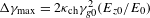 ${\rm\Delta}{\it\gamma}_{\max }=2{\it\kappa}_{\text{ch}}{\it\gamma}_{g0}^{2}(E_{z0}/E_{0})$ and
 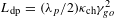 $L_{\text{dp}}=({\it\lambda}_{p}/2){\it\kappa}_{\text{ch}}{\it\gamma}_{go}^{2}$, respectively. In the limit of
  $a_{0}^{2}\ll 1$,
 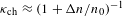 ${\it\kappa}_{\text{ch}}\approx (1+{\rm\Delta}n/n_{0})^{-1}$. In the quasi-linear regime, taking the beam loading effect into account, the maximum accelerating field driven by a Gaussian laser pulse is given by[Reference Nakajima, Deng, Zhang, Shen, Liu, Li, Xu, Ostermayr, Petrovics, Klier, Iqbal, Ruhl and Tajima20]
 $$\begin{eqnarray}\frac{E_{z0}}{E_{0}}\simeq \sqrt{{\it\pi}}{\it\alpha}a_{0}^{2}\left(\frac{k_{p}{\it\sigma}_{L}}{4}\right)\exp \left(-\frac{k_{p}^{2}{\it\sigma}_{L}^{2}}{4}\right)\approx 0.38{\it\alpha}a_{0}^{2},\end{eqnarray}$$
 where  ${\it\alpha}$ denotes a factor of accelerating field reduction due to the beam loading effect and
  ${\it\sigma}_{L}$ is the rms pulse length of the Gaussian temporal profile with the FWHM length
  $c{\it\tau}_{L}\sim 0.375{\it\lambda}_{p}$ for
  $k_{p}{\it\sigma}_{L}=\sqrt{2}$.
3.3. Laser plasma acceleration in the bubble regime
Previous laser plasma acceleration experiments that successfully demonstrated the production of quasi-monoenergetic electron beams with narrow energy spread have been elucidated in terms of self-injection and an acceleration mechanism in the bubble regime[Reference Kostyukov, Pukhov and Kiselev37, Reference Lu, Tzoufras, Joshi, Tsung, Mori, Vieira, Fonseca and Silva38]. In these experiments, electrons are self-injected into a nonlinear wake, often referred to as a bubble, i.e., a cavity void of plasma electrons consisting of a spherical ion column surrounded by a narrow electron sheath, formed behind the laser pulse instead of a periodic plasma wave in the linear regime. The phenomenological theory of a nonlinear wakefield in the bubble regime describes the accelerating wakefield  $E_{z}({\it\xi})/E_{0}\approx (1/2)k_{p}{\it\xi}$ in the bubble frame moving in the plasma with velocity
  $v_{B}$, i.e.,
  ${\it\xi}=z-v_{B}t$. In the bubble (blowout) regime for
  $a_{0}\geqslant 2$, since the electron-evacuated cavity shape is determined by balancing the Lorentz force of the ion sphere exerted on the electron sheath with the ponderomotive force of the laser pulse, the bubble radius
  $R_{B}$ is approximately given as
  $k_{p}R_{B}\approx 2\sqrt{a_{0}}$ (Ref. [Reference Lu, Tzoufras, Joshi, Tsung, Mori, Vieira, Fonseca and Silva38]). Thus, the maximum accelerating field is obtained as
  $E_{z0}/E_{0}=(1/2){\it\alpha}k_{p}R_{B}$, where
  ${\it\alpha}$ represents a factor that takes into account the difference between the simulation and theoretical estimation, and more significantly the accelerating field reduction due to the beam loading effects.
In self-guided laser wakefield acceleration, where a driving laser pulse propagates by means of self-channeling, the equations of longitudinal motion of an electron are approximately written as[Reference Nakajima, Lu, Zhao, Shen, Li and Xu21]
 $$\begin{eqnarray}\displaystyle \begin{array}{@{}l@{}}\displaystyle \frac{d{\it\gamma}}{dz}=k_{p}\frac{E_{z0}}{E_{0}}\left(1-\frac{{\it\xi}}{R_{B}}\right)=\frac{1}{2}{\it\alpha}k_{p}^{2}R_{B}\left(1-\frac{{\it\xi}}{R_{B}}\right)\\ \text{and}\quad \displaystyle \frac{d{\it\xi}}{dz}=1-\frac{{\it\beta}_{B}}{{\it\beta}_{z}}\approx 1-{\it\beta}_{B}\approx \frac{3}{2{\it\gamma}_{g}^{2}},\end{array} & & \displaystyle\end{eqnarray}$$
 where  ${\it\xi}=z-v_{B}t\,(0\leqslant {\it\xi}\leqslant R_{B})$ is the longitudinal coordinate of the bubble frame moving at the velocity
  $v_{B}=c{\it\beta}_{B}\approx v_{g}-v_{\text{etch}}$ and taking into account the diffraction at the laser front that etches back at the velocity
  $v_{\text{etch}}\simeq c({\it\omega}_{p}/{\it\omega})^{2}$ (Ref. [Reference Lu, Tzoufras, Joshi, Tsung, Mori, Vieira, Fonseca and Silva38]). Integrating Equations (5), the energy and phase of the electron can be calculated as
 $$\begin{eqnarray}\displaystyle \begin{array}{@{}l@{}}\displaystyle {\it\gamma}(z)={\it\gamma}_{0}+\frac{1}{3}{\it\alpha}{\it\gamma}_{g}^{2}k_{p}^{2}R_{B}{\it\xi}(z)\left(1-\frac{1}{2}\frac{{\it\xi}(z)}{R_{B}}\right)\\ \text{and}\quad \displaystyle {\it\xi}(z)=\frac{3}{2}\frac{z}{{\it\gamma}_{g}^{2}},\end{array} & & \displaystyle\end{eqnarray}$$
 where  ${\it\gamma}_{0}={\it\gamma}(0)$ is the injection energy. Hence, the maximum energy gain is obtained at
  ${\it\xi}=R_{B}$ as
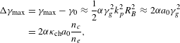
 $$\begin{eqnarray}\displaystyle {\rm\Delta}{\it\gamma}_{\max } & = & \displaystyle {\it\gamma}_{\max }-{\it\gamma}_{0}\approx \frac{1}{6}{\it\alpha}{\it\gamma}_{g}^{2}k_{p}^{2}R_{B}^{2}\approx \frac{2}{3}{\it\alpha}a_{0}{\it\gamma}_{g}^{2}\nonumber\\ \displaystyle & = & \displaystyle \frac{2}{3}{\it\alpha}{\it\kappa}_{\text{self}}a_{0}\frac{n_{c}}{n_{e}}.\end{eqnarray}$$
 The dephasing length  $L_{\text{dp}}$ for the self-guided bubble regime is given by
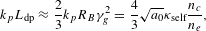 $$\begin{eqnarray}k_{p}L_{\text{dp}}\approx \frac{2}{3}k_{p}R_{B}{\it\gamma}_{g}^{2}=\frac{4}{3}\sqrt{a_{0}}{\it\kappa}_{\text{self}}\frac{n_{c}}{n_{e}},\end{eqnarray}$$
i.e.,
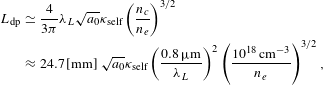 $$\begin{eqnarray}\displaystyle L_{\text{dp}} & \simeq & \displaystyle \frac{4}{3{\it\pi}}{\it\lambda}_{L}\sqrt{a_{0}}{\it\kappa}_{\text{self}}\left(\frac{n_{c}}{n_{e}}\right)^{3/2}\nonumber\\ \displaystyle & {\approx} & \displaystyle 24.7\,[\text{mm}]~\sqrt{a_{0}}{\it\kappa}_{\text{self}}\left(\frac{0.8\,{\rm\mu}\text{m}}{{\it\lambda}_{L}}\right)^{2}\left(\frac{10^{18}\,\text{cm}^{-3}}{n_{e}}\right)^{3/2},\nonumber\\ \displaystyle & & \displaystyle\end{eqnarray}$$
while the pump depletion length due to pulse-front erosion is given by
 $$\begin{eqnarray}L_{\text{pd}}\approx c{\it\tau}_{L}\frac{n_{c}}{n_{e}},\end{eqnarray}$$
 where  ${\it\kappa}_{\text{self}}\equiv {\it\kappa}_{\text{ch}}(a_{0}^{2},0)$ is the correction factor of the group velocity for the self-guided pulse in Equation (4).
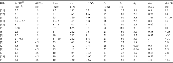
Table 1. Parameters of experiments on GeV-class laser wakefield acceleration.
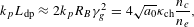
For a driving laser pulse propagating in a plasma channel, the equations of electron motion are given by setting  $v_{B}=c{\it\beta}_{B}\approx v_{g}$ in Equations (5), i.e.,
 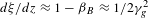 $d{\it\xi}/dz\approx 1-{\it\beta}_{B}\approx 1/2{\it\gamma}_{g}^{2}$. Hence, the maximum energy gain is
 $$\begin{eqnarray}\displaystyle {\rm\Delta}{\it\gamma}_{\max } & = & \displaystyle {\it\gamma}_{\max }-{\it\gamma}_{0}\approx \frac{1}{2}{\it\alpha}{\it\gamma}_{g}^{2}k_{p}^{2}R_{B}^{2}\approx 2{\it\alpha}a_{0}{\it\gamma}_{g}^{2}\nonumber\\ \displaystyle & = & \displaystyle 2{\it\alpha}{\it\kappa}_{\text{ch}}a_{0}\frac{n_{c}}{n_{e}},\end{eqnarray}$$
 and the dephasing length  $L_{\text{dp}}$ is
 $$\begin{eqnarray}k_{p}L_{\text{dp}}\approx 2k_{p}R_{B}{\it\gamma}_{g}^{2}=4\sqrt{a_{0}}{\it\kappa}_{\text{ch}}\frac{n_{c}}{n_{e}},\end{eqnarray}$$
 where  ${\it\kappa}_{\text{ch}}$ is given by Equation (4). For channel-guided laser plasma acceleration, the pump depletion length, at which the total field energy becomes half of the initial laser energy, is given by
 $$\begin{eqnarray}L_{\text{pd}}\approx \frac{\sqrt{{\it\pi}}}{2{\it\alpha}^{2}}a_{0}{\it\sigma}_{L}\frac{n_{c}}{n_{e}}=\frac{1}{4}\sqrt{\frac{{\it\pi}}{\ln 2}}\frac{a_{0}c{\it\tau}_{L}}{{\it\alpha}^{2}}\frac{n_{c}}{n_{e}},\end{eqnarray}$$
 where  ${\it\sigma}_{L}=c{\it\tau}_{L}/(2\sqrt{\ln 2})\approx 0.6c{\it\tau}_{L}$ is the rms pulse length.
The matched power  $P_{m}$ corresponding to the matched spot size
  $r_{L}$ is calculated as
 $$\begin{eqnarray}P_{L}=\frac{k_{p}^{2}r_{L}^{2}a_{0}^{2}}{32}P_{c},\end{eqnarray}$$
 where 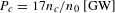 $P_{c}=17n_{c}/n_{0}\;[\text{GW}]$ is the critical power for the relativistic self-focusing at the plasma density
  $n_{0}$ and the required pulse energy is
  $U_{L}=P_{L}{\it\tau}_{L}$.
3.4. Beam loading effects
In laser wakefield acceleration, an accelerated electron beam induces its own wakefield and cancels the laser-driven wakefield. Assuming the beam loading efficiency  ${\it\eta}_{b}\equiv 1-E_{z}^{2}/E_{M}^{2}$ defined by the fraction of the plasma wave energy absorbed by particles of the bunch with the rms radius
  ${\it\sigma}_{b}$, the beam-loaded field is given by
  $E_{z}=\sqrt{1-{\it\eta}_{b}}E_{M}={\it\alpha}E_{M}$, where
  $E_{M}$ is the accelerating field without beam loading, given by
  $E_{M}\approx a_{0}^{1/2}E_{0}$ for the bubble regime
  $a_{0}\geqslant 2$. Thus, the loaded charge is calculated as[Reference Nakajima, Deng, Zhang, Shen, Liu, Li, Xu, Ostermayr, Petrovics, Klier, Iqbal, Ruhl and Tajima20]
 $$\begin{eqnarray}\displaystyle Q_{b} & \simeq & \displaystyle \frac{e}{4k_{L}r_{e}}\frac{{\it\eta}_{b}k_{p}^{2}{\it\sigma}_{b}^{2}}{1-{\it\eta}_{b}}\frac{E_{z}}{E_{0}}\left(\frac{n_{c}}{n_{e}}\right)^{1/2}\nonumber\\ \displaystyle & {\approx} & \displaystyle 76\left[\text{pC}\right]\!\frac{(1-{\it\alpha}^{2})a_{0}^{1/2}k_{p}^{2}{\it\sigma}_{b}^{2}}{{\it\alpha}}\!\left(\frac{n_{e}}{10^{18}\,\text{cm}^{-3}}\!\right)\!^{-1/2}.\quad\end{eqnarray}$$
 Here, the field reduction factor  ${\it\alpha}$ for accelerating charge
  $Q_{b}$ in the operating plasma density
  $n_{e}$ is obtained by solving the equation
 $$\begin{eqnarray}{\it\alpha}^{2}+B{\it\alpha}-1=0,\end{eqnarray}$$
 where the coefficient  $B$ is defined as
 $$\begin{eqnarray}B\equiv \frac{1}{a_{0}^{1/2}k_{p}^{2}{\it\sigma}_{b}^{2}}\left(\frac{Q_{b}}{\text{76 pC}}\right)\left(\frac{n_{e}}{10^{18}\,\text{cm}^{-3}}\right)^{1/2}.\end{eqnarray}$$
Thus, the field reduction factor is obtained by
 $$\begin{eqnarray}{\it\alpha}=\frac{B}{2}\left[\left(1+\frac{4}{B^{2}}\right)^{1/2}-1\right].\end{eqnarray}$$
 For  $B\ll 1$, the field reduction factor becomes
  ${\it\alpha}\approx 1$ and contrarily, for
  $B\gg 1$,
  ${\it\alpha}\approx 0$.
3.5. Comparison with experimental results on GeV-class electron beams
Table 1 summarizes the parameters for experiments on laser wakefield acceleration driven by a self-guided laser pulse with channel depth  ${\rm\Delta}n/n_{e}=0$ (Refs. [Reference Clayton, Ralph, Albert, Fonseca, Glenzer, Joshi, Lu, Marsh, Martins, Mori, Pak, Tsung, Pollock, Ross, Silva and Froula3, Reference Wang, Zgadzaj, Fazel, Li, Yi, Zhang, Henderson, Chang, Korzekwa, Tsai, Pai, Quevedo, Dyer, Gaul, Martinez, Bernstein, Borger, Spinks, Donovan, Khudik, Shvets, Ditmire and Downer5, Reference Kim, Pae, Cha, Kim, Yu, Sung, Lee, Jeong and Lee6, Reference Liu, Xia, Wang, Lu, Wang, Deng, Li, Zhang, Liang, Leng, Lu, Wang, Wang, Nakajima, Li and Xu11, Reference Pollock, Clayton, Ralph, Albert, Davidson, Divol, Filip, Glenzer, Herpoldt, Lu, Marsh, Meinecke, Mori, Pak, Rensink, Ross, Shaw, Tynan, Joshi and Froula12, Reference Kneip, Nagel, Martins, Mangles, Bellei, Chekhlov, Clarke, Delerue, Divall, Doucas, Ertel, Fiuza, Fonseca, Foster, Hawkes, Hooker, Krushelnick, Mori, Palmer, Ta Phuoc, Rajeev, Schreiber, Streeter, Urner, Vieira, Silva and Najmudin51, Reference Froula, Clayton, Döppner, Marsh, Barty, Divol, Fonseca, Glenzer, Joshi, Lu, Martins, Michel, Mori, Palastro, Pollock, Pak, Ralph, Ross, Siders, Silva and Wang52]) and a channel-guided laser pulse with
  ${\rm\Delta}n/n_{e}\neq 0$ (Refs. [Reference Leemans, Nagler, Gonsalves, Toth, Nakamura, Geddes, Esarey, Schroeder and Hooker2, Reference Lu, Liu, Wang, Wang, Liu, Deng, Xu, Xia, Li, Zhang, Lu, Wang, Wang, Liang, Leng, Shen, Nakajima, Li and Xu4, Reference Kameshima, Hong, Sugiyama, Wen, Wu, Tang, Zhu, Gu, Zhang, Peng, Kurokawa, Chen, Tajima, Kumita and Nakajima7, Reference Karsch, Osterhoff, Popp, Rowlands-Rees, Major, Fuchs, Marx, Hörlein, Schmid, Veisz, Becker, Schramm, Hidding, Pretzler, Habs, Grüner, Krausz and Hooker8, Reference Ibbotson, Bourgeois, Rowlands-Rees, Caballero, Bajlekov, Walker, Kneip, Mangles, Nagel, Palmer, Delerue, Doucas, Urner, Chekhlov, Clarke, Divall, Ertel, Foster, Hawkes, Hooker, Parry, Rajeev, Streeter and Hooker53]). Since the maximum energy gain scales as
  ${\rm\Delta}{\it\gamma}_{\max }\propto n_{c}\propto {\it\lambda}_{L}^{-2}$ for a given
  $a_{0}$, most previous experiments have employed chirped pulse amplification lasers with wavelength
  ${\it\lambda}_{L}=800\,\text{nm}$ and pulse duration
  ${\it\tau}_{L}\leqslant 80\,\text{fs}$, except for the case of Ref. [Reference Wang, Zgadzaj, Fazel, Li, Yi, Zhang, Henderson, Chang, Korzekwa, Tsai, Pai, Quevedo, Dyer, Gaul, Martinez, Bernstein, Borger, Spinks, Donovan, Khudik, Shvets, Ditmire and Downer5], where a PW-class laser with wavelength
  ${\it\lambda}_{L}=1057\,\text{nm}$ and
  ${\it\tau}_{L}\sim 150\,\text{fs}$ was employed. The validity of the energy scaling formulas (Equations (7), (11) and (15)) based on the present analytical methods may be verified by comparison with these experimental results. Figure 1 shows the comparison of measured electron beam energies in laser wakefield acceleration with the energy scaling on the operating plasma density for the self-guided case (Figure 1(a)) in the bubble regime and the channel-guided case (Figure 1(b)) in both the quasi-linear regime and the bubble regime. In the energy scaling formulas, we assume that the field reduction due to beam loading and the group velocity correction due to relativistic effects cancel each other out, i.e.,
  ${\it\alpha}{\it\kappa}_{\text{self}}\sim 1$ or
  ${\it\alpha}{\it\kappa}_{\text{ch}}\sim 1$.
For self-guided laser wakefield acceleration, the multi-GeV acceleration results reported in Refs. [Reference Wang, Zgadzaj, Fazel, Li, Yi, Zhang, Henderson, Chang, Korzekwa, Tsai, Pai, Quevedo, Dyer, Gaul, Martinez, Bernstein, Borger, Spinks, Donovan, Khudik, Shvets, Ditmire and Downer5, Reference Kim, Pae, Cha, Kim, Yu, Sung, Lee, Jeong and Lee6] provide us with informative examples for testing the energy scaling formula (Equation (11)). In Ref. [Reference Wang, Zgadzaj, Fazel, Li, Yi, Zhang, Henderson, Chang, Korzekwa, Tsai, Pai, Quevedo, Dyer, Gaul, Martinez, Bernstein, Borger, Spinks, Donovan, Khudik, Shvets, Ditmire and Downer5], a 625-TW, 160-fs laser pulse with wavelength  ${\it\lambda}_{L}=1057\,\text{nm}$ is focused onto a
  $1/e^{2}$ spot radius of
  $r_{L}=50\,{\rm\mu}\text{m}$, producing
  $a_{0}=3.6$ at the entrance of a 7-cm long gas cell with
  $n_{e}=4.8\times 10^{17}\,\text{cm}^{-3}$. The accelerated electron beam has a quasi-monoenergetic peak at 2.0 GeV with a relative energy spread of 10% (FWHM), containing a total charge of 540 pC in a bunch. In this case, from Equations (3) and (4), the dimensionless matched spot radius
  $R_{m}=k_{p}r_{m}$ and the correction factor of the group velocity
  ${\it\kappa}_{\text{self}}={\it\kappa}_{\text{ch}}(a_{0}^{2},0)$ are
  $R_{m}=2.0$ and
  ${\it\kappa}_{\text{self}}=1.46$, respectively, at
  $a_{0}=3.6$. Thus, since the matched spot radius is
  $r_{m}=15\,{\rm\mu}\text{m}$, the laser pulse undergoes self-focusing after propagating through the gas cell. Using Equations (20) and (21) and assuming the electron beam size
  $k_{p}{\it\sigma}_{b}=1$, the field reduction factor
  ${\it\alpha}$ is calculated as
  ${\it\alpha}\approx 0.32$ (
 $B\approx 2.84$). From Equation (13), the dephasing length is
  $L_{\text{dp}}\approx 118\,\text{mm}$, while from Equation (14), the pump depletion length due to pulse-front erosion is
  $L_{\text{pd}}\approx 100\,\text{mm}$. From Equation (10), the electron beam energy at the accelerator length
  $z=L_{\text{acc}}$ is estimated as
 $$\begin{eqnarray}\displaystyle E_{b}(L_{\text{acc}}) & = & \displaystyle E_{b0}+m_{e}c^{2}{\it\alpha}\sqrt{a_{0}}k_{p}L_{\text{acc}}\left(1-\frac{L_{\text{acc}}}{2L_{\text{dp}}}\right)\nonumber\\ \displaystyle & {\approx} & \displaystyle E_{b0}+96\,[\text{MeV}]\,{\it\alpha}\sqrt{a_{0}}\left(1-\frac{L_{\text{acc}}}{2L_{\text{dp}}}\right)\nonumber\\ \displaystyle & & \displaystyle \times \,\left(\frac{L_{\text{acc}}}{1\,\text{mm}}\right)\left(\frac{n_{e}}{10^{18}\,\text{cm}^{-3}}\right)^{1/2},\end{eqnarray}$$
 where  $E_{b0}$ is the injection beam energy. For
  $L_{\text{acc}}=70\,\text{mm}$, the beam energy is evaluated to be
  $E_{b}=2.0\;\text{GeV}$. This estimate is in good agreement with the measured beam energy of
  $2.0\pm 0.1~\text{GeV}$[Reference Wang, Zgadzaj, Fazel, Li, Yi, Zhang, Henderson, Chang, Korzekwa, Tsai, Pai, Quevedo, Dyer, Gaul, Martinez, Bernstein, Borger, Spinks, Donovan, Khudik, Shvets, Ditmire and Downer5], taking into account the field reduction factor
  ${\it\alpha}$ due to beam loading.
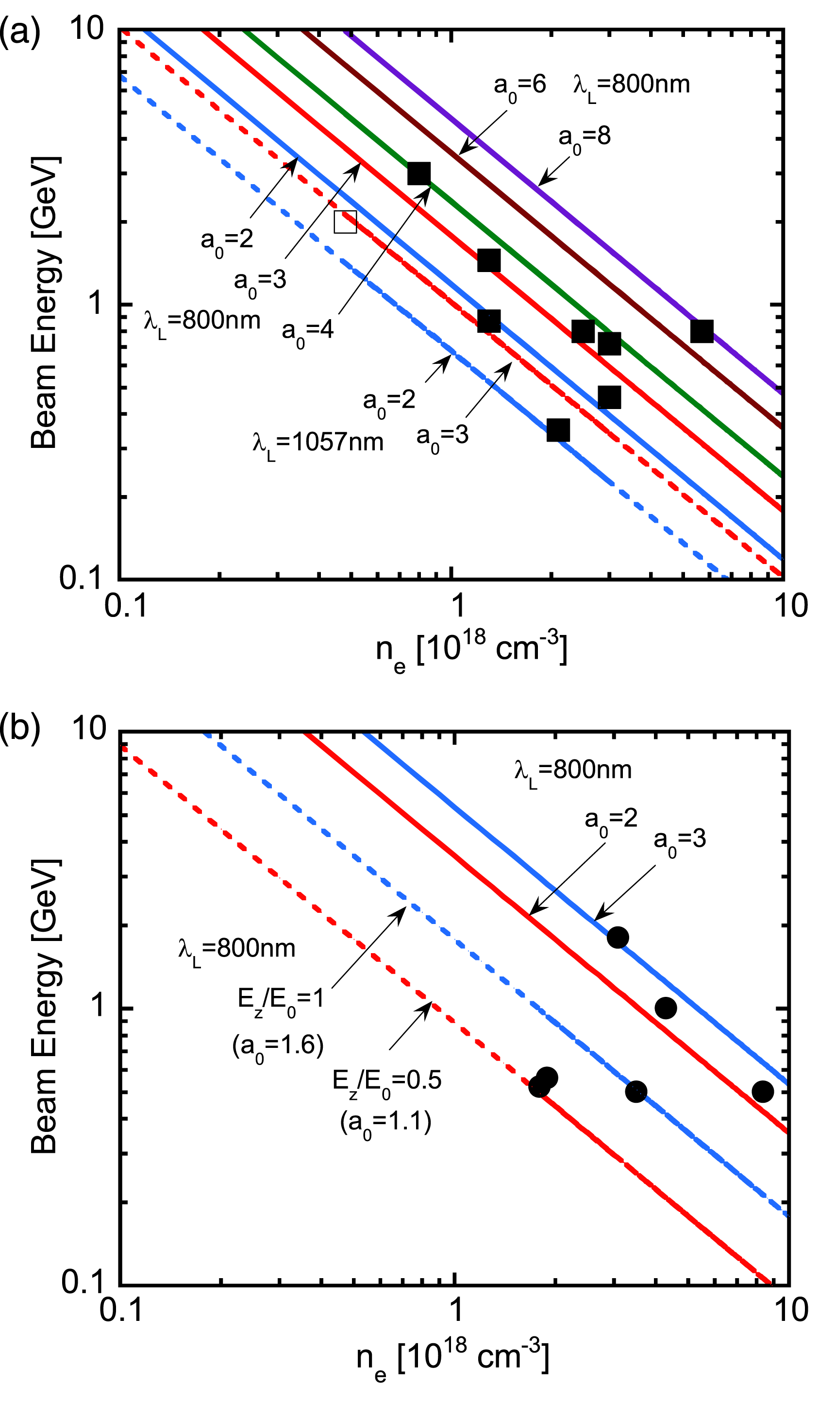
Figure 1. A comparison of measured electron beam energies in laser wakefield acceleration with the energy scaling as a function of the operating plasma density for (a) the self-guided case in the bubble regime at laser wavelengths of 800 nm (solid line) and 1057 nm (dashed line) and (b) the channel-guided case in both the quasi-linear regime (dashed line) and the bubble regime (solid line). The experimental data are plotted with filled squares for  ${\it\lambda}_{L}=800\,\text{nm}$ and the open square for
  ${\it\lambda}_{L}=1057\,\text{nm}$ in (a), and with filled circles for
  ${\it\lambda}_{L}=800\,\text{nm}$ in (b).
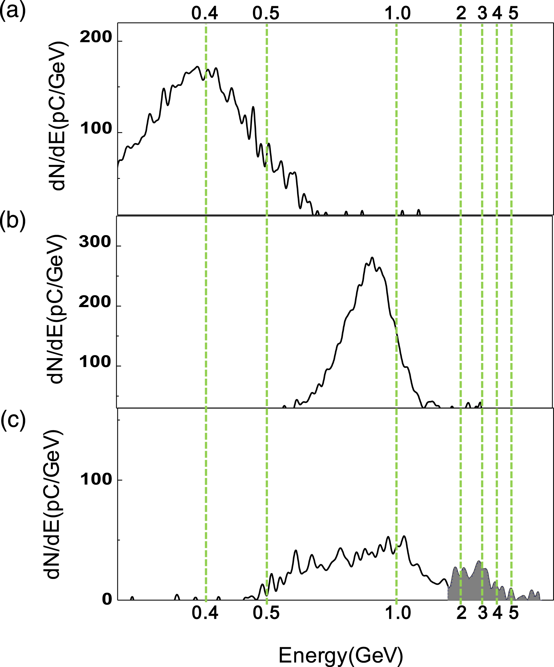
Figure 2. Electron beam energy spectra obtained from the experiment[Reference Kim, Pae, Cha, Kim, Yu, Sung, Lee, Jeong and Lee6], where a 212-TW, 60-fs laser pulse is focused on a  $1/e^{2}$ spot radius of
  $r_{L}=21\,{\rm\mu}\text{m}$ producing
  $a_{0}=3.7$ at the entrance of a gas jet for three cases consisting of (a) a 4-mm long single stage with
  $n_{e}=2.1\times 10^{18}\,\text{cm}^{-3}$, (b) a 10-mm long single stage with
  $n_{e}=1.3\times 10^{18}\,\text{cm}^{-3}$ and (c) two stages comprising a 4-mm long injector with
  $n_{e}=2\times 10^{18}\,\text{cm}^{-3}$ and a 10-mm long accelerator with
 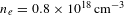 $n_{e}=0.8\times 10^{18}\,\text{cm}^{-3}$.
In Ref. [Reference Kim, Pae, Cha, Kim, Yu, Sung, Lee, Jeong and Lee6], a 212-TW, 60-fs laser pulse is focused on a  $1/e^{2}$ spot radius of
  $r_{L}=21\,{\rm\mu}\text{m}$, producing
  $a_{0}=3.7$ at the entrance of a gas jet for three cases consisting of a 4-mm long single stage with
 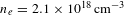 $n_{e}=2.1\times 10^{18}\,\text{cm}^{-3}$, a 10-mm long single stage with
 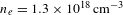 $n_{e}=1.3\times 10^{18}\,\text{cm}^{-3}$, and two stages comprising a 4-mm long injector with
  $n_{e}=2\times 10^{18}\,\text{cm}^{-3}$ and a 10-mm long accelerator with
 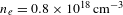 $n_{e}=0.8\times 10^{18}\,\text{cm}^{-3}$. As shown in Figure 2, the accelerated electron beams for the three cases have peak energies of 0.35, 0.87 and 3 GeV, respectively, and total loaded charges of 88, 110 and 80 pC, respectively. From Equations (3) and (4), the dimensionless matched spot radius
  $R_{m}=k_{p}r_{m}$ and the correction factor of the group velocity
  ${\it\kappa}_{\text{self}}={\it\kappa}_{\text{ch}}(a_{0}^{2},0)$ are
  $R_{m}=2.0$ and
  ${\it\kappa}_{\text{self}}=1.48$, respectively, at
  $a_{0}=3.7$. Since the matched spot radius is
  $r_{m}=7.3\,{\rm\mu}\text{m}$ for the 4-mm single-stage case,
  $r_{m}=9.3\,{\rm\mu}\text{m}$ for the 10-mm single-stage case and
  $r_{m}=7.5\,{\rm\mu}\text{m}$ in the injector jet and
  $r_{m}=12\,{\rm\mu}\text{m}$ in the accelerator jet for the two-stage case, respectively, it is inferred that a laser pulse with a focused spot radius of
  $r_{L}=21\,{\rm\mu}\text{m}$ is initially self-focused down to the matched spot radius. Using Equations (20) and (21) and assuming the electron beam size
  $k_{p}{\it\sigma}_{b}=1$, the field reduction factor
  ${\it\alpha}$ is calculated as
 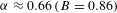 ${\it\alpha}\approx 0.66\,(B=0.86)$ for the 4-mm single-stage case,
 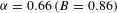 ${\it\alpha}=0.66\,(B=0.86)$ for the 10-mm single-stage case and
 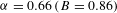 ${\it\alpha}=0.66\,(B=0.86)$ in the injector/
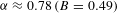 ${\it\alpha}\approx 0.78\,(B=0.49)$ in the accelerator for the two-stage case. From Equation (13), the dephasing length is
  $L_{\text{dp}}\approx 23.1\,\text{mm}$ for the 4-mm single-stage case,
  $L_{\text{dp}}\approx 47.4\,\text{mm}$ for the 10-mm single-stage case and
  $L_{\text{dp}}\approx 24.9\,\text{mm}$ in the injector/
 $L_{\text{dp}}\approx 98.3\,\text{mm}$ in the accelerator for the two-stage case. The pump depletion length due to pulse-front erosion is
  $L_{\text{pd}}\approx 14.9\,\text{mm}$ for the 4-mm single-stage case,
  $L_{\text{pd}}\approx 24.1\,\text{mm}$ for the 10-mm single-stage case and
  $L_{\text{pd}}\approx 15.7\,\text{mm}$ in the injector/
 $L_{\text{pd}}\approx 39.2\,\text{mm}$ in the accelerator for the two-stage case. From Equation (23), the beam energy is estimated to be
  $E_{b}\approx 353~\text{MeV}$ with an effective acceleration length of
  $L_{\text{acc}}=2\,\text{mm}$ for the 4-mm single-stage case and
  $E_{b}\approx 1.02\;\text{GeV}$ with
  $L_{\text{acc}}=8\,\text{mm}$ for the 10-mm single-stage case. For the two-stage case, the output energy of the injector is
  $E_{b}\approx 409\;\text{MeV}$ with
  $L_{\text{acc}}\approx 2.5\,\text{mm}$ and the output energy of the accelerator stage reaches
  $E_{b}\approx 2.46~\text{GeV}$ with
  $L_{\text{acc}}\approx 10\,\text{mm}$, assuming that the injection energy is
  $E_{b0}\approx 409\;\text{MeV}$ and the focused spot size at the entrance of the accelerator stage is decreased to
  $r_{L}=7.5\,{\rm\mu}\text{m}$ due to self-focusing in the injector stage, increasing the normalized vector potential up to
  $a_{0}\approx 10.4$. In this experiment, most of the charge produced in the injector is injected into the accelerator stage, while the large energy spread is attributed to the fact that the accelerator length is shorter than the dephasing length at which the energy compression takes place in the phase space as well as the maximum energy.
4. Design of 10-GeV-level laser plasma accelerators
At present, the most near-term prospects for 10-GeV-level laser plasma acceleration are confidently given by the scaling and methods described in the previous section. Here, we consider design examples of laser plasma accelerators capable of delivering 10-GeV electron beams with bunch charges of 160 pC ( $10^{9}$ electrons per bunch) for three cases: a self-guided laser plasma accelerator in the bubble regime with
  $a_{0}=3$, a channel-guided laser plasma accelerator in the bubble regime with
  $a_{0}=2$ and a channel-guided laser plasma accelerator in the quasi-linear regime with
  $a_{0}=1.5$. For all three cases, we present design parameters for the laser and plasma for a driving laser wavelength of 800 nm. Table 2 shows the design parameters of the 10-GeV laser plasma accelerators for the abovementioned three cases and a 40-GeV laser plasma accelerator with
  $a_{0}=2$ and a beam loading charge of 300 pC by comparison with the results of 3D PIC simulation from the Lorentz-boosted frame OSIRIS code[Reference Martins, Fonseca, Lu, Mori and Silva16]. The design parameters for the 40-GeV laser plasma accelerator are in good agreement with the PIC simulation results in terms of the operating plasma density, the accelerator length, i.e., the dephasing length, the matched spot radius and the matched power. The design formulas we used to evaluate these parameters are described in the following.
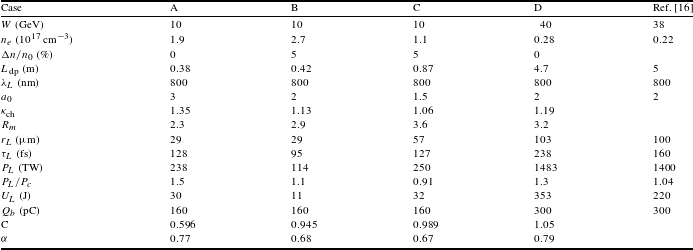
Table 2. Design parameters for 10-GeV-level laser plasma accelerators in comparison with the results of the 3D PIC simulation[Reference Martins, Fonseca, Lu, Mori and Silva16]. Case A stands for the self-guided case in the bubble regime, designed by the formulas given in Section 4.1, case B for the self-guided case in the bubble regime, designed by the formulas given in Section 4.2, case C for the channel-guided case in the quasi-linear regime, designed by the formulas given in Section 4.3, and case D for the self-guided case in the bubble regime at 40 GeV, designed by the formulas given in Section 4.1.
4.1. Self-guided laser plasma accelerator in the bubble regime
For a given energy gain  $W$, the operating plasma density is determined from Equation (11) as
 $$\begin{eqnarray}\displaystyle n_{e} & = & \displaystyle \frac{2}{3}{\it\alpha}{\it\kappa}_{\text{self}}a_{0}\frac{n_{c}}{{\rm\Delta}{\it\gamma}_{\max }}\nonumber\\ \displaystyle & {\approx} & \displaystyle 5.94\times 10^{16}\,[\text{cm}^{-3}]\,{\it\kappa}_{\text{self}}a_{0}\left(\frac{0.8\,{\rm\mu}\text{m}}{{\it\lambda}_{L}}\right)^{2}\left(\frac{10~\text{GeV}}{W/{\it\alpha}}\right).\nonumber\\ \displaystyle & & \displaystyle\end{eqnarray}$$
The accelerator length, equal to the dephasing length, becomes
 $$\begin{eqnarray}\displaystyle L_{\text{acc}} & = & \displaystyle L_{\text{dp}}\approx \sqrt{\frac{3}{2}}\frac{({\rm\Delta}{\it\gamma}_{\max }/{\it\alpha})^{3/2}}{{\it\pi}a_{0}{\it\kappa}_{\text{self}}^{1/2}}{\it\lambda}_{L}\nonumber\\ \displaystyle & {\approx} & \displaystyle \frac{0.9\,[\text{m}]}{a_{0}{\it\kappa}_{\text{self}}^{1/2}}\left(\frac{{\it\lambda}_{L}}{0.8\,{\rm\mu}\text{m}}\right)\left(\frac{W/{\it\alpha}}{10~\text{GeV}}\right)^{3/2},\end{eqnarray}$$
 while the pump depletion length due to pulse-front erosion is given by  $L_{\text{pd}}\approx c{\it\tau}_{L}n_{c}/n_{e}$. The dephasing length should be less than the pump depletion length, i.e.,
  $L_{\text{pd}}\geqslant L_{\text{dp}}$. Therefore, the pulse length is set to be
  $c{\it\tau}_{L}\geqslant (2/3{\it\pi})\sqrt{a_{0}}{\it\kappa}_{\text{self}}{\it\lambda}_{p}$.
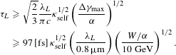 $$\begin{eqnarray}\displaystyle {\it\tau}_{L} & {\geqslant} & \displaystyle \sqrt{\frac{2}{3}}\frac{{\it\lambda}_{L}}{{\it\pi}c}{\it\kappa}_{\text{self}}^{1/2}\left(\frac{{\rm\Delta}{\it\gamma}_{\max }}{{\it\alpha}}\right)^{1/2}\nonumber\\ \displaystyle & {\geqslant} & \displaystyle 97\,[\text{fs}]\,{\it\kappa}_{\text{self}}^{1/2}\left(\frac{{\it\lambda}_{L}}{0.8\,{\rm\mu}\text{m}}\right)\left(\frac{W/{\it\alpha}}{10~\text{GeV}}\right)^{1/2}.\end{eqnarray}$$
The matched spot radius becomes
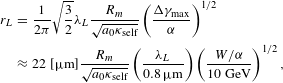 $$\begin{eqnarray}\displaystyle r_{L} & = & \displaystyle \frac{1}{2{\it\pi}}\sqrt{\frac{3}{2}}{\it\lambda}_{L}\frac{R_{m}}{\sqrt{a_{0}{\it\kappa}_{\text{self}}}}\left(\frac{{\rm\Delta}{\it\gamma}_{\max }}{{\it\alpha}}\right)^{1/2}\nonumber\\ \displaystyle & {\approx} & \displaystyle 22\;[{\rm\mu}\text{m}]\frac{R_{m}}{\sqrt{a_{0}{\it\kappa}_{\text{self}}}}\left(\frac{{\it\lambda}_{L}}{0.8\,{\rm\mu}\text{m}}\right)\left(\frac{W/{\it\alpha}}{10~\text{GeV}}\right)^{1/2},\quad\end{eqnarray}$$
 where  $R_{m}(a_{0}^{2},0)=k_{p}r_{L}$ is the dimensionless matched spot radius given by Equation (3) for self-guiding,
  ${\rm\Delta}n/n_{0}=0$. The matched power is calculated as
 $$\begin{eqnarray}\displaystyle P_{L} & = & \displaystyle \frac{k_{p}^{2}r_{L}^{2}a_{0}^{2}}{32}P_{c}=\frac{51}{64}\,[\text{GW}]\,\frac{a_{0}R_{m}^{2}}{{\it\kappa}_{\text{self}}}\frac{{\rm\Delta}{\it\gamma}_{\max }}{{\it\alpha}}\nonumber\\ \displaystyle & {\approx} & \displaystyle 15.6\,[\text{TW}]\,\frac{a_{0}R_{m}^{2}}{{\it\kappa}_{\text{self}}}\left(\frac{W/{\it\alpha}}{10~\text{GeV}}\right).\end{eqnarray}$$
The required pulse energy is
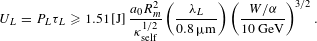 $$\begin{eqnarray}U_{L}=P_{L}{\it\tau}_{L}\geqslant 1.51\,[\text{J}]\,\frac{a_{0}R_{m}^{2}}{{\it\kappa}_{\text{self}}^{1/2}}\left(\frac{{\it\lambda}_{L}}{0.8\,{\rm\mu}\text{m}}\right)\left(\frac{W/{\it\alpha}}{10~\text{GeV}}\right)^{3/2}.\end{eqnarray}$$
 The field reduction factor  ${\it\alpha}$ for loading charge
  $Q_{b}$ up to a given energy
  $W$ is obtained by solving the equation
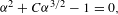 $$\begin{eqnarray}{\it\alpha}^{2}+C{\it\alpha}^{3/2}-1=0,\end{eqnarray}$$
 where the coefficient  $C$ is given as
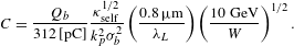 $$\begin{eqnarray}C=\frac{Q_{b}}{312\,[\text{pC}]}\frac{{\it\kappa}_{\text{self}}^{1/2}}{k_{p}^{2}{\it\sigma}_{b}^{2}}\left(\frac{0.8\,{\rm\mu}\text{m}}{{\it\lambda}_{L}}\right)\left(\frac{10~\text{GeV}}{W}\right)^{1/2}.\end{eqnarray}$$
4.2. Channel-guided laser plasma accelerator in the bubble regime
The operating plasma density is determined by
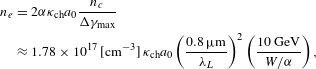 $$\begin{eqnarray}\displaystyle n_{e} & = & \displaystyle 2{\it\alpha}{\it\kappa}_{\text{ch}}a_{0}\frac{n_{c}}{{\rm\Delta}{\it\gamma}_{\max }}\nonumber\\ \displaystyle & {\approx} & \displaystyle 1.78\times 10^{17}\,[\text{cm}^{-3}]\,{\it\kappa}_{\text{ch}}a_{0}\left(\frac{0.8\,{\rm\mu}\text{m}}{{\it\lambda}_{L}}\right)^{2}\left(\frac{10~\text{GeV}}{W/{\it\alpha}}\right),\nonumber\\ \displaystyle & & \displaystyle\end{eqnarray}$$
and the accelerator length becomes
 $$\begin{eqnarray}\displaystyle L_{\text{stage}} & = & \displaystyle L_{\text{dp}}\approx \frac{{\it\lambda}_{L}}{\sqrt{2}{\it\pi}{\it\kappa}_{\text{ch}}^{1/2}a_{0}}\left(\frac{{\rm\Delta}{\it\gamma}_{\max }}{{\it\alpha}}\right)^{3/2}\nonumber\\ \displaystyle & {\approx} & \displaystyle \frac{0.5\,[\text{m}]}{{\it\kappa}_{\text{ch}}^{1/2}a_{0}}\left(\frac{{\it\lambda}_{L}}{0.8\,{\rm\mu}\text{m}}\right)\left(\frac{W/{\it\alpha}}{10~\text{GeV}}\right)^{3/2}.\end{eqnarray}$$
The pump depletion length, at which the total field energy becomes half of the initial laser energy, is given by
 $$\begin{eqnarray}\displaystyle L_{\text{pd}} & {\approx} & \displaystyle \frac{\sqrt{{\it\pi}}}{2{\it\alpha}^{2}}a_{0}{\it\sigma}_{L}\frac{n_{c}}{n_{e}}=\frac{1}{4}\sqrt{\frac{{\it\pi}}{\ln 2}}\frac{a_{0}c{\it\tau}_{L}}{{\it\alpha}^{2}}\frac{n_{c}}{n_{e}}\nonumber\\ \displaystyle & {\approx} & \displaystyle \frac{0.156\,[\text{m}]}{{\it\alpha}^{2}{\it\kappa}_{\text{ch}}}\left(\frac{W/{\it\alpha}}{10~\text{GeV}}\right)\left(\frac{{\it\tau}_{L}}{100\,\text{fs}}\right),\end{eqnarray}$$
 where  ${\it\sigma}_{L}=c{\it\tau}_{L}/(2\sqrt{\ln 2})\approx 0.6c{\it\tau}_{L}$ is the rms pulse length. The requirement for the accelerator length
 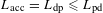 $L_{\text{acc}}=L_{\text{dp}}\leqslant L_{\text{pd}}$ bounds the minimum pulse duration as
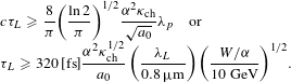 $$\begin{eqnarray}\displaystyle \begin{array}{@{}l@{}}\displaystyle c{\it\tau}_{L}\geqslant \frac{8}{{\it\pi}}\left(\frac{\ln 2}{{\it\pi}}\right)^{1/2}\frac{{\it\alpha}^{2}{\it\kappa}_{\text{ch}}}{\sqrt{a_{0}}}{\it\lambda}_{p}\quad \text{or}\quad \\ \displaystyle {\it\tau}_{L}\geqslant 320\,[\text{fs}]\frac{{\it\alpha}^{2}{\it\kappa}_{\text{ch}}^{1/2}}{a_{0}}\left(\frac{{\it\lambda}_{L}}{0.8\,{\rm\mu}\text{m}}\right)\left(\frac{W/{\it\alpha}}{10~\text{GeV}}\right)^{1/2}.\end{array} & & \displaystyle\end{eqnarray}$$
The matched spot radius becomes
 $$\begin{eqnarray}\displaystyle r_{L} & = & \displaystyle \frac{{\it\lambda}_{L}}{2{\it\pi}}\left(\frac{n_{c}}{n_{e}}\right)^{1/2}R_{m}\nonumber\\ \displaystyle & {\approx} & \displaystyle 12.6\,[{\rm\mu}\text{m}]\frac{R_{m}}{\sqrt{{\it\kappa}_{\text{ch}}a_{0}}}\left(\frac{{\it\lambda}_{L}}{0.8\,{\rm\mu}\text{m}}\right)\!\left(\frac{W/{\it\alpha}}{10~\text{GeV}}\right)^{1/2},\nonumber\\ \displaystyle & & \displaystyle\end{eqnarray}$$
 where 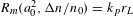 $R_{m}(a_{0}^{2},{\rm\Delta}n/n_{0})=k_{p}r_{L}$ is the dimensionless matched spot radius given by Equation (3). The matched power is calculated as
 $$\begin{eqnarray}P_{L}=\frac{k_{p}^{2}r_{L}^{2}a_{0}^{2}}{32}P_{c}\approx 5.2\,[\text{TW}]\frac{a_{0}R_{m}^{2}}{{\it\kappa}_{\text{ch}}}\left(\frac{W/{\it\alpha}}{10~\text{GeV}}\right),\end{eqnarray}$$
and the required pulse energy is
 $$\begin{eqnarray}U_{L}=P_{L}{\it\tau}_{L}\geqslant 1.66\,[\text{J}]\frac{{\it\alpha}^{2}R_{m}^{2}}{{\it\kappa}_{\text{ch}}^{1/2}}\left(\frac{{\it\lambda}_{L}}{0.8\,{\rm\mu}\text{m}}\right)\left(\frac{W/{\it\alpha}}{10~\text{GeV}}\right)^{3/2}.\end{eqnarray}$$
 The field reduction factor  ${\it\alpha}$ is determined from the coefficient
  $C$, given by
 $$\begin{eqnarray}C\equiv \frac{Q_{b}}{180\,[\text{pC}]}\frac{{\it\kappa}_{\text{self}}^{1/2}}{k_{p}^{2}{\it\sigma}_{b}^{2}}\left(\frac{0.8\,{\rm\mu}\text{m}}{{\it\lambda}_{L}}\right)\left(\frac{10\,\text{GeV}}{W}\right)^{1/2}.\end{eqnarray}$$
4.3. Channel-guided laser plasma accelerator in the quasi-linear regime
For a given  $a_{0}\leqslant 1.7$, the pulse duration is given by
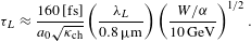 $$\begin{eqnarray}{\it\tau}_{L}\approx \frac{160\,[\text{fs}]}{a_{0}\sqrt{{\it\kappa}_{\text{ch}}}}\left(\frac{{\it\lambda}_{L}}{0.8\,{\rm\mu}\text{m}}\right)\left(\frac{W/{\it\alpha}}{10\,\text{GeV}}\right)^{1/2}.\end{eqnarray}$$
For this pulse duration, the operating plasma density becomes
 $$\begin{eqnarray}n_{e}\approx 6.8\times 10^{16}\,[\text{cm}^{-3}]\,{\it\kappa}_{\text{ch}}a_{0}^{2}\left(\frac{0.8\,{\rm\mu}\text{m}}{{\it\lambda}_{L}}\right)^{2}\left(\frac{10\,\text{GeV}}{W/{\it\alpha}}\right).\end{eqnarray}$$
 Thus, the required accelerator length  $L_{\text{acc}}$ can be set to be
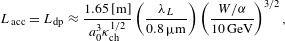 $$\begin{eqnarray}L_{\text{acc}}=L_{\text{dp}}\approx \frac{1.65\,[\text{m}]}{a_{0}^{3}{\it\kappa}_{\text{ch}}^{1/2}}\left(\frac{{\it\lambda}_{L}}{0.8\,{\rm\mu}\text{m}}\right)\left(\frac{W/{\it\alpha}}{10\,\text{GeV}}\right)^{3/2},\end{eqnarray}$$
 where  $n_{c}/n_{e}$ is given by Equation (9). The matched spot radius is calculated from
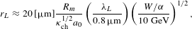 $$\begin{eqnarray}r_{L}\approx 20\,[{\rm\mu}\text{m}]\frac{R_{m}}{{\it\kappa}_{\text{ch}}^{1/2}a_{0}}\left(\frac{{\it\lambda}_{L}}{0.8\,{\rm\mu}\text{m}}\right)\left(\frac{W/{\it\alpha}}{10~\text{GeV}}\right)^{1/2},\end{eqnarray}$$
 where  $R_{m}=k_{p}r_{L}$ is the dimensionless matched spot radius for a given
  $a_{0}$ and
  ${\rm\Delta}n/n_{0}$, given by Equation (3). The required peak power of the laser pulse is given by
 $$\begin{eqnarray}P_{L}=\frac{k_{p}^{2}r_{L}^{2}a_{0}^{2}}{32}P_{c}\approx 13.7\,[\text{TW}]\frac{R_{m}^{2}}{{\it\kappa}_{\text{ch}}}\left(\frac{W/{\it\alpha}}{10\,\text{GeV}}\right),\end{eqnarray}$$
and the required pulse energy becomes
 $$\begin{eqnarray}U_{L}=P_{L}{\it\tau}_{L}\approx 2.2\,[\text{J}]\frac{R_{m}^{2}}{a_{0}{\it\kappa}_{\text{ch}}^{3/2}}\left(\frac{{\it\lambda}_{L}}{0.8\,{\rm\mu}\text{m}}\right)\left(\frac{W/{\it\alpha}}{10\,\text{GeV}}\right)^{3/2}.\end{eqnarray}$$
 The field reduction factor  ${\it\alpha}$ is determined from the coefficient
  $C$, given by
 $$\begin{eqnarray}C\equiv \frac{Q_{b}}{111\,[\text{pC}]}\frac{{\it\kappa}_{\text{self}}^{1/2}}{a_{0}k_{p}^{2}{\it\sigma}_{b}^{2}}\left(\frac{0.8\,{\rm\mu}\text{m}}{{\it\lambda}_{L}}\right)\left(\frac{10\,\text{GeV}}{W}\right)^{1/2}.\end{eqnarray}$$
5. Conclusion
We have provided an overview of recent progress in laser plasma accelerators from the perspective of experiments on the production of GeV-level electron beams, and scaling formulas to describe energy gain for a self-guided laser plasma accelerator in the bubble regime ( $a_{0}\geqslant 2$), a channel-guided laser plasma accelerator in the bubble regime (
 $a_{0}\geqslant 2$) and a channel-guided laser plasma accelerator in the quasi-linear regime (
 $a_{0}<2$). Although most previous experiments have been focused on electron injection into the plasma bubble and the production of high-quality electron beams with small energy spread and emittance, employing a millimeter-scale gas jet, recent experimental results beyond 1-GeV acceleration allow us to test the scaling formulas in depth, which are necessary for the design of the operating parameters of laser plasma accelerators to satisfy requirements such as energy gain and beam charge. Taking account of the group velocity correction factor
  ${\it\kappa}_{\text{ch}}$ in the propagation of laser pulses with relativistic intensity, characterized by
  $a_{0}$, through plasma channels, including initially uniform plasma with
  ${\rm\Delta}n/n_{0}=0$ and a preformed plasma channel with
  ${\rm\Delta}n/n_{0}\neq 0$, provides the correct accelerator length equal to the dephasing length as well as the proper operating plasma density. Meanwhile, we found that the accelerating field reduction factor
  ${\it\alpha}$ due to beam loading can be properly evaluated by applying the resultant scaling formulas to recent experimental results for multi-GeV laser plasma accelerators[Reference Wang, Zgadzaj, Fazel, Li, Yi, Zhang, Henderson, Chang, Korzekwa, Tsai, Pai, Quevedo, Dyer, Gaul, Martinez, Bernstein, Borger, Spinks, Donovan, Khudik, Shvets, Ditmire and Downer5, Reference Kim, Pae, Cha, Kim, Yu, Sung, Lee, Jeong and Lee6], leading to self-consistent design parameters for the driving laser pulse achieving the requirement of beam energy and charge. Independently, we confirmed that the accelerating field reduction factor
  ${\it\alpha}$ can be obtained from the simple analytic formulas Equations (20)–(22), indicating good agreement with that obtained from 3D PIC simulation results[Reference Martins, Fonseca, Lu, Mori and Silva16, Reference Lu, Tzoufras, Joshi, Tsung, Mori, Vieira, Fonseca and Silva38]. A further detailed analysis on the beam loading effects such as bunch length and shape that affect the accelerating fields, energy gain and energy spread will be pursued in future work.
Acknowledgements
This work was supported by Project Code IBS-R012-D1. K. Nakajima was also supported by the National Natural Science Foundation of China (Project No. 51175324).


 Open access