

1 Introduction
Fiber laser systems with near-diffraction limited beam quality are important laser sources that can be used in various areas, such as achieving high-power lasers by beam combination[ Reference Ma, Wang, Leng, Xiao, Dong, Zhu, Du, Zhou, Xu, Si, Liu and Zhao 1 ], acquiring high-power visible light by frequency doubling[ Reference Gapontsev, Avdokhin, Kadwani, Samartsev, Platonov and Yagodkin 2 ] and realizing high-precision industry materials processing[ Reference Shi, Fang, Zhu, Norwood and Peyghambarian 3 ]. With the rapid development of double-clad fiber manufacture craft and high-brightness laser diode pump sources, the output powers have soared up to the multi-kilowatt level[ Reference Beier, Hupel, Kuhn, Hein, Nold, Proske, Sattler, Liem, Jauregui, Limpert, Haarlammert, Schreiber, Eberhardt and Tünnermann 4 – Reference Wang, Kitahara, Kiyoyama, Shirakura, Kurihara, Nakanishi, Yamamoto, Nakayama, Ikoma and Shima 6 ], and a 10-kW single-mode fiber laser was reported in 2009[ Reference Stiles 7 ]. However, because of the accumulated heat load at high average power, severe dynamic mode coupling, mode instability, has been triggered in fiber lasers[ Reference Tao, Wang and Zhou 8 , Reference Jauregui, Stihler and Limpert 9 ], which is the physical manifest of stimulated thermal Rayleigh scattering in the fiber, and currently limits the power scaling and application area expansion of fiber laser systems[ Reference Wirth, Schmidt, Tsybin, Schreiber, Eberhardt, Limpert, Tünnermann, Ludewigt, Gowin, Have and Jung 10 – Reference Dajani, Flores, Holten, Anderson, Pulford and Ehrenreich 12 ].
Owing to the far-reaching impact, mode instability in various fiber laser systems has been under extensive theoretical and experimental investigation in recent years, but most of the work involves fiber lasers employing end-coupled cladding-pumping (ECCP) schemes[ Reference Tao, Wang and Zhou 8 , Reference Jauregui, Stihler and Limpert 9 ]. Side-pumping schemes, especially distributed side-coupled cladding-pumped (DSCCP) fiber or GTWave fiber, are another good choice for high-power fiber laser systems[ Reference Zervas, Marshall and Kim 13 – Reference Zhan, Peng, Liu, Wang, Li, Wang, Ni, Sun, Jiang, Yu, Jiang, Wang, Jing and Lin 17 ], which represent one of the important technologies to enable high-power scaling of fiber lasers[ Reference Gapontsev, Berishev, Strougov and Chuyanov 18 – Reference Chen, Cao, Liu, Huang, Wang, Wang, Wang and Chen 24 ]. Impressive power results have been reported in Refs. [Reference Zhan, Peng, Liu, Wang, Li, Wang, Ni, Sun, Jiang, Yu, Jiang, Wang, Jing and Lin17, Reference Zhan, Wang, Peng, Liu, Li, Ni, Wang, Gao, Sun, Zhang, Yu, Wang, Jing and Lin22], where signal fiber with a large pump area and backward pumping scheme was employed to suppress mode instability[ Reference Zhan, Peng, Liu, Wang, Li, Wang, Ni, Sun, Jiang, Yu, Jiang, Wang, Jing and Lin 17 ]. Recently, researchers have reported mode instability in DSCCP lasers[ Reference Scarnera, Ghiringhelli, Malinowski, Codemard, Durkin and Zervas 25 , Reference Chen, Cao, Huang, Tian, Pan, Wang and Chen 26 ]. In systematic experimental investigations, it is a big challenge to change certain parameters while keeping the remaining parameters unchanged. This can be realized in theoretical study, which means that critical insights into the mode instability of DSCCP fiber lasers require the help of theoretical work. However, mode instability in DSCCP fiber has not been studied theoretically due to the lack of models taking side-coupling schemes into consideration. Because the pump power is gradually coupled into the cladding of signal fiber, the pump power distribution in DSCCP fiber is different from that in ECCP fiber[ Reference Huang, Cao, Guo, Hou and Chen 27 – Reference Bochkov and Slobozhanina 29 ]. It is known that the mode instability thresholds are dependent on the pump power distribution[ Reference Eznaveh, Galmiche, Lopez and Correa 30 , Reference Tao, Ma, Wang, Zhou and Liu 31 ], and the mode instability thresholds for DSCCP fiber lasers must be different from those of ECCP fiber laser systems, which need to be studied as the output power of DSCCP fiber amplifiers scales up to the multi-kilowatt level[ Reference Zhan, Wang, Peng, Wang, Ni, Wang, Wang, Jing and Lin 32 – Reference Zhan, Liu, Wang, Ke, Ni, Wang, Peng, Gao, Li, Lin, Wang, Jing and Lin 34 ]. One should also note that the transverse mode competition in DSCCP fiber, which has been well studied in ECCP fiber, has not been examined yet, and plays an important role in determining the beam quality[ Reference Gong, Yuan, Li, Yan, Zhang and Liao 35 – Reference Yu, Wang, Zhou, Xiao and Chen 38 ]. The previous rate equations of DSCCP fiber have not taken the transverse spatial profile into consideration[ Reference Huang, Cao, Guo, Hou and Chen 27 – Reference Bochkov and Slobozhanina 29 , Reference He, Liao, Zhang, Chen, Peng, Yang, Dai, Li and Li 39 ], which makes the study of transverse mode competition difficult.
In this paper, a semi-analytical model has been built by developing transversally resolved steady-state rate equations for DSCCP fiber, which has taken the side-pumping schemes, transverse mode competition and stimulated thermal Rayleigh scattering into consideration. The mode evolution in DSCCP fiber amplifiers has been investigated theoretically, which shows that DSCCP fiber can suppress mode instability, and is a promising method to achieve high-power mode-instability-free fiber lasers. The results are discussed with the latest understanding of mode instability.
2 Theoretical model
To model mode instability in the following cases, the semi-analytical stimulated thermal Rayleigh scattering model, which agrees well with fully numerical models[ Reference Tao, Ma, Wang, Zhou and Liu 40 , Reference Mermelstein 41 ], has been updated by incorporating the transversally resolved DSCCP fiber model. Assuming that all the power absorbed due to linear absorption is turned into heat, the volume heat-generation density Q(r, ϕ, z, t) of the quantum defect and linear absorption can be approximately expressed as
 \begin{align}Q\left(r,\phi, z,t\right)&\cong g\left(r,\phi, z,t\right)\left(\frac{v_{\mathrm{p}}-{v}_{\mathrm{s}}}{v_{\mathrm{s}}}\right){I}_{\mathrm{s}}\left(r,\phi, z,t\right)\notag\\&\quad+\gamma \left(r,\phi, z\right){I}_{\mathrm{s}}\left(r,\phi, z,t\right),\end{align}
where v p(s) represents the optical frequencies of pump (signal) light, I s is the intensity of the signal light, which is the coherent superposition of fiber modes[ Reference Tao, Wang, Zhou and Liu 42 ], γ(r, ϕ, z) is the linear absorption coefficient[ Reference Tao, Wang, Zhou and Liu 42 ] and g(r, ϕ, z, t) is the gain of the amplifier, which is given by
 \begin{align}g\left(r,\phi, z,t\right)=\left[\left({\sigma}_{\mathrm{s}}^{\mathrm{a}}+{\sigma}_{\mathrm{s}}^{\mathrm{e}}\right){n}_{\mathrm{u}}\left(r,\phi, z,t\right)-{\sigma}_{\mathrm{s}}^{\mathrm{a}}\right]{N}_{\mathrm{Yb}}\left(r,\phi \right),\end{align}
where ${\sigma}_{\mathrm{s}}^{\mathrm{a}}$
and
${\sigma}_{\mathrm{s}}^{\mathrm{a}}$
and ${\sigma}_{\mathrm{s}}^{\mathrm{e}}$
are the signal absorption and emission cross-sections, respectively,
${\sigma}_{\mathrm{s}}^{\mathrm{e}}$
are the signal absorption and emission cross-sections, respectively, ${\sigma}_{\mathrm{p}}^{\mathrm{a}}$
and
${\sigma}_{\mathrm{p}}^{\mathrm{a}}$
and ${\sigma}_{\mathrm{p}}^{\mathrm{e}}$
are the pump absorption and emission cross-sections, respectively, N
Yb(r, ϕ) is the doping profile[
Reference Smith and Smith
43
] and n
u(r, ϕ, z, t) is the steady-state population inversion fraction.
${\sigma}_{\mathrm{p}}^{\mathrm{e}}$
are the pump absorption and emission cross-sections, respectively, N
Yb(r, ϕ) is the doping profile[
Reference Smith and Smith
43
] and n
u(r, ϕ, z, t) is the steady-state population inversion fraction.
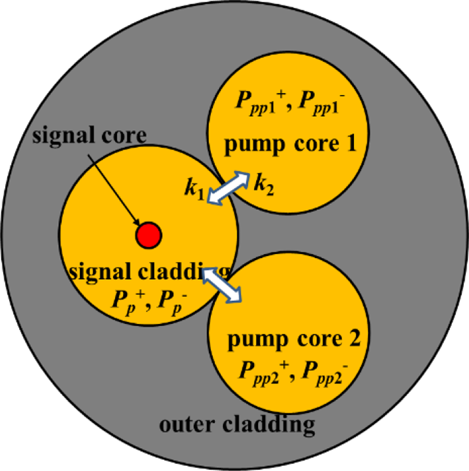
For the DSCCP fibers, the fiber consists of pump cores and signal fiber, and the pump light is optically coupled between them. So, the coupling of pump light between the pump cores and signal fiber should be considered in the model. Figure 1 shows the schematic diagram of DSCCP fiber with one pump core. For the sake of simplicity, a phenomenological model of DSCCP fiber amplifiers has been employed, which takes the coupling of pump light into account by employing the averaged coupling coefficients[ Reference Huang, Cao, Guo, Hou and Chen 27 ]. Similar to Refs. [Reference Tao, Ma, Wang, Zhou and Liu31, Reference Gong, Yuan, Li, Yan, Zhang and Liao35], the transversally resolved steady-state rate equations for DSCCP fiber lasers in Figure 1 can be expressed as
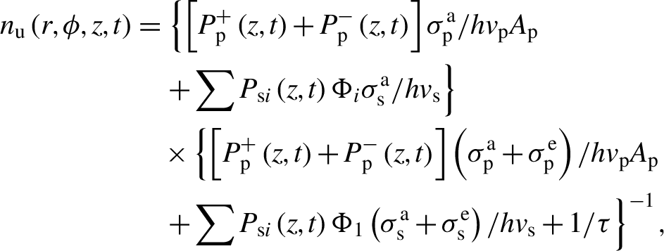 \begin{align}{n}_{\mathrm{u}}\left(r,\phi, z,t\right)&=\left\{\left[{P}_{\mathrm{p}}^{+}\left(z,t\right)+{P}_{\mathrm{p}}^{-}\left(z,t\right)\right]{\sigma}_{\mathrm{p}}^{\mathrm{a}}/{hv}_{\mathrm{p}}{A}_{\mathrm{p}}\right.\notag\\&\quad\left.+\sum {P}_{\mathrm{s}i}\left(z,t\right){\Phi}_i{\sigma}_{\mathrm{s}}^{\mathrm{a}}/{hv}_{\mathrm{s}}\right\}\notag\\&\quad\times\left\{\left[{P}_{\mathrm{p}}^{+}\left(z,t\right)+{P}_{\mathrm{p}}^{-}\left(z,t\right)\right]\left({\sigma}_{\mathrm{p}}^{\mathrm{a}}+{\sigma}_{\mathrm{p}}^{\mathrm{e}}\right)/ {hv}_{\mathrm{p}}{A}_{\mathrm{p}}\right.\notag\\&\quad\left.+\sum {P}_{\mathrm{s}i}\left(z,t\right){\Phi}_1\left({\sigma}_{\mathrm{s}}^{\mathrm{a}}+{\sigma}_{\mathrm{s}}^{\mathrm{e}}\right)/{hv}_{\mathrm{s}}+1/\tau\right\}^{-1},\end{align}
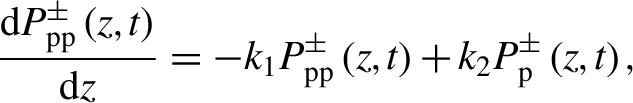 \begin{align}\frac{\mathrm{d}{P}_{\mathrm{p}\mathrm{p}}^{\pm}\left(z,t\right)}{\mathrm{d}z}=-{k}_1{P}_{\mathrm{p}\mathrm{p}}^{\pm}\left(z,t\right)+{k}_2{P}_{\mathrm{p}}^{\pm}\left(z,t\right),\end{align}
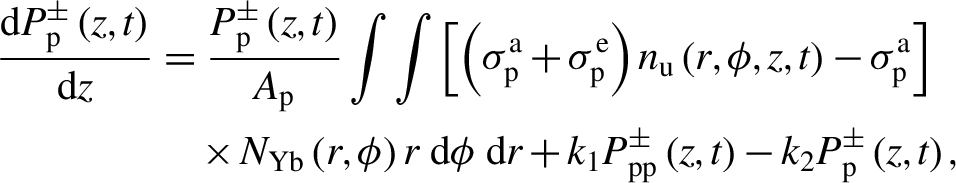 \begin{align}\frac{\mathrm{d}{P}_{\mathrm{p}}^{\pm}\left(z,t\right)}{\mathrm{d}z}&=\frac{P_{\mathrm{p}}^{\pm}\left(z,t\right)}{A_{\mathrm{p}}}\int \int \left[\left({\sigma}_{\mathrm{p}}^{\mathrm{a}}+{\sigma}_{\mathrm{p}}^{\mathrm{e}}\right){n}_{\mathrm{u}}\left(r,\phi, z,t\right)-{\sigma}_{\mathrm{p}}^{\mathrm{a}}\right]\notag\\&\quad\times{N}_{\mathrm{Yb}}\left(r,\phi \right)r\;\mathrm{d}\phi\;\mathrm{d}r+{k}_1{P}_{\mathrm{p}\mathrm{p}}^{\pm}\left(z,t\right)-{k}_2{P}_{\mathrm{p}}^{\pm}\left(z,t\right),\end{align}
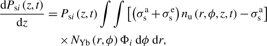 \begin{align}\frac{\mathrm{d}{P}_{\mathrm{s}i}\left(z,t\right)}{\mathrm{d}z}&={P}_{\mathrm{s}i}\left(z,t\right)\int \int \left[\left({\sigma}_{\mathrm{s}}^{\mathrm{a}}+{\sigma}_{\mathrm{s}}^{\mathrm{e}}\right){n}_{\mathrm{u}}\left(r,\phi, z,t\right)-{\sigma}_{\mathrm{s}}^{\mathrm{a}}\right]\notag\\&\quad\times{N}_{\mathrm{Yb}}\left(r,\phi \right){\Phi}_i\;\mathrm{d}\phi\;\mathrm{d}r,\end{align}
Schematic diagram of DSCCP fiber with one pump core.

 \begin{align}\frac{\mathrm{d}{P}_{\mathrm{p}\mathrm{p}}^{\pm}\left(z,t\right)}{\mathrm{d}z}=-{k}_1{P}_{\mathrm{p}\mathrm{p}}^{\pm}\left(z,t\right)+{k}_2{P}_{\mathrm{p}}^{\pm}\left(z,t\right),\end{align}
where ${P}_{\mathrm{p}\mathrm{p}}^{\pm}$
and
${P}_{\mathrm{p}\mathrm{p}}^{\pm}$
and ${P}_{\mathrm{p}\mathrm{p}}^{-}$
represent the forward and backward pump power in the pump core, respectively,
${P}_{\mathrm{p}\mathrm{p}}^{-}$
represent the forward and backward pump power in the pump core, respectively, ${P}_{\mathrm{p}}^{+}$
and
${P}_{\mathrm{p}}^{+}$
and ${P}_{\mathrm{p}}^{-}$
represent the pump light power in the signal fiber, P
si
is the signal power of fiber mode i, A
p = πR
2 is the area of the pump cladding of the signal fiber, with R being the pump cladding radius, τ is the ion upper-state lifetime, Φ
i
=ψiψi
* is the irradiance spatial profile of fiber mode i, normalized to 1 W[
Reference Dong
44
], k
1 is the averaged coupling coefficient of the pump light from the pump core to the signal cladding and k
2 is that from the signal cladding to the pump[
Reference Huang, Cao, Guo, Hou and Chen
27
]. As the averaged coupling coefficients can be detuned by controlling the fiber design, they are treated as free parameters to be explored, which range from 1 to 30 m–1[
Reference Huang, Cao, Guo, Hou and Chen
27
–
Reference Bochkov and Slobozhanina
29
,
Reference Xiao, Ren, Yan, Chen and Gong
45
,
Reference Xiao, Ren, Chen, Yan and Gong
46
]. The phenomenological model of DSCCP fiber can be related to the properties of the fiber design by accommodating the averaged coupling coefficients to the results of a fully numerical time-consuming model[
Reference Liu, Liu and Ke
47
]. Similar to the process in Ref. [Reference Jauregui, Eidam, Limpert and Tünnermann48], Equation (3) was first discretized to become programmable in a computer, which was then solved by using the Runge–Kutta methods. After the discretization of Equation (3), the double integral becomes double summation, which can be calculated by adding the discretized parts directly in the equally spaced spatial grid. The spatial grid spans a domain of 6R
c with the core at its center (R
c is the core radius of the signal fiber)[
Reference Smith and Smith
43
], and the grid steps of the discretization are chosen to keep the variation of the summation results less than 0.1% to maintain the accuracy of calculation.
${P}_{\mathrm{p}}^{-}$
represent the pump light power in the signal fiber, P
si
is the signal power of fiber mode i, A
p = πR
2 is the area of the pump cladding of the signal fiber, with R being the pump cladding radius, τ is the ion upper-state lifetime, Φ
i
=ψiψi
* is the irradiance spatial profile of fiber mode i, normalized to 1 W[
Reference Dong
44
], k
1 is the averaged coupling coefficient of the pump light from the pump core to the signal cladding and k
2 is that from the signal cladding to the pump[
Reference Huang, Cao, Guo, Hou and Chen
27
]. As the averaged coupling coefficients can be detuned by controlling the fiber design, they are treated as free parameters to be explored, which range from 1 to 30 m–1[
Reference Huang, Cao, Guo, Hou and Chen
27
–
Reference Bochkov and Slobozhanina
29
,
Reference Xiao, Ren, Yan, Chen and Gong
45
,
Reference Xiao, Ren, Chen, Yan and Gong
46
]. The phenomenological model of DSCCP fiber can be related to the properties of the fiber design by accommodating the averaged coupling coefficients to the results of a fully numerical time-consuming model[
Reference Liu, Liu and Ke
47
]. Similar to the process in Ref. [Reference Jauregui, Eidam, Limpert and Tünnermann48], Equation (3) was first discretized to become programmable in a computer, which was then solved by using the Runge–Kutta methods. After the discretization of Equation (3), the double integral becomes double summation, which can be calculated by adding the discretized parts directly in the equally spaced spatial grid. The spatial grid spans a domain of 6R
c with the core at its center (R
c is the core radius of the signal fiber)[
Reference Smith and Smith
43
], and the grid steps of the discretization are chosen to keep the variation of the summation results less than 0.1% to maintain the accuracy of calculation.
For fiber laser systems with a broad spectral bandwidth, for example, several nanometers, the coherent length is far shorter than the fiber length, and as a result the inter-mode coherent interference can be neglected[ Reference Wielandy 49 ] and the transverse mode competition is static. The irradiance-based model expressed in Equation (3) can be employed to study the static mode evolution. However, for narrow linewidth models with a spectral bandwidth substantially less than 1 nm, the inter-mode coherent interference can result in thermal-induced long-period grating and coupling power dynamically between fiber modes, which triggers the onset of mode instability. For relative intensity noise-induced mode instability, the high-order mode (HOM) fraction is given as[ Reference Tao, Ma, Wang, Zhou and Liu 50 ]
 \begin{align}&\xi (L)\approx {\xi}_0\exp \left[{\int}_0^{{L}}\mathrm{d}z\int \int g\left(r,\phi, z\right)\left({\psi}_2{\psi}_2-{\psi}_1{\psi}_1\right)r\;\mathrm{d}r\;\mathrm{d}\phi \right]\notag\\&\quad+\frac{\xi_0}{4}\sqrt{\frac{2\pi }{\int_0^{{L}}{P}_1(z)\left|\chi {''} \left({\Omega}_0,z\right)\right|\;\mathrm{d}z}}\notag\\&\quad\times\exp \left[{\int}_0^{{L}}\mathrm{d}z\int \int g\left(r,\phi, z\right)\left({\psi}_2{\psi}_2-{\psi}_1{\psi}_1\right)r\;\mathrm{d}r\;\mathrm{d}\phi \right]\notag\\&\quad{}\times {R}_{\mathrm{N}}\left({\Omega}_0\right)\exp \left[{\int}_0^{{L}}{P}_1(z)\chi \left({\Omega}_0,z\right)\;\mathrm{d}z\right],\end{align}
with
 \begin{align}\chi \left(\Omega \right)=2\frac{n_0{\omega}_2^2}{c^2{\beta}_2}\operatorname{Im}\left[\int \int \left({\overline{h}}_{12}+{\overline{h}}_{12} {'}\right){\psi}_1{\psi}_2r\;\mathrm{d}r\;\mathrm{d}\phi \right],\end{align}
 \begin{align}{\overline{h}}_{kl}\left(r,\phi, z\right)=\frac{\alpha {n}_2}{\pi}\sum \limits_v\sum \limits_{m=1}^{\infty}\frac{J_v\left({\delta}_m,r\right)}{N\left({\delta}_m\right)}\frac{B_{kl}\left(\phi, z\right)}{{\alpha \delta}_m^2-j\Omega},\end{align}
 \begin{align}{\overline{h}}_{kl} {'}\left(r,\phi, z\right)=\frac{\eta \alpha}{\pi \kappa}\sum \limits_v\sum \limits_{m=1}^{\infty}\frac{J_v\left({\delta}_m,r\right)}{N\left({\delta}_m\right)}\frac{B_{kl} {'}\left(\phi, z\right)}{{\alpha \delta}_m^2-j\Omega},\end{align}
 \begin{align}{B}_{kl}\left(\phi, z\right)&={\int}_0^{2\pi} \hbox{d}\phi {'}{\int}_0^R{g}_0{J}_v\left({\delta}_m,r {'}\right)\cos v\left(\phi -\phi {'}\right)\notag\\&\quad\times\frac{\psi_k\left(r {'},\phi {'}\right){\psi}_{\mathrm{l}}\left(r {'},\phi {'}\right)}{{\left(1+{I}_0/{I}_{\mathrm{saturation}}\right)}^2}\;\mathrm{d}r {'},\end{align}
 \begin{align}{B}_{kl} {'}\left(\phi, z\right)&={\int}_0^{2\pi} \hbox{d}\phi {'}{\int}_0^R\gamma \left(r {'},\phi {'}\right){J}_v\left({\delta}_m,r {'}\right)\cos v\notag\\&\quad\times\left(\phi -\phi {'}\right){\psi}_k\left(r {'},\phi {'}\right){\psi}_{\mathrm{l}}\left(r {'},\phi {'}\right)\;\mathrm{d}r {'},\end{align}
 \begin{align}\frac{1}{N\left({\delta}_m\right)}=\frac{1}{\int_0^R{rJ}_v^2\left({\delta}_m,r\right)\;\mathrm{d}r},\end{align}
 \begin{align}{n}_2=\frac{\eta }{\kappa_{\mathrm{T}}}\left(\frac{v_{\mathrm{p}}-{v}_{\mathrm{s}}}{v_{\mathrm{s}}}\right),\end{align}
 \begin{align}\Omega ={\omega}_1\hbox{--} {\omega}_2,\ \alpha =\kappa /\rho C,\end{align}
where ξ 0 is the initial HOM fraction, L is the length of the gain fiber, R N(Ω) is the relative intensity noise of the input signal, ρ is the density, C is the specific heat capacity, κ T is the thermal conductivity, η is the thermal-optic coefficient, ω 1 and ω 2 are the angular frequencies of the fundamental mode (FM) and the HOM, respectively, Jv is the Bessel function of the first kind, δm represents the positive roots of δmJv ′(δmR) + h q Jv(δm R)/κ = 0 (h q is the convection coefficient for the cooling fluid), Ω0 denotes the frequency of the maximum of χ(Ω) and χ ″(Ω) denotes the second derivative of χ(Ω) with respect to Ω. To calculate Equation (5), the parts are discretized first, and the double integral in the expressions becomes a double summation, which is then calculated by adding the discretized parts directly. The grid steps of the discretization have been chosen to keep the variation of the summation results less than 0.1% to maintain accuracy. The mode instability thresholds are defined as the signal power when 10% of the signal power has been transferred to the HOM, which means that ξ(L) = 0.1. The fiber parameters are listed in Table 1. These parameters are typical of high-power ytterbium-doped amplifiers, which are summarized from the references. The DSCCP fiber amplifiers are unbent, step-index fibers with uniform doping across the full core. Even though the following simulations are exemplified for a particular case, the qualitative behavior of the mode evolutions is similar for other cases, such as bent fibers, non-step-index fibers and confine-doped fibers.
Parameters of the test amplifier.

3 Numerical simulations
3.1 Static transverse mode competition in DSCCP fiber
For high-power industrial macro applications, such as metal cutting and welding, fiber lasers typically exhibit a broad spectral bandwidth. Thus, the mode interference and the related physical effects can be neglected, and the irradiance-based model can be employed to study the transverse mode competition in DSCCP fiber amplifiers. In the modeling, only the competition between the HOM with minimum loss and FM has been taken into consideration, which is because other HOMs could have higher loss and are much easier to suppress. In the context of step-index fiber, the loss of the LP11 mode is minimal, while the gain amplification is high[ Reference Huang, Kong, Leng, Zhou, Guo and Cheng 53 ].
The power distribution and fraction of the HOM in the DSCCP fiber amplifier have been calculated as shown in Figure 2. In Figure 2, N
Yb = 4×1025 m–3 and L = 5 m, which results in the residual pump power in the pump core being about 5%. For simplicity, the radius and refractive index of the signal cladding and pump fibers are taken to be the same, which results in the averaged coupling coefficients being nearly the same. The averaged coupling coefficient for the case in Table 1 is set to k = k
1 = k
2 = 2 m–1, which agrees well with the experimental results[
Reference Chen, Cao, Huang, Ren, Liu, Pan, Wang and Chen
54
]. The fraction of HOM was set to zero in Figure 2(a) and the input pump power was set to 500 W, while the initial HOM fraction was set to 0.1 in Figure 2(b). The other parameters are the same as those in Table 1. The backward pump power fraction is defined as $P_{\mathrm{pp}}^{-}(L)/[P_{\mathrm{pp}}^{+}(0)+P_{\mathrm{pp}}^{-}(L)]$
. It is revealed that, as the HOM experienced higher gain due to the population inversion saturation, or the transverse hole burning, the HOM fraction increases from 0.1 to more than 0.16 after the power boosting. Here, the transverse hole burning effect refers to that, when a laser beam with non-uniform transverse intensity is propagating in the fiber, the gain becomes more saturated where the intensity is highest. One can also see that the fraction of the HOM in the output laser increases as the fraction of pump power increases, which means that the backward pump configurations are slightly in favor of the amplification of the HOM compared with the forward pumps. This is due to the difference in the population inversion saturation, which has been altered by different pump power distributions.
$P_{\mathrm{pp}}^{-}(L)/[P_{\mathrm{pp}}^{+}(0)+P_{\mathrm{pp}}^{-}(L)]$
. It is revealed that, as the HOM experienced higher gain due to the population inversion saturation, or the transverse hole burning, the HOM fraction increases from 0.1 to more than 0.16 after the power boosting. Here, the transverse hole burning effect refers to that, when a laser beam with non-uniform transverse intensity is propagating in the fiber, the gain becomes more saturated where the intensity is highest. One can also see that the fraction of the HOM in the output laser increases as the fraction of pump power increases, which means that the backward pump configurations are slightly in favor of the amplification of the HOM compared with the forward pumps. This is due to the difference in the population inversion saturation, which has been altered by different pump power distributions.
(a) Power distribution and (b) fraction of the HOM in the DSCCP fiber amplifier.

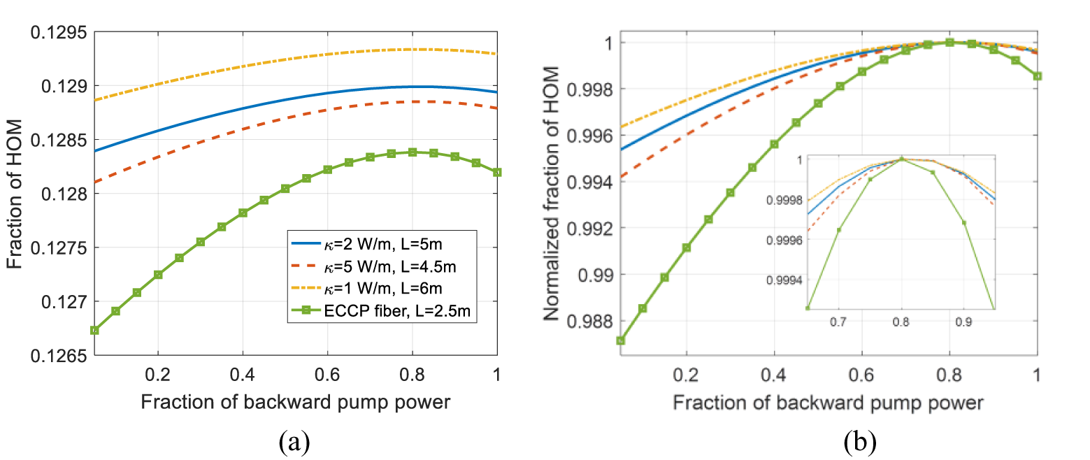
The fraction of the HOM as a function of the backward pump power ratio for different total pump powers and fiber lengths has also been calculated, and is shown in Figure 3. For Figure 3(a), the fiber length was set to be 5 m for all the cases while the total pump power was set to be 500 W for the cases considered in Figure 3(c). Other parameters were the same as those in Figure 2. As the HOM fraction for different cases is different in Figure 3(a), the normalized fraction of the HOM is calculated by dividing the fraction of the HOM by the corresponding maximal HOM fraction for the convenience of comparison, which is revealed in Figure 3(b). As the pump power increases, the effect of population inversion saturation is enhanced and the gain of the HOM increases, which results in the increase of the HOM ratio and the degradation of beam quality as the pump power increases[ Reference Wellmann, Bode, Wessels, Overmeyer, Neumann, Willke and Kracht 55 ]. As the fiber length increases, less pump power is required to achieve the same signal power amplification, which has the same effect as a pump power decrease. This results in the effect of population inversion saturation decreasing, which weakens the amplification due to the hole burning effect. On the other hand, the gain of the HOM is stronger for the longer gain fibers, which outweighs the influence of the hole burning effect, and results in the HOM ratio being higher for longer gain fibers. One can conclude that the population inversion saturation is in favor of the HOM in the context of transverse mode competition. One can also note from Figures 3(b) and 3(c) that there are optimal backward pump power fractions that result in maximal HOM amplifications. The optimal backward pump power fractions increase as the pump power increases or fiber length decreases, which means that there is a positive correlation between the optimal backward pump power fractions and the degree of saturation.
(a) Fraction of the HOM as a function of backward pump power ratio under different pump powers. (b) Normalized data of (a). (c) Fraction of the HOM as a function of the backward pump power ratio under different fiber lengths in the DSCCP fiber amplifier.

Then, the parameters of the fiber have been changed, and the HOM behavior with different core-to-cladding ratios is compared, which is shown in Figures 4(a)–4(d). The pump power is taken to be 50 W, whereas the seed power is 20 W for Figures 4(a)–4(d) and the coupling coefficient is 2 m–1. It is known that the degree of saturation would be reduced in a fiber with a smaller cladding, and increased in one with a larger cladding. One can easily understand the results in Figures 4(a) and 4(b), where the HOM fraction for 30/900 fiber is higher than that for the 30/250 counterpart. The results of Figures 4(c) and 4(d) seem abnormal, where the HOM fraction for 20/400 fiber is lower than that for the 50/400 counterpart, while the degree of saturation is stronger for 20/400 fiber. This is because the fiber mode profiles change as the core size increases, which leads to the FM profile being confined deeper into the central area of the fiber core, resulting in a larger core size, and the undepleted upper-state population at the boundary of the core increases. The transverse hole burning effect becomes weakened, which means that the HOM gain from the transverse hole burning effect reduces. On the other hand, the HOM profile is also confined deeper into the central area of the fiber core, and the HOM gains stronger amplification, which outweighs the impact of the transverse hole burning effect and results in a larger increase of the HOM fraction in 50/400 fiber. One can also see from Figures 4(b) and 4(d) that there are optimal backward pump power fractions, and the behavior has been confirmed by varying the seed power and averaged coupling coefficient. As the seed power is reduced to 5 W, there are also optimal backward pump power fractions, but they tend to shift to larger values, as shown in Figures 4(e) and 4(f). As the averaged coupling coefficient increases to 20 m–1, there are also optimal backward pump power fractions, and they tend to shift to slightly larger values, as shown in Figures 4(f) and 4(g). In the calculations of Figures 4(e)–4(g), the parameters are the same as in Figure 4(c) except the specified one. The seed power decrease and the averaged coupling coefficient increase result in the enhancement of the degree of saturation, which results in the optimal backward pump power fractions shifting to the larger side. One can further confirm the positive correlation between the optimal backward pump power fractions and the degree of saturation, which is true for various parameters.
(a) Fraction of the HOM and (b) normalized fraction of the HOM as a function of backward pump power ratio under different cladding sizes. (c) Fraction of the HOM and (d) normalized fraction of the HOM as a function of backward pump power ratio under different core sizes. (e) Fraction of the HOM and (f) normalized fraction of the HOM as a function of backward pump power ratio for 5 W seed power. (g) Fraction of the HOM and (h) normalized fraction of the HOM as a function of backward pump power ratio for k = 20 m–1.

The HOM fraction under various averaged coupling coefficients and ECCP fiber is shown in Figure 5. One can see that as the averaged coupling coefficient increases, the effect of population inversion saturation weakens and the gain of the HOM decreases, which results in the decrease of the HOM ratio. Comparing the results with those of the ECCP fiber, one can conclude that the population inversion saturation effect in the DSCCP fiber amplifier is stronger than that in the ECCP fiber amplifier, which means that the DSCCP fiber is inferior to the ECCP fiber in the aspect of suppressing transverse mode competition.
(a) Fraction of HOM as a function of backward pump power ratio for different gain fibers; (b) normalized data of (a).
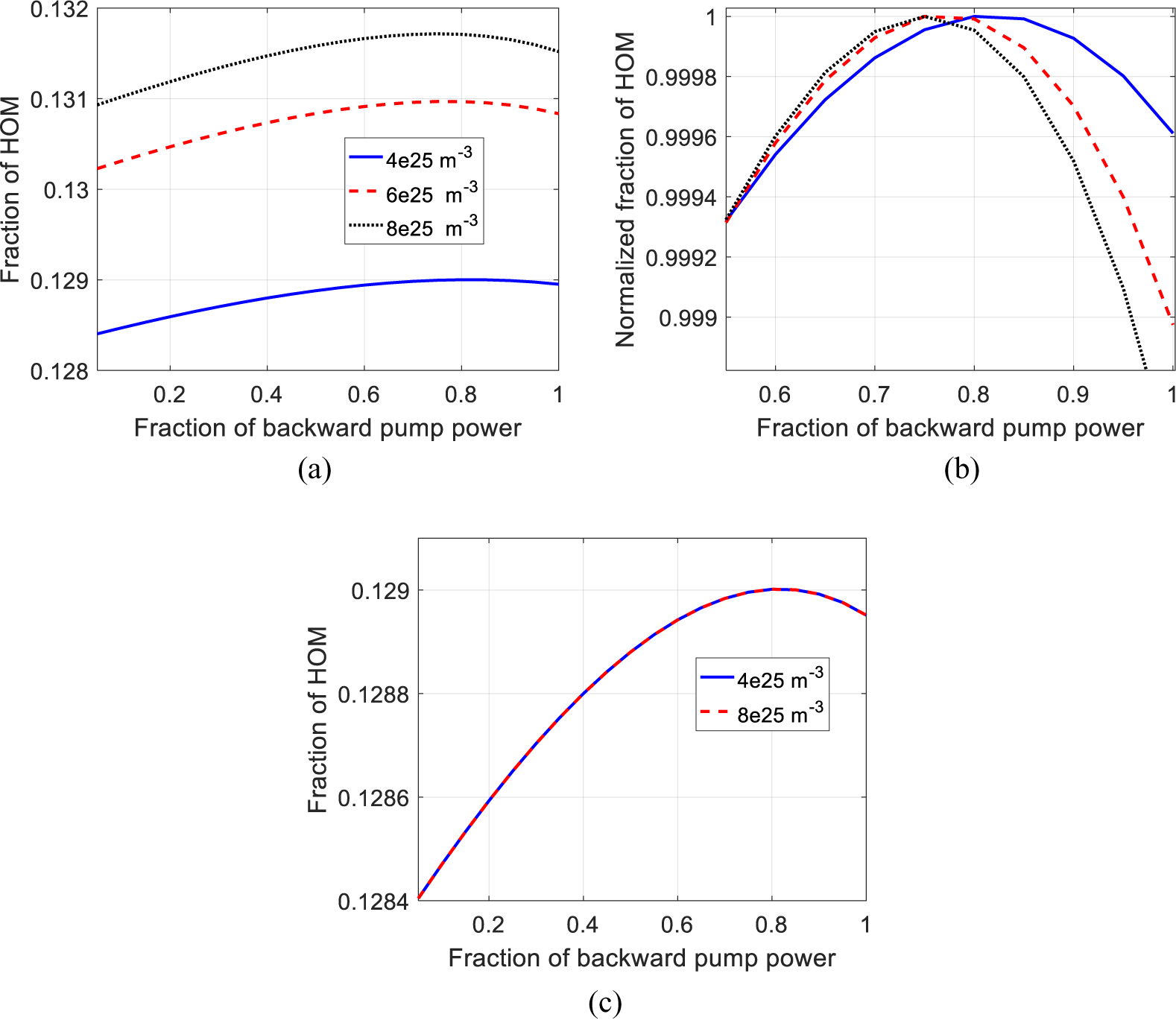
The HOM fraction for different dopant concentrations is shown in Figure 6. For Figures 6(a) and 6(b), the fiber length and the averaged coupling coefficient are 5 m and 2 m–1, respectively, and they are constant as the dopant concentration varies. For Figure 6(c), as the dopant concentration varies, the fiber length and the coupling coefficient are varied accordingly to ensure that the product of the fiber length and the dopant concentration and the product of the fiber length and the averaged coupling coefficient are constant. One can see from Figures 6(a) and 6(b) that the fraction of HOM increases as the dopant concentration increases, and the optimal backward pump power reduces, which is similar with the results in Figure 6(c). This is due to the fact that the pump absorption increases as the doping concentration increases, which is the same as the case when the fiber length increases and tends to increase the fraction of HOM. However, if the fiber length and the coupling coefficient are varied accordingly, the pump absorption remains the same, which leads to the constant fraction of HOM as the dopant concentration increases as shown in Figure 6(c).
(a) Fraction of the HOM as a function of backward pump power ratio for different dopant concentrations. (b) Normalized data of (a). (c) Fraction of the HOM as a function of backward pump power ratio for different dopant concentrations with k = 4 m–1 and L = 2.5 m.
3.2 Dynamic mode instability in one-pump-core DSCCP fiber amplifiers
For fiber lasers with a narrow linewidth, the mode interference-induced mode instability becomes inevitable at high average power, which has not been theoretically analyzed. In this section, we first study the mode instability threshold behavior as a function of the dopant concentration, the fiber length and the averaged coupling coefficient. By detailed calculation, we found that, as long as the product of the fiber length and the dopant concentration and the product of the fiber length and the averaged coupling coefficient are constant, the mode instability thresholds are the same, which means that the mode instability threshold for N Yb = 4 × 1025 m–3, L = 15 m, k = k 1 = k 2 = 2 m–1 is the same as that for N Yb = 2 × 1026 m–3, L = 3 m, k = 10 m–1. This is because the pump and signal power distributions are the same for these conditions, which results in the population inversion or hole burning effects being the same in the two cases. While other factors that have impact on mode instability remain untouched, the mode instability threshold is constant[ Reference Tao, Ma, Wang, Zhou and Liu 56 , Reference Xia and Yoo 57 ]. This is important for numerical calculation, which means that the length of the fiber can be shortened to save the calculation time by suitably choosing the dopant concentration and the averaged coupling coefficient. One should bear in mind that this is generally not the real situation, but rather a simulation trick. In practice, it is difficult to change only the dopant concentration while keeping the remaining parameters of the fiber unchanged[ Reference Ye, Petit, Koponen, Hu and Galvanauskas 58 ], such as core NA, photodarkening and bend loss of the HOM.
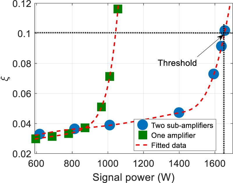
Before the following analysis, we will discuss the accuracy of the model in brief. The results of the ECCP fiber model agree well with other researchers’ results, and the error is less than 5%[ Reference Tao, Ma, Wang, Zhou and Liu 40 , Reference Mermelstein 41 ]. The model has been solved by the same method, so the accuracy of the model is also about 5%. To further confirm the accuracy of the model, the result calculated by the model has been compared with the previous experimental result. The fraction of the HOM as a function of output signal power for the evenly bi-directional pumping two-stage scheme has been calculated and is shown in Figure 7. In the calculation, all the parameters were set the same as those in Ref. [Reference Chen, Cao, Huang, Tian, Pan, Wang and Chen26]. The results of one amplifier have also been calculated for comparison. One can see that the HOM fraction increases as the signal power increases, and the mode instability threshold is about 1654 and 1040 W for two-stage and one-stage fiber amplifiers, respectively. In Ref. [Reference Chen, Cao, Huang, Tian, Pan, Wang and Chen26], the mode instability for the two-stage amplifier has been observed around 1625 W, and the error is less than 5%, which means that results of the model agree well with the experimental results, and the model can be employed to study the mode instability in DSCCP fiber with high accuracy. One can also find that mode instability for the two sub-amplifier system is about 60% higher than that for one amplifier, which means that mode instability can be increased by employing sub-amplifiers to form multi-stage systems. However, the length increases as the number of sub-amplifiers increases, which causes the onset of other nonlinear effects, which will not be discussed in the following sections.
The HOM fraction as a function of output signal power for the evenly bi-directional pumping case in Ref. [Reference Chen, Cao, Huang, Tian, Pan, Wang and Chen26].
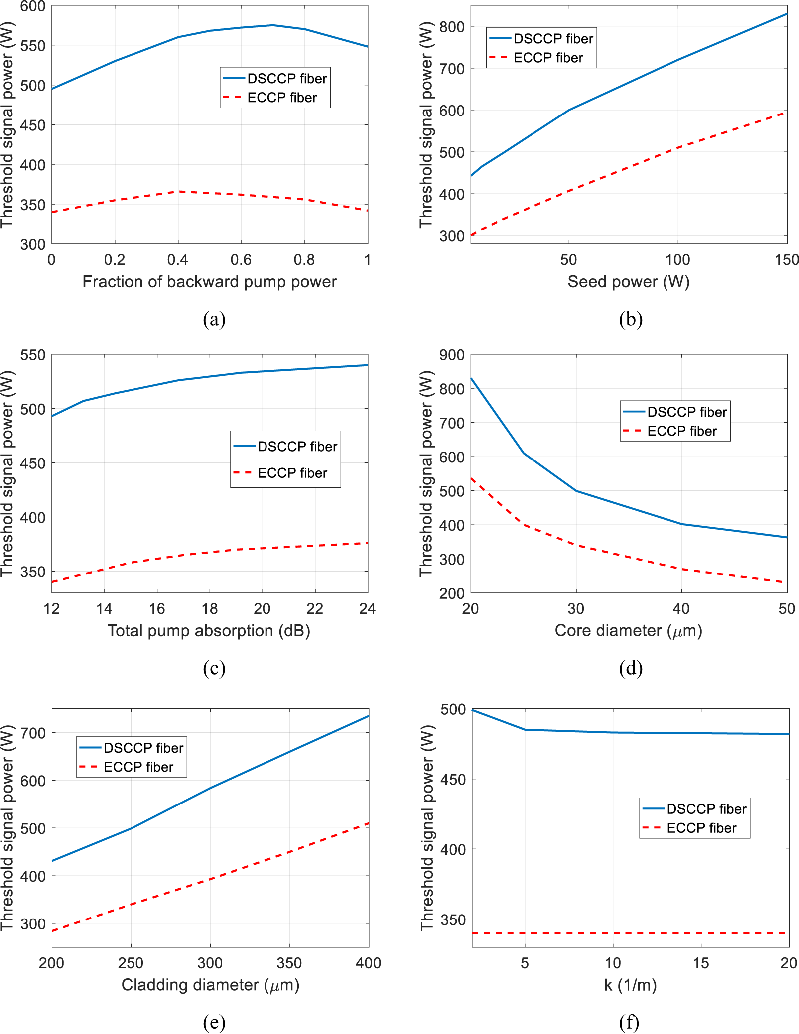
The thresholds as a function of different system parameters are shown in Figure 8. In the calculation, N Yb = 2 × 1025 m–3, L = 10 m and k = 1 m–1, except for the parameter under investigation. The other parameters are listed in Table 1. For Figures 8(b)–8(f), the backward pump power fraction is zero, corresponding to forward pumping schemes. In this case, the unabsorbed or residual pump power in the pump core is about 5%. The results of ECCP fiber, which has the same parameters as the signal fiber of the DSCCP fiber, have also been calculated for comparison and are shown in Figure 8. It can be seen from Figure 8(a) that the threshold increases as the backward pump power fraction increases until it reaches the maximum point. After the maximum point, the threshold decreases with the backward pump power fraction increasing, which is similar to the cases in Ref. [Reference Tao, Ma, Wang, Zhou and Liu31]. The optimal backward pump power fraction, which corresponds to the maximum threshold, for 30/250 fiber is 0.7, and the maximum threshold increment ratio compared with the forward pumping schemes is about 15%. One can also find, compared with the results of ECCP fiber lasers, that the mode instability threshold is increased. For forward pumping schemes, the mode instability threshold can increase by 44%, and the enhancement is higher with employing bi-direction pumping schemes, reducing the seed power, increasing the total pump absorption (corresponding to the fiber length), increasing the core size or reducing the cladding size and reducing the averaged coupling coefficient. For the cases considered in Figure 8, the mode instability thresholds for DSCCP fiber amplifiers are at least 40% higher than those for the ECCP fiber amplifiers, which means that the DSCCP fiber has an advantage over ECCP fiber in the aspect of mode instability suppression. This is because the distribution of pump power in the signal cladding is altered in DSCCP fiber, which results in the pump power at the start of the signal fiber being lower[ Reference Huang, Cao, Guo, Hou and Chen 27 – Reference Bochkov and Slobozhanina 29 ] and the upper-state population being lower. Lower upper-state population tends to increase hole burning, which can suppress mode instability[ Reference Smith and Smith 51 , Reference Smith and Smith 59 ]. Interestingly, one can note that, although the population inversion saturation is in favor of HOM amplification, the nonlinear mode coupling effect due to mode instability can be suppressed by the population inversion saturation, which is because antisymmetric heat, corresponding to mode coupling, has been suppressed[ Reference Smith and Smith 51 ].
(a) Threshold signal power as a function of backward pump power fraction. (b) Threshold signal power as a function of seed power. (c) Threshold signal power as a function of total pump absorption. (d) Threshold signal power as a function of core diameter. (e) Threshold signal power as a function of cladding diameter. (f) Threshold signal power as a function of average coupling coefficient.
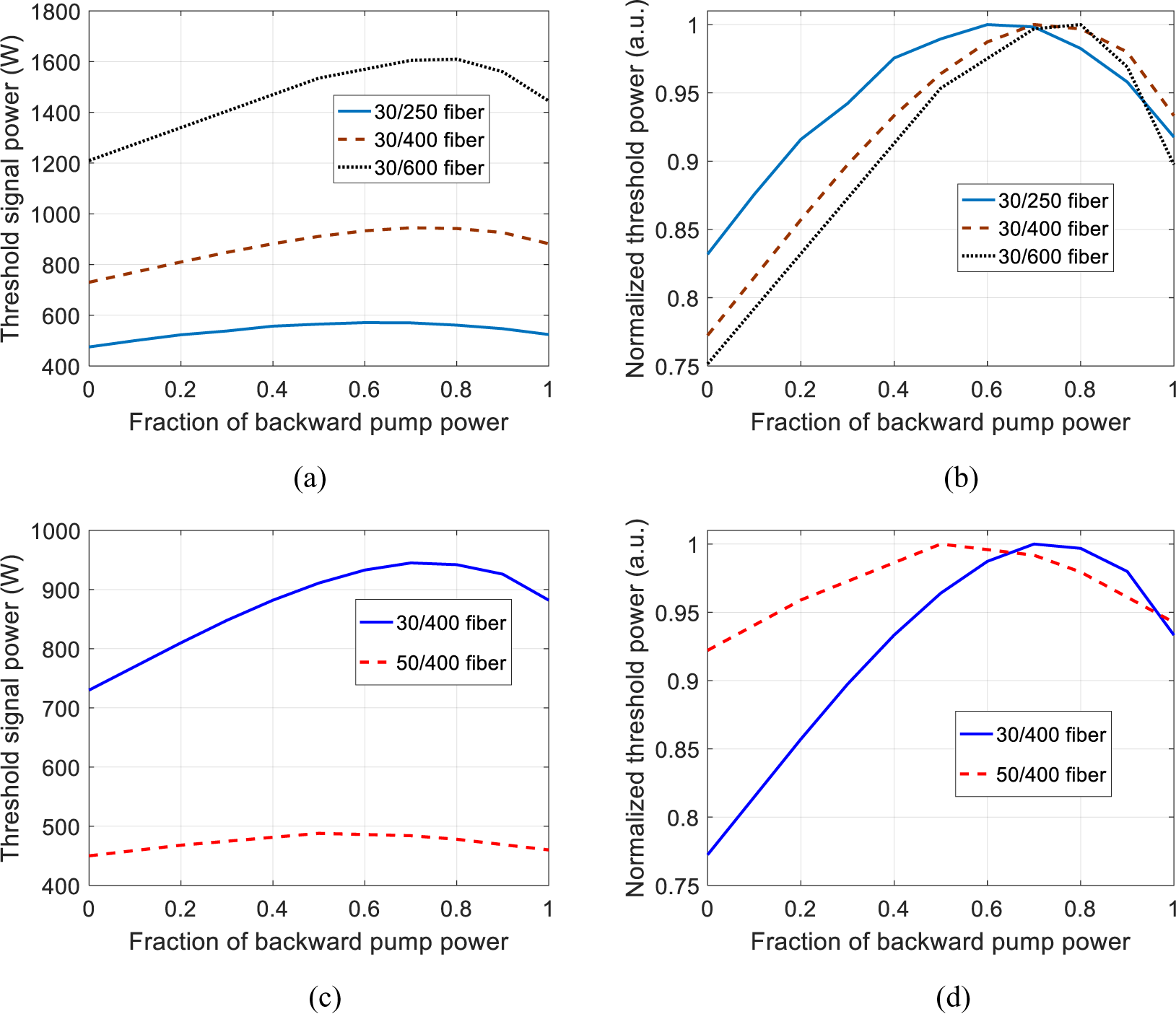
The mode instability threshold as a function of backward pump power fraction for DSCCP fiber with different types of signal fiber with k = 2 m–1 is shown in Figure 9. Here, N Yb = 1.3 × 1025 m–3 and the length of the fiber was set to ensure that the unabsorbed or residual pump power in the pump core is about 5%. The other parameters are the same as those in Figure 8. It revealed that, for the same core size, the maximal threshold increment for signal fiber with signal cladding being 600/400/250 μm is about 34%/23%/16%, and the maximal threshold increment for signal fiber with signal cladding being 30/50 μm is about 16%/8%, which means that the maximal threshold increment is larger for signal fiber with a larger cladding size or smaller core size. This is because the hole burning is stronger for a larger signal cladding size or smaller core size[ Reference Tao, Wang, Zhou and Liu 42 , Reference Smith and Smith 51 ]. One can also see that the optimal backward pump power fraction for fiber with signal cladding being 250/400/600 μm is 0.6/0.7/0.8, and that for fiber with the signal core being 30/50 μm is 0.5/0.6, which reveals that the optimal backward pump power fraction reduces as the signal cladding size reduces or the signal core size increases. One can conclude that the optimal backward pump power fraction is related to the hole burning effect in the fiber.
(a) Threshold signal power as a function of backward pump power fraction for different cladding sizes. (b) Normalized threshold signal power as a function of backward pump power fraction for different cladding sizes. (c) Threshold signal power as a function of backward pump power fraction for different core sizes. (d) Normalized threshold signal power as a function of backward pump power fraction for different core sizes.
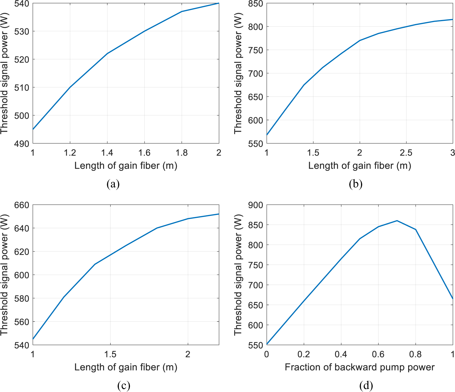
The mode instability threshold dependence on the fiber length has been studied for co-pumped end-coupled amplifiers[ Reference Tao, Wang and Zhou 8 ], but there are no reports on counter-pumped or bi-direction-pumped ones. To investigate the fiber length behavior, the mode instability threshold as a function of fiber length is studied in Figure 10. Figures 10(a)–10(c) show that the mode instability threshold increases as the length of the gain fiber increases, and gradually approaches a constant value. One can see that the length where the mode instability reaches an asymptotic value is different. The length for bi-direction pumping schemes is longer than those for uni-direction pumping schemes, which means that, for bi-direction pumping schemes, the gain fiber should be longer than those in uni-direction pumping schemes to further suppress mode instability. When the length of the gain fiber is taken to be 3 m, the mode instability threshold as a function of backward pump power fraction is as shown in Figure 10(d), which reveals that, compared with forward pumping schemes, the mode instability can be increased by 56% for the optimal bi-direction pumping case (with the fraction of backward pump power being 0.7). This is significantly higher than those in Figure 8, which can explain the deviation between Refs. [Reference Tao, Ma, Wang, Zhou and Liu31, Reference Yu, Shatrovoy, Fan and Taunay60]: the mode instability for the bi-direction pumping case is nearly doubled in Ref. [Reference Jauregui, Eidam, Limpert and Tünnermann48] and outperforms the predicted results in Ref. [Reference Tao, Ma, Wang, Zhou and Liu31]. In Ref. [Reference Yu, Shatrovoy, Fan and Taunay60], total pump absorption of 20 dB was employed, whereas that in Ref. [Reference Tao, Ma, Wang, Zhou and Liu31] is about 13 dB.
(a) Threshold signal power as a function of fiber length for backward pump power fraction of 0 corresponding to the co-pumping scheme. (b) Backward pump power fraction of 0.5 corresponding to the bi-directional-pumping scheme. (c) Backward pump power fraction of 1 corresponding to the counter-pumping scheme. (d) Threshold signal power as a function of the backward pump power fraction.
The threshold as a function of various averaged coupling coefficients is shown in Figure 11, where the simulation parameters are the same as in Figure 10 except for N Yb = 2 × 1026 m–3, which has been increased to shorten the fiber length and calculation time. To ensure comparability, the remaining pump power in the pump core is 5% for all cases. It is shown in Figure 9(a) that, as the coupling coefficient increases, the mode instability threshold reduces while the length of the fiber to ensure efficient pump absorption reduces. This is because the pump power coupling to signal cladding is faster for larger coupling coefficients, which causes the results that the pump power in signal cladding is higher for larger k, and the hole burning effect is weaker. The hole burning effect tends to suppress mode instability, so the mode instability threshold reduces as k increases. As the radius and refractive index of the signal and pump fibers may be different, the coupling coefficient k 1 is not equal to k 2 [ Reference Huang, Cao, Guo, Hou and Chen 27 ], and cases with different coupling coefficients should be studied. The threshold as a function of various coupling coefficient ratios k 1/k 2 (k 1 = 10) is shown in Figure 11(b). It is revealed that the mode instability threshold reduces as the coupling coefficient ratio k 1 increases. This is because, as k 1 increases and/or k 2 reduces, the pump power in signal cladding is higher and the hole burning effect is also weaker.
Threshold signal power as a function of coupling coefficient.

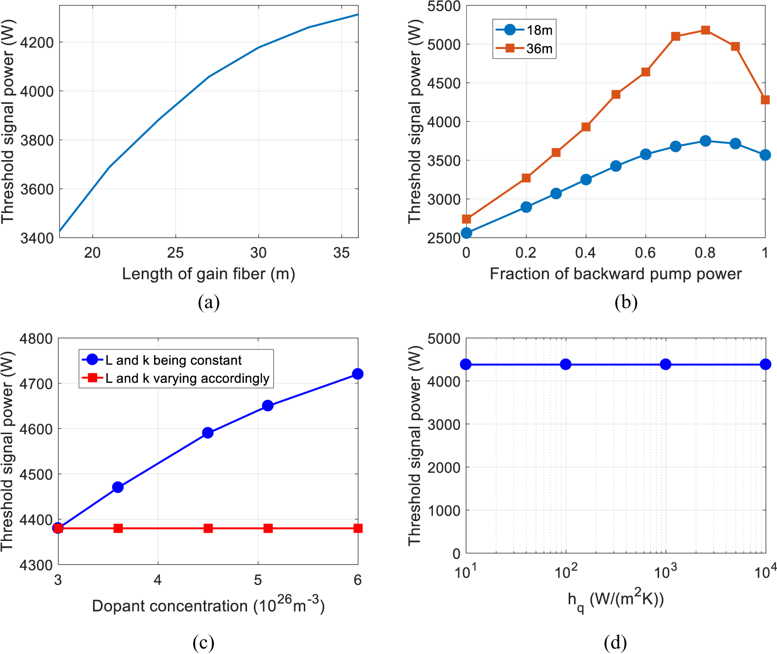
Tandem pumping technology can increase the gain saturation and reduce the quantum defect, which tends to suppress mode instability[ Reference Tao, Wang and Zhou 8 ]; the mode instability of DSSSP fiber employing tandem pumping technology is shown in Figure 12. For the tandem pumping case, a fiber laser operating at 1018 nm can achieve higher laser power, and high-power tandem pumped fiber laser systems often operate at 1080 nm for suppressing stimulated Raman scattering (SRS) by reducing the Yb-gain of Raman light[ Reference Zhou, Xiao, Leng, Xu, Chen, Zhang and Liu 61 , Reference Zhang, Zhou, Xiao, Leng, Tao, Wang, Xu, Xu and Liu 62 ]. Thus, the signal wavelength and the pump wavelength are set to be 1080 and 1018 nm, respectively. For multi-kilowatt operation and longer gain fiber, higher seed powers are required to avoid unwanted amplified spontaneous emission, and the initial signal power is set to be 166 W according to the experiment[ Reference Tao, Xiao, Zhang, Leng, Wang, Zhou and Xu 63 ]. As the pump absorption cross-section at 1018 nm is one order of magnitude smaller than those for conventional direct diode pumping at 9xx nm, the dopant concentrations have been set to about N Yb = 3 × 1026 m–3 to shorten the fiber length. Other parameters are the same as those in Table 1. It is revealed from Figure 12(a) that when the fiber length increases from 18 to 36 m, the signal power threshold increases from 3.4 to 4.3 kW. From Figure 12(b), one can see that, when the length of the gain fiber is taken to be 36 m, the mode instability can be increased by 89% for the optimal bi-direction pumping case (with the fraction of backward pump power being 0.8), which is higher than those with a shorter fiber length (46.5%). This is because the heat load reduces as fiber length increases, which tends to increase the mode instability[ Reference Jauregui, Stihler and Limpert 9 ]. The threshold signal power as a function of dopant concentration is shown in Figure 12(c), where L is 36 m and the amplifier is bi-directional pumped with an even pump power fraction. The other parameters are the same as those in Figure 12(a). It is revealed that the doping concentration increase has the same effect as the fiber length increase, and tends to increase the mode instability. However, if the length of the fiber L and the coupling coefficient k are varied accordingly, the mode instability threshold remains constant as the dopant concentration increases. For multi-kilowatt operation, water cooling of the gain fiber has been employed to keep the fiber operating at a safe temperature, but there is little impact on the mode instability, as indicated in Figure 12(d), which agrees with the results in Ref. [Reference Hansen, Alkeskjold, Broeng and Lægsgaard52].
(a) Threshold signal power as a function of fiber length for backward pump power fraction of 0.5. (b) Threshold signal power as a function of the backward pump power fraction for different fiber lengths. (c) Threshold signal power as a function of dopant concentration. (d) Threshold signal power as a function of the convection coefficient.
3.3 Dynamic mode instability in two-pump-core DSCCP fiber amplifiers
DSCCP fibers with more pump cores are also of interest to create high-power fiber lasers and amplifiers[ Reference Bochkov and Slobozhanina 29 , Reference Zhan, Liu, Wang, Ke, Ni, Wang, Peng, Gao, Li, Lin, Wang, Jing and Lin 34 , Reference Du, Cao, Huang and Chen 64 ], which can naturally increase the number of injection points of the pump radiation. The maximal pump core number is less than π(1 + R/R pump), where R is the radius of the signal fiber pump cladding and R pump is the radius of the pump fiber. If the pump cores are in contact with the signal fiber and without contact with each other (the schematic diagram of DSCCP fiber with two without-contact inner claddings is shown in Figure 13), the transversally resolved steady-state rate equations should be modified, and additional differential equations should be added to take every pump core into consideration.
For DSCCP fiber with more without-contact pump cores, the transversally resolved steady-state rate equations should be expressed as
 \begin{align}\frac{\mathrm{d}{P}_{\mathrm{p}\mathrm{p}i}^{\pm}\left(z,t\right)}{\mathrm{d}z}=- {k}_1{P}_{\mathrm{p}\mathrm{p}i}^{\pm}\left(z,t\right)+{k}_2{P}_{\mathrm{p}}^{\pm}\left(z,t\right),\end{align}
 \begin{align}&\frac{\mathrm{d}{P}_{\mathrm{p}}^{\pm}\left(z,t\right)}{\mathrm{d}z}=\frac{P_{\mathrm{p}}^{\pm}\left(z,t\right)}{A_{\mathrm{p}}}\int \int \left[\left({\sigma}_{\mathrm{p}}^{\mathrm{a}}+{\sigma}_{\mathrm{p}}^{\mathrm{e}}\right){n}_{\mathrm{u}}\left(r,\phi, z,t\right)-{\sigma}_{\mathrm{p}}^{\mathrm{a}}\right]\notag\\&\enspace\times{N}_{\mathrm{Yb}}\left(r,\phi \right)r\;\mathrm{d}\phi\;\mathrm{d}r+{k}_1\sum \limits_i{P}_{\mathrm{p}\mathrm{p}i}^{\pm}\left(z,t\right)-2{k}_2{P}_{\mathrm{p}}^{\pm}\left(z,t\right),\end{align}
Schematic diagram of DSCCP fiber with two without-contact inner claddings.
where ${P}_{\mathrm{p}\mathrm{p}i}^{+}$
and
${P}_{\mathrm{p}\mathrm{p}i}^{+}$
and ${P}_{\mathrm{p}\mathrm{p}i}^{-}$
represent the forward and backward pump power in the ith pump core, respectively, and the meanings of the other symbols are the same as those in Section 2. Substituting Equation (6) into the model in Section 2, one can calculate the mode instability threshold for DSCCP fiber with more without-contact pump cores through Equations (4) and (5).
${P}_{\mathrm{p}\mathrm{p}i}^{-}$
represent the forward and backward pump power in the ith pump core, respectively, and the meanings of the other symbols are the same as those in Section 2. Substituting Equation (6) into the model in Section 2, one can calculate the mode instability threshold for DSCCP fiber with more without-contact pump cores through Equations (4) and (5).
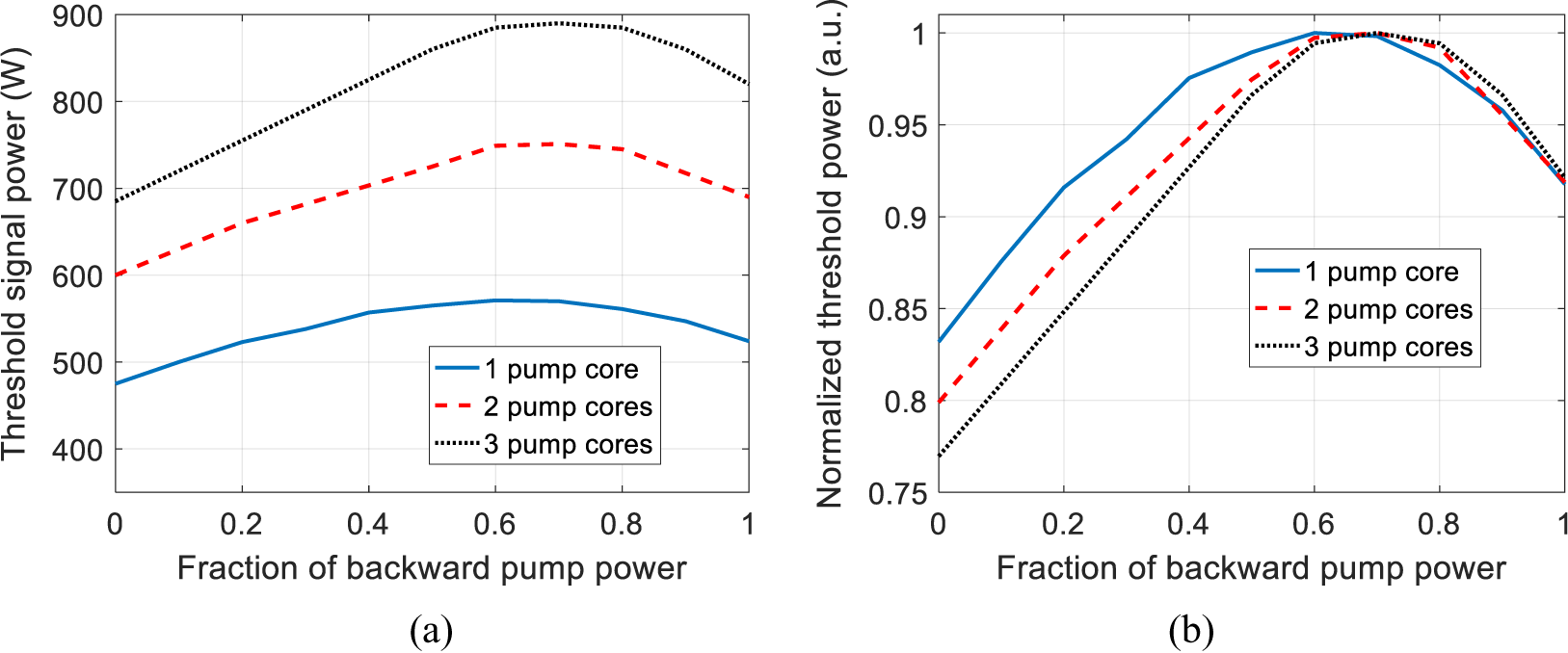
Threshold signal power as a function of the backward pump power fraction for different pump cores has been calculated, as shown in Figure 14, and the normalized data are also given for the convenience of comparison. The parameters are the same as those used in Figure 8. The DSCCP fiber is evenly bi-direction pumped with the backward pumping power fraction being 0.5 for both pump ports, and the total pump power in pump core 2 is equal to that in pump core 1. For DSCCP fiber with two without-contact pump cores, the signal power threshold is 727 W, which is 27% higher than those with only one pump core. For DSCCP fiber with three without-contact pump cores, the signal power threshold can be further increased to about 845 W, which is approximately 16% higher than those with two pump cores. One can conclude that the mode instability threshold can be increased by increasing the number of the pump cores. This is because the pump power coupling into the signal cladding is slower, which results in the pump power in the signal cladding being flatter and the hole burning effect being stronger. One can also find that the threshold increment becomes less as the number of pump cores increases. This is because as the number of pump cores increases, the flattening of the pump power in signal cladding becomes less evident, which means that the mode instability threshold cannot be increased unlimitedly by increasing the number of pump cores.
(a) Threshold signal power and (b) normalized threshold signal power as a function of the backward pump power fraction for different pump cores.
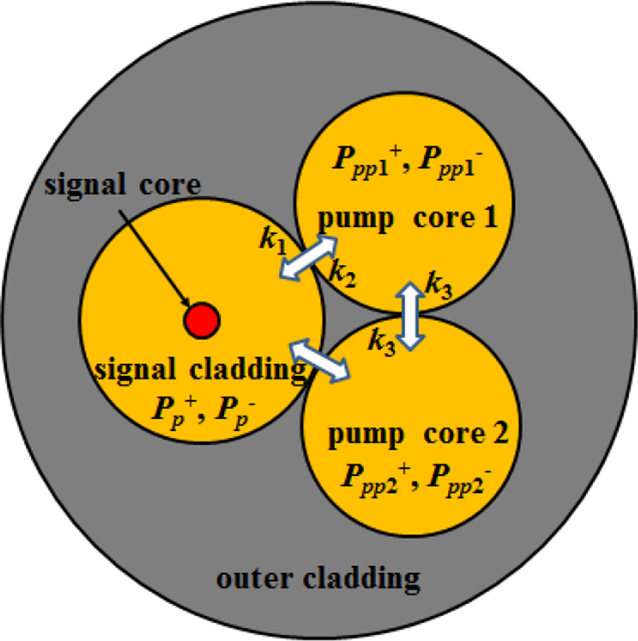
Another case is that in which the pump cores are optically in contact with each other; Figure 15 shows the schematic diagram of DSCCP fiber with two in-contact pump cores. Compared with DSCCP fiber with without-contact pump cores, the pump core is in touch with the other pump cores. In this configuration, there exists an additional power coupling process between the pump cores, which is characterized by k 3.
Schematic diagram of distributed side-coupled cladding-pumped fiber with two in-contact pump cores.
To study the mode instability in DSCCP fiber with two in-contact pump cores, the transversally resolved steady-state rate Equations (3b)–(3d) should be changed to take the power transmission between the two pump cores into account, which can be expressed as
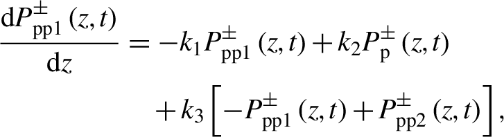 \begin{align}\frac{\mathrm{d}{P}_{\mathrm{p}\mathrm{p}1}^{\pm}\left(z,t\right)}{\mathrm{d}z}&=- {k}_1{P}_{\mathrm{p}\mathrm{p}1}^{\pm}\left(z,t\right)+{k}_2{P}_{\mathrm{p}}^{\pm}\left(z,t\right)\notag\\&\quad+{k}_3\left[- {P}_{\mathrm{p}\mathrm{p}1}^{\pm}\left(z,t\right)+{P}_{\mathrm{p}\mathrm{p}2}^{\pm}\left(z,t\right)\right],\end{align}
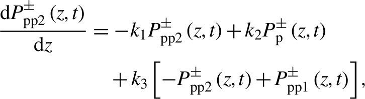 \begin{align}\frac{\mathrm{d}{P}_{\mathrm{p}\mathrm{p}2}^{\pm}\left(z,t\right)}{\mathrm{d}z}&=-{k}_1{P}_{\mathrm{p}\mathrm{p}2}^{\pm}\left(z,t\right)+{k}_2{P}_{\mathrm{p}}^{\pm}\left(z,t\right)\nonumber\\&\quad{}+{k}_3\left[- {P}_{\mathrm{p}\mathrm{p}2}^{\pm}\left(z,t\right)+{P}_{\mathrm{p}\mathrm{p}1}^{\pm}\left(z,t\right)\right],\end{align}
 \begin{align}\frac{\mathrm{d}{P}_{\mathrm{p}}^{\pm}\left(z,t\right)}{\mathrm{d}z}&=\frac{P_{\mathrm{p}}^{\pm}\left(z,t\right)}{A_{\mathrm{p}}}\int \int \left[\left({\sigma}_{\mathrm{p}}^{\mathrm{a}}+{\sigma}_{\mathrm{p}}^{\mathrm{e}}\right){n}_{\mathrm{u}}\left(r,\phi, z,t\right)-{\sigma}_{\mathrm{p}}^{\mathrm{a}}\right]\notag\\&\quad\times {N}_{\mathrm{Yb}}\left(r,\phi \right)r\;\mathrm{d}\phi\;\mathrm{d}r\notag\\&\quad{}+{k}_1{P}_{\mathrm{p}\mathrm{p}1}^{\pm}\left(z,t\right)+{k}_1{P}_{\mathrm{p}\mathrm{p}2}^{\pm}\left(z,t\right)-2{k}_2{P}_{\mathrm{p}}^{\pm} \left(z,t\right),\end{align}
where k 3 is the averaged coupling coefficient of the pump light between pump core 1 and pump core 2, and the meanings of the other symbols are the same as those in Section 2. Substituting Equation (7) into the model in Section 2, one can calculate the mode instability threshold for DSCCP fiber with two in-contact pump cores through Equations (4) and (5).
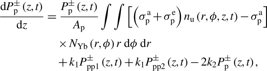
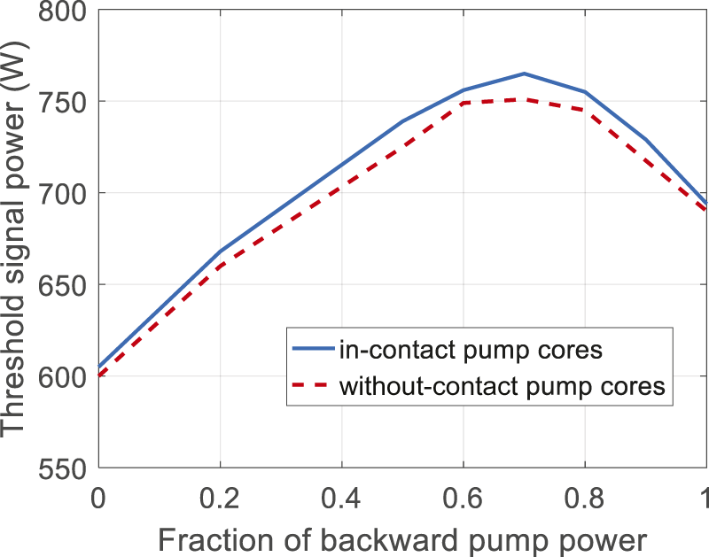
Threshold signal power as a function of the backward pump power fraction for two in-contact pump cores has been calculated, which is shown in Figure 16. The length of the fiber is taken to be 1.6 m to ensure that only 5% pump power is left in the pump core, k 3 is 10 m–1 and the other parameters are the same as those in Table 1. The total pump power in pump core 1 is equal to that in pump core 2. It is shown that, compared with that for DSCCP fiber with two without-contact pump cores, the mode instability is slightly higher (2%) for DSCCP fiber with two in-contact claddings. This is because the coupling process between the two pump cores slightly reduces the speed of the pump power coupling into the signal cladding, which tends to increase the hole burning and suppress the mode instability. The results for different k 3 and fiber length are listed in Table 2, where the amplifier is bi-direction pumped with the backward pumping power fraction being 0.5 for both pump ports. One can find that, when the fiber length is increased to 3 m, the mode instability is further increased to approximately 920 W. However, the mode instability threshold is nearly independent of the coupling coefficient k 3, which is because the power distribution along the fiber is almost unchanged when coupling coefficient k 3 varies and the hole burning effect is nearly the same.
Threshold signal power as a function of the backward pump power fraction.
Mode instability threshold of DSCCP fiber with two in-contact pump cores.
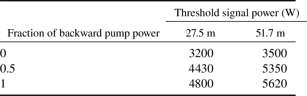
By employing the tandem pumping technology, the mode instability threshold is as listed in Table 3. For two in-contact pump cores, k 1 = k 2 = k 3 is set to 2 m–1, and the other parameters are the same as those in Figure 8. One can see that the maximal signal power can be increased to above 4.8 and 5.6 kW for 27.5 and 51.7 m, respectively. Although mode-instability-free 5.6 kW can be achieved for 51.7 m, the length of the fiber is longer compared with generally employed fiber lengths, which can trigger the onset of other nonlinear effects, such as stimulated Brillouin scattering (SBS), SRS and four-wave mixing. As mentioned at the start of this section, the dopant concentration and coupling coefficient can be increased in a certain relation to shorten the required fiber length with little impact on the mode instability threshold, and it is shown that a higher concentration is achievable with acceptable photodarkening through proper co-dopant content and manufacturing craft[ Reference Ye, Petit, Koponen, Hu and Galvanauskas 58 , Reference Tammela, Söderlund, Koponen, Philippov and Stenius 65 ]. In addition, DSCCP fiber is naturally resistant to nonlinear effects[ Reference Chen, Cao, Huang, Ren, Wang and Chen 66 ], techniques to mitigate the aforementioned nonlinear effects are relatively mature and various techniques, including material content optimization, can be employed to suppress these detrimental effects[ Reference Kobyakov, Sauer and Chowdhury 67 – Reference Dragic, Cavillon, Ballato and Ballato 71 ].
Mode instability threshold of DSCCP fiber with two in-contact pump cores.
As the mode instability model has not taken the influence of linewidth into consideration, the achieved results are accurate for narrow linewidth models[ Reference Tao, Wang and Zhou 8 ]. For the case in which the spectral linewidth is broad, the influence of linewidth on the de-coherence of mode interference cannot be ignored, which can increase the threshold of mode instability[ Reference Smith and Smith 72 – Reference Alekseev, Tyrtyshnyy, Kuznetsov and Antipov 74 ]. Comparing the tandem pumped results in Refs. [Reference Tao, Xiao, Zhang, Leng, Wang, Zhou and Xu63, Reference Ma, Xiao, Meng, Liu, Tao, Leng, Ma, Su, Zhou and Liu75], one can see that the mode instability threshold has been nearly doubled due to linewidth broadening, which means that the mode instability threshold for broad spectral bandwidths can be reasonably estimated to be beyond 10 kW. One can conclude that a more than 5 kW narrow linewidth or a more than 10 kW broadband single mode fiber laser can be achieved in DSCCP fiber in conjunction with the tandem pumping technique, only if a high dopant concentration can be achieved. It is shown in Refs. [Reference Liu, Cao and Chen76, Reference Dong77] that a thermal-lens can induce static mode coupling and increase the mode instability threshold, but the thermal-lens effect is obvious and stronger in larger diameter fibers. For fibers with a core diameter smaller than 30 μm, which is generally the case in high average power fiber laser systems, the LP11 mode is reasonably well confined and not overly sensitive to thermal perturbations, which means that this effect can be neglected[ Reference Laegsgaard 78 , Reference Xia and Yoo 79 ].
4 Conclusions
In summary, based on a modified semi-analytical model of mode evolution, static and dynamic mode evolution behaviors in high-power DSCCP fiber amplifiers have been investigated for the first time. It is revealed that DSCCP fiber amplifiers suffer severer static mode degradation, while the mode instability thresholds for DSCCP fiber amplifiers are 40% higher than those of the ECCP fiber amplifiers, which means that the DSCCP fiber has an advantage over ECCP fiber in the aspect of suppressing mode instability. By increasing the number of the pump cores and reducing the averaged coupling coefficient, the mode instability threshold can be increased. The power coupling between pump cores can also facilitate the suppression of mode instability. Experimental study will be designed and carried out in the near future to further demonstrate the theoretical results.
Acknowledgment
This work was funded by the National Natural Science Foundation of China (NSFC) (61905226) and the Youth Talent Climbing Foundation of the Research Center of Laser Fusion. The authors would like to thank their colleagues at Fiber Laser Research Center of the Research Center of Laser Fusion for constant support and helpful discussions. The first author acknowledges the helpful discussion of Xiaolin Wang.


 Open access