


Introduction
Multipactor breakdown is an avalanche-like electron discharge occurring in components operating under certain vacuum conditions and high-power radio frequency (RF) electromagnetic fields [Reference Farnsworth1]. This phenomenon, which is particularly detrimental for satellite payloads, occurs when free electrons in the device become synchronized with the RF electric field and hit a metallic wall of the component with enough energy to release secondary electrons from the surface. The increasing number of electrons in the device can lead to one or more discharges, which can have several negative effects that diminish component performance or, worse, run the risk of shutting down the RF downlink of a satellite's communications [Reference Chang, Lawless and Yamamoto2, Reference Vaughan3]. The current trend is to increase the RF power in the payload equipment to satisfy growing customer demand and needs in terms of data rate. Filters or multiplexers located at the Tx part of the payload and channeling high power levels are particularly sensitive to multipactor effect. For several years, multipactor effect has been a central concern in the design of filters dedicated to space applications [Reference González, García-Baquero, Ernst, Schmitt, Boria Esbert, Gimeno Martínez, Taroncher Calduch and Quiles4]. It should be remembered that the transmission (Tx) and receiving (Rx) paths of the payload, designate the output and the input, respectively, of the payload of the satellite and have very different power levels: high for the Tx and low for the Rx.
For these reasons, and also because they need high quality factors, these (Tx) components are mainly designed with volumic resonators. Rectangular or cylindrical waveguides are the most common choice when high quality factors are required. Due to their large dimensions, they make it possible to reach very large quality factors, of tens of thousands, and high multipactor thresholds. For instance, in Ku band at 14.375 GHz, with silvered cylindrical resonators (conductivity 61 MS/m), it is possible to obtain theoretical quality factors of around 25 000 and for the multipactor threshold to reach 7000 W. These values are obtained in TE011 mode, with a method similar to [Reference Atia and Williams5], by choosing a diameter to length ratio of 1.39, making it possible to reject the TE211 and TE311 neighbor modes sufficiently. Under these conditions, the length and diameter are 21.06 and 29.28 mm, respectively. For L-band applications, therefore, it is clear that such volumic solutions, whether cylindrical or rectangular, would be too bulky. Moreover, if only lower quality factors, of around 5000, are needed, these solutions are definitively inappropriate.
In this case, other topologies based on transverse electromagnetic mode (TEM) coaxial configurations can be advantageous [6]. A coaxial waveguide has degrees of freedom on its transverse dimensions, making it possible to reach the requested quality factor. The drawback is that the longitudinal dimension, which is inversely proportional to the frequency, is fixed and can be a crippling constraint. To overcome this problem, the structure can be reentrant [Reference Wang and Zaki7, Reference Wu, Mansour and Wang8] or simply folded on itself. Moreover, it is possible to take advantage of a stepped impedance coaxial resonator (SIR)[Reference Makimoto and Yamashita9] effect appearing in the folded structure to modulate the size reduction. This principle provided an original concept for a resonator, the SIR coaxial resonator [Reference Belyaev, Serzhantov, Tyurnev and Leksikov10–Reference Aouidad, Rius, Favennec, Manchec and Clavet12], built from coaxial structures fitted inside one another. The main particularity of this resonator is its construction out of a succession of coaxial sections in cascade, where the ground conductor of one becomes the central core of the next, or vice-versa. In terms of design, this geometric construction offers several degrees of freedom, making it possible to choose the best trade-off between all the required specifications. The originality lies in the fact, that these degrees of freedom, which make it possible to modulate the transversal and vertical dimensions of the resonator separately, allow the filter performances to be precisely adjusted as needed in terms of size, quality factor, and multipactor threshold.
To show the potential of this topology, this paper presents an example of the design of an L-band Tx filter, for an industrial application. In the Section “Specifications of the L-band filter,” we present the requested specifications, the main challenge being to simultaneously satisfy the requirements in terms of size, electrical performances, and power handling. Considering these specifications, we show how a first analysis allowed us to define the order of the filter and, consequently, the size of the elementary resonator according to an optimization/numerical procedure described in [Reference Hallet, Favennec, Rius, Bénédicto, Carpentier and Pacaud13]. In the Section “Multipactor threshold evaluation,” we analyze the behavior of the resonator in terms of multipactor threshold, the goal being to find the best configuration without modifying the size, previously established in the Section “Specifications of the L-band filter.” In the Sections “Design of the L-band filter” and “Fabrication and RF measurements of the L-band filter,” we present the design, manufacturing, and RF measurements of the whole structure. This is a sixth-order, cross-coupled filter, able to support a maximum RF power of 400 W and satisfy all the other requirements. The last section, “Multipactor measurements,” is devoted to the multipactor measurements, carried out on a specific test bench. Finally, we present our conclusions on this study.
Specifications of the L-band filter
Specifications and preliminary evaluation of the main filter parameters
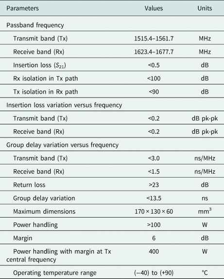
In this section, we present the required specifications (Table 1). These concern an L-band duplexer, intended to equip the payload of a new-generation Global Navigation Satellite System (GNSS) satellite.
Table 1. Specifications of the L-band duplexer

As the Rx part of the duplexer is not concerned by the RF power handling, we focused only on the Tx part, for which it is reasonable to reserve at least ~70% of the whole available volume. The requested isolation between the Rx and the Tx parts, which is 90 dB, forced us to choose an eight-order Chebyshev electrical response. To minimize the number of resonators, which optimizes size economy, quality factor, and multipactor threshold, a sixth-order cross-coupled electrical response presenting transmission zeros was chosen. Under these conditions, the requested insertion losses and flatness in the passband gave a quality factor of around 4000. By considering a sixth-order filter in a volume of around 70% of that given by the specification, built on a footprint equal to 170 mm × 130 mm and a thickness of 40 mm, with metallic walls of 4 mm, the RF envelope of each elementary resonator will be around 51.2 mm × 51.2 mm × 32 mm.
At 1.5 GHz, the quarter wavelength in air is 50 mm, meaning that the length of a uniform coaxial resonator is too large to fit into the available volume. Therefore, to decrease these dimensions, we decided to design the filter based on SIR coaxial resonators.
SIR coaxial resonator and design methodology
An SIR coaxial resonator with two sections presented in Fig. 1 offers several degrees of freedom [Reference Aouidad, Favennec, Rius and Manchec14]. It consists of two cylindrical conductors C 1 and C 2, embedded in a rectangular metallic box C 3. The structure is first composed of three transmission lines of respective characteristic impedances and lengths (Z 1, l 1), (Z 2, l 2), and (Z 3, l 3).

Fig. 1. SIR coaxial resonator: (a) 3D-exploded view, (b) front view, cross-section, and (c) top view, cross-section.
The characteristic impedances of each coaxial line supporting a TEM mode can be expressed as follows:

where η 0 and ɛr are the vacuum impedance and the relative dielectric constant of the material, respectively [Reference Vizmuller15, Reference Omar and Miller16]. Rext and Rint are the outer and inner radii of the conductors, respectively. The parameter s is equal to 1 for an external circular section, and equal to 1.079 for a square section. The TEM signal propagation undergoes two SIR effects, characterized by the ratios M 12 and M 23 of the characteristic impedances, calculated as:

To model the resonator correctly, several discontinuity effects also need to be considered at the open and shorted ends of each cylinder. Although the parasitic inductances at the shorted extremities of the cylinders can be ignored, it is vital to take one of the capacitive effects at the open extremities into account. This capacitance is located at the open end of cylinder C 1 and is fully described in [Reference Atia and Williams5].
The geometric characteristics of this resonator were chosen according to a numerical procedure described in [Reference Hallet, Favennec, Rius, Bénédicto, Carpentier and Pacaud13]. This iterative procedure makes it possible to minimize the volume for a given quality factor, resonance frequency, and square footprint, which were fixed at 4000, 1.5 GHz, and 51.2 mm × 51.2 mm, respectively.
Due to the relation between the characteristic impedance ratios M on the resonant frequency, the transversal dimensions (r 1, R 1, r 2, and R 2), and the lengths (l 1, l 2, and l 3) are linked together. If the radius r 1 of the cylinder C 1, the thickness of the cylinder C 2 (ec 1 = r 2 − R 1) and length l 2 are fixed, it is possible to obtain many pairwise combinations of (r 2, l 3, l t, and d 1) and (f 0, Q, and V), characterized by different multipactor threshold values.
Multipactor threshold evaluation
Simplified simulation model for multipactor threshold evaluation
To simplify the study of the impact of resonator geometry on multipactor threshold, the study was conducted on a second-order filter (Fig. 2) built based on the resonator defined in the previous section. Indeed, the evaluation of multipactor threshold, with Spark3d [17] requires the analysis of a correctly matched filtering response. To save time, working with a limited order is preferable.

Fig. 2. Example of a two-section second-order filter with SIR coaxial resonators: (a) 3D-exploded view, (b) front view 1, cross-section, and (c) front view 2, cross-section.
For this, once the electromagnetic simulation of the filter (S parameters; electrical field) with HFSS is done, the electromagnetic fields are exported to Spark3d which calculates the multipactor threshold.
Spark3d is partly based on a Monte Carlo statistical approach. The types of interactions (elastic backscattering, inelastic backscattering, and real secondary electrons) are distinguished according to the Vaughan model [Reference Gonzales-Iglesisas, Monerris, Gimeno, Díaz, Boria, Martin, Gomez Gomez, Fernandez, Vegas, Casas, Anza, Vicente, Gil, Mata, Montero and Raboso18, Reference Vicente, Mattes, Wolk, Hartnagel, Mosig and Raboso19].
In order to function, Spark3d needs to know the secondary emission yield (SEY) characteristic of the material. It is possible to use predefined material but also to define one's own model by setting the following characteristics: the maximum secondary emission coefficient (δ), electron energy at maximum SEY (Em), and lower crossover electron energy (E 1). Results on the variation of these parameters are highly sensitive. For instance, varying E 1 and δ from 50 to 45 eV and from 2.2 to 2, respectively, increases the multipactor threshold by about 5 dB. It must be underlined that the variation of E 1 particularly impacts parallel-plate like structures. The other settings are the power test interval and the number of primary electrons.
For this simplified filter, the center frequency, relative bandwidth, and matching level were set at 1.537 GHz, 2%, and 20 dB, respectively. The material considered was silver (ECSS [20]).
Method
Multipactor effect depends on a large number of parameters, such as the resonant frequency, the material in which the filter is fabricated [20], the geometry and, particularly, the distance between the two metallic elements [Reference Vaughan3, Reference Vicente, Mattes, Wolk, Mottet, Hartnagel, Mosig and Raboso21].
In our case, as the center frequency and material were fixed, we focused only on the impact of the distance between two metallic conductors. Considering the topology, the areas that required careful observation were those between the two cylinders, and the cylinder C 2 and the rectangular box.
We can distinguish three critical zones, or three critical distances, separating two metallic conductors:
• ring width d 1 = R 1 − r 1 separating the first cylinder C 1 and the second cylinder C 2;
• ring width d 2 = R 2 − r 2 between the second cylinder C 2 and the square metallic box C 3; and
• distance d 3 = l 2 between the first cylinder C 1 and the metal box C 3, and between the second cylinder C 2 and the metal box C 3.
These three dimensions can greatly modify the value of the multipactor threshold. The variable d, defined as d = min{d 1, d 2, d 3}, is the minimum value among these three quantities. Thus, for a frequency fixed, the distance d is considered as the most critical dimension for the multipactor phenomenon. As the footprint of the resonator was fixed, d 2 decreased when d 1 increased, and vice versa.
To overcome the multipactor effect at the open ends of cylinders C 1 and C 2, the variable d 3, which is independent of these two quantities (d 1 and d 2), was fixed at 9 mm.
Fifteen versions of the filter were tested, simulated, and optimized, all with the same center frequency, relative bandwidth, external section R 2, radius of the internal cylinder r 1, and length l 2. For each simulation, d 1 (d 2) was the variable, varying from 1 to 15 mm (18 to 4 mm). It is important to specify that the SIR effect was modified for each new value of d 1, which implied readjusting the total length lt of the resonator to keep the center frequency constant. An example of an electrical response of the filter, with d 1 = 8 mm is presented in Fig. 3. Once all the simulations had been carried out with a correctly matched filter, the value of the multipactor threshold could be plotted as a function of the ring width d 1, with a fixed central frequency f 0 of the filter equal to 1.537 GHz (Fig. 4). From this curve, we could extract an analytical model of the evolution of the multipactor threshold as a function of ring width d 1. According to the value of d 1, two different behaviors were observed. For d 1 ≤ 10 mm, the multipactor threshold evolution was defined by


Fig. 3. Electrical response of the simplified filter (d 1 = 8 mm).

Fig. 4. Multipactor threshold plotted on ring width d 1 (distance between internal cylinder C 1 and external cylinder C 2) for a constant resonant frequency.
In this range of variation, the minimum value among the three quantities d = min{d 1, d 2, d 3} was d 1. Therefore, the minimum value d increased continuously (with the value d 1) and the multipactor threshold also increased. For d 1 ≥ 10 mm, the behavior of the multipactor threshold changes because the minimum value among the three quantities {d 1, d 2, d 3} is d 2; in this case d 2 ≤ 9 mm. As mentioned earlier, in order to maintain the same central frequency and relative bandwidth for each filter, it is necessary to adjust the total length lt which increases with d 1. Therefore, changing the ring width d 1 will modify: the multipactor threshold, the volume of each resonator, and the quality factor. Figure 5 shows the evolution of the length lt and of the quality factor Q as a function of the ring width d 1 separating the two cylindrical conductors. The quality factor, calculated in eigenmode with HFSS, decreased for values of d 1 higher than 4 mm, but remained greater than 4000 for a wide range of d 1.

Fig. 5. Quality factor and length lt plotted on ring width d 1, for a constant resonant frequency.
The length of the resonator increased continuously, but remained below 40 mm. The simulation results showed that to optimize the multipactor threshold behavior in this second-order filter (>250 W), with a low volume and a high quality factor, it would be necessary to respect a minimum distance of 9 or 10 mm for all the values (d 1, d 2, d 3).
This result was integrated as a constraint in the design of the sixth-order cross-coupled filter, presented in the next section.
Design of the L-band filter
Design of the elementary resonator
The geometric parameters of an elementary SIR coaxial resonator, presented in Table 2, were obtained by the optimization procedure mentioned in the previous section, to which a constraint on the multipactor threshold was added. It should be remembered that the footprint of the resonator is fixed. The values of the resonant frequency and quality factor were validated electromagnetically with HFSS (Table 2).
Table 2. Geometric and electrical parameters of the SIR coaxial resonator

Design of the filter
Once the resonator was defined, the sixth-order filter could be designed (Fig. 6). A study based on Zabalawi synthesis [Reference Matthaei, Young and Jones22, Reference Zabalawi23] provided the coupling matrix (4). The electrical responses obtained from this matrix are represented in Figs 7(a) and 7(b) (red curves).

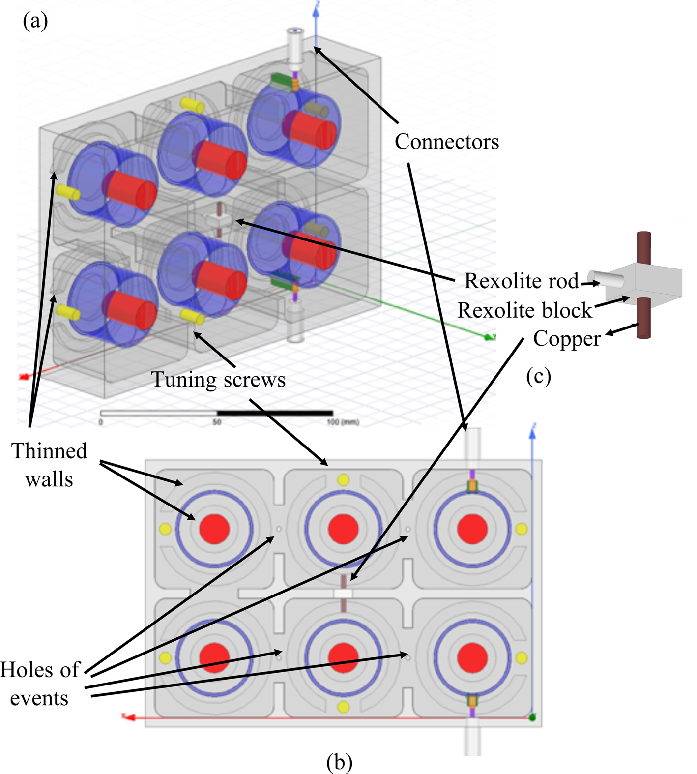
Fig. 6. Sixth-order cross-coupled filter: (a) 3D view, (b) top view, cross-section, and (c) retro-coupling metal rod.

Fig. 7. Ideal (ADS) and electromagnetic (HFSS) simulated responses of the filter: (a) S 21 frequency response and (b) S 11 frequency response.
The layout of the final sixth-order cross-coupled filter is presented in Fig. 6. It consists of:
• six quasi-identical two-sections SIR coaxial resonators whose dimensions are given in Table 2;
• two coaxial connectors (TNC power connectors [24]);
• five irises for the magnetic couplings;
• a retro-coupling metal rod (rexolite support [ɛr = 2.53 − tan(δ) = 0.004] and copper [σ = 58 MS/m]);
• tuning screws to adjust the final response of the whole filter;
• four holes of events of 1 mm radius, which allow air to escape from the filter as it passes from the terrestrial atmosphere to the vacuum of space and for multipactor measurement in the vacuum chamber; and
• thinned walls to increase the irradiated energy required inside the filter for the initiation of secondary electronic emissions during the multipactor test. Thinning was done on the outside of the filter.
The optimization of the whole structure consists of adjusting different geometric parameters to satisfy the requested specifications. In the first-order, the width of the irises and geometric parameters of the isolated coupling metallic rod directly impact the bandwidth and transmission zero level, respectively. For the matching level, the height positioning of the connectors and a slight frequency adjustment of the pairs of resonators is required.
Once the resonator had been correctly defined, the step-by-step procedure required several simulations with HFSS software but converged quite well. Each characteristic of the electrical response, bandwidth (iris sizes), and central frequency (resonators dimensions, Table 2) mainly depends on one geometrical parameter, the influence of the others playing a secondary role. However, to save time or to be more efficient, it is also possible to use dedicated optimization algorithms in such circumstances [Reference Bila, Baillargeat, Aubourg, Verdeyme, Guillon, Seyfert, Grimm, Baratchart, Zanchi and Sombrin25].
Once the electrical response of the filter fulfilled the requested specifications, tuning screws were added. The role of these screws is to correct the eventual technical imperfections of the filter due for example to the tolerance of fabrication. These screws, shown in yellow in Fig. 6, were positioned near the shorted-ends of the C 2 cylinders in order to reduce their impact on the multipactor threshold of the filter. Indeed, in this configuration, the screws are located in a region with a minimum of electric field. We tested several solutions, and the simulations show that the impact of the screws can be very detrimental if they are located, for example, on the opposite side of the filter where they would be close to the open ends of C 2 cylinder.
The electrical responses are shown in Figs 7–10 (dotted lines). They respect the specifications, showing the ability of the topology to resolve this particular filtering problematic. The insertion losses, between 0.2 and 0.45 dB, are better than those imposed by the specifications (<0.5 dB).

Fig. 8. Measurement and electromagnetic simulation of the S 11 frequency responses of the filter.

Fig. 9. Measurement and simulation of the S 21 frequency responses of the filter: (a) insertion losses in the passband, (b) S 21 parameter from 1.4 to 1.7 GHz, and (c) wideband.

Fig. 10. Measurement and electromagnetic simulation of the group delay.
Figure 11 presents the simulation of the multipactor threshold of the filter at the central frequency, f 0 = 1.54 GHz, obtained with Spark3d software. The initial parameters used for this Spark3d simulation were 300 and 700 W for initial and final power, respectively, and the initial number of electrons was fixed at 10 000. The multipactor threshold of the designed filter was 410 W, in accordance with the requested specifications, thus validating the preliminary work presented in the Section “Multipactor threshold evaluation.” The multipactor effect appears between the C 1 and C 2 cylinders. Similar simulations were also performed for certain other frequencies located, for instance, at the maximum group delay, these values are shown in Table 3.

Fig. 11. Multipactor simulation of the L-band filter at 1.54 GHz: (a) SEY curve of silver (ECSS), (b) avalanche of electrons in the filter at 450 W, and (c) simulation results of multipactor threshold.
Table 3. Multipactor threshold for different frequencies in the passband

Fabrication and RF measurements of the L-band filter
Fabrication
For the fabrication, classical mechanical manufacturing processes were used with a precision of ±50 μm.
The fabrication was carried out in three steps:
1. Manufacturing of two aluminum blocks (body and cover) and a copper rod positioned within a rexolite block.
2. A 5-μm thick layer of silver was deposited on the body and cover, to obtain the best electrical conductivity.
3. Brazing of the connectors.
A photograph of the filter after the operation of silvering is shown in Fig. 12. A significant number of screws were added to hermetically close the RF volume.

Fig. 12. Manufactured L-band filter: (a) cover, (b) body, (c) copper rod within rexolite block, and (d) brazing of the connectors.
RF measurements
Figures 8–10 compare the measured and simulated S 11 and S 21 frequency responses, and group delay responses of the filter around the passband and in a wide band. The measured results show a relatively good agreement with the simulated ones, although some differences do appear. We can observe a slight frequency shift in the transmission zero position. We can also notice some differences for the insertion losses and for the matching level. The measured response was obtained by adjusting the tuning screws provided for this purpose, and pre-arranged on the filter body. During the measurements, the screws in the input/output resonators had to be screwed fully home. This is due to several problems that limit the tuning dynamics of these screws. We should point out a difference between the retro-coupling element that was designed and the one that was manufactured: in the latter, the fixation rod was made of copper instead of rexolite. The manufactured retro-coupling element does not match the designed and expected retro-coupling element (Fig. 6). This fabrication difference induced a slight modification of the position of the transmission zeros of the frequency response of the L-band filter. The brazing was also not exactly as requested. Moreover, the roughness of the metallic walls inside the filter impacted the insertion losses.
Multipactor measurements
Test conditions
To measure multipactor effect, it was necessary to control the environment of the thermal vacuum chamber, particularly its cleanliness (atmospheric particles of class 8 according to ISO 14644-1), pressure (<1.5 mPa in the critical areas of the component) and temperature. Figure 13 shows the devices of the test bench, which are as follows. An 90Sr radioactive source is positioned near the critical location of the electronic component. In the design, some parts of the filter walls were manufactured specifically to allow the introduction of primary electrons into the filter. This was practically achieved by making a local circular decrease in the thickness, on one of the walls of the filter, under the six rings between C 2 and C 3. To generate strong RF power, a synthesizer was used delivering a carrier in pulse mode, coupled with traveling-wave tube amplifiers. The multipactor phenomenon could be detected by two systems, based on a phase nulling and on third harmonic principles (Fig. 13) [20].

Fig. 13. Experimental multipactor test set-up overview.
Multipactor measurements
Multipactor measurements were performed for three different frequency points: the center frequency f 0, and the frequencies at the group delay maxima fTPG, for which energy storage was maximal within the filter (Fig. 10). The comparison between the measurements and the simulation performed with Spark3d software is shown in Table 4. The test bench used was limited to a maximum input power Pmax = 450 W. At the center frequency of the filter, neither detection was observed. For the two other frequencies, a multipactor discharge was registered by the phase nulling detection method.
Table 4. Simulated and measured power results

As shown in Table 4, there is a difference of 5 dB between the measured and simulated values. Several hypotheses can explain this difference: a lack of precautions during the machining could have affected the roughness of the filter. A difference between the SEY parameters used during the Spark3d simulation and reality is also possible. We remind that in the Section “Multipactor threshold evaluation,” we pointed out the sensitivity of Spark3d to some SEY parameters. Considering the statistical method used by Spark3d, the final result should be considered as an estimation, particularly if the order (number of half periods) is high (unstable zone), as in the present case. In addition, the detection system (third harmonic principles) is not well suited to high orders [Reference Sorolla26].
Conclusion
In this paper, we show that an SIR coaxial resonator can be a very suitable solution for particular industrial needs. The proposed solution satisfies the electrical specifications of a Tx filter, part of a duplexer, for which the constraints on power handling and size are severe. It should be remembered that the solution based on a uniform coaxial resonator would have been too large and thus detrimental for the future integration of the Rx part of the duplexer.
The simulated and measured frequency responses of the filter are in very good agreement, despite a small number of explainable differences: brazing of the connector, retro-coupling element, and/or roughness of the metallic envelope. These differences are listed in Table 5, in which all the performances are compared with the requested specifications. Finally, the measured multipactor thresholds largely meet the specifications, with a triggering threshold much higher than 400 W. In particular, simulated and experimental results show that, for multipactor threshold, the specifications are reached. However, the underlying reasons for the 5 dB difference between the simulated and experimental data remain to be confirmed. This difference could be exploited to reduce the size of the filter. The next step of this study would be to design the full duplexer, keeping in mind that there is no power handling constraint on the Rx filter.
Table 5. Balance sheet of the results

Acknowledgement
We would like to thank Breizh Usinage Service (Z.A. du Drevers – 29190 Pleyben, France) for manufacturing the filter and Thales Alenia Space (Toulouse, France) for the measurements of the electrical responses and multipactor threshold.
 J. Benedicto obtained a Ph.D. in physics from the University of Blaise Pascal, Clermont-Ferrand, France, in 2013. During her Ph.D., she investigated the potential of metallo-dielectric multilayers, flat lenses with subwavelength resolution, and nonlocality in metals. In 2013, she held a post-doctoral position at the Fresnel Institute, Marseille, France. The fields of application of her postdoctoral research were hybrid magnetic-electric dielectric scatterer near-field and far-field analyses. In 2015, she became an Assistant Professor at Lab-STICC, Brest, France. Her research interests are focused on the modeling and design of passive devices for microwave applications.
 E. Rius is currently a Professor at the University of Brest. From 2016 to 2020, he was Vice Head of Lab-STICC UMR CNRS 6285. His research conducted at Lab-STICC concerns the design of passive microwave devices for centimetric and millimetric wave applications. He is involved in many projects with the two French agencies ANR and CNES, and companies such as Thales Alenia Space. He has supervised over 23 Ph.D. students and several post-docs. He has participated in over 110 Ph.D. and HDR defense juries. In 2013, he was appointed as a European Microwave Lecturer by the European Microwave Association. In 2010, he was the TPC Chair of the 40th edition of the European Microwave Conference (which had over 5000 attendees). He spent several months in Singapore as a Visiting Professor at Nanyang Technological University. He has an h-score of 21, with over 2100 citations overall.
 J.-F. Favennec received a Ph.D. in electronics from the University of Brest, France, in 1990. He received the Accreditation to Supervise Research (HDR) in 2016. He became an Assistant Professor with the École Nationale d'Ingénieurs de Brest, Plouzané, France, in 1991. He mainly teaches electromagnetic theory and microwaves. He currently conducts research at the Laboratoire en Sciences et Techniques de l'Information, de la Communication et de la Connaissance (Lab-STICC), University of Brest. His present research interests include the modeling and design of passive devices for microwave applications, mainly focusing on filters.
 D. Pacaud was born in France, in December 1971. In 2001, he received a Ph.D. degree in Applied Mathematics and Scientific Computing from the University of Bordeaux 1, France. In 1996, he joined the CEG Center (Gramat) to develop powerful electromagnetic numerical techniques. In 2000, he joined IEEA (Paris) to develop RF software. Since 2001, he has been in charge of filters and multiplexer studies and developments for spatial applications at Thales Alenia Space, Toulouse, France. In 2020, he was appointed Thales Microwave Filters Expert. He has authored or co-authored over 40 technical papers in journals or for conferences. He holds 13 technical patents. He acts as reviewer for the European Microwave Conference (EuMC), the French Microwave Days (JNM), the ESA Microwave Technology and Techniques Workshop (MTT), and the ESA/CNES International Workshop on Microwave Filters (IWMF). His main area of interest concerns optimization and computer-aided design (CAD) processes for novel passive microwave products.
 L. Carpentier received his Ph.D. degree in Electrical Engineering from the University of Limoges, France, in 2012. He is currently a Research and Development Engineer in the French Space Agency (CNES) in Toulouse, France, where he is involved in the field of microwave passive components area.
 J. Puech was born in 1974 in Rodez, France. He received an Engineering Diploma degree from the Telecom-SudParis (Institut National des Téléecommunications), Evry, France, in 1998. In January 2000, he joined the Centre National d'Etudes Spatiales, Toulouse, France where he was involved in microwave research activities mainly oriented toward microwave breakdown phenomena (Multipactor effect, Corona effect) within space components and traveling-wave tubes. Since February 2020, he has been working in the field of radiometric remote sensing in the Radar Instrument and Performances department.


 Open access