

1 Introduction
The multiscale feature of turbulent flows has always drawn the attention of scientists since Richardson’s work (Richardson Reference Richardson1922) on the turbulent energy cascade. But, it is only after Kolmogorov’s seminal works on the inertial subrange of turbulence (Kolmogorov Reference Kolmogorov1941a ,Reference Kolmogorov b ) that most research efforts have been devoted to the study of the turbulent multiscale interactions. Kolmogorov’s works contain one of the very few exact and non-trivial results in the field of turbulence. Kolmogorov’s groundbreaking intuition was to reduce the complex problem of turbulence to its essential features, by assuming homogeneity and isotropy. In these conditions, the main process governing turbulence is the energy cascade among scales which is described by a single scalar parameter, the averaged dissipation rate. Much of the current understanding of fully developed turbulence is based on this result and relies on a general equation which is known as the Kolmogorov equation,
 $$\begin{eqnarray}\langle {\it\delta}u_{\Vert }^{3}\rangle -6{\it\nu}\frac{\text{d}}{\text{d}r}\langle {\it\delta}u_{\Vert }^{2}\rangle =-\frac{4}{5}\langle {\it\epsilon}\rangle r,\end{eqnarray}$$
where
 ${\it\delta}u_{\Vert }$
is the longitudinal velocity increment between two points with separation
${\it\delta}u_{\Vert }$
is the longitudinal velocity increment between two points with separation
 $r$
,
$r$
,
 ${\it\epsilon}$
is the rate of dissipation,
${\it\epsilon}$
is the rate of dissipation,
 ${\it\nu}$
is the kinematic viscosity and angular brackets denote ensemble average. The basic result of (1.1) is that, at sufficiently large Reynolds numbers, an intermediate range of scales exists, away from energy injection and energy dissipation, where the energy flux across scales is identified as
${\it\nu}$
is the kinematic viscosity and angular brackets denote ensemble average. The basic result of (1.1) is that, at sufficiently large Reynolds numbers, an intermediate range of scales exists, away from energy injection and energy dissipation, where the energy flux across scales is identified as
 $\langle {\it\delta}u_{\Vert }^{3}\rangle /r$
. This expression provides a direct evaluation of the energy cascade through the inertial range (see Nie & Tanveer Reference Nie and Tanveer1999; Aoyama et al.
Reference Aoyama, Ishihara, Kaneda, Yokokawa, Itakura and Uno2005; Gotoh & Watanabe Reference Gotoh and Watanabe2005; Ishihara, Gotoh & Kaneda Reference Ishihara, Gotoh and Kaneda2009).
$\langle {\it\delta}u_{\Vert }^{3}\rangle /r$
. This expression provides a direct evaluation of the energy cascade through the inertial range (see Nie & Tanveer Reference Nie and Tanveer1999; Aoyama et al.
Reference Aoyama, Ishihara, Kaneda, Yokokawa, Itakura and Uno2005; Gotoh & Watanabe Reference Gotoh and Watanabe2005; Ishihara, Gotoh & Kaneda Reference Ishihara, Gotoh and Kaneda2009).
Actually, real turbulent flows have a much richer physics, involving, beside energy transfer, anisotropic production and inhomogeneous spatial fluxes. Such processes are strongly scale and position dependent and lead to a geometrically complex redistribution of energy. Several attempts aiming at the ultimate understanding of the energy path from production to dissipation in wall-bounded flows can be found in the recent literature. The nonlinear transfer of the turbulent kinetic energy has been investigated by Domaradzki et al. (Reference Domaradzki, Liu, Härtel and Kleiser1994) in two different wall-bounded flows, with and without a mean flow, by means of a mixed physical–spectral decomposition of the nonlinear term of the Navier–Stokes equations. The analysis of the energy redistribution among different distances from the wall and among lateral wavenumbers highlights that energy is transferred most effectively between scales of similar size and suggests the possible presence of a reverse cascade from large to small wavenumbers in the near-wall region. Similar conclusions have been drawn by Dunn & Morrison (Reference Dunn and Morrison2003) where a wavelet decomposition is used to provide a dual scale/physical space description of the production and flux of energy. The analysis reveals that the transfer is predominantly local. There are however complications arising from the fact that both forward and backward energy transfer are present. A generalized form of the Kolmogorov’s equation is proposed by Danaila et al. (Reference Danaila, Anselmet, Zhou and Antonia2001) showing how the inhomogeneity of the large scales quantitatively acts along the direction normal to the wall. The energy transfer has been studied also from a phenomenological point of view in terms of size of turbulent structures. In fact, since the turbulent structures near the wall are small while those further away from the wall are large, the spatial flux of energy from the near-wall region to the bulk flow is conjectured to be an example of inverse cascade (Jiménez Reference Jiménez1999). Following this line of reasoning, in Adrian, Meinhart & Tomkins (Reference Adrian, Meinhart and Tomkins2000), forward and reverse cascade are proposed to coexist through a phenomenological model of hairpin packets within the logarithmic layer of wall turbulence while, in Lozano-Durán & Jiménez (Reference Lozano-Durán and Jiménez2014), statistics of vortex cluster and Reynolds stress structures are used to identify cascades. A recent review of the variety of approaches used for the study of the turbulent cascades can be found in Jiménez (Reference Jiménez2012).
All of these approaches, however, do not fully account for the multidimensional nature and the directionality of the process. To provide a more complete view, the four-fifths law in the form of a balance equation for second-order structure function, originally proposed by Hill (Reference Hill2002), was used by Marati, Casciola & Piva (Reference Marati, Casciola and Piva2004) to address the energy transfer in both spatial and scale spaces for a turbulent channel flow. The multidimensional and directional description provided by this equation was exploited by Cimarelli, De Angelis & Casciola (Reference Cimarelli, De Angelis and Casciola2013) to understand the formation and sustainment of long and wide turbulent fluctuations. In that paper, a model for the energy cascade was also developed to account for the dual nature of the energy transfer consisting of forward and reverse cascades ascending from the wall. From the model a large eddy simulation (LES) closure was developed, Cimarelli & De Angelis (Reference Cimarelli and De Angelis2011, Reference Cimarelli and De Angelis2012, Reference Cimarelli and De Angelis2014), that was shown able to account for the small scale behaviour responsible for the backward energy transfer.
Aim of the present work is to extend the analysis of the generalized Kolmogorov equation to directly address the flux of energy between different wall-normal scales at different distances from the wall. The topic has long been central in turbulence research. Probably one of the first instances is the study of the spectral budget of turbulent kinetic energy reported by Lumley (Reference Lumley1964). He argued that the spatial inhomogeneity of wall turbulence leads to a complex energy flux where an inverse energy transfer occurs. A phenomenological theory was proposed by Townsend (Reference Townsend1976) based on his famous attached eddy hypothesis. The description consists of elongated turbulent structures attached to the wall which are generated by the lift up and by the orienting effect of the mean flow on the spanwise vorticity (see, e.g., Perry, Henbest & Chong Reference Perry, Henbest and Chong1986; Marusic Reference Marusic2001; Nickels et al. Reference Nickels, Marusic, Hafez, Hutchins and Chong2007). These turbulent structures while moving away from the wall, grow and remain attached to the wall thus leading to an increase of wall-normal scales corresponding to a sort of reverse cascade (see Piomelli, Yu & Adrian Reference Piomelli, Yu and Adrian1996). At a certain point, these structures detach and break down into smaller structures giving rise to a form of forward cascade.
At present, much is understood about the nature of turbulence in canonical wall-bounded flows. However, the comprehensive description simultaneously encompassing spatial and scale-space features provided by the generalized Kolmogorov equation has been only incompletely exploited. The appeal of this approach is its ability to provide a clear picture of the basic cascade process, as described in the work of Kolmogorov, combined with the possibility to rigorously tackle inhomogeneity and anisotropy. The central quantity in the theory is the second-order structure function. The conservative equation for this observable precisely identifies the relevant fluxes in the spatial and scale space and allows for a rigorous definition of the corresponding production and dissipation. Structure functions have long been exploited for basic studies in turbulence. In homogeneous conditions, the second-order structure function can be taken to represent the energy content of the small scales. In this context the second-order structure function can be referred to as the scale energy. When extending its usage to strongly inhomogeneous flows this interpretation becomes somewhat arguable especially for large separations. Nevertheless, the elegant formulation endows such structure function with its physical interpretation, see Davidson (Reference Davidson2004, pp. 88–94). Indeed, the Kolmogorov equation is an exact balance between second- and third-order moments (Monin & Yaglom Reference Monin and Yaglom1975; Danaila et al.
Reference Danaila, Anselmet, Zhou and Antonia2001; Danaila, Anselmet & Zhou Reference Danaila, Anselmet and Zhou2004; Germano Reference Germano2007; Gomes-Fernandes, Ganapathisubramani & Vassilicos Reference Gomes-Fernandes, Ganapathisubramani and Vassilicos2015) showing that the rate of energy dissipation
 $\langle {\it\epsilon}\rangle$
is associated, at any scale, with fluxes which in turn are fed by local sources. Following the different ranges of scales and positions encountered by the fluxes, the second- and third-order moments eventually assume their physical interpretation of scale energy and scale-energy flux.
$\langle {\it\epsilon}\rangle$
is associated, at any scale, with fluxes which in turn are fed by local sources. Following the different ranges of scales and positions encountered by the fluxes, the second- and third-order moments eventually assume their physical interpretation of scale energy and scale-energy flux.
The work is organized as follows. In § 2 we introduce the generalized Kolmogorov equation and the multidimensional space of scales/positions analysed here. In § 3 we start describing the statistics by showing the topology of scale energy and of scale-energy source while the structure of the scale-energy fluxes is depicted in § 4. Finally § 5 reports a discussion on the combined role of scale-energy flux and scale-energy source while § 6 closes the paper with final remarks.
2 The generalized Kolmogorov equation and the
 $(r_{y},r_{z},Y_{c})$
space
$(r_{y},r_{z},Y_{c})$
space

The second-order structure function
 $\langle {\it\delta}u^{2}\rangle$
, where
$\langle {\it\delta}u^{2}\rangle$
, where
 ${\it\delta}u^{2}={\it\delta}u_{i}{\it\delta}u_{i}$
, involves the fluctuation velocity difference
${\it\delta}u^{2}={\it\delta}u_{i}{\it\delta}u_{i}$
, involves the fluctuation velocity difference
 ${\it\delta}u_{i}=u_{i}(x_{s}^{\prime \prime })-u_{i}(x_{s}^{\prime })$
at two points,
${\it\delta}u_{i}=u_{i}(x_{s}^{\prime \prime })-u_{i}(x_{s}^{\prime })$
at two points,
 $x_{s}^{\prime \prime }$
and
$x_{s}^{\prime \prime }$
and
 $x_{s}^{\prime }$
, where the mid-point and the separation are
$x_{s}^{\prime }$
, where the mid-point and the separation are
 $X_{s}=\left(x_{s}^{\prime \prime }+x_{s}^{\prime }\right)/2$
and
$X_{s}=\left(x_{s}^{\prime \prime }+x_{s}^{\prime }\right)/2$
and
 $r_{s}=x_{s}^{\prime \prime }-x_{s}^{\prime }$
. The balance equation for second-order structure function allows us to study the global statistical properties of turbulence as a function of the separation vector between the two points,
$r_{s}=x_{s}^{\prime \prime }-x_{s}^{\prime }$
. The balance equation for second-order structure function allows us to study the global statistical properties of turbulence as a function of the separation vector between the two points,
 $r_{s}$
, and of the spatial position of the mid-point
$r_{s}$
, and of the spatial position of the mid-point
 $X_{s}$
, hence describing the scale-dependent mechanisms in the presence of inhomogeneity. Hereafter, as anticipated in the introduction, we will often refer to the second-order structure function as the scale energy. The balance equation of
$X_{s}$
, hence describing the scale-dependent mechanisms in the presence of inhomogeneity. Hereafter, as anticipated in the introduction, we will often refer to the second-order structure function as the scale energy. The balance equation of
 $\langle {\it\delta}u^{2}\rangle$
in wall flows is the generalized Kolmogorov equation (Hill Reference Hill2002) which for a turbulent channel flow with longitudinal mean velocity
$\langle {\it\delta}u^{2}\rangle$
in wall flows is the generalized Kolmogorov equation (Hill Reference Hill2002) which for a turbulent channel flow with longitudinal mean velocity
 $U(y)$
(Marati et al.
Reference Marati, Casciola and Piva2004) reads
$U(y)$
(Marati et al.
Reference Marati, Casciola and Piva2004) reads
 $$\begin{eqnarray}\displaystyle & & \displaystyle \frac{\partial \langle {\it\delta}u^{2}{\it\delta}u_{i}\rangle }{\partial r_{i}}+\frac{\partial \langle {\it\delta}u^{2}{\it\delta}U\rangle }{\partial r_{x}}+2\langle {\it\delta}u{\it\delta}v\rangle \left(\frac{\text{d}U}{\text{d}y}\right)^{\ast }+2\langle {\it\delta}uv^{\ast }\rangle {\it\delta}\left(\frac{\text{d}U}{\text{d}y}\right)+\frac{\partial \langle v^{\ast }{\it\delta}u^{2}\rangle }{\partial Y_{c}}\nonumber\\ \displaystyle & & \displaystyle \quad =-4\langle {\it\epsilon}^{\ast }\rangle +2{\it\nu}\frac{\partial ^{2}\langle {\it\delta}u^{2}\rangle }{\partial r_{i}\partial r_{i}}-\frac{2}{{\it\rho}}\frac{\partial \langle {\it\delta}p{\it\delta}v\rangle }{\partial Y_{c}}+\frac{{\it\nu}}{2}\frac{\partial ^{2}\langle {\it\delta}u^{2}\rangle }{\partial {Y_{c}}^{2}},\end{eqnarray}$$
where the asterisk denotes the arithmetic average of a variable at the points
 $X_{s}\pm r_{s}/2$
,
$X_{s}\pm r_{s}/2$
,
 $Y_{c}=X_{2}$
is the wall-normal coordinate of the mid-point,
$Y_{c}=X_{2}$
is the wall-normal coordinate of the mid-point,
 $v=u_{2}$
is the wall-normal velocity,
$v=u_{2}$
is the wall-normal velocity,
 ${\it\nu}$
is kinematic viscosity,
${\it\nu}$
is kinematic viscosity,
 ${\it\rho}$
is the density and
${\it\rho}$
is the density and
 ${\it\epsilon}={\it\nu}(\partial u_{i}/\partial x_{j})(\partial u_{i}/\partial x_{j})$
is the pseudo-dissipation. For the symmetries of the channel, the angular brackets operator
${\it\epsilon}={\it\nu}(\partial u_{i}/\partial x_{j})(\partial u_{i}/\partial x_{j})$
is the pseudo-dissipation. For the symmetries of the channel, the angular brackets operator
 $\langle \cdot \rangle$
denotes spatial average along the wall-parallel homogeneous directions and average over different uncorrelated fields. It is useful to recast (2.1) in terms of a four-dimensional vector field,
$\langle \cdot \rangle$
denotes spatial average along the wall-parallel homogeneous directions and average over different uncorrelated fields. It is useful to recast (2.1) in terms of a four-dimensional vector field,
 $\unicode[STIX]{x1D731}=({\it\Phi}_{r_{x}},{\it\Phi}_{r_{y}},{\it\Phi}_{r_{z}},{\it\Phi}_{c})$
, hereafter called the scale-energy hyper-flux, defined in a four-dimensional space
$\unicode[STIX]{x1D731}=({\it\Phi}_{r_{x}},{\it\Phi}_{r_{y}},{\it\Phi}_{r_{z}},{\it\Phi}_{c})$
, hereafter called the scale-energy hyper-flux, defined in a four-dimensional space
 $(r_{x},r_{y},r_{z},Y_{c})$
,
$(r_{x},r_{y},r_{z},Y_{c})$
,
 $$\begin{eqnarray}\boldsymbol{{\rm\nabla}}_{4}\boldsymbol{\cdot }\unicode[STIX]{x1D731}(\boldsymbol{r},Y_{c})={\it\xi}(\boldsymbol{r},Y_{c}),\end{eqnarray}$$
where
 $\boldsymbol{{\rm\nabla}}_{4}$
is the four-dimensional gradient and
$\boldsymbol{{\rm\nabla}}_{4}$
is the four-dimensional gradient and
 ${\it\xi}=-2\langle {\it\delta}u{\it\delta}v\rangle (\text{d}U/\text{d}y)^{\ast }-2\langle {\it\delta}uv^{\ast }\rangle {\it\delta}(\text{d}U/\text{d}y)-4\langle {\it\epsilon}^{\ast }\rangle$
is the scale-energy source/sink. The flux in the three-dimensional space of scales is
${\it\xi}=-2\langle {\it\delta}u{\it\delta}v\rangle (\text{d}U/\text{d}y)^{\ast }-2\langle {\it\delta}uv^{\ast }\rangle {\it\delta}(\text{d}U/\text{d}y)-4\langle {\it\epsilon}^{\ast }\rangle$
is the scale-energy source/sink. The flux in the three-dimensional space of scales is
 $\unicode[STIX]{x1D731}_{r}=({\it\Phi}_{r_{x}},{\it\Phi}_{r_{y}},{\it\Phi}_{r_{z}})=\langle {\it\delta}u^{2}{\it\delta}\boldsymbol{u}\rangle +\langle {\it\delta}u^{2}{\it\delta}U\rangle \hat{\boldsymbol{e}}_{x}-2{\it\nu}\boldsymbol{{\rm\nabla}}_{r}\langle {\it\delta}u^{2}\rangle$
, where
$\unicode[STIX]{x1D731}_{r}=({\it\Phi}_{r_{x}},{\it\Phi}_{r_{y}},{\it\Phi}_{r_{z}})=\langle {\it\delta}u^{2}{\it\delta}\boldsymbol{u}\rangle +\langle {\it\delta}u^{2}{\it\delta}U\rangle \hat{\boldsymbol{e}}_{x}-2{\it\nu}\boldsymbol{{\rm\nabla}}_{r}\langle {\it\delta}u^{2}\rangle$
, where
 $\hat{\boldsymbol{e}}_{x}$
is the unit vector in the mean flow direction
$\hat{\boldsymbol{e}}_{x}$
is the unit vector in the mean flow direction
 $x$
. In addition to the flux in the space of scales, the generalized Kolmogorov equation features the spatial flux
$x$
. In addition to the flux in the space of scales, the generalized Kolmogorov equation features the spatial flux
 ${\it\Phi}_{c}=\langle v^{\ast }{\it\delta}u^{2}\rangle +2\langle {\it\delta}p{\it\delta}v\rangle /{\it\rho}-({\it\nu}/2)\partial \langle {\it\delta}u^{2}\rangle /\partial Y_{c}$
.
${\it\Phi}_{c}=\langle v^{\ast }{\it\delta}u^{2}\rangle +2\langle {\it\delta}p{\it\delta}v\rangle /{\it\rho}-({\it\nu}/2)\partial \langle {\it\delta}u^{2}\rangle /\partial Y_{c}$
.
Equation (2.2) has been analysed in the hyper-plane
 $r_{y}=0$
in Cimarelli et al. (Reference Cimarelli, De Angelis and Casciola2013). This approach allowed us to identify the reverse energy transfer as a crucial mechanism characterizing wall turbulence, responsible for the formation of the commonly observed very long and wide velocity fluctuations in the outer region of the flow. Here, the analysis will be performed in the hyper-plane
$r_{y}=0$
in Cimarelli et al. (Reference Cimarelli, De Angelis and Casciola2013). This approach allowed us to identify the reverse energy transfer as a crucial mechanism characterizing wall turbulence, responsible for the formation of the commonly observed very long and wide velocity fluctuations in the outer region of the flow. Here, the analysis will be performed in the hyper-plane
 $r_{x}=0$
, i.e. in the
$r_{x}=0$
, i.e. in the
 $(r_{y},r_{z},Y_{c})$
-space. The present results will allow us for the first time to distinguish in a well-defined mathematical framework the flux in the space of wall-normal scales
$(r_{y},r_{z},Y_{c})$
-space. The present results will allow us for the first time to distinguish in a well-defined mathematical framework the flux in the space of wall-normal scales
 $r_{y}$
from the spatial flux among different wall distances
$r_{y}$
from the spatial flux among different wall distances
 $Y_{c}$
. Indeed, due to violation of spatial homogeneity, this distinction lacks of a classical spectral description.
$Y_{c}$
. Indeed, due to violation of spatial homogeneity, this distinction lacks of a classical spectral description.
Given the definition of velocity increments, the
 $r_{y}$
direction is limited by the presence of the wall. In particular, for a given wall distance
$r_{y}$
direction is limited by the presence of the wall. In particular, for a given wall distance
 $Y_{c}$
, the space of wall-normal scales extends from zero to twice the distance from the wall,
$Y_{c}$
, the space of wall-normal scales extends from zero to twice the distance from the wall,
 $r_{y}\in [0,2Y_{c}]$
. Actually, negative increments, i.e.
$r_{y}\in [0,2Y_{c}]$
. Actually, negative increments, i.e.
 $r_{y}\in [-2Y_{c},2Y_{c}]$
, are not considered here since the symmetry of the flow is such that the transformation
$r_{y}\in [-2Y_{c},2Y_{c}]$
, are not considered here since the symmetry of the flow is such that the transformation
 $\boldsymbol{r}\rightarrow -\boldsymbol{r}$
,
$\boldsymbol{r}\rightarrow -\boldsymbol{r}$
,
 $\widetilde{Y}_{c}=\text{const.}$
leads to
$\widetilde{Y}_{c}=\text{const.}$
leads to
 $\unicode[STIX]{x1D731}_{r}\rightarrow -\unicode[STIX]{x1D731}_{r}$
and
$\unicode[STIX]{x1D731}_{r}\rightarrow -\unicode[STIX]{x1D731}_{r}$
and
 ${\it\Phi}_{c}\rightarrow {\it\Phi}_{c}$
. This transformation leaves quantities such as
${\it\Phi}_{c}\rightarrow {\it\Phi}_{c}$
. This transformation leaves quantities such as
 ${\it\delta}u^{2}$
and
${\it\delta}u^{2}$
and
 $v^{\ast }$
statistically invariant while reversing the sign of vectors such as
$v^{\ast }$
statistically invariant while reversing the sign of vectors such as
 ${\it\delta}u_{i}$
and
${\it\delta}u_{i}$
and
 $\boldsymbol{{\rm\nabla}}_{r}$
. It is worth pointing out that the space of wall-normal scales,
$\boldsymbol{{\rm\nabla}}_{r}$
. It is worth pointing out that the space of wall-normal scales,
 $r_{y}$
, involves velocity increments between two points separated in the inhomogeneous direction. By definition, the second-order structure function can be written as
$r_{y}$
, involves velocity increments between two points separated in the inhomogeneous direction. By definition, the second-order structure function can be written as
 $\langle {\it\delta}u^{2}\rangle =2\langle k\rangle (Y_{c}+r_{y}/2)+2\langle k\rangle (Y_{c}-r_{y}/2)-2\langle u_{i}(Y_{c}+r_{y}/2)u_{i}(Y_{c}-r_{y}/2)\rangle$
where
$\langle {\it\delta}u^{2}\rangle =2\langle k\rangle (Y_{c}+r_{y}/2)+2\langle k\rangle (Y_{c}-r_{y}/2)-2\langle u_{i}(Y_{c}+r_{y}/2)u_{i}(Y_{c}-r_{y}/2)\rangle$
where
 $k=u_{i}u_{i}/2$
and increments are considered only in the wall-normal direction for simplicity. This expression allows us to highlight how spatial inhomogeneity enters the space of wall-normal scales
$k=u_{i}u_{i}/2$
and increments are considered only in the wall-normal direction for simplicity. This expression allows us to highlight how spatial inhomogeneity enters the space of wall-normal scales
 $r_{y}$
. In particular, the inhomogeneous spatial distribution of energy
$r_{y}$
. In particular, the inhomogeneous spatial distribution of energy
 $\langle k\rangle (y)$
contributes to the value of scale energy by means of a scale-dependent quantity
$\langle k\rangle (y)$
contributes to the value of scale energy by means of a scale-dependent quantity
 $4\langle k\rangle ^{\ast }(Y_{c},r_{y})=2\langle k\rangle (Y_{c}+r_{y}/2)+2\langle k\rangle (Y_{c}-r_{y}/2)$
. For small wall-normal scales compared with the length of inhomogeneity of the flow, the dependence of
$4\langle k\rangle ^{\ast }(Y_{c},r_{y})=2\langle k\rangle (Y_{c}+r_{y}/2)+2\langle k\rangle (Y_{c}-r_{y}/2)$
. For small wall-normal scales compared with the length of inhomogeneity of the flow, the dependence of
 $4\langle k\rangle ^{\ast }$
on
$4\langle k\rangle ^{\ast }$
on
 $r_{y}$
is small and, hence, scale energy is roughly unaffected by inhomogeneity. In contrast, for large wall-normal scales, the inhomogeneous spatial distribution of energy
$r_{y}$
is small and, hence, scale energy is roughly unaffected by inhomogeneity. In contrast, for large wall-normal scales, the inhomogeneous spatial distribution of energy
 $k(y)$
significantly contribute to the value of scale energy.
$k(y)$
significantly contribute to the value of scale energy.
The data used for the present analysis come from a channel-flow direct numerical simulation (DNS) at
 $Re_{{\it\tau}}=u_{{\it\tau}}h/{\it\nu}=2003$
, where
$Re_{{\it\tau}}=u_{{\it\tau}}h/{\it\nu}=2003$
, where
 $h$
is the channel half-height. Throughout the paper, inner variables will be used and denoted with the superscript +, implying normalization of lengths with the friction length
$h$
is the channel half-height. Throughout the paper, inner variables will be used and denoted with the superscript +, implying normalization of lengths with the friction length
 ${\it\nu}/u_{{\it\tau}}$
and velocities with the friction velocity
${\it\nu}/u_{{\it\tau}}$
and velocities with the friction velocity
 $u_{{\it\tau}}=\sqrt{{\it\tau}_{w}/{\it\rho}}$
where
$u_{{\it\tau}}=\sqrt{{\it\tau}_{w}/{\it\rho}}$
where
 ${\it\tau}_{w}$
is the average shear stress at the wall. The computational domain is
${\it\tau}_{w}$
is the average shear stress at the wall. The computational domain is
 $8{\rm\pi}h\times 2h\times 3{\rm\pi}h$
and the resolution in the homogeneous directions is
$8{\rm\pi}h\times 2h\times 3{\rm\pi}h$
and the resolution in the homogeneous directions is
 ${\rm\Delta}x^{+}=8.2$
and
${\rm\Delta}x^{+}=8.2$
and
 ${\rm\Delta}z^{+}=4.1$
, see Hoyas & Jiménez (Reference Hoyas and Jiménez2006) for the details of the simulation. The velocity and pressure increments,
${\rm\Delta}z^{+}=4.1$
, see Hoyas & Jiménez (Reference Hoyas and Jiménez2006) for the details of the simulation. The velocity and pressure increments,
 ${\it\delta}u_{i}$
and
${\it\delta}u_{i}$
and
 ${\it\delta}p$
respectively, appearing in the generalized Kolmogorov equation (2.1) are computed directly in physical space over the whole computational box by considering the values of velocity and pressure at the two points of the increment. Then, the terms of the generalized Kolmogorov equation (2.1) are computed and averaged by considering spatial homogeneity in the streamwise and spanwise directions and using 15 independent fields. The statistical convergence of the data is measured by considering the accuracy with which (2.1) is satisfied. The mean unbalance of the terms of (2.1) is found to be less than 1.5 % of the local dissipation.
${\it\delta}p$
respectively, appearing in the generalized Kolmogorov equation (2.1) are computed directly in physical space over the whole computational box by considering the values of velocity and pressure at the two points of the increment. Then, the terms of the generalized Kolmogorov equation (2.1) are computed and averaged by considering spatial homogeneity in the streamwise and spanwise directions and using 15 independent fields. The statistical convergence of the data is measured by considering the accuracy with which (2.1) is satisfied. The mean unbalance of the terms of (2.1) is found to be less than 1.5 % of the local dissipation.

Figure 1. Behaviour of scale energy
 $\langle {\it\delta}u^{2}\rangle$
in the
$\langle {\it\delta}u^{2}\rangle$
in the
 $(r_{y},r_{z},Y_{c})$
space. (a) Scale energy is shown with contours in the
$(r_{y},r_{z},Y_{c})$
space. (a) Scale energy is shown with contours in the
 $r_{z}=0$
,
$r_{z}=0$
,
 $r_{y}=0$
and
$r_{y}=0$
and
 $r_{y}^{+}=2Y_{c}^{+}-30$
planes. (b,c) The front and lateral view of the contours of
$r_{y}^{+}=2Y_{c}^{+}-30$
planes. (b,c) The front and lateral view of the contours of
 $\langle {\it\delta}u^{2}\rangle$
in the planes
$\langle {\it\delta}u^{2}\rangle$
in the planes
 $r_{y}^{+}=0$
and
$r_{y}^{+}=0$
and
 $r_{z}^{+}=1000$
, respectively.
$r_{z}^{+}=1000$
, respectively.

Figure 2. Behaviour of scale energy in the
 $r_{y}=0$
plane. (a) Plot of
$r_{y}=0$
plane. (a) Plot of
 $\langle {\it\delta}u^{2}\rangle$
as a function of
$\langle {\it\delta}u^{2}\rangle$
as a function of
 $r_{z}$
for different wall distances from its maximum at
$r_{z}$
for different wall distances from its maximum at
 $Y_{c}^{+}=18$
to
$Y_{c}^{+}=18$
to
 $Y_{c}^{+}=900$
. The arrow indicates increasing wall distances. (b) Plot of
$Y_{c}^{+}=900$
. The arrow indicates increasing wall distances. (b) Plot of
 $\langle {\it\delta}u^{2}\rangle$
as a function of
$\langle {\it\delta}u^{2}\rangle$
as a function of
 $Y_{c}$
for different
$Y_{c}$
for different
 $r_{z}$
. The arrow indicates increasing spanwise separations. The inset plot is an enlargement of the near-wall behaviour.
$r_{z}$
. The arrow indicates increasing spanwise separations. The inset plot is an enlargement of the near-wall behaviour.
3 Scale energy and scale-energy source
We start by analysing the second-order structure function in the multidimensional
 $(r_{y},r_{z},Y_{c})$
space, i.e.
$(r_{y},r_{z},Y_{c})$
space, i.e.
 $r_{x}^{+}=0$
, see figure 1(a) for a global view. The plot shows isolines of scale energy on two coordinate planes, namely
$r_{x}^{+}=0$
, see figure 1(a) for a global view. The plot shows isolines of scale energy on two coordinate planes, namely
 $r_{z}^{+}=0$
and
$r_{z}^{+}=0$
and
 $r_{y}^{+}=0$
, and a third oblique plane slightly displaced (30 wall units) from
$r_{y}^{+}=0$
, and a third oblique plane slightly displaced (30 wall units) from
 $r_{y}^{+}=2Y_{c}^{+}$
(recall that the solid wall limits the maximum allowed wall-normal separation to twice the wall-normal distance of the mid-point,
$r_{y}^{+}=2Y_{c}^{+}$
(recall that the solid wall limits the maximum allowed wall-normal separation to twice the wall-normal distance of the mid-point,
 $0\leqslant r_{y}^{+}\leqslant 2Y_{c}^{+}$
). In figure 1(c) the isolines are plotted on the planes
$0\leqslant r_{y}^{+}\leqslant 2Y_{c}^{+}$
). In figure 1(c) the isolines are plotted on the planes
 $r_{z}^{+}=1000$
. The relative maxima of the second-order structure function apparent in this plot are roughly located at
$r_{z}^{+}=1000$
. The relative maxima of the second-order structure function apparent in this plot are roughly located at
 $r_{y}^{+}=2Y_{c}^{+}-30$
, i.e. the oblique plane in figure 1(a) contains these local maxima. In figure 1(b) scale energy is shown in the plane
$r_{y}^{+}=2Y_{c}^{+}-30$
, i.e. the oblique plane in figure 1(a) contains these local maxima. In figure 1(b) scale energy is shown in the plane
 $r_{y}^{+}=0$
, see also figure 2 where a detailed view of
$r_{y}^{+}=0$
, see also figure 2 where a detailed view of
 $\langle {\it\delta}u^{2}\rangle$
in the
$\langle {\it\delta}u^{2}\rangle$
in the
 $r_{y}=0$
plane is shown as a function of the spanwise separation for different
$r_{y}=0$
plane is shown as a function of the spanwise separation for different
 $Y_{c}$
in figure 2(a) and as a function of the wall distance for different
$Y_{c}$
in figure 2(a) and as a function of the wall distance for different
 $r_{z}$
in figure 2(b). The behaviour of scale energy as a function of
$r_{z}$
in figure 2(b). The behaviour of scale energy as a function of
 $Y_{c}^{+}$
is not monotonous, with maxima occurring in the near-wall region, see figures 1(b) and 2(b). Observe that the
$Y_{c}^{+}$
is not monotonous, with maxima occurring in the near-wall region, see figures 1(b) and 2(b). Observe that the
 $Y_{c}^{+}$
location of the maxima becomes independent of
$Y_{c}^{+}$
location of the maxima becomes independent of
 $r_{z}^{+}$
for large values of the latter and takes place at
$r_{z}^{+}$
for large values of the latter and takes place at
 $Y_{c}^{+}=18$
, see the inset plot of figure 2(b). The behaviour of scale energy in the spanwise scales is again not monotonous with maxima occurring for relatively large spanwise scales, see figures 1(b) and 2(a). The scales where such maxima occur increase with the distance from the wall. These maxima correspond to negative minima in the correlation,
$Y_{c}^{+}=18$
, see the inset plot of figure 2(b). The behaviour of scale energy in the spanwise scales is again not monotonous with maxima occurring for relatively large spanwise scales, see figures 1(b) and 2(a). The scales where such maxima occur increase with the distance from the wall. These maxima correspond to negative minima in the correlation,
 $\langle \boldsymbol{u}(X_{c}^{+},Y_{c}^{+},Z_{c}^{+}+r_{z}^{+}/2)\boldsymbol{\cdot }\boldsymbol{u}(X_{c}^{+},Y_{c}^{+},Z_{c}^{+}-r_{z}^{+}/2)\rangle =\langle k(Y_{c}^{+})\rangle -\langle {\it\delta}u^{2}(Y_{c}^{+},r_{z}^{+})\rangle /2$
. At careful inspection, the absolute maximum of the structure function emerges at scales order
$\langle \boldsymbol{u}(X_{c}^{+},Y_{c}^{+},Z_{c}^{+}+r_{z}^{+}/2)\boldsymbol{\cdot }\boldsymbol{u}(X_{c}^{+},Y_{c}^{+},Z_{c}^{+}-r_{z}^{+}/2)\rangle =\langle k(Y_{c}^{+})\rangle -\langle {\it\delta}u^{2}(Y_{c}^{+},r_{z}^{+})\rangle /2$
. At careful inspection, the absolute maximum of the structure function emerges at scales order
 $r_{z}^{+}\simeq 1000$
and for
$r_{z}^{+}\simeq 1000$
and for
 $Y_{c}^{+}=18$
. This value could be related to the presence of large coherent structures in the channel flow, see e.g. Monty et al. (Reference Monty, Stewart, Williams and Chong2007). The behaviour at small separations is consistent with that already described in a previous paper (Saikrishnan et al.
Reference Saikrishnan, De Angelis, Longmire, Marusic, Casciola and Piva2012) at Reynolds number order 500 and 1000. In particular, in figure 2(a), a local maximum is observed at small scales
$Y_{c}^{+}=18$
. This value could be related to the presence of large coherent structures in the channel flow, see e.g. Monty et al. (Reference Monty, Stewart, Williams and Chong2007). The behaviour at small separations is consistent with that already described in a previous paper (Saikrishnan et al.
Reference Saikrishnan, De Angelis, Longmire, Marusic, Casciola and Piva2012) at Reynolds number order 500 and 1000. In particular, in figure 2(a), a local maximum is observed at small scales
 $r_{z}^{+}\simeq 80$
within the buffer layer. It is worth recalling that, at large separations (increasing
$r_{z}^{+}\simeq 80$
within the buffer layer. It is worth recalling that, at large separations (increasing
 $r_{z}^{+}$
), when the turbulent signal becomes uncorrelated, the second-order structure function approaches twice the local value of the turbulent kinetic energy,
$r_{z}^{+}$
), when the turbulent signal becomes uncorrelated, the second-order structure function approaches twice the local value of the turbulent kinetic energy,
 $\lim _{r_{z}^{+}\rightarrow \infty }\langle {\it\delta}u^{2}(Y_{c}^{+},r_{y}^{+}=0,r_{z}^{+})\rangle =2\langle k(Y_{c}^{+})\rangle$
. Overall, for sufficiently large
$\lim _{r_{z}^{+}\rightarrow \infty }\langle {\it\delta}u^{2}(Y_{c}^{+},r_{y}^{+}=0,r_{z}^{+})\rangle =2\langle k(Y_{c}^{+})\rangle$
. Overall, for sufficiently large
 $r_{z}^{+}$
, increasing the distance from the wall, the scale energy tends to decrease, following the trend of the turbulent kinetic energy. Increasing
$r_{z}^{+}$
, increasing the distance from the wall, the scale energy tends to decrease, following the trend of the turbulent kinetic energy. Increasing
 $r_{z}^{+}$
a change in the concavity of the plots occurs that ultimately recovers the anomalous behaviour of the turbulent kinetic energy profile which at larger Reynolds number should indicate the presence of a second peak in the overlap layer (Hutchins & Marusic Reference Hutchins and Marusic2007).
$r_{z}^{+}$
a change in the concavity of the plots occurs that ultimately recovers the anomalous behaviour of the turbulent kinetic energy profile which at larger Reynolds number should indicate the presence of a second peak in the overlap layer (Hutchins & Marusic Reference Hutchins and Marusic2007).
Let us go back to figure 1(b), corresponding to the plane
 $r_{z}^{+}=1000$
where the absolute maximum of the second-order structure function is achieved at
$r_{z}^{+}=1000$
where the absolute maximum of the second-order structure function is achieved at
 $Y_{c}^{+}\simeq 18$
and
$Y_{c}^{+}\simeq 18$
and
 $r_{y}^{+}=0$
(inset plot). For
$r_{y}^{+}=0$
(inset plot). For
 $Y_{c}^{+}>20$
, as already anticipated, the locus of relative maxima becomes the plane
$Y_{c}^{+}>20$
, as already anticipated, the locus of relative maxima becomes the plane
 $r_{y}^{+}=2Y_{c}^{+}-30$
. Such maxima are somehow related to the maximum of the (single point) turbulent kinetic energy profile. From the definition of mid-point and increment, in the plane
$r_{y}^{+}=2Y_{c}^{+}-30$
. Such maxima are somehow related to the maximum of the (single point) turbulent kinetic energy profile. From the definition of mid-point and increment, in the plane
 $r_{y}^{+}=2Y_{c}^{+}-30$
the wall normal positions of the two points across which the velocity difference is evaluated are
$r_{y}^{+}=2Y_{c}^{+}-30$
the wall normal positions of the two points across which the velocity difference is evaluated are
 ${y^{\prime }}^{+}=15$
and
${y^{\prime }}^{+}=15$
and
 ${y^{\prime \prime }}^{+}=15+r_{y}^{+}$
. We stress that
${y^{\prime \prime }}^{+}=15+r_{y}^{+}$
. We stress that
 $y^{+}=18$
coincides with the location of the turbulent kinetic energy maximum. The slight displacement from
$y^{+}=18$
coincides with the location of the turbulent kinetic energy maximum. The slight displacement from
 $y^{+}=18$
to
$y^{+}=18$
to
 ${y^{\prime }}^{+}=15$
is due to the velocity correlation still present at these scales. Actually, if the correlation were entirely negligible, the limit form of the second-order structure function,
${y^{\prime }}^{+}=15$
is due to the velocity correlation still present at these scales. Actually, if the correlation were entirely negligible, the limit form of the second-order structure function,
 $\langle k(Y_{c}^{+}-r_{y}^{+}/2)+k(Y_{c}^{+}+r_{y}^{+}/2)\rangle$
, would have implied
$\langle k(Y_{c}^{+}-r_{y}^{+}/2)+k(Y_{c}^{+}+r_{y}^{+}/2)\rangle$
, would have implied
 ${y^{\prime }}^{+}=18$
for the locus of the maxima.
${y^{\prime }}^{+}=18$
for the locus of the maxima.
The plane
 $r_{y}^{+}=2Y_{c}^{+}-30$
will be hereafter called the plane of attached scales to highlight that within this plane wall-normal scales are approximatively equal to twice the distance of the mid-point from the wall, meaning that point
$r_{y}^{+}=2Y_{c}^{+}-30$
will be hereafter called the plane of attached scales to highlight that within this plane wall-normal scales are approximatively equal to twice the distance of the mid-point from the wall, meaning that point
 ${y^{\prime }}^{+}$
belongs to the buffer layer. In contrast, smaller wall-normal scales,
${y^{\prime }}^{+}$
belongs to the buffer layer. In contrast, smaller wall-normal scales,
 $r_{y}^{+}<2Y_{c}^{+}-30$
, will be called detached, meaning that both points,
$r_{y}^{+}<2Y_{c}^{+}-30$
, will be called detached, meaning that both points,
 ${y^{\prime }}^{+}$
and
${y^{\prime }}^{+}$
and
 ${y^{\prime \prime }}^{+}$
, are distant from the wall.
${y^{\prime \prime }}^{+}$
, are distant from the wall.
After the analysis of the second-order structure function, let us now focus on the scale-energy source
 ${\it\xi}$
. An attempt to provide an overall picture of the distribution of scale-energy source in the
${\it\xi}$
. An attempt to provide an overall picture of the distribution of scale-energy source in the
 $(r_{y},r_{z},Y_{c})$
space is presented in figure 3(a) where the isosurface
$(r_{y},r_{z},Y_{c})$
space is presented in figure 3(a) where the isosurface
 ${\it\xi}^{+}=0.005$
is depicted. Two main features are apparent in the figure, namely a blob at detached scales in the overlap layer,
${\it\xi}^{+}=0.005$
is depicted. Two main features are apparent in the figure, namely a blob at detached scales in the overlap layer,
 $100<Y_{c}^{+}<0.2Re_{{\it\tau}}$
, and a thin layer over the
$100<Y_{c}^{+}<0.2Re_{{\it\tau}}$
, and a thin layer over the
 $r_{y}^{+}=2Y_{c}^{+}-30$
plane of attached scales. The intersection of the detached scale-energy source with the
$r_{y}^{+}=2Y_{c}^{+}-30$
plane of attached scales. The intersection of the detached scale-energy source with the
 $r_{y}^{+}=0$
plane, see figure 3(b), was already described in Cimarelli et al. (Reference Cimarelli, De Angelis and Casciola2013) at a lower Reynolds number. Actually, the maximum of scale-energy source, which cannot be seen in the global view of figure 3(a), is highlighted in the inset of figure 3(a). The maximum,
$r_{y}^{+}=0$
plane, see figure 3(b), was already described in Cimarelli et al. (Reference Cimarelli, De Angelis and Casciola2013) at a lower Reynolds number. Actually, the maximum of scale-energy source, which cannot be seen in the global view of figure 3(a), is highlighted in the inset of figure 3(a). The maximum,
 ${\it\xi}_{max}^{+}=0.74$
, is located at
${\it\xi}_{max}^{+}=0.74$
, is located at
 $r_{y}^{+}=0,r_{z}^{+}=40,Y_{c}^{+}=12$
and corresponds in position and scale to the self-sustaining cycle of near-wall turbulence. Figure 3(c) shows the plane
$r_{y}^{+}=0,r_{z}^{+}=40,Y_{c}^{+}=12$
and corresponds in position and scale to the self-sustaining cycle of near-wall turbulence. Figure 3(c) shows the plane
 $r_{z}^{+}=40$
that goes just through this maximum. The behaviour of the scale-energy source close to this maximum is highlighted in the inset of figure 3(c) where it is apparent that isolines of
$r_{z}^{+}=40$
that goes just through this maximum. The behaviour of the scale-energy source close to this maximum is highlighted in the inset of figure 3(c) where it is apparent that isolines of
 ${\it\xi}$
are roughly located at the intersection between the inclined plane of attached scales,
${\it\xi}$
are roughly located at the intersection between the inclined plane of attached scales,
 $r_{y}^{+}=2Y_{c}^{+}-30$
, and the plane
$r_{y}^{+}=2Y_{c}^{+}-30$
, and the plane
 $r_{y}^{+}=0$
.
$r_{y}^{+}=0$
.

Figure 3. Behaviour of the scale-energy source
 ${\it\xi}$
in the
${\it\xi}$
in the
 $(r_{y},r_{z},Y_{c})$
space. (a) The isosurface in the main plot denotes the regions where the scale-energy source is positive,
$(r_{y},r_{z},Y_{c})$
space. (a) The isosurface in the main plot denotes the regions where the scale-energy source is positive,
 ${\it\xi}^{+}=0.005$
, while, in the inset plot, the isosurface highlights the region where the scale-energy source reaches 85 % of its maximum,
${\it\xi}^{+}=0.005$
, while, in the inset plot, the isosurface highlights the region where the scale-energy source reaches 85 % of its maximum,
 ${\it\xi}_{max}^{+}=0.74$
. (b,c) The front and lateral view showing the contours of
${\it\xi}_{max}^{+}=0.74$
. (b,c) The front and lateral view showing the contours of
 ${\it\xi}$
in the planes
${\it\xi}$
in the planes
 $r_{y}^{+}=0$
and
$r_{y}^{+}=0$
and
 $r_{z}^{+}=40$
, respectively. Solid and dashed contours denote positive and negative values.
$r_{z}^{+}=40$
, respectively. Solid and dashed contours denote positive and negative values.
Let us consider the relative maximum for the scale-energy source found in the overlap layer for detached scales, see figure 3(b). From previous investigations Cimarelli et al. (Reference Cimarelli, De Angelis, Schlatter, Brethouwer, Talamelli and Casciola2015), we know that the strength of this outer scale-energy source in inner units,
 ${\it\xi}_{max}^{+}=0.0095$
, stays unchanged while its extension increases with increasing Reynolds number, at least in the range that was available to us. The consequence is that the amount of scale-energy injected in the flow by this region should increase with Reynolds number and could become an essential feature in contributing to explain the behaviour of the scale-energy fluxes at high Reynolds number.
${\it\xi}_{max}^{+}=0.0095$
, stays unchanged while its extension increases with increasing Reynolds number, at least in the range that was available to us. The consequence is that the amount of scale-energy injected in the flow by this region should increase with Reynolds number and could become an essential feature in contributing to explain the behaviour of the scale-energy fluxes at high Reynolds number.
The third most relevant feature of the scale-energy source is the relative maxima occurring in the thin layer of net energy production shown by the inclined plane of figure 3(a) corresponding to the attached scales. These attached scales are found to be responsible for the largest contribution to the scale-energy source in the outer region. The maximum intensity of the attached scale-energy source,
 ${\it\xi}_{max}^{+}=0.2$
, still smaller than the inner source, exceeds that previously discussed in connection with the detached outer source. Let us point out that the inner region of scale-energy source and the attached region are not disjoined, see the inset of figure 3(c). Beyond
${\it\xi}_{max}^{+}=0.2$
, still smaller than the inner source, exceeds that previously discussed in connection with the detached outer source. Let us point out that the inner region of scale-energy source and the attached region are not disjoined, see the inset of figure 3(c). Beyond
 $Y_{c}^{+}=20$
, this combined region becomes fully aligned with the oblique plane, indicating that at these distances from the wall the source is fully attached. As pointed out via a completely different approach by Del Álamo et al. (Reference Del Álamo, Jiménez, Zandonade and Moser2006) and Lozano-Durán, Flores & Jiménez (Reference Lozano-Durán, Flores and Jiménez2012), this wall distance represents the cross-over between the two attached/detached-dominated regions of the flow. This link is interesting, given the different approach used in introducing the notion of attached/detached scales, which in their case is based on the wall-normal length of turbulent structures defined by means of different thresholding techniques.
$Y_{c}^{+}=20$
, this combined region becomes fully aligned with the oblique plane, indicating that at these distances from the wall the source is fully attached. As pointed out via a completely different approach by Del Álamo et al. (Reference Del Álamo, Jiménez, Zandonade and Moser2006) and Lozano-Durán, Flores & Jiménez (Reference Lozano-Durán, Flores and Jiménez2012), this wall distance represents the cross-over between the two attached/detached-dominated regions of the flow. This link is interesting, given the different approach used in introducing the notion of attached/detached scales, which in their case is based on the wall-normal length of turbulent structures defined by means of different thresholding techniques.
It is finally important to note that the two outer scale-energy source regions, attached and detached, are responsible for the violation of the equilibrium assumption usually made for the study of the overlap layer whereby production is locally balanced by dissipation. As will be shown in the next section, such violation leads to strong consequences for the topology of fluxes. This scenario should be especially true by increasing the Reynolds number. Since the outer attached and detached regions should increase their extent with the Reynolds number (Cimarelli et al.
Reference Cimarelli, De Angelis, Schlatter, Brethouwer, Talamelli and Casciola2015), we speculate that, together, the two contributions should become increasingly important for the high-Reynolds-number regime both in terms of their intensity (large region of intense
 ${\it\delta}u^{2}$
) and of their ability to sustain the turbulent motion (large region of intense
${\it\delta}u^{2}$
) and of their ability to sustain the turbulent motion (large region of intense
 ${\it\xi}$
). This conjecture is consistent with the behaviour of the single-point turbulent kinetic energy source,
${\it\xi}$
). This conjecture is consistent with the behaviour of the single-point turbulent kinetic energy source,
 $s=-\langle uv\rangle (\text{d}U/\text{d}y)-\langle {\it\epsilon}\rangle$
, which is displayed for three Reynolds numbers,
$s=-\langle uv\rangle (\text{d}U/\text{d}y)-\langle {\it\epsilon}\rangle$
, which is displayed for three Reynolds numbers,
 $Re_{{\it\tau}}=550$
,
$Re_{{\it\tau}}=550$
,
 $Re_{{\it\tau}}=950$
and
$Re_{{\it\tau}}=950$
and
 $Re_{{\it\tau}}=2000$
, in figure 4. From the plots the increasing share of the overlap layer to the total single-point energy source is apparent; see Smits, McKeon & Marusic (Reference Smits, McKeon and Marusic2011) for a review of the topic.
$Re_{{\it\tau}}=2000$
, in figure 4. From the plots the increasing share of the overlap layer to the total single-point energy source is apparent; see Smits, McKeon & Marusic (Reference Smits, McKeon and Marusic2011) for a review of the topic.

Figure 4. Premultiplied single-point energy source
 $s=-\langle uv\rangle (\text{d}U/\text{d}y)-\langle {\it\epsilon}\rangle$
as a function of the wall distance for three Reynolds numbers,
$s=-\langle uv\rangle (\text{d}U/\text{d}y)-\langle {\it\epsilon}\rangle$
as a function of the wall distance for three Reynolds numbers,
 $Re_{{\it\tau}}=550$
,
$Re_{{\it\tau}}=550$
,
 $Re_{{\it\tau}}=950$
and
$Re_{{\it\tau}}=950$
and
 $Re_{{\it\tau}}=2000$
. Arrow in the direction of increasing
$Re_{{\it\tau}}=2000$
. Arrow in the direction of increasing
 $Re_{{\it\tau}}$
. Equal areas represent equal contributions to the total energy source. Statistics come from DNS of turbulent channel flow (Del Álamo & Jiménez Reference Del Álamo and Jiménez2003; Del Álamo et al.
Reference Del Álamo, Jiménez, Zandonade and Moser2004; Hoyas & Jiménez Reference Hoyas and Jiménez2006).
$Re_{{\it\tau}}$
. Equal areas represent equal contributions to the total energy source. Statistics come from DNS of turbulent channel flow (Del Álamo & Jiménez Reference Del Álamo and Jiménez2003; Del Álamo et al.
Reference Del Álamo, Jiménez, Zandonade and Moser2004; Hoyas & Jiménez Reference Hoyas and Jiménez2006).

Figure 5. Scale-energy paths in the
 $(r_{y},r_{z},Y_{c})$
space traced by means of the field lines of the flux vector field
$(r_{y},r_{z},Y_{c})$
space traced by means of the field lines of the flux vector field
 $({\it\Phi}_{r_{y}},{\it\Phi}_{r_{z}},{\it\Phi}_{c})$
(grey scale according to strength of the flux). (a) Perspective view, (b) frontal view and (c) lateral view. The origin of the fluxes is highlighted with a red circle in (a). The red triangle in (a) and (b) identifies the part of the path (region 2 of figure 6) where scale energy flows through attached wall-normal scales,
$({\it\Phi}_{r_{y}},{\it\Phi}_{r_{z}},{\it\Phi}_{c})$
(grey scale according to strength of the flux). (a) Perspective view, (b) frontal view and (c) lateral view. The origin of the fluxes is highlighted with a red circle in (a). The red triangle in (a) and (b) identifies the part of the path (region 2 of figure 6) where scale energy flows through attached wall-normal scales,
 $r_{y}^{+}=2Y_{c}^{+}-30$
, and linearly increasing spanwise scales,
$r_{y}^{+}=2Y_{c}^{+}-30$
, and linearly increasing spanwise scales,
 $r_{z}^{+}\sim A+Y_{c}^{+}$
(green dashed line). The lower side of the triangle is the line of divergence in the near-wall region while the upper side is the cross-over scale
$r_{z}^{+}\sim A+Y_{c}^{+}$
(green dashed line). The lower side of the triangle is the line of divergence in the near-wall region while the upper side is the cross-over scale
 $\tilde{r}_{z}^{+}=5Y_{c}^{+}-30$
. In (c), the red straight line highlights the plane of attached scales while the dashed green line denotes the slope
$\tilde{r}_{z}^{+}=5Y_{c}^{+}-30$
. In (c), the red straight line highlights the plane of attached scales while the dashed green line denotes the slope
 $r_{y}^{+}\sim B-2Y_{c}^{+}$
.
$r_{y}^{+}\sim B-2Y_{c}^{+}$
.
4 Scale-energy paths
In this section we analyse the flux of scale energy,
 $({\it\Phi}_{r_{y}},{\it\Phi}_{r_{z}},{\it\Phi}_{c})$
, in the
$({\it\Phi}_{r_{y}},{\it\Phi}_{r_{z}},{\it\Phi}_{c})$
, in the
 $(r_{y},r_{z},Y_{c})$
space. To visualize the scale-energy paths, the field lines of the flux vector field
$(r_{y},r_{z},Y_{c})$
space. To visualize the scale-energy paths, the field lines of the flux vector field
 $({\it\Phi}_{r_{y}},{\it\Phi}_{r_{z}},{\it\Phi}_{c})$
are plotted in figure 5 where the grey scale encodes the strength of the flux. The fluxes take origin from the peak of energy source
$({\it\Phi}_{r_{y}},{\it\Phi}_{r_{z}},{\it\Phi}_{c})$
are plotted in figure 5 where the grey scale encodes the strength of the flux. The fluxes take origin from the peak of energy source
 ${\it\xi}$
in inner region discussed in the previous section and highlighted by a circle in figure 5(a). The peak of energy source corresponds to the singular point of the fluxes. The fluxes eventually reach the
${\it\xi}$
in inner region discussed in the previous section and highlighted by a circle in figure 5(a). The peak of energy source corresponds to the singular point of the fluxes. The fluxes eventually reach the
 $Y_{c}$
-distributed scale-energy sink located at small dissipative scales. Despite the complexity of the overall picture of ascending spirals, the path of the fluxes from the origin to dissipation follow well-defined patterns. In particular, four regions are recognized as sketched in figure 6 in terms of scales
$Y_{c}$
-distributed scale-energy sink located at small dissipative scales. Despite the complexity of the overall picture of ascending spirals, the path of the fluxes from the origin to dissipation follow well-defined patterns. In particular, four regions are recognized as sketched in figure 6 in terms of scales
 $(r_{y},r_{z})$
and wall distances
$(r_{y},r_{z})$
and wall distances
 $Y_{c}$
traversed by the flux along its path.
$Y_{c}$
traversed by the flux along its path.
4.1 Region 1
In the first region (region 1 of sketch 6
a,b), the fluxes, starting from the singularity, follow a single line increasing the spanwise scale
 $r_{z}$
at constant distance from the wall,
$r_{z}$
at constant distance from the wall,
 $Y_{c}^{+}=14.5$
and
$Y_{c}^{+}=14.5$
and
 $r_{y}=0$
, see the lower side of the triangle in figure 5(a,b). Along this source line the production term is very active,
$r_{y}=0$
, see the lower side of the triangle in figure 5(a,b). Along this source line the production term is very active,
 ${\it\xi}>0$
, and the strength of the flux increases. This is a line of divergence since
${\it\xi}>0$
, and the strength of the flux increases. This is a line of divergence since
 $\boldsymbol{{\rm\nabla}}\boldsymbol{\cdot }\unicode[STIX]{x1D731}={\it\xi}>0$
and the fluxes progressively depart from it at increasing spanwise scales
$\boldsymbol{{\rm\nabla}}\boldsymbol{\cdot }\unicode[STIX]{x1D731}={\it\xi}>0$
and the fluxes progressively depart from it at increasing spanwise scales
 $r_{z}={\rm\Delta}z_{d}$
to bifurcate toward the wall and the bulk flow. Here we are interested only in the fluxes toward higher wall distances.
$r_{z}={\rm\Delta}z_{d}$
to bifurcate toward the wall and the bulk flow. Here we are interested only in the fluxes toward higher wall distances.

Figure 6. Schematic structure of the scale-energy paths. As highlighted by the reference frame in the left side, the position of the centres of the ellipses represents
 $Y_{c}$
while the horizontal and vertical radii of the ellipses denote
$Y_{c}$
while the horizontal and vertical radii of the ellipses denote
 $r_{z}$
and
$r_{z}$
and
 $r_{y}$
, respectively. The solid horizontal line represents the position of the wall while the horizontal dashed line denotes
$r_{y}$
, respectively. The solid horizontal line represents the position of the wall while the horizontal dashed line denotes
 $Y_{c}^{+}=15$
. The difference between the schematic path shown in (a) with respect (b) is region 3. In fact, region 3a shows the behaviour of the fluxes that leave the plane of attached scales for
$Y_{c}^{+}=15$
. The difference between the schematic path shown in (a) with respect (b) is region 3. In fact, region 3a shows the behaviour of the fluxes that leave the plane of attached scales for
 $r_{z}>\tilde{r}_{z}$
forming an ascending detached reverse cascade. While, region 3b reports the behaviour of the fluxes within the plane of attached scales for
$r_{z}>\tilde{r}_{z}$
forming an ascending detached reverse cascade. While, region 3b reports the behaviour of the fluxes within the plane of attached scales for
 $r_{z}<\tilde{r}_{z}$
consisting of an ascending attached reverse and forward cascade in the wall-normal and spanwise scales, respectively. It is worth pointing out that this figure simply describes the behaviour of the scale-energy fluxes and should not be intended as small scales near the wall feeding larger scales away from the wall since the source term which is always active along the path is not represented. The compound role of fluxes and sources in the sustainment of the turbulent scales along this path will be analysed in § 5.
$r_{z}<\tilde{r}_{z}$
consisting of an ascending attached reverse and forward cascade in the wall-normal and spanwise scales, respectively. It is worth pointing out that this figure simply describes the behaviour of the scale-energy fluxes and should not be intended as small scales near the wall feeding larger scales away from the wall since the source term which is always active along the path is not represented. The compound role of fluxes and sources in the sustainment of the turbulent scales along this path will be analysed in § 5.
4.2 Region 2
Following the fluxes departing from the buffer layer, the wall-normal scale
 $r_{y}$
increases together with the wall-normal distance
$r_{y}$
increases together with the wall-normal distance
 $Y_{c}$
. After the transition region sketched in figure 6(a,b), for
$Y_{c}$
. After the transition region sketched in figure 6(a,b), for
 $Y_{c}^{+}>20$
the fluxes become aligned with the plane of attached scales,
$Y_{c}^{+}>20$
the fluxes become aligned with the plane of attached scales,
 $r_{y}^{+}=2Y_{c}^{+}-30$
, highlighted by the red line in figure 5(c). Now
$r_{y}^{+}=2Y_{c}^{+}-30$
, highlighted by the red line in figure 5(c). Now
 ${\it\Phi}_{r_{y}}$
and
${\it\Phi}_{r_{y}}$
and
 ${\it\Phi}_{c}$
are positive while the fluxes keep on moving toward larger spanwise scales. We find
${\it\Phi}_{c}$
are positive while the fluxes keep on moving toward larger spanwise scales. We find
 $$\begin{eqnarray}{\it\Phi}_{r_{z}}\sim {\it\Phi}_{r_{y}}/2\sim {\it\Phi}_{c},\end{eqnarray}$$
see the dashed green line in the red triangle of figure 5(b). Hence, the fluxes move among spanwise and wall-normal scales which increase linearly with the wall distance,
 $$\begin{eqnarray}r_{y}\sim 2Y_{c},\quad r_{z}\sim {\rm\Delta}z_{d}+Y_{c}\quad \text{or}\quad r_{z}\sim {\rm\Delta}z_{d}+r_{y}/2,\end{eqnarray}$$
where
 ${\rm\Delta}z_{d}$
parametrizes the family of field lines by the spanwise scale at which the flux departs from the source line in the buffer layer. Summarizing, from a hierarchy of spanwise scales close to the wall a spatial reverse cascade takes place. The scale-energy ascends toward the channel centre moving, through a straight line in the
${\rm\Delta}z_{d}$
parametrizes the family of field lines by the spanwise scale at which the flux departs from the source line in the buffer layer. Summarizing, from a hierarchy of spanwise scales close to the wall a spatial reverse cascade takes place. The scale-energy ascends toward the channel centre moving, through a straight line in the
 $(r_{y},r_{z},Y_{c})$
space, toward linearly increasing spanwise and wall-normal scales (region 2).
$(r_{y},r_{z},Y_{c})$
space, toward linearly increasing spanwise and wall-normal scales (region 2).
In analogy with the line of divergence in the buffer layer (region 1), the plane of attached scales,
 $r_{y}^{+}=2Y_{c}^{+}-30$
, is a plane of divergence from which the fluxes eventually detach as apparent in figure 5(c). Indeed, as shown in the previous § 3, the attached scales are responsible for a significant scale-energy source,
$r_{y}^{+}=2Y_{c}^{+}-30$
, is a plane of divergence from which the fluxes eventually detach as apparent in figure 5(c). Indeed, as shown in the previous § 3, the attached scales are responsible for a significant scale-energy source,
 ${\it\xi}>0$
, thus leading to strong positive values of the divergence,
${\it\xi}>0$
, thus leading to strong positive values of the divergence,
 $\boldsymbol{{\rm\nabla}}\boldsymbol{\cdot }\unicode[STIX]{x1D731}>0$
.
$\boldsymbol{{\rm\nabla}}\boldsymbol{\cdot }\unicode[STIX]{x1D731}>0$
.
4.3 Region 3
In the third region the behaviour of the fluxes falls into two different families. Figure 5 provides an overall view of this complex topology using different projections while a synthetic sketch is provided in figure 6. Concerning the first family, region 3a of figure 6(a), all the three components of the flux are positive, meaning that scale energy is moved by the flux toward increasing spanwise and wall-normal scales while ascending toward the centre of the channel. However now
 ${\it\Phi}_{r_{y}}$
, still positive, is less then twice the spatial wall normal flux
${\it\Phi}_{r_{y}}$
, still positive, is less then twice the spatial wall normal flux
 ${\it\Phi}_{c}$
. The interpretation is that the scale energy leaves the attached plane to feed detached eddies of increasing spanwise and wall-normal scales (detached spatial reverse cascade). From the inspection of the data, this family is characterized by the fact that the spanwise scale
${\it\Phi}_{c}$
. The interpretation is that the scale energy leaves the attached plane to feed detached eddies of increasing spanwise and wall-normal scales (detached spatial reverse cascade). From the inspection of the data, this family is characterized by the fact that the spanwise scale
 $r_{z}$
where the flux departs from the plane of attached scales is larger than the limiting value
$r_{z}$
where the flux departs from the plane of attached scales is larger than the limiting value
 $\tilde{r}_{z}^{+}=5Y_{c}^{+}-30$
, see figure 5(a,b) where
$\tilde{r}_{z}^{+}=5Y_{c}^{+}-30$
, see figure 5(a,b) where
 $\tilde{r}_{z}$
is shown as the upper side of the red triangle lying in the plane of attached scales.
$\tilde{r}_{z}$
is shown as the upper side of the red triangle lying in the plane of attached scales.
Concerning the second family, region 3b of figure 6(b), the flux remains on the plane of attached scales,
 ${\it\Phi}_{r_{y}}\sim 2{\it\Phi}_{c}$
, but now, at variance with region 2, the flux component in the spanwise scale direction,
${\it\Phi}_{r_{y}}\sim 2{\it\Phi}_{c}$
, but now, at variance with region 2, the flux component in the spanwise scale direction,
 ${\it\Phi}_{r_{z}}$
, becomes negative. In this case the bundle of field lines coming from region 2 bend towards smaller spanwise scale, figure 5(a,b) to eventually detach from the plane at the end of region 3. As a consequence, detachment occurs at spanwise scales smaller than
${\it\Phi}_{r_{z}}$
, becomes negative. In this case the bundle of field lines coming from region 2 bend towards smaller spanwise scale, figure 5(a,b) to eventually detach from the plane at the end of region 3. As a consequence, detachment occurs at spanwise scales smaller than
 $\tilde{r}_{z}$
.
$\tilde{r}_{z}$
.
Let us point out that the behaviour of the fluxes in region 3a might be related with the presence of the outer scale-energy source at those detached scales as previously shown in figure 3. Indeed, the family of fluxes of region 3a detach from the plane of attached scales at relatively large spanwise scales,
 $r_{z}>\tilde{r}_{z}$
. The detached scale-energy source is located at smaller spanwise and wall-normal scales, hence these trajectories seem to avoid the detached source by moving toward still larger spanwise and wall-normal scales thus forming a detached reverse cascade. In contrast, for the fluxes leaving the plane of attached scales at
$r_{z}>\tilde{r}_{z}$
. The detached scale-energy source is located at smaller spanwise and wall-normal scales, hence these trajectories seem to avoid the detached source by moving toward still larger spanwise and wall-normal scales thus forming a detached reverse cascade. In contrast, for the fluxes leaving the plane of attached scales at
 $r_{z}<\tilde{r}_{z}$
the detached source remains at larger spanwise scales. Hence, these fluxes form a detached forward cascade, as will be shown in the next section. Despite the fact that the intensity of the source in this region is very small compared with the scale-energy source in the attached scales, its effect on the topology of the fluxes appears to be non-negligible.
$r_{z}<\tilde{r}_{z}$
the detached source remains at larger spanwise scales. Hence, these fluxes form a detached forward cascade, as will be shown in the next section. Despite the fact that the intensity of the source in this region is very small compared with the scale-energy source in the attached scales, its effect on the topology of the fluxes appears to be non-negligible.
4.4 Region 4
After regions 3a and 3b, the scale-energy paths finally form an ascending to the bulk forward cascade toward small
 $r_{z}$
and
$r_{z}$
and
 $r_{y}$
, region 4 of figure 6(a,b). At increasing Reynolds number, we expect in this region the progressive development of a classical inertial range a lá Kolmogorov, where the smallest scales eventually assume the characteristics of locally homogeneous and isotropic turbulence (Casciola et al.
Reference Casciola, Gualtieri, Jacob and Piva2005; Jacob et al.
Reference Jacob, Casciola, Talamelli and Alfredsson2008). In this region the spatial component of the flux,
$r_{y}$
, region 4 of figure 6(a,b). At increasing Reynolds number, we expect in this region the progressive development of a classical inertial range a lá Kolmogorov, where the smallest scales eventually assume the characteristics of locally homogeneous and isotropic turbulence (Casciola et al.
Reference Casciola, Gualtieri, Jacob and Piva2005; Jacob et al.
Reference Jacob, Casciola, Talamelli and Alfredsson2008). In this region the spatial component of the flux,
 ${\it\Phi}_{c}$
, is still positive, indicating that scale energy is still moved at increasing wall-normal distances.
${\it\Phi}_{c}$
, is still positive, indicating that scale energy is still moved at increasing wall-normal distances.
The detached forward cascade is the last part of the scale-energy path before dissipation at
 $r_{z},r_{y}\simeq {\it\eta}$
, with
$r_{z},r_{y}\simeq {\it\eta}$
, with
 ${\it\eta}$
the putative Kolmogorov scale, thus closing the lifecycle of turbulence from production to dissipation. It is worth pointing out that a correlation of the form
${\it\eta}$
the putative Kolmogorov scale, thus closing the lifecycle of turbulence from production to dissipation. It is worth pointing out that a correlation of the form
 $$\begin{eqnarray}{\it\Phi}_{r_{y}}\sim -2{\it\Phi}_{c},\end{eqnarray}$$
green dashed line in figure 5(c), is observed between spatial and wall-normal scale components of the flux in the intermediate range of scales of the overlap layer. This suggests that, following the flux in region 4, the wall-normal scale linearly decreases with the wall distance as
 $r_{y}^{+}\sim B-2Y_{c}^{+}$
. Accordingly, given the wall-normal coordinates of the two points involved in constructing the flux,
$r_{y}^{+}\sim B-2Y_{c}^{+}$
. Accordingly, given the wall-normal coordinates of the two points involved in constructing the flux,
 $y_{top}=Y_{c}+r_{y}/2$
and
$y_{top}=Y_{c}+r_{y}/2$
and
 $y_{bot}=Y_{c}-r_{y}/2$
, the top one remains at a constant distance from the wall along the field line, as sketched in region 4 of figure 6(a,b).
$y_{bot}=Y_{c}-r_{y}/2$
, the top one remains at a constant distance from the wall along the field line, as sketched in region 4 of figure 6(a,b).
5 The combined role of fluxes and sources
We address here the strict relationship between fluxes and sources in the sustainment of turbulence in the different regions of the phase space
 $\left(r_{y},r_{z},Y_{c}\right)$
.
$\left(r_{y},r_{z},Y_{c}\right)$
.
Fluxes and sources have been already discussed at length for the buffer layer which is characterized by the strongest values for the source. In particular, the field lines of the flux spring from a singularity identified with the peak of
 ${\it\xi}$
. The reverse scale-energy cascade in region 1 (figure 6) also corresponds to strong scale-energy source. In contrast, the fluxes and sources further away from the wall need further characterization.
${\it\xi}$
. The reverse scale-energy cascade in region 1 (figure 6) also corresponds to strong scale-energy source. In contrast, the fluxes and sources further away from the wall need further characterization.
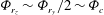
In figures 7 and 8 the behaviour of two generic field lines of scale-energy flux is addressed showing in (a) the scales,
 $r_{z}$
,
$r_{z}$
,
 $r_{y}$
,
$r_{y}$
,
 $|\boldsymbol{r}|$
and the wall-normal position
$|\boldsymbol{r}|$
and the wall-normal position
 $Y_{c}$
while in (b) the strengths of flux
$Y_{c}$
while in (b) the strengths of flux
 $|{\it\Phi}|$
and source
$|{\it\Phi}|$
and source
 ${\it\xi}$
as a function of the arc length
${\it\xi}$
as a function of the arc length
 $$\begin{eqnarray}{\it\gamma}=\int \,\text{d}{\it\gamma}\quad \text{with }\text{d}{\it\gamma}=\sqrt{(\text{d}r_{z}^{2}+\text{d}r_{y}^{2}+\text{d}Y_{c}^{2})}.\end{eqnarray}$$
These field lines are selected as representative of the structure of the scale-energy paths schematized in figure 6(a,b), and are shown respectively in figures 7 and 8. The paths start from the transition between regions 1 and 2. Different trends are consistently observed in the different regions, however the parametrization in terms of arc length might be specific to the particular stream line.
The first part of the field line of figure 7(a), see the sketch in figure 6(b), after a short transition, involves scales increasing linearly with wall distance,
 $r_{z}^{+}\sim {\rm\Delta}z_{d}^{+}+Y_{c}^{+}$
(dashed grey line) and
$r_{z}^{+}\sim {\rm\Delta}z_{d}^{+}+Y_{c}^{+}$
(dashed grey line) and
 $r_{y}^{+}\sim 2Y_{c}^{+}-30$
(dashed black line). This is region 2 of figure 6 where
$r_{y}^{+}\sim 2Y_{c}^{+}-30$
(dashed black line). This is region 2 of figure 6 where
 ${\it\Phi}_{r_{z}}\sim {\it\Phi}_{r_{y}}/2\sim {\it\Phi}_{c}$
and a reverse cascade spatially moving away from the wall in the plane of attached scales takes place. Successively, in region 3b, the flux, while remaining in the attached plane
${\it\Phi}_{r_{z}}\sim {\it\Phi}_{r_{y}}/2\sim {\it\Phi}_{c}$
and a reverse cascade spatially moving away from the wall in the plane of attached scales takes place. Successively, in region 3b, the flux, while remaining in the attached plane
 $r_{y}^{+}\sim 2Y_{c}^{+}-30$
(dashed black line), bends towards smaller spanwise scales (dashed grey line), as appreciated by the change of the sign of
$r_{y}^{+}\sim 2Y_{c}^{+}-30$
(dashed black line), bends towards smaller spanwise scales (dashed grey line), as appreciated by the change of the sign of
 ${\it\Phi}_{r_{z}}$
. Finally, both the spanwise and wall-normal scales (dashed grey and black line respectively) decrease forming an ascending detached forward cascade up to dissipation, region 4 of figure 6(b). In figure 8(a) the picture is the same with the exception that, instead of region 3b, a reverse cascade at detached scale,
${\it\Phi}_{r_{z}}$
. Finally, both the spanwise and wall-normal scales (dashed grey and black line respectively) decrease forming an ascending detached forward cascade up to dissipation, region 4 of figure 6(b). In figure 8(a) the picture is the same with the exception that, instead of region 3b, a reverse cascade at detached scale,
 $r_{y}^{+}<2Y_{c}^{+}-30$
, takes place, namely region 3a of figure 6(a).
$r_{y}^{+}<2Y_{c}^{+}-30$
, takes place, namely region 3a of figure 6(a).

Figure 7. (a) Turbulent scales intercepted among their path
 ${\it\gamma}$
by one selected streamtrace of scale-energy flux corresponding to the picture described in figure 6(b):
${\it\gamma}$
by one selected streamtrace of scale-energy flux corresponding to the picture described in figure 6(b):
 $|\boldsymbol{r}|({\it\gamma})$
solid line,
$|\boldsymbol{r}|({\it\gamma})$
solid line,
 $r_{z}({\it\gamma})$
dashed grey line,
$r_{z}({\it\gamma})$
dashed grey line,
 $r_{y}({\it\gamma})$
dashed black line and
$r_{y}({\it\gamma})$
dashed black line and
 $Y_{c}({\it\gamma})$
squares. (b) Behaviour of the intensity of the flux,
$Y_{c}({\it\gamma})$
squares. (b) Behaviour of the intensity of the flux,
 $|\unicode[STIX]{x1D731}|$
(black line) and of the source
$|\unicode[STIX]{x1D731}|$
(black line) and of the source
 ${\it\xi}$
(grey line) as a function of the path
${\it\xi}$
(grey line) as a function of the path
 ${\it\gamma}$
. The dashed line is the power law
${\it\gamma}$
. The dashed line is the power law
 $|\unicode[STIX]{x1D731}|=3{\it\gamma}^{-1/4}$
and the dashed dotted line is
$|\unicode[STIX]{x1D731}|=3{\it\gamma}^{-1/4}$
and the dashed dotted line is
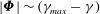 $|\unicode[STIX]{x1D731}|\sim ({\it\gamma}_{max}-{\it\gamma})$
.
$|\unicode[STIX]{x1D731}|\sim ({\it\gamma}_{max}-{\it\gamma})$
.

After discussing the geometry of the flux field lines, let us address the strength of the flux and of the source (figure 7 b). Following the transition region, where the intensity of the reverse cascade increases due to the action of the source term (grey line), in region 2 the flux strength decreases along the reverse cascade which takes place in the plane of attached scales (black line). Our data show that the intensity of the flux follows a power law,
 $$\begin{eqnarray}|\unicode[STIX]{x1D731}|\sim {\it\gamma}^{-1/4},\end{eqnarray}$$
suggesting a self-similar process linked to the cascade. In the meanwhile the source is very active implying that the reverse cascade gains scale energy from the nearly constant source,
 ${\it\xi}\sim \text{const.}>0$
, at attached scales (grey line). As shown in figure 7(b), by entering region 3b, still in the plane of attached scales, the field lines bend towards smaller
${\it\xi}\sim \text{const.}>0$
, at attached scales (grey line). As shown in figure 7(b), by entering region 3b, still in the plane of attached scales, the field lines bend towards smaller
 $r_{z}$
(
$r_{z}$
(
 ${\it\Phi}_{r_{z}}<0$
) and the intensity of the flux (black line) drastically increases. At the same time the source (grey line) decreases to eventually become negative at the end of this region. Contextually the flux tubes are squeezed. Finally, the flux detaches from the plane, region 4, and intercepts smaller spanwise and wall-normal scales while ascending to larger wall distances. As shown in figure 7(b), in this region, the source term (grey line) is consistently negative,
${\it\Phi}_{r_{z}}<0$
) and the intensity of the flux (black line) drastically increases. At the same time the source (grey line) decreases to eventually become negative at the end of this region. Contextually the flux tubes are squeezed. Finally, the flux detaches from the plane, region 4, and intercepts smaller spanwise and wall-normal scales while ascending to larger wall distances. As shown in figure 7(b), in this region, the source term (grey line) is consistently negative,
 ${\it\xi}<0$
, with turbulence sustained only by the decreasing flux (black line). The intensity of the flux behaves linearly with the arc length along the field line,
${\it\xi}<0$
, with turbulence sustained only by the decreasing flux (black line). The intensity of the flux behaves linearly with the arc length along the field line,
 $$\begin{eqnarray}|\unicode[STIX]{x1D731}|\sim {\it\gamma}_{max}-{\it\gamma},\end{eqnarray}$$
see the dash-dotted line in the logarithmic plot of figure 7(b). In the corresponding range of figure 7(a) the scale
 $|\boldsymbol{r}|$
is shown to decrease linearly with
$|\boldsymbol{r}|$
is shown to decrease linearly with
 ${\it\gamma}$
, implying that the flux strength decreases linearly with the scale. This is consistent with Kolmogorov description of inertial range of turbulence (direct cascade) that should occur at intermediate scales in the overlap layer. This process is eventually terminated by the dissipation occurring at small scales.
${\it\gamma}$
, implying that the flux strength decreases linearly with the scale. This is consistent with Kolmogorov description of inertial range of turbulence (direct cascade) that should occur at intermediate scales in the overlap layer. This process is eventually terminated by the dissipation occurring at small scales.
In figure 8(b), the picture is qualitatively the same except for the third region, region 3a of figure 6(a), where the flux detaches from the plane of attached scales flowing toward larger spanwise and wall-normal scales while increasing the distance from the wall to form a detached reverse cascade. In contrast to region 3b, the intensity of the flux (black line) reaches a minimum while detaching. After bending toward small spanwise scales while still moving toward larger wall-normal scales the flux starts to increase. The maximum flux intensity is finally observed where the forward cascade begins and both
 $r_{y}$
and
$r_{y}$
and
 $r_{z}$
decrease, region 4.
$r_{z}$
decrease, region 4.
Summarizing, in region 1 and in the transitional layer of the scale-energy path, the strong scale-energy source in the inner layer plays a leading role defining the singularity point for the fluxes and sustaining the hierarchy of spanwise scales emerging from the buffer layer. The scale-energy source in this region represents also the triggering mechanisms for the reverse cascades toward the attached scales of motion at larger distances from the wall in the overlap layer. In these attached scales the source term is very large thus sustaining the reverse cascade toward larger attached scales located further away from the wall and the continuous detachment of fluxes toward smaller detached scales up to dissipation (forward cascade). This last consideration could corroborate the idea of an overlap layer independent from the near-wall region and where the attached scales sustain, rather than being fed by, the spatial reverse cascade triggered in the buffer layer.
In closing this section let us propose a possible description of the detachment of the scale-energy path from the plane of attached scales. By considering a coordinate system
 $({\it\tau}_{1},{\it\tau}_{2},{\it\eta})$
with
$({\it\tau}_{1},{\it\tau}_{2},{\it\eta})$
with
 ${\bf\tau}=({\it\tau}_{1},{\it\tau}_{2})$
and
${\bf\tau}=({\it\tau}_{1},{\it\tau}_{2})$
and
 ${\it\eta}$
aligned and normal to the plane of attached scales, respectively, we can rewrite (2.2) as
${\it\eta}$
aligned and normal to the plane of attached scales, respectively, we can rewrite (2.2) as
 $$\begin{eqnarray}\boldsymbol{{\rm\nabla}}_{{\it\tau}}\boldsymbol{\cdot }\unicode[STIX]{x1D731}_{{\it\tau}}({\bf\tau},{\it\eta})+\frac{\partial {\it\Phi}_{{\it\eta}}}{\partial {\it\eta}}({\bf\tau},{\it\eta})={\it\zeta}({\bf\tau},{\it\eta}),\end{eqnarray}$$
with
 ${\it\zeta}={\it\xi}-\partial {\it\Phi}_{x}/\partial r_{x}$
to be understood as an extended source term. By the inspection of the data, we found that the topology of
${\it\zeta}={\it\xi}-\partial {\it\Phi}_{x}/\partial r_{x}$
to be understood as an extended source term. By the inspection of the data, we found that the topology of
 ${\it\zeta}$
is essentially the same of
${\it\zeta}$
is essentially the same of
 ${\it\xi}$
. As shown in § 3, in the overlap layer, the strong positive values of the source term are concentrated in a very thin layer aligned to the plane of attached scales. The extended source
${\it\xi}$
. As shown in § 3, in the overlap layer, the strong positive values of the source term are concentrated in a very thin layer aligned to the plane of attached scales. The extended source
 ${\it\zeta}$
appears to be weakly dependent on
${\it\zeta}$
appears to be weakly dependent on
 ${\bf\tau}$
while in the
${\bf\tau}$
while in the
 ${\it\eta}$
direction it can be roughly modelled as a Dirac delta function,
${\it\eta}$
direction it can be roughly modelled as a Dirac delta function,
 $$\begin{eqnarray}{\it\zeta}\simeq {\it\zeta}({\it\eta})\propto {\it\delta}({\it\eta}).\end{eqnarray}$$
Hence, (5.4) can be rewritten as
 $$\begin{eqnarray}\boldsymbol{{\rm\nabla}}_{{\it\tau}}\boldsymbol{\cdot }\unicode[STIX]{x1D731}_{{\it\tau}}({\it\eta})+\frac{\partial {\it\Phi}_{{\it\eta}}}{\partial {\it\eta}}({\it\eta})\propto {\it\delta}({\it\eta}).\end{eqnarray}$$
In accordance with the scale-energy paths, we argue that the strong concentration of the scale-energy source mostly reflects on the normal divergence of the fluxes, hence
 $$\begin{eqnarray}\frac{\partial {\it\Phi}_{{\it\eta}}}{\partial {\it\eta}}\propto {\it\delta}({\it\eta}),\end{eqnarray}$$
thus leading to a normal component proportional to a Heaviside step function
 $$\begin{eqnarray}{\it\Phi}_{{\it\eta}}\propto H({\it\eta}).\end{eqnarray}$$
This jump of the normal component of the flux describes the detachment of the scale-energy paths and could be related to the increase of the intensity of the flux observed in regions 3a and 3b and shown in figures 7 and 8, respectively.
6 Final remarks
The elusive nature of wall-bounded turbulence is related to the multidimensionality of energy transfer, production and dissipation which combines phenomena occurring in the space of scales with those taking place in physical space. Different form of energy cascade, both toward small and large scale, and the related spatial fluxes toward the bulk flow are intermingled and cannot be analysed separately.
A suitable instrument to study this energy transfer in the multidimensional space of scales and position is the generalized Kolmogorov equation for the second-order structure function which addresses the velocity difference between two points in space. The equation could be considered the natural tool for the statistical analysis of general turbulent flows that lack a classical spectral decomposition due to violation of spatial homogeneity. This approach allows the cascade mechanisms by which energy is transported among different flow regions and different scales to be addressed.
The equation has already been studied in Cimarelli et al. (Reference Cimarelli, De Angelis and Casciola2013) and Cimarelli et al. (Reference Cimarelli, De Angelis, Schlatter, Brethouwer, Talamelli and Casciola2015) in the reduced space of spanwise and streamwise scales and wall-normal distances. In addition complementing the available information, the purpose here was mainly to distinguish the transport processes in wall-normal scales from those taking place in the physical wall-normal direction, a distinction that could not be addressed in the previous conditions, given the constraint
 $r_{y}=0$
which here we relaxed. Apart from that, the two reduced views for
$r_{y}=0$
which here we relaxed. Apart from that, the two reduced views for
 $r_{y}=0$
and
$r_{y}=0$
and
 $r_{x}=0$
should be considered as entirely complementary and part of a general description in the four-dimensional space of positions and scales provided by the generalized Kolmogorov equation.
$r_{x}=0$
should be considered as entirely complementary and part of a general description in the four-dimensional space of positions and scales provided by the generalized Kolmogorov equation.
Three driving mechanisms are found for the energy flux, two of which were already identified in the previous works. The previous two correspond to a strong source in the buffer layer related to the near-wall cycle of turbulence and to an outer one here better characterized as belonging to the region of detached scales. The newly identified source lives at attached scales in the overlap layer. These sourcing mechanisms lead to a complex redistribution of energy where spatially evolving forward and reverse cascades coexist involving respectively detached and attached scales of motion. The picture is as follows. A hierarchy of spanwise scales is generated in the buffer layer through local sourcing mechanisms. Successively, through a reverse cascade, energy flows toward large spanwise scales at constant distance from the wall. The strong source associated with this hierarchy of spanwise scales triggers a reverse cascade in the overlap layer that climbs the inclined plane of attached scales toward increasing separations and further away from the wall. The switch between the two attached/detached dominated regions of the flow is given by
 $Y_{c}^{+}=20$
. The newly identified source in the attached scales strongly contributes to sustain the reverse cascade toward larger attached scales further away from the wall and to initialize the forward cascade toward small dissipative scales which also ascends toward the channel centre. All of these features could be consistent with the notion of an overlap layer independent of the near-wall energy source region.
$Y_{c}^{+}=20$
. The newly identified source in the attached scales strongly contributes to sustain the reverse cascade toward larger attached scales further away from the wall and to initialize the forward cascade toward small dissipative scales which also ascends toward the channel centre. All of these features could be consistent with the notion of an overlap layer independent of the near-wall energy source region.
In the region of the attached scales the flux, going from small to large scales and toward the bulk of the flow, follows a power law,
 $|\unicode[STIX]{x1D731}|\sim {\it\gamma}^{-1/4}$
, consistently with the idea of a self-similar process for the reverse cascade. In the region of detached scales the flux reverts to small scales still going toward the bulk. This is the process which brings scale energy to the eventual dissipation thus closing the turbulent cycle from production to dissipation. Nevertheless, detached scales are not entirely characterized by a direct cascade toward small scales. Actually a detached reverse cascade is found at large spanwise separations,
$|\unicode[STIX]{x1D731}|\sim {\it\gamma}^{-1/4}$
, consistently with the idea of a self-similar process for the reverse cascade. In the region of detached scales the flux reverts to small scales still going toward the bulk. This is the process which brings scale energy to the eventual dissipation thus closing the turbulent cycle from production to dissipation. Nevertheless, detached scales are not entirely characterized by a direct cascade toward small scales. Actually a detached reverse cascade is found at large spanwise separations,
 $r_{z}>\tilde{r}_{z}$
, and is presumably related to the presence of the outer source at detached scales that was already identified in a previous paper. Generally speaking, spatial redistribution of energy, moving away from the wall, is always present in the channel flow. As already commented on, this makes necessary to distinguish between the wall-normal spatial component of the flux and the one occurring in wall-normal separation. The resulting picture consists of energy produced at a certain distance from the wall and dissipated further away from it. The reverse cascade which energizes the larger scales is followed by a forward cascade combined with a spatial component of the flux toward the bulk. A putative inertial range is expected for intermediate small detached scales within the overlap layer. Following the flux in this range, the topmost one of the two points among which the velocity difference is evaluated remains at a constant distance from the wall.
$r_{z}>\tilde{r}_{z}$
, and is presumably related to the presence of the outer source at detached scales that was already identified in a previous paper. Generally speaking, spatial redistribution of energy, moving away from the wall, is always present in the channel flow. As already commented on, this makes necessary to distinguish between the wall-normal spatial component of the flux and the one occurring in wall-normal separation. The resulting picture consists of energy produced at a certain distance from the wall and dissipated further away from it. The reverse cascade which energizes the larger scales is followed by a forward cascade combined with a spatial component of the flux toward the bulk. A putative inertial range is expected for intermediate small detached scales within the overlap layer. Following the flux in this range, the topmost one of the two points among which the velocity difference is evaluated remains at a constant distance from the wall.
As a final comment, we stress that the terminology we have adopted throughout the paper should be considered as suggestive of the physical meaning of the statistical objects we were considering. In particular, as recommended in § 2, the terms scale energy and scale-energy flux should not be take too literally. Actually, energy is by definition an additive quantity. The scale energy is not. Its name is only intended to convey the idea that the scale energy or, more technically, the second-order structure function, obeys a conservation equation where the divergence of the relevant flux is determined by suitable sources. At small scales, the scale energy could be approximately accepted as a measure of the intensity of the eddies living at those scales. At larger scales this interpretation is misleading. Anyhow, the flux that is eventually dissipated by viscosity at small scales can be rightfully referred to as the flux of scale energy. If we trace back this flux we identify the corresponding sources and in doing so we felt entitled to keep calling it the scale-energy flux. By extension, the transported quantity, the second-order structure function, was nicknamed scale energy. To conclude, we reinforce that the paths the scale energy takes in the combined space of scale and positions is a clear indication of the processes occurring in the system. Clearly, the overall picture is rather complex even in the relatively simple context of a canonical channel flow.
Acknowledgements
The authors would like to acknowledge the support of the European Research Council, which funded the Multiflow summer program within which this work was conceived and partially developed. We acknowledge the technical support of Dr J. Hackl, who helped us to manage the computing resources of the School of Aeronautics, Universidad Politécnica de Madrid, which is also acknowledged.


 Open access